

Page 1
ParaDyme Radio Option Kits
ParaDyme (PN 200-0473-02)
ParaDyme (PN 200-0473-03)
Hardware Installation Guide
PN: 602-0249-04-A
Page 2

LEGAL DISCLAIMER
The manufacturer disclaims any liability for damage or injury that results from failure to follow the instructions and warnings
set forth herein.
Note: The installation procedures must be performed by an authorized, fully trained and certified dealer technician.
Note: Read and follow ALL instructions in this guide carefully before installing any hardware or operating the steering
system.
Note: Take careful note of the information in the Safety Information section and throughout this guide.
ii Radio Option Kits
Page 3

Special Requirements
Tools
This list consists of special tools required to complete the installation. A complete set of common installation tools is assumed.
ESDS Anti-electrostatic wrist strap 5/8" open wrench 12mm open wrench
2" x 4"x 10" wood spacer blocks (or
other spacer)
8mm Open End Torque Wrench
((set to 8in-lbs (0.9 Newton meters))
Torque driver with #0 Phillips bit
((set to 2in-lbs (0.2 Newton meters))
Torque driver with #1 Phillips bit
((set to 5in-lbs (0.6 Newton meters))
Torque driver with #2 Phillips bit
((set to 20in-lbs (2.3 Newton meters))
a. In order to prevent possible damage during assembly use the correct torque specification and tools. An adjustable
torque driver can be used in place of multiple preset torque drivers. Failure to use the correct tools and
procedures may void the manufacturer's warranty.
a
a
a
#0 Phillips screwdriver 24mm open wrench
#1 Phillips screwdriver 8mm Allen wrench
a
#2 Phillips screwdriver Ten Foot Ladder
Wire cutters Cleaning rags and cleaning brush
Flat screwdriver
Technical Support
Refer to your owner's manual for technical support information.
Contact Information
Refer to your owner's manual for contact information.
Copyright © 2011 All Rights Reserved.
Hardware Installation Guide iii
Page 4

iv Radio Option Kits
Page 5

Table of Contents
Chapter 1 Introduction ................................................................................................... 1
Chapter 2 Safety and Regulatory Requirements ................................................................. 3
FCC Requirements. . . . . . . . . . . . . . . . . . . . . . . . . . . . . . . . . . . . . . . . . . . . . . . . . . . . . . . . . . . 3
Regulatory Information . . . . . . . . . . . . . . . . . . . . . . . . . . . . . . . . . . . . . . . . . . . . . . . . . . . . . . . 4
RF Exposure Information. . . . . . . . . . . . . . . . . . . . . . . . . . . . . . . . . . . . . . . . . . . . . . . . . . . . . . 5
ESDS Precautions . . . . . . . . . . . . . . . . . . . . . . . . . . . . . . . . . . . . . . . . . . . . . . . . . . . . . . . . . . . 5
Handling Requirements. . . . . . . . . . . . . . . . . . . . . . . . . . . . . . . . . . . . . . . . . . . . . . . . . . . . . 5
Important Regulatory Information . . . . . . . . . . . . . . . . . . . . . . . . . . . . . . . . . . . . . . . . . . . . . . 6
Nota Importante. . . . . . . . . . . . . . . . . . . . . . . . . . . . . . . . . . . . . . . . . . . . . . . . . . . . . . . . . . . 6
Restricciones de uso . . . . . . . . . . . . . . . . . . . . . . . . . . . . . . . . . . . . . . . . . . . . . . . . . . . . . . . 6
WICHTIGER HINWEIS. . . . . . . . . . . . . . . . . . . . . . . . . . . . . . . . . . . . . . . . . . . . . . . . . . . . 7
BETRIEBSERLAUBNIS . . . . . . . . . . . . . . . . . . . . . . . . . . . . . . . . . . . . . . . . . . . . . . . . . . . 7
Chapter 3 Radio Modem Kits Installation Overview ............................................................ 9
Pre-Installation Verification. . . . . . . . . . . . . . . . . . . . . . . . . . . . . . . . . . . . . . . . . . . . . . . . . . . . 9
Kit Overviews . . . . . . . . . . . . . . . . . . . . . . . . . . . . . . . . . . . . . . . . . . . . . . . . . . . . . . . . . . . . . 10
OmniSTAR Receiver Kit. . . . . . . . . . . . . . . . . . . . . . . . . . . . . . . . . . . . . . . . . . . . . . . . . . . 10
900 MHz Radio Modem Kit . . . . . . . . . . . . . . . . . . . . . . . . . . . . . . . . . . . . . . . . . . . . . . . . 11
UHF Radio Modem Kits . . . . . . . . . . . . . . . . . . . . . . . . . . . . . . . . . . . . . . . . . . . . . . . . . . . 12
VHF Radio Modem Kits . . . . . . . . . . . . . . . . . . . . . . . . . . . . . . . . . . . . . . . . . . . . . . . . . . . 13
Chapter 4 Radio Modem Kits Installation......................................................................... 15
Preparation. . . . . . . . . . . . . . . . . . . . . . . . . . . . . . . . . . . . . . . . . . . . . . . . . . . . . . . . . . . . . . . . 15
Changing or Installing a SIM Card . . . . . . . . . . . . . . . . . . . . . . . . . . . . . . . . . . . . . . . . . . . . . 18
OmniSTAR Receiver Kit Installation Procedure (200-0504-02 Kit) . . . . . . . . . . . . . . . . . . . 21
900 MHz RTK Radio Modem Kit Installation Procedure (200-0505-04 Kit) . . . . . . . . . . . . 24
UHF and VHF Radio Modem Kit Installation Procedure . . . . . . . . . . . . . . . . . . . . . . . . . . . . 32
ParaDyme Smart Antenna Bottom Cover Installation Procedure . . . . . . . . . . . . . . . . . . . . . . 41
Antenna Installation Procedure . . . . . . . . . . . . . . . . . . . . . . . . . . . . . . . . . . . . . . . . . . . . . . . . 44
Hardware Installation Guide v
Page 6

vi Radio Option Kits
Page 7

1
Introduction
The ParaDyme system is a user-friendly GPS and steering control solution for agricultural vehicles. Combined with one of the
many compatible displays, it is at the heart of a full-featured precision agriculture product. The ParaDyme system is capable of
providing year round precision machine control that is easy-to-use and transferable to multiple vehicles. This flexibility makes
ParaDyme a vital tool for a complete integrated farm management syst em.
The ParaDyme system offers a number of ways to interface with a variety of correction sources. This allows the user to choose
the correction source and accuracy they require for their particular needs. The ParaDyme supports WAAS/EGNOS,
OmniSTAR, and RTK via radio or cell modem corrections with optional internal 161MHZ, 450MHz, and 900 MHz radio
modem kits. Once the hardware has been installed, the ParaDyme can be easily switched from one correction source to another
as needed via the Display.
For details about the capabilities and operation of the optional radio modem and OmniSTAR receiver kit features, refer to your
ParaDyme Owner's Manual.
The ParaDyme system requires specific hardware for each correction source. This manual provides the instructions for
installing the various hardware components in the field, so that they can be added after the ParaDyme has shipped from the
factory.
ParaDyme systems shipped without RTK or OmniST AR support (part number 200-0473-02 or earlier) were shipped from the
factory with three antennas and all the coax cables required to install RTK or OmniSTAR in the field. ParaDyme systems with
part number 200-0473-03 no longer come with all of these cables pre-installed. The coax cables and antennas are now supplied
only with the Radio Install Kits. Also, ParaDyme systems with part number 200-0473-03 or later no longer come with a WiFi
antenna or connector.
This installation manual covers the installation of these radio kits with the expectation that the ParaDyme system being
upgraded is a 200-0473-03 or later model. If it is one of the earlier models, some of the instructions in this manual may differ,
and some parts may be left over after the installation. These differences will be noted in the document as necessary.
Hardware Installation Guide 1
Page 8

Introduction
2 Radio Option Kits
Page 9
2
Safety and Regulatory Requirements
The ParaDyme system installer and manufacturer disclaim any responsibility for damage or physical harm caused by failure to
adhere to the following requirements:
• The ParaDyme system must be operated by a trained and qualified operator.
• The operator must never leave the vehicle while the ParaDyme system is engaged.
• The ParaDyme system is not designed to replace the vehicle operator.
WARNING
To avoid electrical shock hazards, remove the Roof Module
from the vehicle before driving under low structures or low
electrical power lines.
FCC Requirements
A license from the FCC is required for owners of 4XX MHz radios which transmit radio signals while operating in the United
States. This would include any Base Station transmitting within this frequency range. The owner of the Base Station is
required to have this license; however the owner of the rover (vehicle) system does not require a license to operate 4XX MHz
radio. The rover radio only receives the signal and does not transmit anything.
This device is intended for use in the operation of commercial activities, educational, philanthropic, or ecclesiastical
institutions, and hospitals, clinics, or medical associations.
If a 4XX MHz radio is used to transmit a signal, the Federal Communications Commission (FCC) requires that you to have a
license before you operate this device. Unless you are already licensed to operate on one of the preset frequencies, you must
apply for a frequency through the PCIA (Personal Communication Industry Association), a non-profit organization that
assigns frequencies nationwide to help prevent conflicts between different businesses using devices in the same area. For more
information about getting a license, contact the PCIA at 800-759-0300, extension 3068 (in Virginia 703-739-0300, extension
3068).
For other questions concerning the license application, contact the FCC at 717-337-1212, or write:
FCC
P.O. Box 1040
Gettysburg, PA 17325
For the latest FCC application form and instructions, call the FCC's fax-on demand service at 1-202-418-0177 from a fax
machine and request one or more of the following documents:
All forms and instructions 000600
If you do not have a fax machine, you can call the Government Forms Distribution Center at 1-800-418-FORM and request
that the form and instructions be mailed to you.
Hardware Installation Guide 3
Page 10

Regulatory Information
Regulatory Information
The Novariant 802.11 b/g radio module is installed in close proximity to other radio modules. This device complies with Part
15 of the FCC Rules. This device shall be professionally installed and maintained by a trained technician as directed by FCC
regulations. Use of an antenna other than that outlined in the FCC and IC certification filings for each of the radio products
may violate FCC regulations. This device operation is subject to the following two conditions:
1. It may not cause harmful interference.
2. It must accept any interference received, including interference that may cause undesired operation. It is your
responsibility to certify that your radio transmitter is operating legally on an authori zed frequency in your country and
locality. Contact your local government telecommunications authority to obtain information on licensing requirements and
request an operating license. Failure to operate on an authorized frequency will cause harmful radio interference to other
radio users and possible disruptions of important radio services. Failure to operate a radio transmitting device such as a
base station with the appropriate license may result in prosecution and severe penalties.
Table 2-1 Regulatory Information for Various ParaDyme Radio Configurations
Manufacturer Description
Novariant 802.11 b/g Radio TMN-WMIA-166AGI
Multi-Tech
1
CDMA MMC Modem AU792A04A22750
FCC ID
(CANADA IC)
(8490A-WMIA166AGI)
(125A-0010)
Novariant
Freewave
2
2
Intelligent Wireless
900 MHz FHSS Radio
900MHz Radio, MM2, Modem
1
Products Inc CDMA Single Channel RF Amplifier RFK-LMSWDJH819
KNY-6231812519
(2329B-DGR09RAS)
KNY-42182112519
(2329B-FGR2)
(5252A-CA819)
1
Telit
Quad Band GSM Modem R17UC864G
(5131A-UC864G)
[CE 0984]
1
Telit
CDMA, CC864-DUAL, Aeris Modem RI7CC864-DUAL
(6131A-CC864-DUAL)
SATEL Modem Receiver 403-470 MHz MRB-SATELTA10
(2422A-SATELTA10)
[CE 0523]
SATEL Modem Receiver 150-174 MHz [CE 0523]
1
The Multi-Tech MMC Modem or Telit CC854-DUAL Modem drives the Intelligent Wireless Products amplifier and is used
only in CDMA mode.
2
Whenever any Novariant Radio Module is mounted inside an enclosure, the enclosure must have a visual label on the
outside featuring the module FCC ID.
4 Radio Option Kits
Page 11
RF Exposure Information
Note: Radio modems users in North America should be aware that due to the allocation of the frequency band 406.0 -
406.1 MHz to be used for government use only, the use of radio modem on this frequency band without a proper permit
is strictly forbidden.
RF Exposure Information
CAUTION
FCC RF Exposure Requir ements
The antennas connected to the radios listed in Table 2-1 on
page 4 must be mounted at least 26.6 cm away from nearby
persons to comply to FCC RF exposure requirements.
Configurations using radio modules not described above or which use antennas not qualified for the radio modules above
require further equipment authorization.
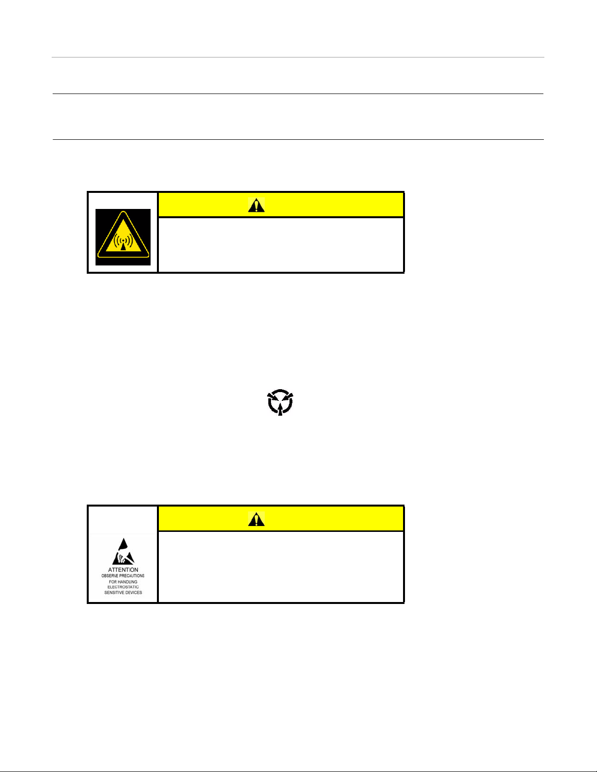
ESDS Precautions
An Electrostatic Discharge Sensitive (ESDS) device is an electronic component which can be damaged by an electrostatic
charge or discharge through its assemblies and conductors.
ESDS devices are identified by the following symbol:
Handling Requirements
Observe special handling procedures required for ESDS devices. Failure to follow these procedures can result in equipment
damage. Use an anti-electrostatic wrist strap when handling ESDS devices.
CAUTION
ESDS Device Requirements
This equipment contains parts and assemblies sensitive to
damage by electrostatic discharge (ESD). Use ESDS
precautionary procedures when touching, removing, or
installing assemblies.
Hardware Installation Guide 5
Page 12

Important Regulatory Information
Important Regulatory Information
Nota Importante
Todos los derechos sobre este manual son propiedad exclusiva de Novariant OY (Novariant de ahora en adelante). Todos los
derechos están reservados. La reproducción de este manual sin la autorización por escrito del propietario de los derechos, ya
sea por impresión, fotocopia, grabación o por cualquier otro medio, o la traducción total o parcial del manual a cualquier
idioma incluyendo todos los lenguajes de programación que usan cualquier manual eléctrico, mecánico, magnético, óptico, u
otros métodos está prohibida.
Novariant se reserva el derecho de cambiar las especificaciones técnicas o funciones de sus productos, de cesar en la
producción o soporte de cualquiera de sus productos sin previo aviso por escrito e insta a sus clientes a asegurar, que la
información a su disposición es válida.
El software y programas de Novariant se entregan tal cual. El fabricante no ofrece ningún tipo de garantía de venta o
relacionadas con la aplicabilidad de una cierta aplicación. El fabricante o empresa técnica de d esarrollo de un programa, no se
responsabiliza en ningún caso, de posibles daños causados por el uso del programa. Los nombres de los programas así como
sus copyrights son de única propiedad de Novariant. Cualquier cesión, concesión a una tercera parte, leasing, renting,
transporte, copia, edición, traducción, cambio a cualquier otro lenguaje de programación o ingeniería inversa está prohibida
sin el consentimiento escrito de Novariant.
LOS PRODUCTOS DE NOVARIANT NO HAN SIDO DISEÑADOS, INVENTADOS NI INSPECCIONADOS PARA
USARSE EN MEDIOS RELACIONADOS CON EL SOPORTE VITAL O FUNCIONES RELACIONADAS AL SISTEMA,
NI COMO PARTE DE CUALQUIER OTRO SISTEMA CRÍTICO Y NO OFRECEN GARANTÍA DE
FUNCIONAMIENTO SI SON USADOS EN CUALQUIER DE LAS APLICACIONES MENCIONADA S.
Salo, FINLANDIA 2000 Los radio módems SATELLINE-3AS (d) han sido diseñados para operar en rangos de frecuencia, su
uso exacto difiere de una región / país a otra/o. El usuario de un radio módem debe tener cuidado de que dicho aparato no
opere sin el permiso de las autoridades locales en salvo en esas frecuencias reservadas específicamente para uso sin permiso
específico. Por esta razón, la marca se encuentra unida al radio módem.
Restricciones de uso
El modelo SATELLINE-3AS (d) 869 MHz está diseñado para operar en la banda de frecuencia 869.400-869.650MHz sin
necesidad de permiso, según las normas CEPT/ERC/REC 70-03. Esta recomendación ha sido emitida por el Comité Europeo
de Radiocomunicaciones (ERC) bajo el CEPT. El ciclo de transmisión /recepción de la unidad individual está limitada a 10%
en esta banda, y el período singular de transmisión no debe exceder los 36s. Además, la potencia máxima irradiada permitida
es de 500 mWerb.
AVISO! Los usuarios de SATELLINE-3AS(d) en Norte-América deben saber que debido a la localización de la banda de
frecuencia 406.0-406.1 MHz para uso exclusivo del Gobierno, el uso del radio módem en esta banda de frecuencia sin
permiso, está estrictamente prohibido.
NOTA PARA ESPAÑA SEGÚN RD 1890/2000
CE0341
Este equipo requiere licencia administrativa. Dirección en España:
RADIOCOM MULTICOMUNICACIONES, S.A. C/ISABEL COLBRAND 10. ED. ALFA III-NAVE 93 28050 MADRID
6 Radio Option Kits
Page 13

WICHTIGER HINWEIS
GARANTIA E INSTRUCCIONES DE SEGURIDAD
Lea estas instrucciones de seguridad cuidadosamente antes de usar el producto:
• La garantía será nula, si el producto se utiliza en cualquiera de las formas que son contrarias a las instrucciones dadas en
este manual, o si la caja del radio módem ha sido abierta o manipulada.
• El radio módem debe utilizarse solo en frecuencias asignadas por las autoridades locales y sin exceder la potencia máxima
permitida. Novariant no es responsable, si los productos fabricados son usados de forma ilegal.
• Los aparatos mencionados en este manual deben utilizarse según las instrucciones descritas en este manual. Se garantiza las
operaciones impecables y de seguridad de los aparatos solo si el transporte, almacenaje, operación y manipulación de los
aparatos es correcto. Esto también es aplicable al mantenimiento de los productos.
• Para prevenir el daño tanto del radio módem como de cualquier terminal debe siempre estar apagado (OFF) antes de
conectar o desconectar el cable de conexión de serie. El usuario debería asegurarse de que los diferentes aparatos utilizados
tengan el mismo potencial de tierra. Antes de conectar cualquier cable de potencia el voltaje del suministro debe ser
comprobado.
WICHTIGER HINWEIS
Alle Rechte an diesem Handbuch gehören allein Novariant OY (in diesem Handbuch als Novariant bezeichnet). All Rechte
sind vorbehalten. Vervielfältigung dieses Handbuches (ohne die schriftliche Zustimmung des Eigentümers) durch Druck,
Kopie, Aufzeichnung oder andere Methoden, oder die volle oder teilweise Übersetzung des Handbuches in eine andere
Sprache einschließlich Programmiersprachen, mittels elektrischer, mechanischer, magnetischer, optischer, manueller oder
anderer Methoden oder Geräte ist verboten.
Novariant behält sich das Recht vor, technische Spezifikationen oder Funktionen der eigenen Produkte zu ändern, die
Herstellung dieser Produkte oder den Support für eines dieser Produkte einzustellen, ohne dass es einer schriftlichen
Ankündigung oder Mitteilung der Kunden bedarf. Der Kunde hat sicherzustellen, dass die ihm zur Verfügung stehenden
Informationen gültig sind.
Novariant Software und Programme werden geliefert, wie sie sind (”as is”). Der Hersteller übernimmt keinerlei
Gewährleistung und Garantie für die Funktionalität und Anwendbarkeit einer bestimmten Applikation. Der Hersteller oder
Entwickler eines Programms übernimmt in keinem Fall die V era ntwortung für irgendwelche Schäden, die durch den Gebrauch
des Programms entstanden sind. Die Namen der Programme und die copyrights für diese entsprechenden Programme sind das
alleinige Eigentum von Novariant. Jede Übertragung, Lizensierung für einen Dritten, Leasing, Vermietung, Versendung, sowie
das Kopieren, Bearbeiten, Übersetzen, Verändern in eine andere Programmiersprache oder “Reverse Engineering” für
jeglichen Gebrauch ist ohne die schriftliche Zustimmung von Novariant verboten.
NOVARIANT PRODUKTE WURDEN WEDER GEBAUT NOCH SIND SIE FÜR DEN GEBRAUCH IN EINER
LEBENSUNTERSTÜTZENDEN ODER LEBENSERHALTENDEN EINHEIT ODER EINEM SOLCHEN SYSTEM ODER
ALS TEIL EINES ANDEREN KRITISCHEN SYSTEMS BESTIMMT UND ES WIRD KEINE FUNKTIONSGARANTIE
ÜBERNOMMEN, WENN SIE IN EINEM SOLCHEN SYSTEM EINGESETZT WERDEN.
Salo, FINLAND 2002
BETRIEBSERLAUBNIS
SATELLINE-3AS(d) Funkmodems wurden für den Betrieb in Frequenzbereichen entwickelt, die je nach Region und/oder
Land unterschiedlich sein können. Der Anwender hat dafür Sorge zu tragen, dass das Funkmodem ohne die Genehmigung der
lokalen Behörden nur auf den speziell für den genehmigungsfreien Betrieb reservierten und dafür vorgesehenen Frequenzen
betrieben wird. Aus diesem Grunde ist das Achtungzeichen am Funkmodem angebracht.
Hardware Installation Guide 7
Page 14

BETRIEBSERLAUBNIS
Das Modell SATELLINE-3AS(d) 869 ist entwickelt für den Betrieb im lizenzfreien Frequenzband von 869.400 – 869.650
MHz entsprechend der Richtlinie CEPT/ERC/REC 70-03. Diese Richtlinie wurde von dem European Radiocommunications
Committee (ERC) innerhalb der CEPT geschaffen. Der Sende/Empfangs-Dutycycle ist für jedes einzelne Funkmodem auf
10% in diesem Band begrenzt und eine einzelne Übertragung darf 36 s nicht überschreiten. Zusätzlich darf die maximale
abgestrahlte Sendeleistung den Wert von 500 mWERP nicht überschreiten. WARNUNG! I(d) illFrequenzband 406.0 – 406.1
ohne die liche Anwender des SATELLNE-3ASFunkmodems n Nord-Amerika müssen beachten, dass der Betrieb auf dem
ausschießich für die Regierung reservierten MHz ausdrückGenehmigung strengstens verboten ist.
HINWEISE ZU GEWÄHRLEISTUNG UND SICHERHEIT
Bitte lesen Sie folgende Sicherheitshinweise aufmerksam durch, bevor Sie das Produkt einsetzen: Die Garantie geht verloren,
wenn das Produkt in einer anderen Weise als in diesem Handbuch beschrieben eingesetzt wird oder wenn das Gehäuse des
Funkmodems geöffnet oder gewaltsam beschädigt wurde. Das Funkmodem soll auf den Frequenzen, die durch die lokale
Regulierungsbehörde vorgesehen sind und unter Beachtung der maximal zulässigen Sendeleistung betrieben werden.
Novariant übernimmt keinerlei Verantwortung, wenn die von Novariant hergestellten Produkte in ungesetzlicher Weise
betrieben werden. Die Geräte, die in diesem Handbuch beschrieben sind, dürfen nur in der beschriebenen Weise eingesetzt
werden. Die fehlerfreie und sichere Funktionsweise der Geräte kann nur dann gewährleistet werden, wenn der Transport, die
Lagerung, der Betrieb und der Umgang mit den Geräten ordnungsgemäss erfolgt. Dies betrifft auch die Wartung der Geräte.
Um Schäden am Funkmoden und an den Endgeräten zu vermeiden, müssen beide Geräte stets AUSGESCHALTET werden,
bevor das serielle Anschlusskabel angeschlossen oder abgezogen wird. Es sollte sichergestellt werden, dass die verschiedenen
Geräte mit dem gleichen Erdpotenzial verbunden sind. Vor dem Anschliessen der Spannungsversorgung ist die
Ausgangsspannung des Netzteiles zu prüfen.
8 Radio Option Kits
Page 15

3
Radio Modem Kits Installation Overview
This chapter contains information in the following sections:
• Pre-Installation Verification
• Kit Overviews
• OmniSTAR Receiver Kit
• 900 MHz Radio Modem Kit
• UHF Radio Modem Kits
• VHF Radio Modem Kits
Pre-Installation Verification
Note: ParaDyme cell modems are factory configured for specific countries. Contact your dealer for further cell modem
information.
1. Ensure your work area is clean and safe before you start any installation procedure.
2. If possible use the foam packing material used to ship the ParaDyme system to protect it from damage while it is placed on
the desk. Alternatively, two 4x4 (10cm x 10cm) blocks of wood can be used as spacers to keep the Roof Module secure on
the work space.
3. Check the general working condition of the Roof Module. It should be fully functional.
4. Verify that you have received all the parts with your kit before starting the installation. See Kit Overviews on page 10.
5. Ensure you have all the necessary tools to complete the installation. See the Special Requirements on page iii.
Hardware Installation Guide 9
Page 16
Kit Overviews
Kit Overviews
This Kit Overview section is divided into sub-sections for each of the available kits. The components for each kit are described
in the following sections:
• OmniSTAR Receiver Kit
• 900 MHz Radio Modem Kit
• UHF Radio Modem Kits
• VHF Radio Modem Kits
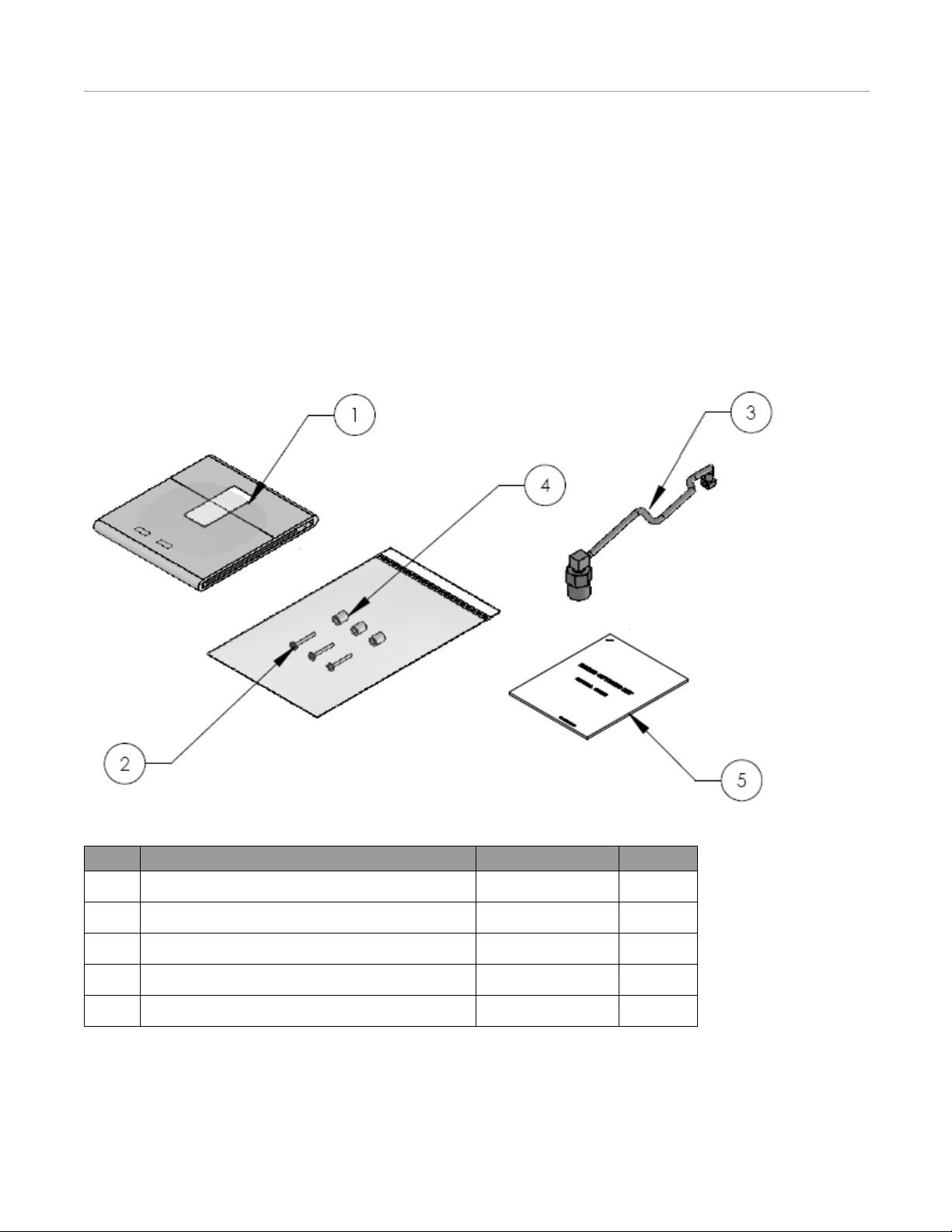
OmniSTAR Receiver Kit
Figure 3-1 OmniSTAR Receiver Kit Components (PN: 200-0504-02)
T able 3-1 Installation Kit Components (PN: 200-0504-02)
Item Component Part Number Quantity
1. OmniSTAR Receiver 300-0082-01 1
2. Screw, M2 x 14mm 515-0070-01 3
3. OmniSTAR Cable 201-0418-02 1
4. Spacer 521-0032-01 3
5. Installation Manual 602-0249-04 1
10 Radio Option Kits
Page 17
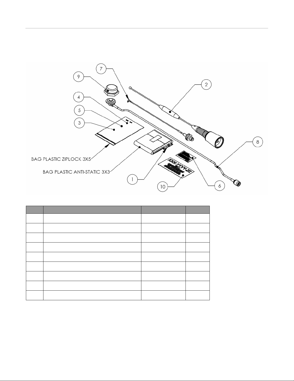
900 MHz Radio Modem Kit
Figure 3-2 900 MHz Radio Modem Kit Components (PN: 200-0505-04)
900 MHz Radio Modem Kit
Table 3-2 Installation Kit Components (PN: 200-0505-04
Item Component Part Number Quantity
1. 900 MHz MM2 Radio Modem 500-0410-01 1
2. 900 MHz Antenna 500-0262-01 1
3. Screw, M2 x 14mm 515-0070-01 3
4. Standoff Saddle 510-0177-01 2
5. Spacer 521-0032-01 4
6. FCC Compliance Label 603-0278-03 1
7. Internal Coax Cable with MMCX Connector 201-0510-01 1
8. ParaDyme Housing to Whip Coax Cable 201-0423-01
9. NMO Cap 510-0087-01 1
Hardware Installation Guide 11
Page 18

UHF Radio Modem Kits
UHF Radio Modem Kits
There are three versions of the UHF Radio Modem kits. The components in these kits are identical except for the antennas.
The differences in the antennas are shown in Table 3-3.
Table 3-3 UHF Radio Modem Kit Antennas
Kit Antenna MHz
200-0578-04 500-0093-02 406-430
200-0579-04 500-0094-02 430-450
200-0506-04 500-0095-02 450-470
Figure 3-3 UHF Radio Modem Kit Components (PNs: 200-0506-04, 200-0578-04, 200-0579-04)
T able 3-4 Installation Kit Components (PNs: 200-0506-02, 200-0578-02, 200-0579-02)
Item Component Part Number Quantity
1. Ribbon Cable 201-0401-01 1
2. Radio Mounting Bracket 202-0248-01 1
3. UHF Radio Module 500-0348-01 1
4. Antenna See Table 3-3 1
5. Screw, M3 x 5mm 515-0072-01 4
6. Screw, 4/40 x 3/8 514-0112-01 2
7. Screw, M2.5 x 4mm 515-0068-01 4
8. Cable Tie 510-0078-01 2
9. ParaDyme Housing to Whip Coax Cable 201-0423-01 1
10. Internal Coax Cable with MCX Connector 201-0399-01 1
11. NMO Cap 510-0087-01 1
12 Radio Option Kits
Page 19

VHF Radio Modem Kits
Figure 3-4 VHF Radio Modem Kit Components (PN: 200-0590-04)
VHF Radio Modem Kits
Table 3-5 Installation Kit Components (PN: 200-0590-04)
Item Component Part Number Quantity
1. Ribbon Cable 201-0401-01 1
2. Radio Mounting Bracket 202-0248-01 1
3. VHF Radio Module 500-0408-01 1
4. Antenna 500-0409-02 1
5. Screw, M3 x 5mm 515-0072-01 4
6. Screw, 4/40 x 3/8 514-0112-01 2
7. Screw, M2.5 x 4mm 515-0068-01 4
8. Cable Tie 510-0078-01 2
9. ParaDyme Housing to Whip Coax Cable 201-0423-01 1
10. Internal Coax Cable with MCX Connector 201-0399-01 1
11. NMO Cap 510-0087-01 1
Hardware Installation Guide 13
Page 20

VHF Radio Modem Kits
14 Radio Option Kits
Page 21

WiFi Antenna
Radio Modem Antenna
Cell Modem Antenna
Radio Modem Kits Installation
This Radio Modem Kits Installation chapter contains information in the following sections:
• Preparation
• Changing or Installing a SIM Card
• OmniSTAR Receiver Kit Installation Procedure (200-0504-02 Kit)
• 900 MHz RTK Radio Modem Kit Installation Procedure (200-0505-04 Kit)
• UHF and VHF Radio Modem Kit Installation Procedure
• ParaDyme Smart Antenna Bottom Cover Installation Procedure
• Antenna Installation Procedure
Preparation
4
1. If the Roof Module is installed on a vehicle, remove it from the vehicle.
2. If the Roof Module has a whip radio modem antenna and/or WiFi antenna already attached to it, remove them. The cell
phone antenna can remain attached.
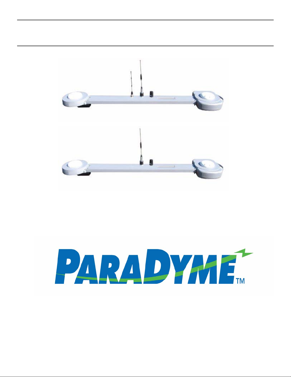
Note: ParaDyme Roof Modules with Part Number 200-0473-02 or lower will have three antennas as shown in
Figure 4-1. If the ParaDyme Roof Module has a Part Number of 200-0473-03 or later, it will no longer have the WiFi
Antenna.
Figure 4-1 Antennas Identified on Roof Module
Hardware Installation Guide 15
Page 22

Preparation
ParaDyme Smart Antenna Bottom Cover
3. Place the Roof Module upside down on a flat bench. Use the original packing material, wood spacers, or some other block
under the Roof Module at each end to stabilize the unit to prevent damage to the GPS and cell phone antennas as shown in
Figure 4-2
Figure 4-2 Figure 4-2 ParaDyme Receiver
4. Clean the Roof Module with a damp cloth to remove any debris.
5. Using a #2 Phillips screwdriver, remove the 13 screws holding the cover to the bottom of the ParaDyme Smart Antenna.
Figure 4-3 Remove Bottom Cover Screws from ParaDyme Smart Antenna
16 Radio Option Kits
Page 23

UHF/VHF Radio Module Mounting Location
900 MHz Radio Module Mounting Location
OmniSTAR Module Mounting Location
Cell Modem Location
SIM Card Mounting Location
6. Remove the ParaDyme Smart Antenna bottom cover to access the component mounting locations.
Figure 4-4 Cover Removed and Component Mounting Locations Identified
Preparation
Note: This figure shows only the Cell Modem installed. Depending on which options have been already installed,
your Roof Module may appear different than the figure.
Note: The Cell Modem installed in your ParaDyme may be different than the one shown in the figure.
Note: Always wear an electrostatic discharge wrist strap when handling a printed circuit board. Failure to use an
electrostatic discharge wrist strap may cause permanent damage to the printed circuit board and void the warranty.
7. Refer to one or more of the following sections for instructions on installing your kit or kits.
• Changing or Installing a SIM Card on page 18
• OmniSTAR Receiver Kit Installation Procedure (200-0504-02 Kit) on page 21
• 900 MHz RTK Radio Modem Kit Installation Procedure (200-0505-04 Kit) on page 24
• UHF and VHF Radio Modem Kit Installation Procedure on page 32
Hardware Installation Guide 17
Page 24

Changing or Installing a SIM Card
SIM Card Slot in the Closed Position
SIM Card Holder Unlatched
Changing or Installing a SIM Card
1. Locate the SIM Card holder on the circuit board.
Note: The SIM Card slot may already have a factory Installed SIM Card installed in it. These instructions can also be
used to change the SIM Card if that is necessary.
Figure 4-5 SIM Card Slot
2. Carefully slide the plastic SIM Card holder to the left 1/8" (3 mm) with your finger.
Figure 4-6 SIM Card Slot Unlocked
18 Radio Option Kits
Page 25

Changing or Installing a SIM Card
Corner Notch in Proper Position
Metal Contacts Face Up
3. Flip the upper plastic retainer open. If a SIM card is already installed and needs to be removed, it can be removed by
sliding it out of the retainer clip to the left.
Figure 4-7 SIM Slot Opened
4. Slide the new SIM card into the retainer clip.
Note: The metal contacts need to be face up and the corner of the SIM card with the notch in it needs to be positioned
as shown.
Figure 4-8 SIM Card Inserted
Hardware Installation Guide 19
Page 26

Changing or Installing a SIM Card
Retainer in Locked Position
5. Flip the SIM card retainer back over and then slide it to the right into the locked position.
Figure 4-9 SIM Card Installed
6. If the installation is complete, go to the ParaDyme Smart Antenna Bottom Cover Installation Procedure on page 41.
7. If other radios that require a Radio Modem or another antenna have been installed on the system: first reinstall the
ParaDyme Smart Antenna Bottom Cover, and then attach the required antennas to the Roof Module as shown in the
Antenna Installation Procedure on page 44.
20 Radio Option Kits
Page 27

OmniSTAR Receiver Kit Installation Procedure (200-0504-02 Kit)
Mounting Screw Locations
OmniSTAR Receiver Kit Installation Procedure
(200-0504-02 Kit)
1. Locate and remove the three existing M2 x 5mm screws holding the circuit board to the OmniSTAR mounting hole
locations with a #0 Philips screwdriver. See Figure 4-10.
Figure 4-10 OmniSTAR Mounting Screw Locations
2. Place the three spacers on top of the three screw holes.
Figure 4-11 Spacers Installed
Hardware Installation Guide 21
Page 28

OmniSTAR Receiver Kit Installation Procedure (200-0504-02 Kit)
OmniSTAR Circuit Board
Screws
3. Mount the OmniSTAR printed circuit board taking care to verify that all the pins line up.
Note: Failure to line up the pins could cause damage to the circuit board and invalidate the warranty.
Figure 4-12 Verify Pins Line up when Attaching OmniSTAR Circuit Board
4. Attach the OmniSTAR circuit board with three M2 x 14mm screws provided. Torque the three screws to 2 in-lb (0.2
Newton meters) with a #0 Phillips driver.
Figure 4-13 OmniSTAR Circuit Board Installed
22 Radio Option Kits
Page 29

OmniSTAR Receiver Kit Installation Procedure (200-0504-02 Kit)
MCX Connector
SMA Connector
5. Loosely attach the SMA connector of the OmniSTAR cable to the connector shown in Figure 4-14.
6. Secure the MCX end connector to the OmniSTAR board. The MCX connector should snap into place.
7. Return to the SMA connector and torque the hexagonal nut to 8 in-lb (0.9 Newton meters) with an 8mm open end wrench.
Figure 4-14 OmniSTAR Cable Routing
8. If the installation is complete, go to the ParaDyme Smart Antenna Bottom Cover Installation Procedure on page 41.
9. If other radios that require a Radio Modem or another antenna have been installed on the system: first reinstall the
ParaDyme Smart Antenna Bottom Cover, and then attach the required antennas to the Roof Module as shown in the
Antenna Installation Procedure on page 44.
Hardware Installation Guide 23
Page 30

900 MHz RTK Radio Modem Kit Installation Procedure (200-0505-04 Kit)
Plastic Plug
Wire Guide
900 MHz RTK Radio Modem Kit Installation Procedure
(200-0505-04 Kit)
Note: Steps 1 through 5 can be skipped for ParaDyme units with Part Number 200-0473-02 or earlier.
1. Remove the wire guide from the back of the Roof Module cross beam.
2. Remove the plastic plug from the central hole in the cross beam next to the cell phone antenna with a flat screwdriver.
Figure 4-15 Remove Wire Guide and Plug
24 Radio Option Kits
Page 31

900 MHz RTK Radio Modem Kit Installation Procedure (200-0505-04 Kit)
Antenna Connector
Antenna Connector Retainer
3. Insert the antenna connection of the external coax cable through the hole where the plug was removed.
Figure 4-16 Install External Antenna Cable
4. Verify that the coax cable is pointed to the Smart Antenna and fits behind the existing cell modem antenna coax. Connect
the antenna connector to the cross beam using the antenna connector retainer. Torque the retainer to 55 in-lbs (6.2 Newton
meters) with a 12mm and 24mm wrenches.
Figure 4-17 Antenna Connector Secured
Hardware Installation Guide 25
Page 32

900 MHz RTK Radio Modem Kit Installation Procedure (200-0505-04 Kit)
Radio Modem Coax Access Port Plug
5. Remove the plug from the ParaDyme Smart Antenna housing for the radio coax connectors with an 8mm Allen wrench.
Figure 4-18 Remove Plug
Note: For ParaDyme systems with Part Number 200-0473-02 or earlier, the exiting coax cable that was installed will
need to be removed and replaced with the cable shown in Step 6, because the cable ends that connect to the radio
modem are different. Once the existing cable has been removed, continue to Step 6.
26 Radio Option Kits
Page 33

900 MHz RTK Radio Modem Kit Installation Procedure (200-0505-04 Kit)
Internal Coax Cable Attached
6. Attach the bulkhead adapter connector of the internal coax cable to the housing of the ParaDyme Smart Antenna.
Note: Verify that the lock washer is on the outside of the housing before attaching the nut. Do not tighten the
connector at this time.
Figure 4-19 Attach Internal Coax Cable to Housing
7. Locate the Freewave MM2 mounting position on the circuit board and the four screw attachment points. See Figure 4-20.
Figure 4-20 900 MHz Radio Modem Installation Location
Hardware Installation Guide 27
Page 34

900 MHz RTK Radio Modem Kit Installation Procedure (200-0505-04 Kit)
Spacers
8. Place four spacers on top of the existing screw holes.
Figure 4-21 Install Spacers
9. Align the 900 MHz radio modem and insert the pins into the J3 header as shown in Figure 4-22.
Note: Exercise care when installing the 900 MHz radio. The pins in the connector must be properly aligned and not
bent during the installation. Failure to line up the pins could cause damage to the circuit board and invalidate the
warranty.
Figure 4-22 Verify Pins Line up when Attaching 900 MHz Circuit Board
28 Radio Option Kits
Page 35

900 MHz RTK Radio Modem Kit Installation Procedure (200-0505-04 Kit)
Standoff Saddles
10.Attach the 900 MHz radio modem with four M2 x 14mm screws. Torque the three screws to 2 in-lb (0.2 Newton meters)
with a #0 Phillips driver.
Figure 4-23 900 MHz Radio Modem Installed
11. Insert two standoff saddles in the existing holes on the circuit board at locations labeled MP2 and MP3.
Figure 4-24 Standoff Saddle Mounting Holes Location
Hardware Installation Guide 29
Page 36

900 MHz RTK Radio Modem Kit Installation Procedure (200-0505-04 Kit)
Cable Clamps
Internal Coax Cable
Attachment of Internal Coax Cable to Radio
Saddle Standoffs
12. Remove the two cable clamps shown in Figure 4-25 with a #1 Phillips screwdriver. Route the internal coax cable through
these cable clamps and then reattach them.
Note: Verify that the cable clamp loops are facing the same direction (down) as shown in Figure 4-25 after they are
reattached, otherwise the cover will not fit properly. The internal coax cable(s) must be attached so that they pass
between the two cable clamps or they will be damaged when the cover is reinstalled.
Figure 4-25 Internal Coax Cable Secured by Cable Clamps
13. Attach the end of the internal coax cable to the 900 MHz radio.
14. Secure the cable into the standoff saddles as shown in Figure 4-26.
Figure 4-26 Internal Coax Cables Secured
30 Radio Option Kits
Page 37

900 MHz RTK Radio Modem Kit Installation Procedure (200-0505-04 Kit)
Bulkhead Adapter
Antenna Coax Cable
Wire Guide Replaced
15.Tighten the bulkhead connector with a 5/8" open end wrench. Verify that the nut is tight and the hole is water tight.
16.Attach the antenna coax cable to outside connector of the bulkhead adapter. Do not over tighten.
Figure 4-27 External Coax Cables Attached and Bulkhead Adapter Tightened
17.Replace the wire guide to the back of the cross arm.
Figure 4-28 Replace Wire Guide
18.If the installation is complete, go to the ParaDyme Smart Antenna Bottom Cover Installation Procedure on page 41.
19.After reinstalling the ParaDyme Smart Antenna Bottom Cover, attach the required antennas to the Roof Module as shown
in the Antenna Installation Procedure on page 44.
Hardware Installation Guide 31
Page 38

UHF and VHF Radio Modem Kit Installation Procedure
Wire Guide
Plastic Plug
UHF and VHF Radio Modem Kit Installation Procedure
(UHF 200-0506-04, 200-0578-04, and 200-0579-04 Kits)
(VHF 200-0590-04 Kit)
Note: Steps 1 through 5 can be skipped for ParaDyme Part Number 200-0473-02 or earlier.
1. Remove the wire guide from the back of the Roof Module cross beam.
2. Remove the plastic plug from the central hole in the cross beam next to the cell phone antenna with a flat screwdriver.
Figure 4-29 Remove Wire Guide and Plug
32 Radio Option Kits
Page 39

UHF and VHF Radio Modem Kit Installation Procedure
Antenna Connector
Antenna Connector Retainer
3. Insert the antenna connection of the external coax cable through the hole where the plug was removed.
Figure 4-30 Install External Antenna Cable
4. Verify that the coax cable is pointed to the Smart Antenna and fits behind the existing cell modem antenna coax. Connect
the antenna connector to the cross beam using the antenna connector retainer. Torque the retainer to 55 in-lbs (6.2 Newton
meters) with a 12mm and 24mm wrenches.
Figure 4-31 Antenna Connector Secured
Hardware Installation Guide 33
Page 40

UHF and VHF Radio Modem Kit Installation Procedure
Radio Modem Coax Access Port Plug
Remove Screws
5. Remove the plug from the ParaDyme Smart Antenna housing for the radio coax connectors with an 8mm Allen wrench.
Figure 4-32 Remove Plug
6. Remove the four screws on the back of the UHF or VHF Radio shown in Figure 4-33 with a #1 Philips screwdriver.
Figure 4-33 Remove screws from UHF or VHF Radio
34 Radio Option Kits
Page 41

UHF and VHF Radio Modem Kit Installation Procedure
Verify Tab Position
7. Attach the bracket to the UHF or VHF Radio Modem with four M2.5 x 4mm screws provided. Torque the screw to 2 in-lb
(0.2 Newton meters). See Figure 4-34.
Note: Verify that the bracket is attached as shown with the attachment tabs orientated down. If the bracket is inverted,
it will interfere with the bottom cover.
Figure 4-34 UHF or VHF Radio with Mounting Bracket
8. Locate the mounting position on the ParaDyme Smart Antenna for the UHF or VHF radio shown in Figure 4-35.
Figure 4-35 UHF or VHF Radio Mounting Location
Hardware Installation Guide 35
Page 42

UHF and VHF Radio Modem Kit Installation Procedure
Attach with Screws
Attach with Screws
9. Mount the UHF or VHF radio and bracket on the ParaDyme receiver with four M3 x 5mm screws. Torque the screws to 5
in-lb (0.6 Newton meters) with a #1 Phillips screwdriver. See Figure 4-36.
Figure 4-36 UHF or VHF Radio Modem Installed
10. Attach the ribbon cable to the UHF or VHF Radio Modem with two 4/40 x 3/8 screws. Torque the screws to 5 in-lb (0.6
Newton meters) with a #1 Phillips screwdriver.
Figure 4-37 UHF or VHF Radio Modem Installed
36 Radio Option Kits
Page 43

UHF and VHF Radio Modem Kit Installation Procedure
90 Degree Fold
Casting Depression Location
11. Connect the other end of the ribbon data cable to J6 connector on the circuit board as shown in Figure 4-38.
Figure 4-38 Data Cable Routing
12.There is a slight depression in the bottom of the ParaDyme casting between where the UHF or VHF radio and circuit board
are mounted. Carefully fold the ribbon cable down so that it touches the casting in this depression. Keep the ribbon cable
held down at the casting, and then fold it around the top part of the UHF or VHF radio. Finally, fold the ribbon cable at a 90
degree angle on top of the UHF or VHF radio as shown in Figure 4-40.
Figure 4-39 Ribbon Cable Arrangement
Note: When reattaching the bottom cover, there is a reinforcement wall molded into the cover between the circuit
board and the UHF or VHR radio mounting location with a slight gap to allow the ribbon cable to pass from one side
to the other. This is shown in Figure Figure 4-40. If the ribbon cable is not routed properly, it can be crushed or
broken when the cover is reattached. To prevent this type of damage, the ribbon cable must be folded and positioned
as shown in Figure 4-40. A piece of tape can be used to hold the ribbon cable in place on top of the UHF or VHF
radio until the cover is reattached.
Hardware Installation Guide 37
Page 44

UHF and VHF Radio Modem Kit Installation Procedure
Reinforcement Wall
Gap for Ribbon Cable
Bulkhead Adapter
UHF or VHF Radio Connector
Figure 4-40 Bottom Cover
Note: For ParaDyme systems with Part Number 200-0473-02 or earlier, the exiting coax cable that was installed with
the ParaDyme unit can be used and does not need to be replaced. Step 14 can be skipped below.
13. Attach one end of the VHF or UHF internal coax cable to the VHF or UHF radio.
14. Attach the bulkhead adapter connector of the internal coax cable to the housing of the ParaDyme Smart Antenna as shown
in Figure 4-41. Tighten the bulkhead adapter with a 5/8" open end wrench. Verify that the nut is tight and the hole is water
tight.
Note: Verify that the lock washer is on the outside of the housing before attaching the nut.
Figure 4-41 Coax Cable Connected
38 Radio Option Kits
Page 45

UHF and VHF Radio Modem Kit Installation Procedure
Coil and Secure
Bulkhead Adapter
Antenna Coax Cable
15.Coil the internal coax cable into a small circular bundle and use cable ties to secure it. See Figure 4-42.
Figure 4-42 Coax Cable Routing
16.Attach the antenna coax cable to outside connector of the bulkhead adapter. Do not over tighten.
Figure 4-43 External Coax Cables Attached and Bulkhead Adapter Tightened
Hardware Installation Guide 39
Page 46

UHF and VHF Radio Modem Kit Installation Procedure
Wire Guide Replaced
17. Replace the wire guide on the back of the cross arm.
Figure 4-44 \Replace Wire Guide
18. If the installation is complete, go to the ParaDyme Smart Antenna Bottom Cover Installation Procedure on page 41.
19. After reinstalling the ParaDyme Smart Antenna Bottom Cover, attach the required antennas to the Roof Module as shown
in the Antenna Installation Procedure on page 44.
40 Radio Option Kits
Page 47

ParaDyme Smart Antenna Bottom Cover Installation Procedure
ParaDyme Receiver Bottom
Section Gasket and Grove
ParaDyme Smart Antenna Bottom Cover Installation
Procedure
1. Inspect the ParaDyme Smart Antenna bottom section gasket for defects. If you find it is damaged, pinched, or permanently
deformed, replace the gasket (PN 507-0006-01). Contact your dealer for a replacement. See Figure 4-45.
Note: Figure 4-45 shows only one possible configuration of the ParaDyme Roof Module. Depending on what options
and equipment are installed, your system may appear different than the picture. In all cases, the gasket and groove will
be located in the same location.
2. Inspect the groove around the gasket for cleanliness and defects that could damage the gasket. See Figure 4-45.
Figure 4-45 ParaDyme Receiver Bottom Section Gasket (PN 507-0006-01)
3. Verify that all the coax and ribbon cables and cable clamps are routed and installed as instructed. Coax cables from the
bulkhead adapters to the circuit board must be secured between the two wire clamps. If a ribbon cable is connected to a
UHF or VHF radio, the cable must be folded and routed to pass through recess as described in the installation instructions.
Note: Failure to ensure the coax and ribbon cables are routed properly may cause them to be pinched and or damaged
when the bottom is reattached.
Hardware Installation Guide 41
Page 48

ParaDyme Smart Antenna Bottom Cover Installation Procedure
Internal Walls
Flat Area
4. Inspect the bottom cover and verify that the flat area where the gasket will touch is clean and free of defects.
Note: Notice the internal walls on the bottom cover. Prior to installing the cover, verify no cables will be pinched by
the walls when it is attached.
Figure 4-46 ParaDyme Receiver Bottom Section Groove Inspection
5. Place the bottom cover on the ParaDyme receiver using the screw holes to guide the cover into the proper position.
6. Verify that the bottom cover is seated properly; there should be a small uniform gap along the seam between the cover and
the ParaDyme receiver.
Note: Make sure the gasket seats properly in its groove and does not get squeezed between the base and the cover.
Note: Ensure that the mating surfaces are clean.
7. Refer to Figure 4-47 for hole number identifications for the following steps.
8. Install three M5 x 12mm screws loosely into holes 5, 7, and 9.
9. Install two M5 x 55mm screws loosely into holes 13 and 10.
10. Install eight M5 x 45mm screws loosely in the remaining holes.
42 Radio Option Kits
Page 49

ParaDyme Smart Antenna Bottom Cover Installation Procedure
1
3
7
5
9
12
4
10
11
13
2
8
6
11. Tighten the screws to 20 in-lb (2.3 Newton meters) with a #2 Phillips driver following the numbered sequence (1-13)
shown in Figure 4-47.
Figure 4-47 ParaDyme Receiver Bottom Cover Installation
12. Repeat the torque pattern to ensure all screws are properly secured.
13. Go to the Antenna Installation Procedure on page 44.
Hardware Installation Guide 43
Page 50

Antenna Installation Procedure
Antenna Installation Procedure
WARNING
To avoid electrical shock hazards, remove the Roof Module
from the vehicle before driving under low structures or low
electrical power lines.
1. Flip the Roof Module back into the upright position.
2. Attach the required whip antennas to the proper Roof Module antenna connections. See Figure 4-48.
Note: A threaded plastic NMO cap is provided to protect the VHF/UHF antenna base when the whip antenna is not
installed. Always install the NMO cap when transporting or shipping the ParaDyme system without a VHF/UHF
antenna.
Note: Hand tighten the connections to ensure a good waterproof seal and electrical continuity. Do not over tighten.
Note: Figure 4-48 shows the location of the three possible antennas. Roof Modules with Part Number 200-0473-02 or
earlier have a WiFi antenna that needs to be installed. Roof Modules with Part Number 200-0473-03 and later no
longer have this antenna and instructions pertaining to it can be ignored.
Note: Make sure the antenna O-ring seats properly in its groove and does not get squeezed between the antenna base
and the Roof Module extrusion. See Figure 4-49.
44 Radio Option Kits
Page 51

WiFi Antenna
Radio Modem Antenna
Cell Modem Antenna
Figure 4-48 Attach the Antennas
Figure 4-49 Antenna O-ring
Antenna Installation Procedure
3. Refer to the Hardware Installation Manual to install the Roof Module on the vehicle.
4. Refer to the ParaDyme Owner’s Manual for further instructions on setting up OmniSTAR corrections, selecting a 900
MHz Base Station channel, and/or selecting the Base Station frequency for the UHF 4XX MHz or VHF 16X MHz radio
modems.
5. If using a 16X MHz or 4XX MHz UHF and VHF whip antenna, the antenna must be cut to the proper length to match the
frequency the radio will be using.
a. Refer to one of the following tables to ascertain the proper length for the antenna and frequency being used.
b. Loosen the two set screws at the base of the antenna using a 3/32" Allen wrench, and then remove the antenna from
the base.
c. Measure the antenna and mark the proper length using the diagram next to the table as a guide.
d. Cut the end of the whip with a hacksaw.
Hardware Installation Guide 45
Page 52

Antenna Installation Procedure
e. Reinstall the whip on the antenna base and tighten the two set screws. Ensure that the whip fits all the way into the
base before tightening.
Table 4-1 UHF 406-430 MHz Antennas (500-0093-02)
406-430 MHz
No Cutting Necessary
Table 4-2UHF 430-450 MHz Antennas (500-0094-02)
MHz Inches mm
430 12.750 324
435 12.188 310
440 11.625 295
445 11.000 279
450 10.563 268
Table 4-3UHF 450-470 MHz Antennas (500-0095-02)
MHz Inches mm
450 10.000 254
455 9.625 244
460 9.188 233
465 8.938 227
470 8.563 217
46 Radio Option Kits
Page 53

Antenna Installation Procedure
Table 4-4VHF 144-174 MHz Antennas (500-0409 -02)
MHz Inches mm
144 40.750 1035
146 39.500 1003
148 38.500 978
150 37.000 940
152 36.000 914
154 35.000 889
156 34.000 864
158 33.000 838
160 32.000 813
162 31.000 787
164 30.250 768
166 29.500 749
168 29.000 737
170 28.500 724
172 27.750 705
Hardware Installation Guide 47
Page 54

Antenna Installation Procedure
48 Radio Option Kits
 Loading...