


ParaDyme
Table of contents
 Loading...
Ag Leader PN 4002139 Rev G

© 2013 Ag Leader Technology
2202 South Riverside Drive
Ames, Iowa 50010 USA
All Rights Reserved
Ag Leader Integra and Versa Firmware Version 4.3 / Edge Firmware Version 5.1

Table of Contents
T
ABLE
Paradyme
Legal Disclaimer .......................................................................................................5
Important Information.....................................................................................5
Introduction...............................................................................................................5
Display Harness Diagram.........................................................................................6
Steering Harness Diagram .......................................................................................7
Safety and Regulatory Requirements.......................................................................8
FCC Requirements .............................................................................................8
European Requirements .....................................................................................8
Regulatory Information........................................................................................9
RF Exposure Information ....................................................................................9
Accessing the AutoSteer Setup Screen..............................................................9
From Ag Leader Integra or Versa..................................................................9
From EDGE Display ....................................................................................10
Initial Setup .......................................................................................................10
AutoSteer Setup Screen Overview ...................................................................11
Base Station......................................................................................................11
LED Status........................................................................................................11
GPS Corrections ...............................................................................................12
Using the Vehicle Menu..........................................................................................12
Accessing the Vehicle Menu.............................................................................12
Setup Wizard.....................................................................................................13
Initial Create Vehicle Procedure (First Time Use) .......................................13
Standard Create Vehicle Procedure ............................................................14
Manage Vehicle ................................................................................................18
Select the Active Vehicle .............................................................................18
Edit Vehicle..................................................................................................18
Delete Vehicle..............................................................................................20
Auto Calibrate ...................................................................................................20
Adjust Lateral Offset ....................................................................................23
Steering Adjust..................................................................................................24
Steering Adjust Screen ................................................................................24
Steering Components .......................................................................................24
Roof Module ................................................................................................24
SA Module (Sensor Actuator Module) .........................................................25
Hydraulic Valve............................................................................................25
Manual Steering Override (Autosteering Kick-out Limit Adjustment)...........26
Autocal Steering Override Adjustment.........................................................26
Adjusting Manual Steering Override ............................................................27
Adjusting Samples Required setting............................................................27
Manual Steering Override Adjustment.........................................................28
Gyro.............................................................................................................28
Wheel Angle Sensor....................................................................................29
Using the System Menu .........................................................................................29
Overview ...........................................................................................................29
OF
C
ONTENTS
1

System Health .................................................................................................. 29
Manage Settings............................................................................................... 30
Log File ....................................................................................................... 30
Database..................................................................................................... 31
Database Backup Procedure............................................................................ 32
To backup a database:................................................................................ 32
Database Restore Procedure ........................................................................... 32
To restore a database: ................................................................................ 32
Reset Factory Default ................................................................................. 32
Accessories ...................................................................................................... 33
Remote Engage Switch (RES).................................................................... 33
Technician ........................................................................................................ 33
Software Upgrade............................................................................................. 33
Upgrade Via Roof Module USB .................................................................. 34
Upgrade Via the Display USB ..................................................................... 35
Upgrade Via WiFi Using a PC..................................................................... 36
Using the GPS Menu ............................................................................................. 37
Overview........................................................................................................... 37
RTK .................................................................................................................. 38
General ....................................................................................................... 38
Change Channel ......................................................................................... 39
Changing the 900 MHz Radio Channel ................................................. 39
Changing the AFLink Radio Frequency................................................. 40
RTK Connection Type................................................................................. 41
Throughput.................................................................................................. 42
Base Satellites ............................................................................................ 42
Base Location ............................................................................................. 42
Using the Base Location Update Function ............................................ 43
Using the Update Saved Location Procedure........................................ 43
OmniSTAR ....................................................................................................... 44
OmniSTAR Background Information........................................................... 44
OmniSTAR Options..................................................................................... 45
General ....................................................................................................... 45
Accuracy ..................................................................................................... 45
Channel....................................................................................................... 46
WAAS ............................................................................................................... 46
WAAS Background Information .................................................................. 46
WAAS PRN Number Selection ................................................................... 46
Precision Settings............................................................................................. 47
NTRIP............................................................................................................... 48
General ....................................................................................................... 49
Profile.......................................................................................................... 49
Planning Tool.................................................................................................... 50
General ....................................................................................................... 50
Sky Plot ....................................................................................................... 51
Forecast ...................................................................................................... 51
GPS Diagnostics .............................................................................................. 51
General ....................................................................................................... 52
Satellite Tracking......................................................................................... 52
2 Ag Leader Integra and Versa Firmware Version 4.3 / Edge Firmware Version 5.1

NMEA Out........................................................................................................53
Port A Messages .........................................................................................53
Port A Configuration ....................................................................................54
Port B Messages and Configuration ............................................................54
Using the Connections Menu .................................................................................54
Cell Modem.......................................................................................................54
Cell Modem Screens (Factory-supplied SIM) ..............................................55
Cell Modem Screens (Customer-supplied SIM) ..........................................55
Change Carrier.......................................................................................56
Advanced Debug....................................................................................56
Configure SIM ........................................................................................57
WiFi ...................................................................................................................59
Configuring PC Settings for WiFi Connection..............................................59
Using the My Account Menu..................................................................................60
Overview ...........................................................................................................60
Call Support ......................................................................................................61
Details..........................................................................................................62
Feature Code...............................................................................................62
T
ABLE
OF
C
ONTENTS
3

4 Ag Leader Integra and Versa Firmware Version 4.3 / Edge Firmware Version 5.1

PARADYME
LEGAL DISCLAIMER
Notes:
• Read and follow ALL instructions carefully before installing or operating the AutoSteer system.
• Take careful note of the information in the Safety Requirements section.
The manufacturer disclaims any liability for damage or injury that results from failure to follow the
instructions and warnings set forth herein.
Please take special note of the following warnings:
1. There is NO obstacle avoidance system included in the manufacturer’s product. Therefore, users must
always have an operator on the equipment when the AutoSteer system is in use to look for any obstacles
including people, animals, trees, ditches, buildings, etc.
2. During installation of the AutoSteer system and during the Calibration and Tuning processes the
vehicle's wheels turn from side to side and the vehicle moves. Be sure that all people and obstacles are
clear of the vehicle before installation, calibration and tuning, or use of the AutoSteer system.
3. Use of the AutoSteer system is NOT permitted while equipment is on roads or in public areas. Follow
the instructions set forth below for ensuring that the system is OFF before driving on roads or in public
areas.
Important Information
Refer to your hardware installation manual for complete installation requirements before you start your
system.
INTRODUCTION
The ParaDyme system is a GPS and control system. It is at the heart of a full-featured precision
agriculture product and a vital element of an agriculture data management system. It is a precision
machine control and ease-of-use system that is a vital part of an integrated farm management system.
A few qualities of your ParaDyme system are:
• Intuitive Operation.
• Scalable GPS accuracies that cover North America, Australia and Europe. Hassle-free local corrections
(for repeatability).
• Scalable local correction sources with both 900MHz, 450MHz and cellular link options.
• Affordable; designed to provide more affordable performance steering.
• Full-featured; higher-end configurations offers a competitive menu of precision agriculture for
autosteering.
• Reliable; Two-way communications for diagnostics and software updates via cellular modem, or USB
storage device (user preference).
The following chapters explain how to perform the necessary tasks to enable your steering system. The
chapters feature descriptions of how to use the software to make your GPS a productive part of your
operation.
5
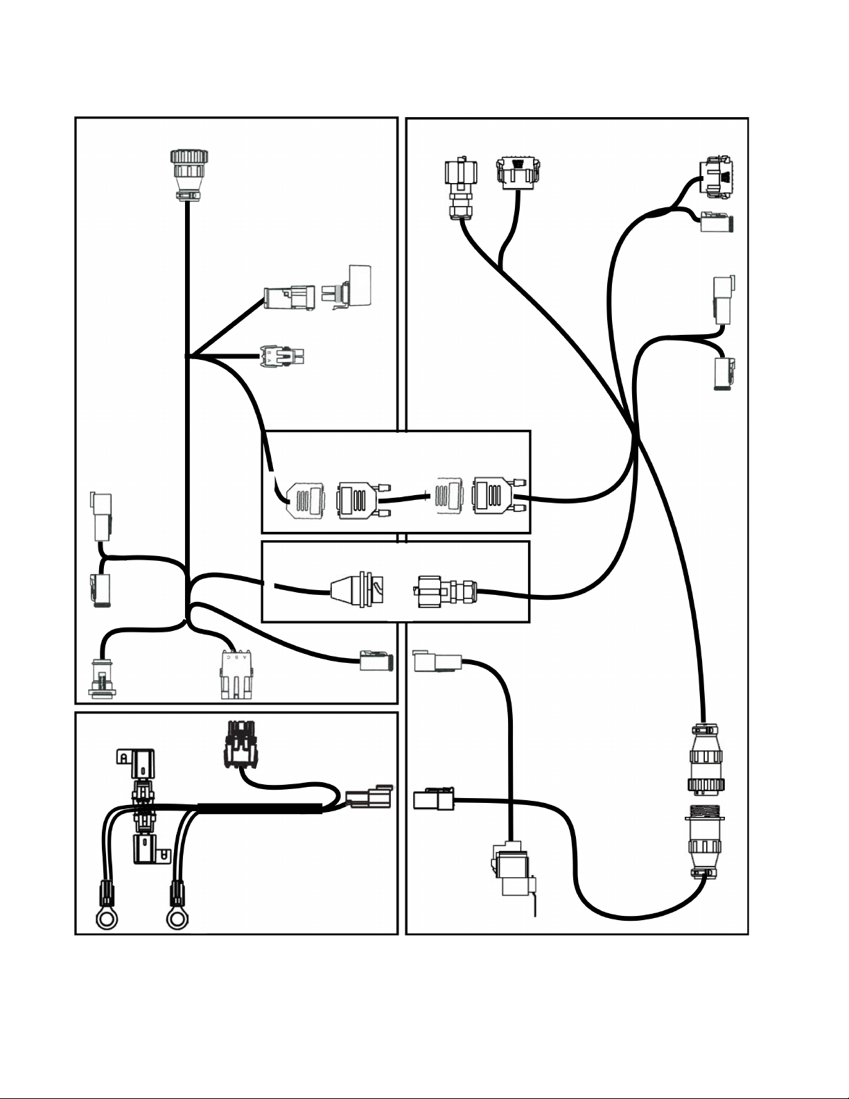
DISPLAY HARNESS DIAGRAM
Display
Harness
Display
Power Control Relay
Power Out
CAN B IN
4 pin
CAN B OUT
4 pin
CAN A
Power In
3 pin
Power
Harness
5 amp
15 amp
Vehicle +12 volts
Vehicle Ground
Guidance Power
4 pin
Constant
Power
Relay
Switched
Power
3 pin
EDGE ONLY
leave unattached for Ag Leader Integra/Versa
Null Modem
Ag Leader Integra or Versa ONLY
leave unattached for Edge display
CAN IN
4 pin
CAN OUT
4 pin
RJ45
12 pin
Ethernet
GPS Roof Module
SAM Data
12 pin
SAM Power
2 pin
2 pin
Ethernet
Serial
6 Ag Leader Integra and Versa Firmware Version 4.3 / Edge Firmware Version 5.1
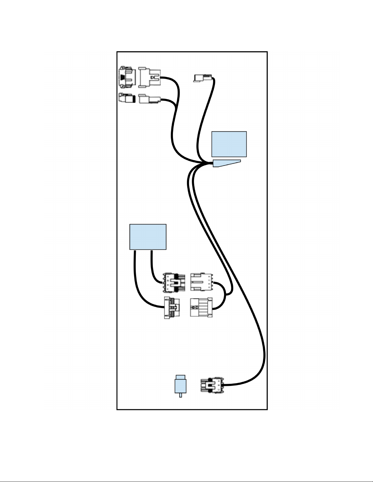
STEERING HARNESS DIAGRAM
SA Module
Wheel
Angle
Sensor
(Optional)
10 pin
SAM Data
12 pin
SAM Power
2 pin
3 pin
4 pin
70 pin
4 pin
AUTOSTEER
Val ve
Remote
Engage
7

SAFETY AND REGULATORY REQUIREMENTS
This Safety and Regulatory Requirements chapter provides information for the safe operation of the
ParaDyme system and for meeting regulatory compliancy. The ParaDyme system installer and
manufacturer disclaim any responsibility for damage or physical harm caused by failure to adhere to the
following requirements:
• The ParaDyme system must be operated by a trained and qualified operator.
• The operator must never leave the vehicle while the ParaDyme system is engaged.
• The ParaDyme system is not designed to replace the vehicle operator.
• The ParaDyme system does not detect obstacles in the vehicle path.
• When engaged, the ParaDyme system controls only the steering of the vehicle. The operator must control
the speed of the vehicle.
• The ParaDyme system should be turned off or disengaged when driving on public roads or anywhere other
than a farm field.
• Turn the ParaDyme system off or disengage when making adjustments to or changing towed or hitched
implements.
• The Roof Module must be removed when transporting the vehicle at speeds above 30 mph (50 kph).
FCC REQUIREMENTS
When operating in the United States, FCC licenses are required for AFLink radios.
This device is intended for use in the operation of commercial activities, educational, philanthropic, or
ecclesiastical institutions, and hospitals, clinics, or medical associations.
The Federal Communications Commission (FCC) requires you to have a license before you operate this
device. Unless you are already licensed to operate on one of the preset frequencies, you must apply for
a frequency through the PCIA (Personal Communication Industry Association), a non-profit organization
that assigns frequencies nationwide to help prevent conflicts between different businesses using
devices. In the same area. For more information about getting a license, contact the PCIA at 800-7590300, extension 3068 (in Virginia 703-739-0300, extension 3068).
For other questions concerning the license application, contact the FCC at 717-337-1212, or write: FCC
P.O. Box 1040
Gettysburg, PA 17325
For the latest FCC application form and instructions, call the FCC's fax-on demand service at 1-202-4180177 from a fax machine and request one or more of the following documents:
All forms and instructions 000600
If you do not have a fax machine, you can call the Government Forms Distribution Center at 1-800-418FORM and request that the form and instructions be mailed to you.
EUROPEAN REQUIREMENTS
When operating the ParaDyme system in Europe, contact your dealer to determine if additional licensing
is required.
8 Ag Leader Integra and Versa Firmware Version 4.3 / Edge Firmware Version 5.1
REGULATORY INFORMATION
The 802.11 b/g Radio module is installed in close proximity to other radio modules. This device complies
with Part 15 of the FCC Rules. This device shall be professionally installed and maintained by a trained
technician as directed by FCC regulations. Use of an antenna other than that outlined in the FCC and IC
certification filings for each of the radio products may violate FCC regulations. This device operation is
subject to the following two conditions:
1. It may not cause harmful interference.
2. It must accept any interference received, including interference that may cause undesired operation.
Manufacturer Description FCC ID (EUROPE/CANADA IC)
Novariant 802.11 b/g Radio TMN-WMIA-166AGI (8490A-WMIA-
166AGI)
Multi-Tech
Novariant
Intelligent Wireless1 Products Inc CDMA Single Channel RF Amplifier RFK-LMSWDJH819 (5252A-CA819)
TELIT Tri-Band UMTS/HSDPA Quad Band
SATEL Modem Receiver 403-470 MHz MRB-SATELTA10 (2422A-SATELTA10)
1
The Multitech radio drives the Intelligent Wireless Products amplifier and is used only in CDMA mode.
2
Whenever any Novariant Radio Module is mounted inside an enclosure, the enclosure must have a
1
2
CDMA MMC Modem AU792A04A22750 (125A-0010)
900 MHz FHSS Radio KNY-6231812519 (2329B-DGR09RAS)
R17UC864G (5131A-UC864G) [CE
GSM Modem
0984]
[CE 0523]
visual label on the outside featuring the module FCC ID.
RF EXPOSURE INFORMATION
CAUTION: This is a class A product. In a domestic environment this product may cause radio
interference in which case the user may be required to take adequate measures.
CAUTION: FCC RF Exposure Requirements Configuration 1 antenna must be mounted at least
26.6 cm away from nearby persons to comply to FCC RF exposure requirements.
Note: Configurations using radio modules not described above or which use antennas not qualified
for the radio modules above require further equipment authorization.
ACCESSING THE AUTOSTEER SETUP SCREEN
From Ag Leader Integra or Versa
1. Go to the Home Screen and press the Setup (wrench) button.
2. Press the GPS Setup button, as shown at left, and the GPS Setup Screen appears, as
shown below.
9
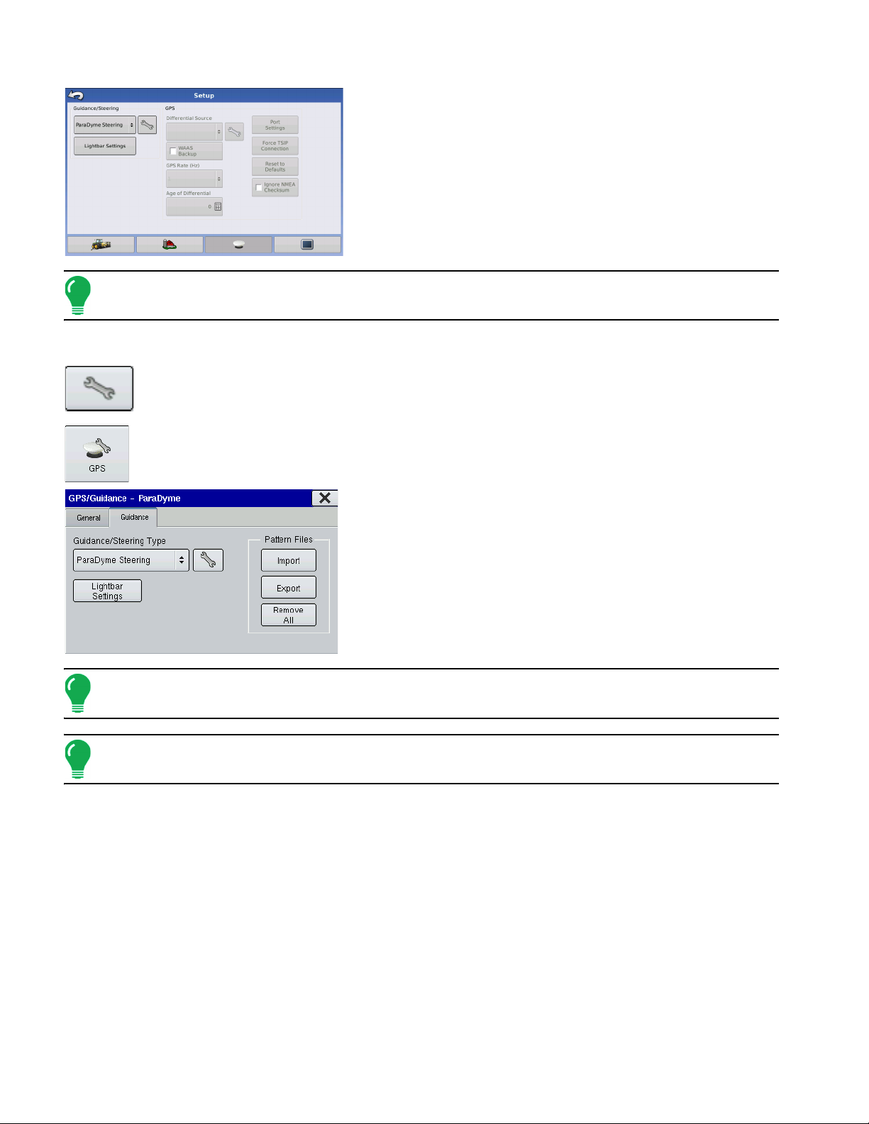
3. Under the Guidance/Steering drop-down menu, select
ParaDyme Steering.
4. The Liability Notice appears. Press the green check mark
button to accept.
5. Press the Setup (wrench) button on the Setup Screen to
begin ParaDyme operations.
Note:
In order for the User Display's Run Time Environment to be active, you must complete the initial configuration
steps as described in the Setup chapter of your display’s User Manual.
From EDGE Display
1. From the Home Screen, press the Setup (wrench) button to open the Setup screen.
2. At the Setup Screen, press the GPS Guidance icon, as shown at left.
3. Navigate to the Guidance Tab, as shown below.
4. Underneath the Guidance/Steering Type drop-down menu,
select ParaDyme Steering.
5. The Liability Notice appears. Press the green check mark
button to accept.
6. Press the Setup (wrench) button to begin ParaDyme
operations.
Note:
In order for the User Display's Run Time Environment to be active, you must complete the initial configuration
steps as described in the Setup chapter of your display’s User Manual.
Note: In order for the User Display's Run Time Environment to be active, you must complete the
initial configuration steps as described in the Setup chapter.
INITIAL SETUP
The steps listed below give an overview of procedures that must be successfully completed in order to
ensure proper ParaDyme system operation. See
1. Configure the radio channel to match your Base Station and configure your GPS options. See
the GPS Menu” on page 37
2. Create a new vehicle. See
.
“Setup Wizard” on page 13.
3. Calibrate the vehicle using the Calibration Wizard. See “Auto Calibrate” on page 20.
“Using the Vehicle Menu” on page 12 for details.
“Using
4. The system will perform a GPS survey, and then the vehicle will be ready to AutoSteer.
10 Ag Leader Integra and Versa Firmware Version 4.3 / Edge Firmware Version 5.1
• If your job requires an accurate latitude and longitude position, or the ability to repeat or continue a saved
job (Autosteer over the same guidance paths), refer to your Base Station Hardware Manual for additional
information and instructions.
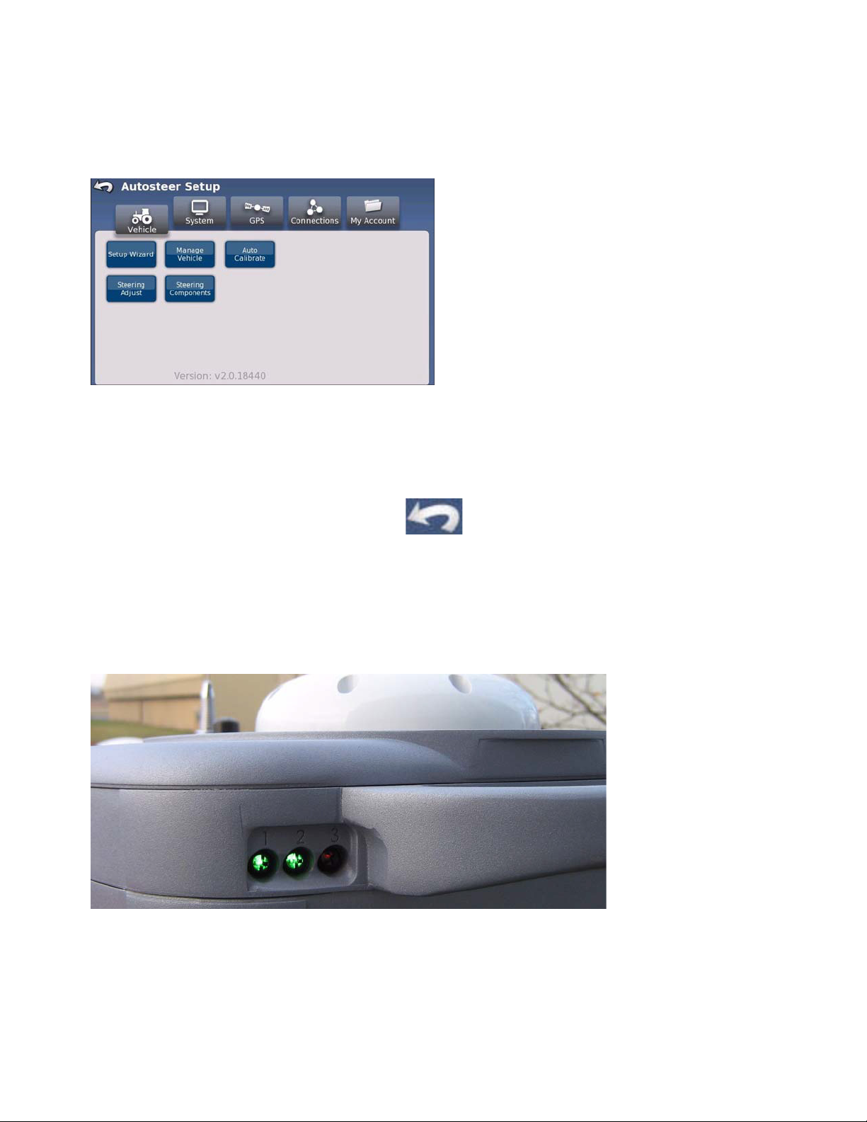
AUTOSTEER SETUP SCREEN OVERVIEW
The ParaDyme AutoSteer Setup Screen is
accessed from your display. Refer to your display's
User Manual for details.
• The
Vehicle
set up a new vehicle, manage existing vehicles, perform
the auto calibration of a vehicle, perform the steering
adjustments and manage steering components.
• The
System
monitor system parameters.
• The
GPS
information for selecting and configuring your GPS
correction source and radio options.
• The
Connections
• The
My Account
• To return to the previous screen, press the Back icon. Press the Back icon from the AutoSteer Setup
screen to return to your main application.
menu enables you to configure and monitor communication parameters.
menu enables you to configure and monitor account parameters.
menu enables you to configure a vehicle,
menu enables you to configure and
menu provides procedures and detailed
BASE STATION
If you use a base station, refer to your base station hardware manual for installation and operation
instructions.
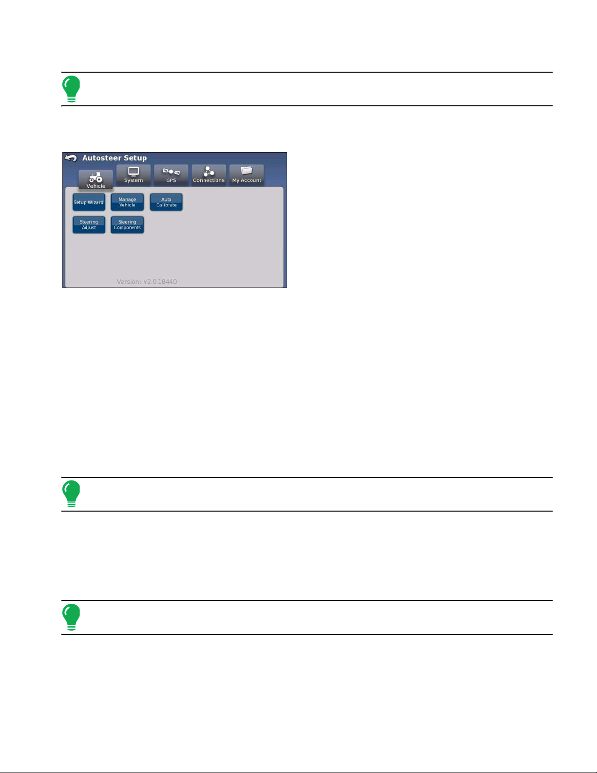
LED STATUS
Table 3-1 defines the
status of the system as
shown by the LEDs color
configuration.
11
Table 3-1LED Status.
LED
1 Off Orange/
2 Off Orange/
3 Off Orange/
Power
Off
Booting
Yellow
Yellow
Yellow
Software
Ready
Green Flashing Green
Green Flashing Green
Green Flashing Green
Position Fix
indicates RTK signals
are being received.
indicates the number
of satellites tracked on
the left antenna.
indicates the number
of satellites tracked on
the right antenna.
Hardware
Connections
N/A Flashing
Slow Orange/Yellow
flash indicates that no
Display is detected.
Slow Orange/Yellow
flash indicates that no
SA Module/ECU is
detected.
Software
Loading
Orange/
Yellow
N/A N/A
N/A N/A
Software
Restart
Orange/
Yellow or
Flashing
Orange/
Yellow
GPS CORRECTIONS
GPS corrections are required to acquire and maintain an accurate position for your vehicle. Table 3-2
and Table 3-3 provide comparisons of typically available GPS corrections. Factors such as, accuracy
requirements, repeatability and available correction sources should be considered when choosing a
correction source. GPS corrections are obtained via connection types including NTRIP, an Internal
Radio, or your ParaDyme Roof Module GPS receiver.
Note: For more information on correction sources and connection types, see “Using the GPS Menu”
on page 37
.
Table 3-2Correction Source Specifications.
Correction Source Connection Type Advantages
RTK NTRIP, Internal Radio, External Radio High Accuracy Level, Repeatability
OmniSTAR HP ParaDyme Roof Module GPS Receiver Real time without the need for local Base
Stations
OmniSTAR XP ParaDyme Roof Module GPS Receiver Real-time differential GPS corrections
without the need for local Base Stations.
Lower cost that OmniSTAR HP.
WAAS ParaDyme Roof Module GPS Receiver Real-time accurate positioning
information
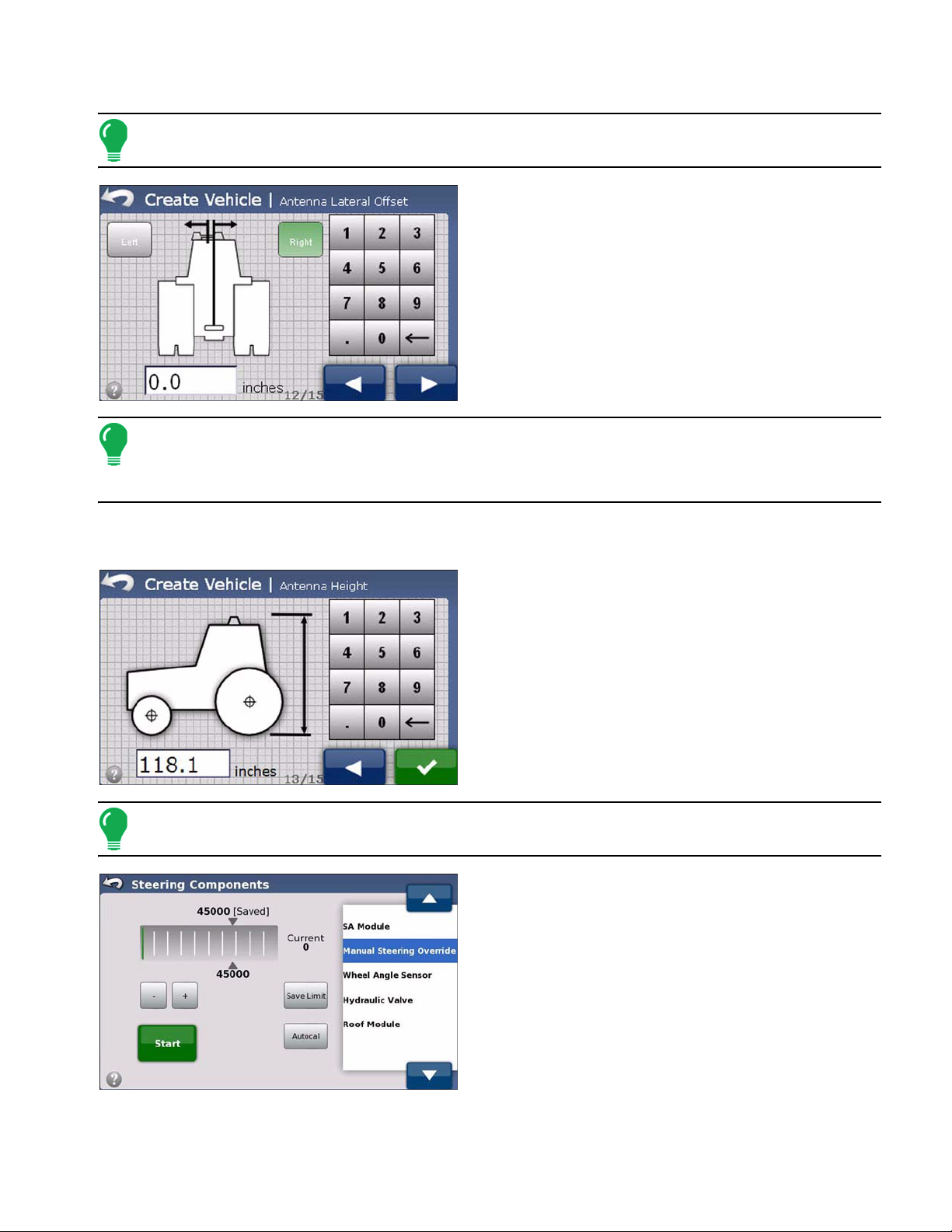
USING THE VEHICLE MENU
ACCESSING THE VEHICLE MENU
To access the Vehicle menu:
12 Ag Leader Integra and Versa Firmware Version 4.3 / Edge Firmware Version 5.1
1. Start the display.
Note: Before using your ParaDyme system with the OnTrac2 option, turn on the MDU2 power switch
prior to operating your vehicle.
2. Access the ParaDyme application. (See your display’s User Manual for details.)
3. Press the Vehicle button from the AutoSteer Setup screen.
4. Select the desired vehicle configuration procedure
button:
• Setup Wizard
Enables you to create and calibrate a new vehicle.
• Manage Vehicle
Enables you to oversee and modify the information relative
to the selected vehicle.
• Auto Calibrate
Starts a series of calibration steps that are critical to
achieve optimal autosteering.
• Steering Adjust
Enables you to change the way your vehicle steering performs.
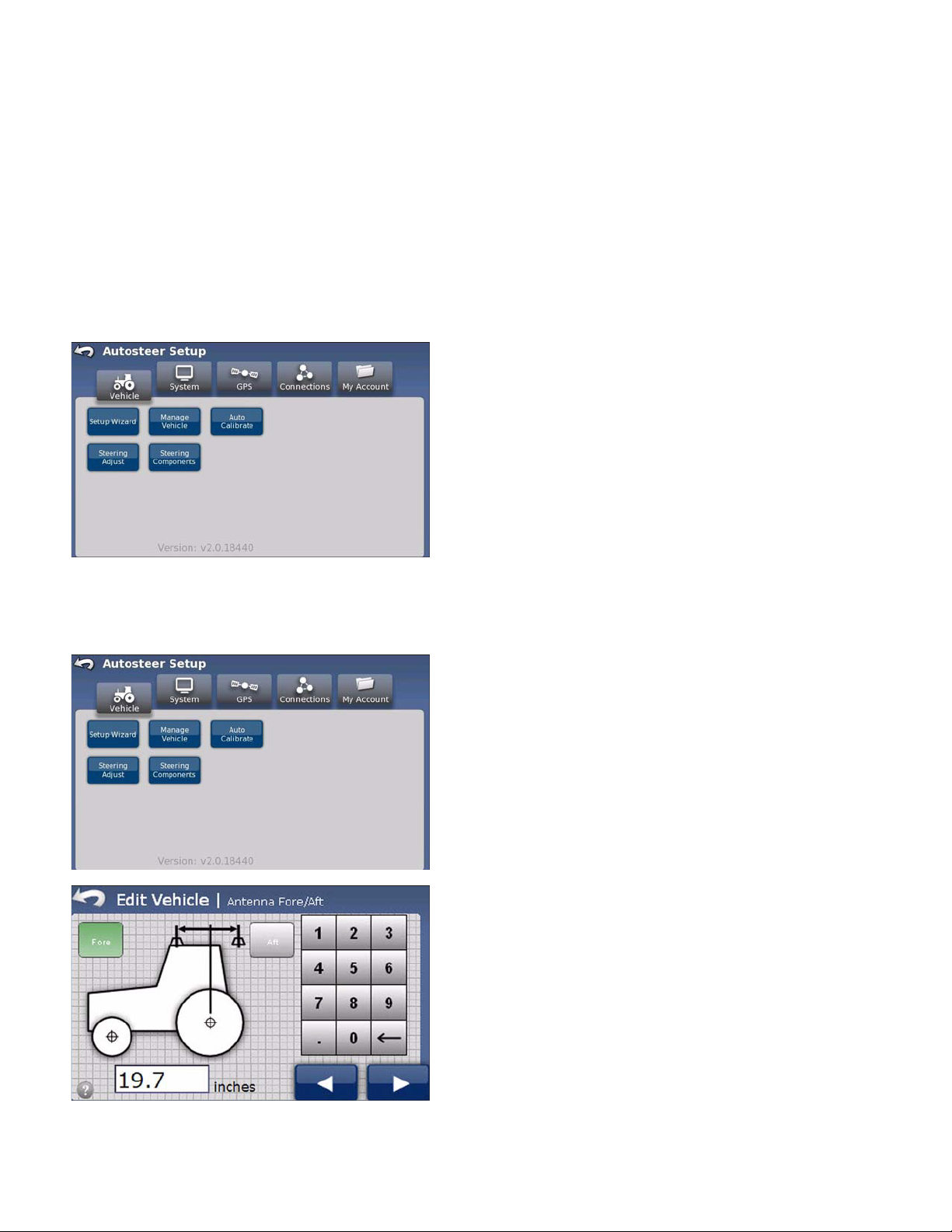
• Steering Components
Enable you to adjust various parameters of steering components, such as the manual steering override
kickout limit, and view diagnostic information for system components.
SETUP WIZARD
The Setup Wizard is used to create, calibrate and tune your vehicles with the Paradyme system and
ensures that all required steps are performed. To achieve the best possible steering accuracy with the
ParaDyme system you must create a vehicle, calibrate and then tune the system for your specific
vehicle.
Note: Active Vehicle means the vehicle being used for autosteering operations.
Initial Create Vehicle Procedure (First Time Use)
The initial (first ever) setup wizard leads you through a series of parameter settings before you access the standard vehicle setup screens. Once the initial vehicle has been setup, pressing the Setup Wizard button brings you directly to the standard vehicle setup screens. (See the
Procedure” on page 14
Note: The Initial Create Vehicle Procedure is also used after a database reset.
.)
“Standard Create Vehicle
To create the first vehicle for the first time use of the system:
13
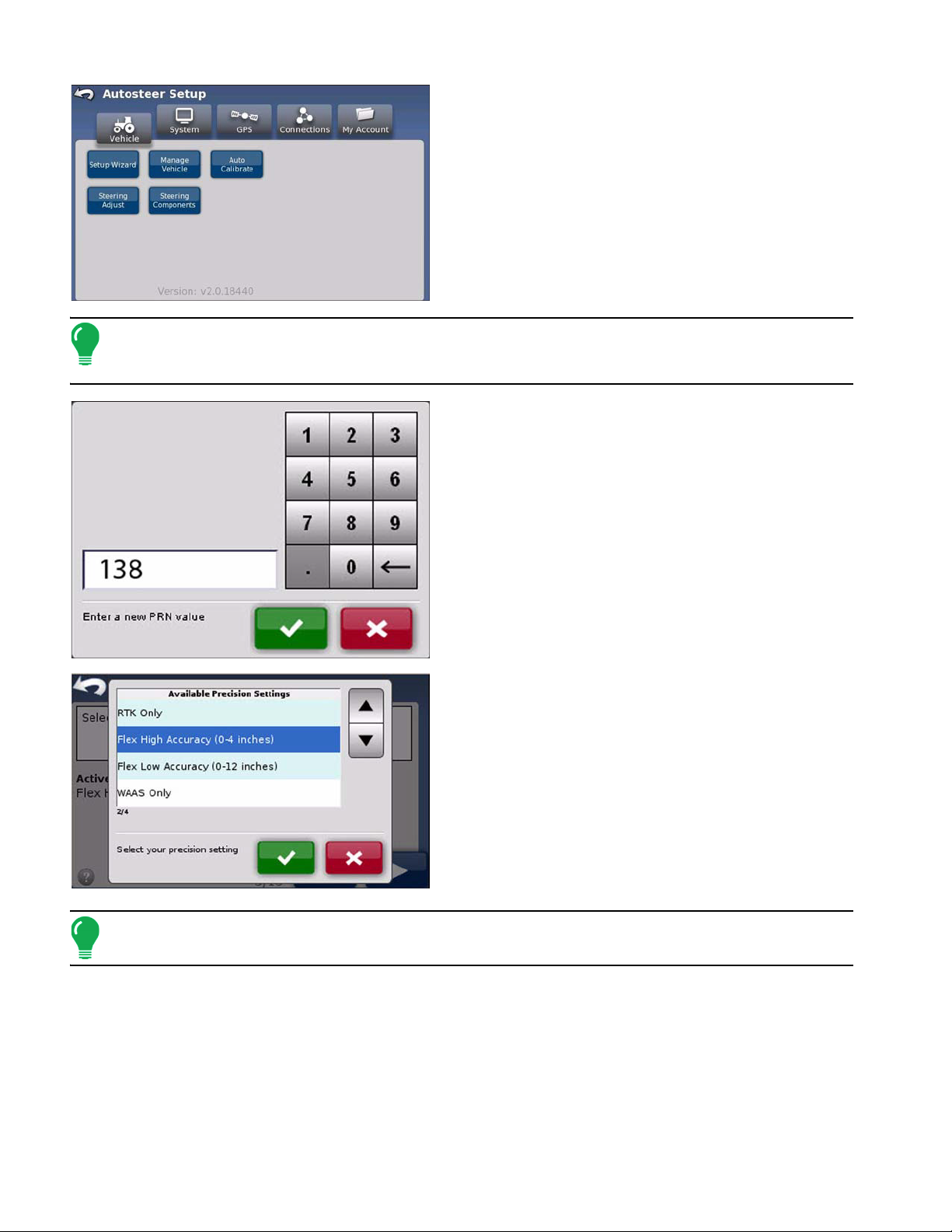
1. Press the Setup Wizard button. the GPS Setup
screen appears.
2. Press the Change Primary button. The Enter PRN
screen appears.
Note: PRNs are satellite identifiers. Enter the primary satellite PRN to use for WAAS correction. For
the US WAAS, try PRN 133 first, then PRN 138. If the signal is weak, consult the FAA web site, or
contact your dealer for updates.
3. Use the keypad to type a PRN number and press
the check mark button.
4. Depending on the optional radio hardware installed
on your system, the wizard guides you through the
necessary configuration steps. When finished, the
Precision Settings Info screen appears.
5. Press the Change Mode button. The Available
Precision Settings screen appears.
6. Select a precision setting and press the check mark
button to automatically move on to the Standard Create
Vehicle Procedure. There are five precision settings
available:
• RTK Only
• Flex High Accuracy (0 - 4 inches)
• Flex Low Accuracy (0 - 12 inches)
• OmniSTAR Only
• WAAS Only
Note: See the Precision Settings section of “Using the GPS Menu” on page 37 for details about
precision settings.
Standard Create Vehicle Procedure
Once the initial vehicle has been setup, pressing the Setup Wizard button brings you directly to the
standard vehicle setup screens.
14 Ag Leader Integra and Versa Firmware Version 4.3 / Edge Firmware Version 5.1
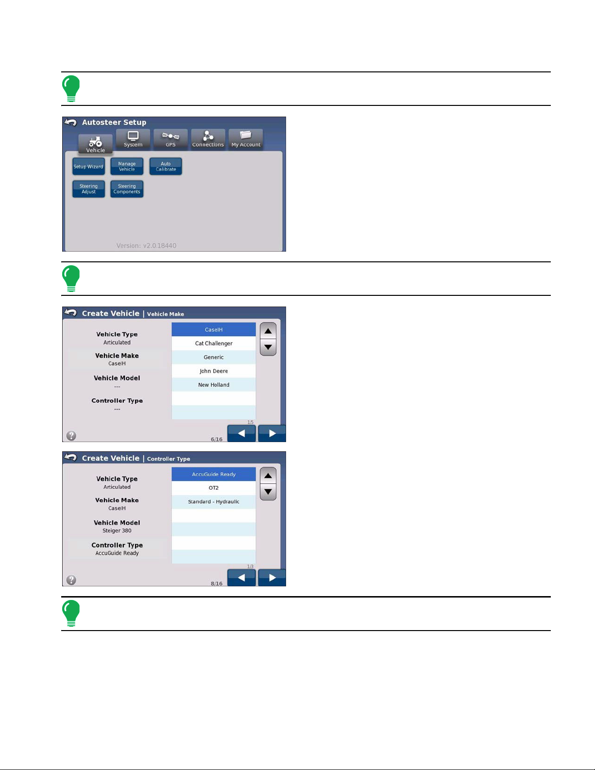
To create a vehicle after first time use of the system:
Note: The following procedure uses a common vehicle type, but the actual steps and images
displayed on your screen will vary according to the type of vehicle you selected.
1. From the Vehicle menu, press the Setup Wizard
button. The Vehicle Type list appears.
2. Using the up and down arrows, select the
appropriate vehicle type and press the Right Arrow
button. The Vehicle Make list appears.
Note: The list of vehicle types available on your system may not match those shown here. If your
vehicle is not on the list, pick the vehicle closest to your vehicle type or choose the generic option.
3. Use the up and down arrows to select your vehicle
make and press the Right Arrow button. The Vehicle
Model list appears.
4. Use the up and down arrows to select your vehicle
model and press the Right Arrow button. The Vehicle
Controller Type list appears.
5. Use the up and down arrows to select your vehicle
controller type and press the Right Arrow button. The
Vehicle Name screen appears.
Note: OT2 is an acronym for the OnTrac2 control system. If you are using an OnTrac2 controller the
screens and options will be slightly different.
15
6. Enter a name for the vehicle and then press the
Right Arrow button. The Wheel Angle Sensor dialog
box appears.
7. Press the appropriate button. The Wheel Angle
Sensor screen appears.
Note: The Wheel Angle Sensor is optional equipment that may not be required on your vehicle.
Note: If the Wheel Angle Sensor option is changed after AutoCal is completed, the AutoCal must be
redone.
8. Enter the Wheel Base value using the numeric
keypad. Press the Right Arrow button. The Antenna
Fore/Aft screen appears.
Note: The choice of units of measurement is made in the display’s Console Setup General Tab.
9. Enter the Antenna Fore/Aft value using the numeric
keypad, and then press the Fore or the Aft button as
applicable to your installation. When finished, press the
Right Arrow button. The Antenna Lateral Offset screen
appears.
• Fore indicates the antenna is located in front of the
vehicle’s control point.
• Aft indicates the antenna is located behind the vehicle’s
control point.
• The Control Point of a vehicle is defined as:
- Standard Wheeled Vehicle - Rear Axle
- Track Vehicle - Center of tracks
- Articulated Tractor - Pivot point of vehicle
16 Ag Leader Integra and Versa Firmware Version 4.3 / Edge Firmware Version 5.1
- Combine/Swather - Front Axle
Note: Be sure to select the appropriate offset for your configuration by pressing the Fore or Aft
button.
10. Enter the Antenna Lateral Offset value using the
numeric keypad and then select the Left Arrow or Right
Arrow button as applicable to your installation. When
finished, press the Right Arrow button. The Antenna
Height screen appears.
Note: The Antenna Lateral Offset value is tested and adjusted (if necessary) after vehicle creation
and calibration is complete. See
“Adjust Lateral Offset” on page 23. The Left Arrow and Right Arrow
buttons define the antenna position (center of the Roof Module) relative to the vehicle’s center line
when viewed from the rear.
Be sure to select the appropriate offset for your configuration by pressing the Left Arrow or Right Arrow
button.
11. Enter the Antenna Height value using the numeric
keypad and then press the check mark button. The
Manual Steering Override screen appears.
Note: Antenna height is measured from the antenna ground plane bottom to the ground surface.
12. You are now in the Manual Steering Override
kickout limit setting procedure. See
Override (Autosteering Kick-out Limit Adjustment)” on
page 26
for details about the procedure.
“Manual Steering
13. When the Manual Steering Override calibration is
complete, the Setup Wizard starts the Auto Calibrate
procedure. See
“Auto Calibrate” on page 20.
17
MANAGE VEHICLE
The Manage Vehicle screen enables you to manage and edit vehicles and vehicle settings. The Manage
Vehicle screen has three options:
• The
Select
• The
Edit
• The
Delete
Select the Active Vehicle
The Select button enables you to select the vehicle you will be using for your autosteering operations.
To select the active vehicle:
button enables you to select the vehicle you will be using for your autosteering operations.
button enables you to make changes to the vehicle parameters you select from the scrolling list.
button enables you to delete the vehicle you select from the scrolling list.
1. Press the Manage Vehicle button. The Manage
Vehicle screen appears.
2. Using the Up and Down arrows from the scrolling list,
select the vehicle you want to use for your autosteer
operations and press the Select button.
3. The active vehicle confirmation dialog box appears.
Press the check mark button and then press the Home
icon to get back to the AutoSteer Setup menu.
Edit Vehicle
The Edit button enables you to make changes to the parameters of the vehicle you select from the
scrolling list. To edit a vehicle:
1. Press the Manage Vehicle button. The Manage
Vehicle screen appears.
2. Using the up and down arrows, select the vehicle
from the list and press the Edit button. The Wheel Base
screen appears.
3. Enter the Wheel Base value using the numeric
keypad, and then press the Right Arrow button. The
Antenna Fore/Aft screen appears.
4. Enter the Antenna Fore/Aft value using the numeric
keypad and then press the Fore or the Aft button as
applicable to your installation, and then press the Right
Arrow button. The Antenna Lateral Offset screen
appears.
18 Ag Leader Integra and Versa Firmware Version 4.3 / Edge Firmware Version 5.1
Loading...