

Page 1
L160 Installation & Operations Guide
1 2005946 revC
Page 2

ABOUT THE L160
The L160 is a user-friendly lightbar with 16 tracking LED lights that indicate the vehicle’s position
in relation to the guidance line. The four LEDs in the middle of the lightbar are green and
indicate an “on-line” status. As the vehicle moves off-line to the right or left, yellow LEDs
illuminate and indicate the direction off-line. The Liquid Crystal Display (LCD) gives the operator
the current distance right or left from the guidance line as well as the current pass number and
degree heading. A RAM mount with a suction cup base offers unlimited mounting options. A
single cable connection provides a clean installation without cluttering the operator’s view.
LCD SCREEN
The L160 features a 50mm X 25mm LCD screen.
Do not use any harsh chemicals to clean the L160, as these could discolor or damage the graphic
overlay and LCD screen.
An anti-static wipe made for computer screens or a damp cloth is the correct way to clean the
screen and the L160 enclosure.
CAN-BUS TECHNOLOGY
The L160 is connected to, and powered by the display, which uses Controller Area Network (CAN)
technology.
Note: The L160 does not have its own power source, but is powered through the display.
EQUIPMENT SPECIFICATIONS
• Storage Temperature: -30°C to +70°C
• Operating Temperature: -10°C to +65°C
• Operating Input Voltage: 9 –16 V DC
• Peak Current Draw: 300 mA (5 Watts)
• Humidity - 100% condensing
• IP Rating ID - IP54
CAUTION: Exceeding these specifications may result in degraded operation and/or damage to the display.
CAUTION: The L160 is not to be used in a manner other than intended or described in this manual.
2
Page 3

MOUNTING THE LIGHTBAR
The L160 lightbar attaches to a flat surface in the cab of your vehicle. It is not intended to be
mounted outside of the cab.
1. Using the supplied screws (M5x0.8) , attach the RAM mount to the back of the L160 lightbar.
2. Select a clean, flat surface. If necessary, clean this surface with a damp cloth.
3. Securely attach the suction cup to this surface by turning the loc
lock position. A slight tug will confirm the suction cup is securely attached.
4. Adjust the L160 lightbar into a position that is viewable from the operator seat. Secure it in
position b
y tightening the RAM mount.
king collar clockwise to the
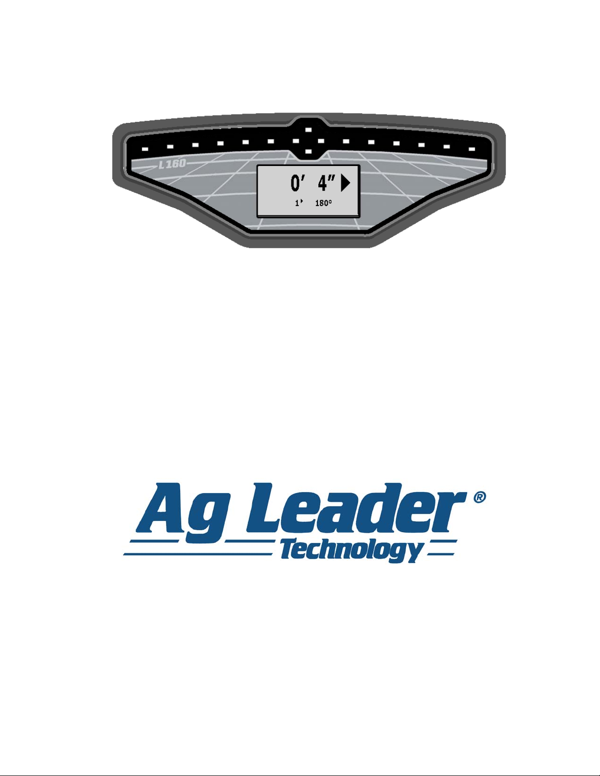
LCD SCREEN DURING RUN TIME
Once you have created the pattern in the
display, the LCD screen will show a set of
numbers and arrows. The information on this
screen includes the cross-track error, direction
toward the current guidance line, pass number,
direction from the original AB line, and degree
heading. The cross-track error is shown in feet
and inches for operators using Imperial units,
and centimeters for those using metric units.
LCD Screen (Shown for Imperial Units)
3 2005946 revC
Page 4

FUSE IDENTIFICATION AND REPLACEMENT
I
NFORMATION
CAUTION: The fuse is to be placed in the fuseholder in-line with the battery power cable and used with
display only.
4
Page 5

LED OPERATIONS
The LEDs on the L160 are representative of specific increments away from the current guidance
pattern. These increments are based on measurements that you specified in the setup. For
example, if you specify that the increments for the LEDs should be 12”, if two yellow LEDs appear
on your lightbar your vehicle is between 6” and 18” off track.
The lightbar has four green LEDs in the center, and six yellow LEDs on each side of the center.
• The four green LEDs show that your vehicle is on-line. Only three will show if your vehicle is
slightly off-track to the left or right.
• The yellow LEDs show that your vehicle is off track, according to previously-specified
increments.
Vehicle On-Line
Vehicle Off-Track
STATUS ITEMS
During the lightbar’s operation, you may see various status items appear on the LCD screen. The
table below describes these items.
Status Item Name Description
System Ready to
Define Pattern
Recording Pattern The display system is currently creating the guidance
No Communication The lightbar is unable to communicate with the
The lightbar is ready for you to set the A and B points
in your display (if required) in order to define the
guidance pattern. This item appears when no active
guidance pattern has been set.
pattern.
display.
No GPS The display system is not currently receiving a GPS
signal.
5 2005946 revC
Page 6

RELATED DOCUMENTATION
Consult your display manual's GPS/Guidance section for information related to creating patterns,
saving and loading, and general guidance functions.
PRODUCT REGISTRATION
When registering your Ag Leader Technology products by one of the following methods, you can
elect to receive notice of any new product updates or features.
Register by mail: Ag Leader Technology
2202 South Riverside Dr.
Ames, IA 50010
Register by Fax: 515-232-3595
Register at the Ag Leader Web site at http://www.agleader.com
COMPANY WARRANTY STATEMENT
Warranty
Ag Leader Technology will repair or replace at no charge any component of the L160 that fails
during normal service, while being used in an approved application, within two years of the
warranty start date. Warranty is not provided for damage resulting from abuse, neglect,
accidents, vandalism, acts of nature, or any causes that are outside of the normal intended use of
the L160. Ag Leader Technology shall not be liable for indirect, incidental, or consequential
damages to the dealer, end user, or third parties arising from the sale, installation, or use of any
Ag Leader Technology product.
Copyright Notice
Ag Leader Technology has copyrighted (© 2009) the contents of this manual. No reproductions
may be made without first obtaining the consent of Ag Leader Technology.
Service and Support
If you have additional questions or feel that you may be having a problem with your system, call
your local Ag Leader Technology dealer or call us directly at the phone number below. If we
determine you have a hardware failure, we will ship replacement hardware immediately.
Our Technical Support Department can be reached by phone at 515-232-5363, extension #1; or
through email at support@agleader.com.
6
 Loading...