

Page 1
CAN/GPS Simulator Operation Guide
Once the software and drivers are installed on the computer and the CAN/GPS simulator
connections are made, this guide will outline how to use the CAN/GPS simulator for various
operations.
DirectCommand Liquid
1. Follow the DirectCommand Quick Reference sheets to setup the display: Knowledgebase
> Product Manuals > Displays > Ag Leader® Integra/Versa Quick Reference Guides
2. Import field boundaries into the display by navigating to: Setup > Grower/Field
Management > Add a new field and then press the import button to bring in a boundary.
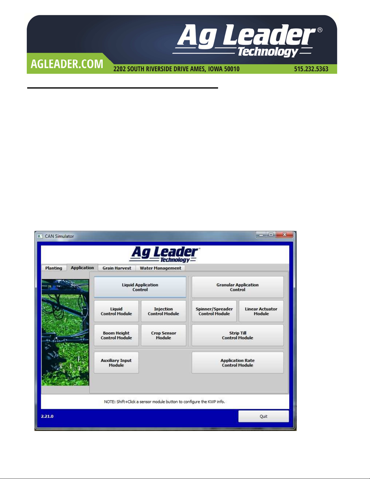
3. Open the CAN simulator program:
a. On the Application tab, click on Liquid Application Control. This will open the Auxiliary
Input Module and the Liquid Module required to load the run screen for a DirectCommand
liquid configuration.
PN: 2006008 Rev. A June 2014 Page 1 of 7
Page 2
DirectCommand Liquid Operation continued.
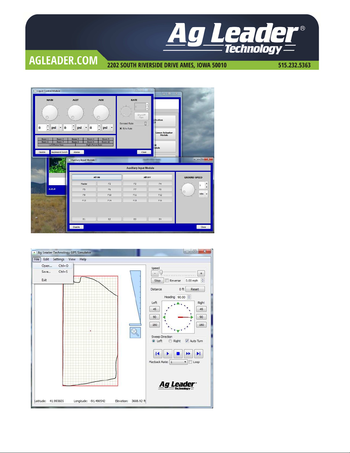
b. Click “All On” on the Auxiliary Input Module.
c. Open the GPS simulator program and click File > Open to browse for the field boundary
you loaded into the display. Assign a speed.
PN: 2006008 Rev. A June 2014 Page 2 of 7
Page 3

DirectCommand Liquid Operation continued.
d. On the map screen, assign a target rate in the product application tab. The display should
now be logging product application.
PN: 2006008 Rev. A June 2014 Page 3 of 7
Page 4

Harvest Operation
1. Follow the Harvest Quick Reference sheet to setup the display: Knowledgebase > Product
Manuals > Displays > Ag Leader® Integra/Versa Quick Reference Guides
2. Import field boundaries into the display by navigating to: Setup > Grower/Field
Management > Add a new field and then press the import button to bring in a boundary.
3. Open the CAN simulator program:
a. On the grain harvest tab, select Grain Yield Monitoring
b. Selecting grain yield monitoring will open all 3 harvest modules at once. On the speed
module, set the elevator speed in the range of 250-650 RPMs for the simulator to log. Also,
assign a value for grain flow on the grain sensor module.
PN: 2006008 Rev. A June 2014 Page 4 of 7
Page 5

Harvest Operation continued.
c. Open the GPS simulator program and click File > Open to browse for the field boundary
you loaded into the display. Assign a speed.
PN: 2006008 Rev. A June 2014 Page 5 of 7
Page 6

Troubleshooting
Problem: No Rate
Solution: 1. Make sure “Echo flow rate” is checked in the CAN simulator
2. Check that the modules are communicating with the display
a. Press the system diagnostics button
b. Choose the “CAN A” tab
i. You should have “232 DC Liquid” and “233 Aux Device” for a
liquid configuration
ii. You should have “232 DC Spreader” and 233 Aux Device” for a
granular configuration
iii. You should have “239 Speed Module”, “240 Flow Sensor” and
“244 Moisture Module” for a harvest configuration
c. Reboot display, simulator and/or computer
Problem: No DGPS
Solution: 1. Check which serial (communication) port you are connected to:
a. Go to the start menu of Windows and choose control panel
b. Choose system, then hardware
c. Select device manager
d. Expand ports (COM & LPT)
e. This will tell you which port to use:
f. Set the port under Settings> Serial Port” in the GPS simulator program
PN: 2006008 Rev. A June 2014 Page 6 of 7
Page 7

Troubleshooting continued.
Problem: MSVCP110.dll system error message:
Solution: 1. This error message pertains to a missing component of the Microsoft C++ distribution
package. The missing part can be found here.
2. Install the component then re-install the CAN simulator.
Problem: No CAN communication with the display
Solution: 1. Ensure the proper connections on the CAN simulator are made
2. Cycle power on the display to restore CAN communication
3. Restart the CAN simulator program and reopen the modules
PN: 2006008 Rev. A June 2014 Page 7 of 7
 Loading...