


0.00 ac
Operator Full
Event: 2013-12-16_14:51:15Dave
Grower: Grower1
Farm: Farm1
Products
Corn1
Corn2
A
Field: Field1
Productivity
E
Display Quick Reference
Guide
Operator Selection
A
0.0 mph
JD 8130, 24 Row Planter Planter
B
D
C
7.5 ac
Region:
7.5
7.5
<1>
Operating Conguration
B
JD 8130, 24 Row Planter
12:16:17 PM
11/23/2011
Equipment
Vehicle JD8130
Implement 24 Row Planter
Operator Selection
Select Operator
Operator Full
Options
Show Operator Selection on Startup
Note: If the active operator has a password,
the operator selection will always be displayed
on startup.
Operating Conguration
Name
Log Out
Management Selection
D
Management Selection
Growing Season
2013 Crop
Grower
Grower 1
Farm
Farm 1
Field
Field 1
Enable Management
Event Selection
New Event
2013-12-16_15:31:42
Corn
Conguration Setup
C
Vehicle
JD 8130
Vehicle
Offsets
Speed
Input
Auxiliary
Input
Equipment
Settings
Product Selection
E
Product Selection
Coverage
Coverage
Conguration Setup
1
Implement: 24 Row Planter
Full Swath:
Rows:
Sections:
Row
Shutoff
Offsets
Corn1
Corn2
Controller: None
60
24
2
Quick Reference Guide
2005979-ENG Rev F / AF:602-0300-01-E
1
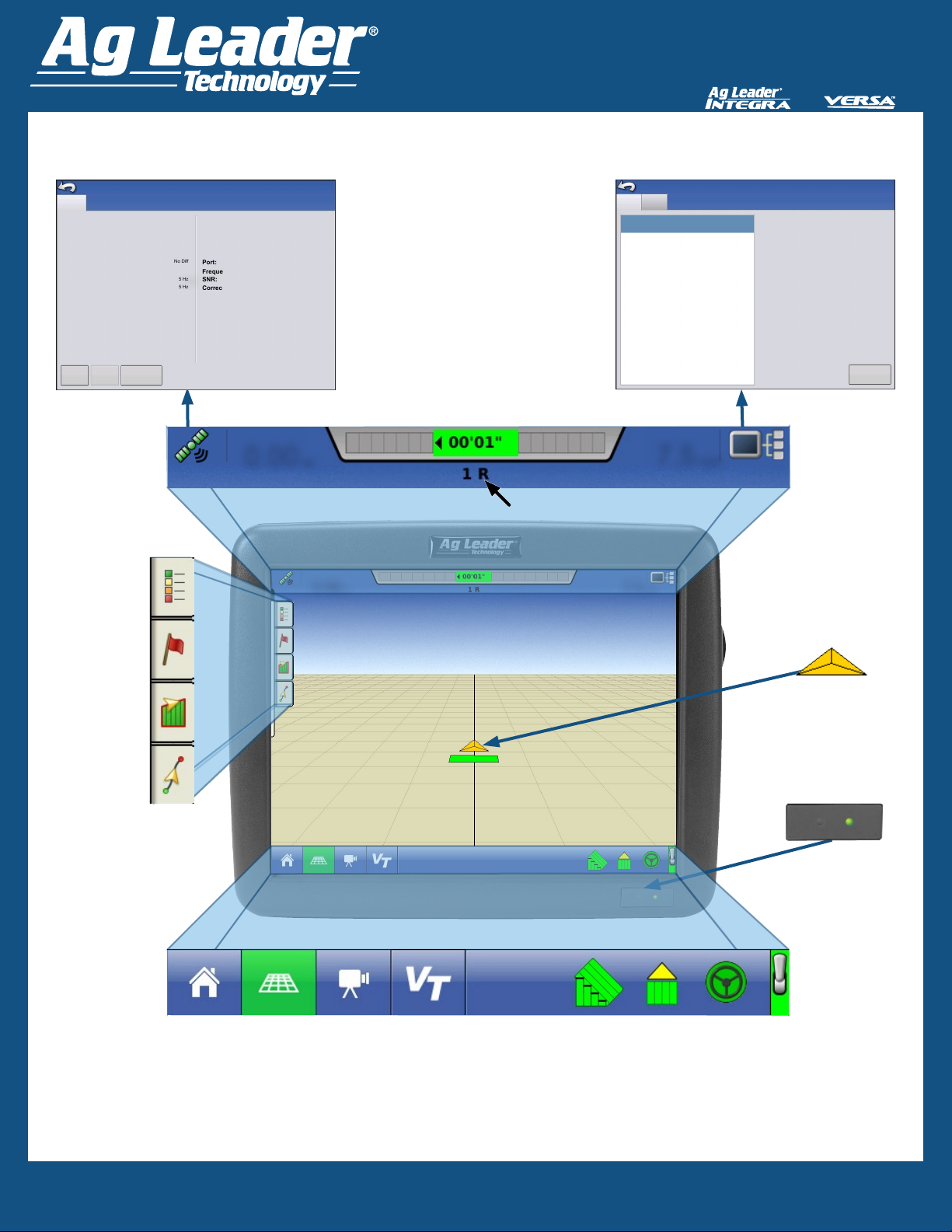
Display Quick Reference
Guide
Map Screen Layout
General
Latitude (N)
Longitude (E)
Elevation
Heading:
Number of Satellites:
Differential:
GPS Speed:
Position Rate:
Speed/Heading Rate:
View
Satellite
0 ‘ “
Plot Messages
GPS
Information
GPS Information
42.018898576
UTC Time:
-93.644081288
UTC Date:
1117.620
HDOP:
270.00000
VDOP:
7
PDOP:
No Diff
Port:
5 km/h
Frequency:
5 Hz
SNR:
5 Hz
Correction Age:
NMEA, 115200, 8 N 1
Area
0.00 ac
20:36:57
CAN A
CAN B
N/A
1.0
1.0
1.0
N/A
N/A
N/A
DISPLAY
Devices
Firmware:
Firmware ID:
Hardware ID:
Serial Number:
Revision:
Run Time:
Boot Counter:
3.0.24 / 3.0.21
VERSA
4002439
2011130060
2.5.0.0
63:42:47
44
Diagnostics
Device
On-Screen Lightbar
Speed
Information
7.5 mph
Guidance Pass Number
7.5 mph0.00 ac
Map Legend
Map Markers
Boundary
Guidance
Home Screen
Map Screen
Video Screen
Virtual Terminal
AutoSwath
Area Logging
Vehicle
Icon
Power
Indicator
Master Switch
Steering Status
Quick Reference Guide
2005979-ENG Rev F / AF:602-0300-01-E
2

Display Quick Reference
Guide
Status Bar Icons
Devices button - shows display information and diagnostics.
GPS Button - access diagnostic information about the GPS signal
Green - receiving corrected GPS signal
Yellow - receiving GPS signal only
Gray - no GPS signal
Flex Mode
Green - On Yellow - Exceeded
Task Bar Buttons
Home - returns to the home screen
Map View
Zoom to Extent - vehicle Icon is shown by an arrow inside a circle
Zoom to Detail - vehicle appears as a gold-colored triangle icon; changes to indicate data
being logged in the eld.
Perspective View - only available when guidance is active
Norac Engage Buttons
On Off
Function Buttons
On
AutoSwath
On Off
Off
Video Screen Button takes you to the video screen
Master SwitchArea Logging Status
On
Off
Steering Status
Engage - ON
Engage - Ready
Engage - Not Ready
Setup Buttons
Setup (on Home screen) - use to access the following features:
Conguration - create and adjust settings of vehicle, implement, controller, and product
Management - create and edit grower, farm, eld operator and season
GPS - enter and adjust guidance, GPS settings, and lightbar settings
Console - adjust time, date, brightness, volume, operating units, language; enable video
and virtual terminal; view features, and create and restore backups
Quick Reference Guide
2005979-ENG Rev F / AF:602-0300-01-E
3

Display Quick Reference
Guide
Connecting the Systems
Display System
Mounting
Brackets
Fuse Type
Blade Style (ATO/ATC)
5 A rating
15 A rating
Operating Voltage
9-16 V DC
Max Current Rating
Ag Leader Integra 4.0 A
Versa 2.5 A
ParaDyme/GeoSteer 10 A
OnTrac3 SystemDisplay System
Display System Display System
ParaDyme System
(Roof Module = IP65)
GeoSteer System
(GCU = IP66)
Quick Reference Guide
2005979-ENG Rev F / AF:602-0300-01-E
4

Display Quick Reference
Guide
System Features
• Sunlight-readable Screen
• Rugged sealed enclosure
• Compatible with most NMEA GPS receivers
• DirectCommand and SeedCommand Product
Control using Industry-Standard CAN Bus
interface
• Adjustable volume control
• Perspective 3D View Map
• Report Preview
• Automatic Field Selection
• Automatic Module Firmware Upgrade
• Advanced GPS Diagnostics
• USB media slot
• 28-pin plug compatible with other Ag Leader
displays.
• RAM mount
System Uses
• Manual Guidance
• ParaDyme™, GeoSteer™ and OnTrac3
automated steering
• Planter DownForce Control
• Norac UC5
• Video Camera Inputs
• Mapping Tillage Operations
• Mapping and Logging Product Applications
• Mapping of all eld boundaries, sub-boundaries,
waterways and terraces
• Grain Yield Monitoring
• Variety Logging
• Granular and Liquid Fertilizer Application
• Liquid Spray System Control
• NH3 Application Control
• Application Control of Multiple Bin Spinner
Spreaders
Technical Specications
Do not exceed the specications below:
• Storage Temperature:
-4° to +176°F (-20° to +80°C)
• Operating Temperature:
14° to +156°F (-10° to +70°C)
• Operating Input Voltage: 9 –16 V DC
• Max Current Rating: 4.0 amp
• Environmental Protection Rating: IP64
• No Protective Grounding required
• Use 150V minimum insulation rating for external
circuits
Color Touch Screen
The display features a color touch screen display.
The touch screen allows easy and intuitive
navigation through the screens on the display
without the need for any external keypad or
mouse devices. Here are a few key things
to remember if you are new to using a touch
screen device:
• Do not use any sharp objects for running
the touch screen device, this could result in
damage to the display. Using the tip of a nger
is the recommended method of operating the
display touch screen.
• Do not use any harsh chemicals to clean the
touch screen. Using a damp soft cloth or an
anti-static wipe made specically for cleaning
computer displays is the correct way to clean
the screen and the enclosure.
• The touch screen requires only a gentle touch
of about half-second in duration to operate
correctly. A common mistake is to try to
navigate too quickly through the system using
rm taps instead of gentle presses.
USB Flash Drive
A USB Flash Drive can be used to save and
transfer data in and out of the display.
Quick Reference Guide
2005979-ENG Rev F / AF:602-0300-01-E
Attaching the Display
Mount the display to a secure support inside
the vehicle cab taking the following into
consideration:
• The display must be readily accessible to the
machine operator
• The display must not obstruct the operator’s
normal driving view nor interfere with existing
machine controls
5

Display Quick Reference
Guide
Safety Notice: Read these safety instructions and the User Manuals thoroughly, and follow the instructions.
Steering System refers to the OnTrac2/OnTrac2+/OnTrac3 GPS Assisted Steering System and/or the ParaDyme system and/or the
GeoSteer system.
• Only an operator who is fully authorized to drive the vehicle can use the Steering System.
• The operator must not exceed the safe speed limit for the terrain on which the vehicle is operating.
• The operator must always be aware of his actions when operating the Steering System.
• When installing the Steering System do not force the components as this can result in damage to the components.
• Always follow the instructions in the installation, operation, and maintenance manuals.
• Only trained personnel should install the Steering System.
• Always inventory the components delivered to ensure all the correct components are present. Never use replacement components.
Only use original components.
• If there are any questions regarding the safe operation of the Steering System or the instructions in the manuals, immediately contact
your authorized dealer or technical support.
• Always use the correct tools to install the Steering System.
• To prevent injury, use caution when installing the Steering System.
• Do not use or operate the Steering System in unsafe weather conditions.
• Do not use or operate the Steering System on unsafe terrain.
• Only an operator who is trained, experienced or authorized can use or operate the Steering System.
• Before using the Steering System, the operator must have sufcient knowledge of how to operate the systems in a safe manner.
• When installing the Steering System, all safety precautions must be clearly understood. If there are any loose, missing or damaged
parts they should not be used.
• Before using the Steering System, verify all functions are checked and controlled to ensure they are working correctly. When there is
any doubt, do not take any risks - always contact your authorized dealer or technical support.
• Before operating the Steering System, verify all functions of the Operator Presence Switch to ensure it functions correctly.
• Powering the Steering System ON or OFF must be done by following the correct prescribed procedures.
• If any vehicle or system function is abnormal, for example if excessive vibrations or noise occur, immediately stop the vehicle, power
OFF the Steering System and contact your authorized dealer or technical support.
• When maintaining or cleaning the Steering System, it must be completely powered OFF and are free of any electrical currents.
• The operator of the Steering System in conjunction must read and understand all safety instructions so they can react in case of an
emergency.
• The authorized dealer must always carry out maintenance or repairs on the Steering System.
• During repair or replacement of components on the Steering System, only original components must be used.
• Operator or maintenance personnel must always wear the correct personal protection equipment when working on the Steering
System.
• Maintenance personnel must always use the recommended cleaning materials and accessories when the Steering System is cleaned.
• Unsafe conditions or situations with the Steering System must be reported to your authorized dealer or technical support.
• Objects cannot be placed on or in the area of the Steering System.
• During installation, calibration, and tuning of the Steering System the vehicle wheels may turn to the left and right. Be sure all people
and obstacles are clear of the wheels before proceeding.
• Put the vehicle seat and steering wheel in the normal operating position and verify that the Mechanical Drive Unit (MDU) does not
interfere with any controls.
• The operator must read and acknowledge the Automatic Steering Liability Notice each time the system is powered ON.
• If there are any questions regarding the safe operation of the Steering System or the operating instructions, contact your authorized
dealer or technical support.
• The operator must keep alert for obstacles in the path of the vehicle. The Steering System cannot identify or avoid obstacles.
• The operator must remain in the operator’s chair in the vehicle while the Steering System is engaged.
• Only use the Steering System in an open eld. The systems must be powered OFF when the vehicle is on any type of roadway.
Liability Notice Novariant B.V. cannot be held responsible or liable in any way for any damages and / or accidents that occur through the
malfunction of the machine on which it is installed, malfunction of the machine components, machine attributes (e.g. trailers), third party
interference(s) or acts of the operator outside the intended use such as prescribed by Novariant B.V.
COPYRIGHT NOTICE Ag Leader Technology has copyrighted (©2014) the contents of this publication and the operating program for the
Ag Leader Integra and Versa systems. No reproductions may be made without rst obtaining the consent of Ag Leader Technology.
Quick Reference Guide
2005979-ENG Rev F / AF:602-0300-01-E
6
 Loading...