

Page 1

Tillage Quick Reference Guide
Section 1: Configuration Procedure
The following setup procedure describes how to configure Tillage equipment. To
begin this procedure, to the Configuration Tab in Tillage, press the Add button, and the
Operating Configuration Wizard appears. Follow the instructions below.
Tillage Configuration
STEPS ACTION
1
2
3
4
5
6
Select Vehicle
Use the drop down list to select the vehicle you would like to use in this
configuration and proceed to Step 5. If there are no vehicles in the list press the New
button. Press Next to continue.
Create New Vehicle
The Vehicle Setup Wizard appears. Select the correct Vehicle Type from the dropdown list. Press Next to continue.
Enter Vehicle Information
Use the keyboard buttons to enter the vehicle's make and model. Press Next to
continue.
Enter Vehicle Name
Use the keyboard buttons to enter the vehicle's make and model. Press Finish to
return to the Operating Configuration Wizard.
Select Implement
Use the drop down list to select the implement you would like to use in this
configuration and proceed to Step 10 on page 2. If there are no implements in the list
press the New button. Press Next to continue.
Select Implement Attachment Method
The Implement Setup Wizard appears. Use the drop down list to select an implement
attachment method. Press Next to continue.
7
8
Enter Full Swath Width
Use the numeric keypad to enter the full swath width of the implement. Press Next
to continue.
Enter Distance from Hitch to Application Point (front to back)
Enter the distance from the hitch to the application point using the numeric keypad.
Press Next to continue.
Part No. 2002831-31 Rev. B
1
Page 2

Tillage Configuration (continued)
STEPS ACTION
9
10
11
12
Enter Implement Name
Use the keyboard button to enter a name for the implement. Press Finish to return to
the Operating Configuration Wizard.
Select Implement Switch Polarity
If you will be using an implement switch, choose standard or reversed polarity. If an
implement switch is not in use, select None. Press Next to continue.
Note: Set to None if there is not an implement switch connected to shut off logging
when the implement is raised. This setting can be changed under Configuration
Settings.
Select Ground Speed Source
Select your ground speed source. If you will be using GPS as the primary you will
need to select a secondary source. Press Next to continue.
Edit Configuration Name
Use the keyboard button to edit the suggested configuration name. Press Finish to
complete the configuration process.
Part No. 2002831-31 Rev. B
2
Page 3
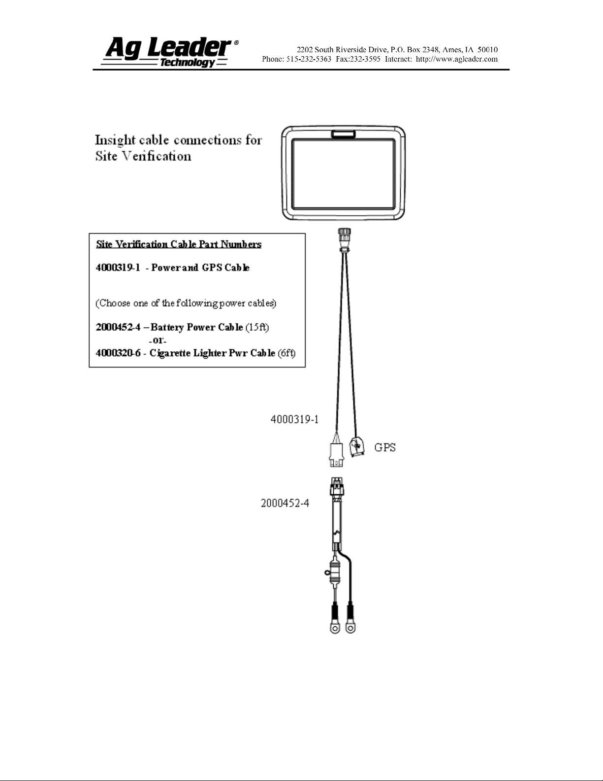
Section 2: Site Verification Setup
Part No. 2002831-31 Rev. B
3
Page 4

Section 3: Implement Switch Setup
Part No. 2002831-31 Rev. B
4
Page 5

Section 4: Setup Menu
Part No. 2002831-31 Rev. B
5
Page 6

Section 5: Run Screen Functionality
Part No. 2002831-31 Rev. B
6
Page 7

Section 6: Tillage AutoSwath™
The AutoSwath feature automatically increases or decreases the logged width of the
tillage equipment according to your field's boundaries and previously-tilled areas. By
doing so, the InSight display records a change in logging data, even though no
mechanical change has actually taken place. By recording changes to your logging data,
AutoSwath ensures the InSight display's correct area calculation, which also improves the
accuracy of your field summaries and reports.
AutoSwath™ Explained
As your vehicle travels beyond a
tilled area, the AutoSwath feature
automatically changes the active
width of the tillage equipment by the
use of a "stair-step" method, in
which the logged width is reduced by
successive amounts.
Select the AutoSwath Checkbox
To enable the AutoSwath feature,
select the AutoSwath checkbox,
located at the bottom left-hand side
of the Run screen, above the tabs.
The section width represented by the
indicator bar was automatically
configured for you when you created
the configuration on your implement.
At times, this section width may
change if you make adjustments to
the AutoSwath's sensitivity settings.
These sensitivity levels compensate
for varying degrees of GPS
performance.
Part No. 2002831-31 Rev. B
7
Page 8

Section 7: AutoSwath Sensitivity
Settings
The AutoSwath feature automatically increases or decreases the logged width of the
tillage equipment, according to your field's boundaries and previously-tilled areas. The
AutoSwath feature includes sensitivity levels, which compensate for varying degrees of
GPS performance. To change sensitivity levels, select the Configuration Tab, and press
the AutoSwath Settings button. These sensitivity settings are specific to that
combination of Vehicle and Implement.
If swath adjustments are performing inaccurately, adjust the sensitivity accordingly.
Sensitivity 3 is the default setting. Other settings include:
Setting Purpose
Sensitivity 5
Sensitivity 4
Sensitivity 3
Sensitivity 2
Sensitivity 1
Note: You must have an unlock code to activate the AutoSwath feature. If you have been
using AutoSwath with the DirectCommand™ system, the feature is already activated and ready to
use. If you have not unlocked the AutoSwath feature yet, the code can be purchased through your
local Ag Leader dealer.
Use with RTK or DGPS sub-meter, terrain-compensated GPS.
Use with RTK or DGPS sub-meter GPS. Terrain compensation
recommended.
Use with sub-meter accurate GPS.
Use with 1+ meter accurate GPS.
Swath segments are all on or all off. Use with 1+ meter accurate
GPS.
Part No. 2002831-31 Rev. B
8
 Loading...