

Page 1

Granular Strip-Till Control Module
Quick Reference Sheet
Section 1: Configuration Procedure
The following setup procedure describes how to configure a Strip Till Module for
a multiple product application. To begin this procedure, go to the Application Setup
Configuration Tab and press the Add button.
Note: In order for you to use this configuration at the Run screen, you must also
configure a vehicle, implement, controller and product(s). For more information on how
to configure these, consult the InSight User Manual.
Strip-Till Configuration (for multiple products)
STEPS ACTION
1
Select Equipment Configuration Type
The Operating Configuration Wizard appears. Select either Single Product Application, or
Multiple Product Application. As this particular procedure describes how to configure a
Multiple Product Application, we have chosen this setting.
Note: You must have purchased a Multi-Product unlock code from Ag Leader in order to use
the Multiple Product Configuration.
2
3
4
5
6
Select Vehicle
Use the drop-down menu to choose a vehicle, or press the New button to enter a new vehicle.
Press Next to continue.
Add Equipment for Multiple Product Configuration.
The Add Additional Application Equipment window appears. From here, you may add
additional equipment or controllers to your configuration. Add equipment by pressing the Add
button.
Note: If you choose to add additional equipment, add them in the same order as the implements
are attached.
Select Implement
Select an Implement from the drop-down list menu, or press the New button to create a new
implement. Press Next to continue.
Select Implement Attachment Method
Use the drop-down list to select an implement attachment method. Press Next to continue.
Enter Full Swath Width
Use the numeric keypad to enter the full swath width of the implement. Press Next to continue.
Part No. 2002831-42 Rev. C
1
Page 2

Strip-Till Configuration (for multiple products)
STEPS ACTION
7
8
9
10
11
12
13
Enter Number of Boom Sections
Use the up and down arrow keys to enter the number of sections of the implement. Press
Next to continue.
Enter Boom Section Widths from Left to Right
For implements with more than one boom section, the system will default to the appropriate
number of equal width boom sections. To edit any of the boom values, select the desired
section from the list and press the numeric keypad to enter in a new width. Press Next to
continue.
Enter Distance from Hitch to Application Point
Enter the distance from the hitch to the application point (from front to back) using the
numeric keypad. Press Next to continue.
Implement Setup Wizard
Press Next to continue.
Enter Implement Name
Use the keyboard button to enter a name for the implement. Press Finish
Select Operating Mode
Use the drop-down menu to select Rate Logging/Control; then press Next.
Select Controller
Press the New button to add a controller; then press Next
14
Select Controller Device and Device Type
Select DirectCommand from the Device drop-down list box. Scroll down on the Direct
Type list box and select Granular Strip-Till Control. Press Next to continue.
15
Select Controller Device and Device Type
Select DirectCommand from the Device drop-down list box. Scroll down on the Direct
Type list box and select Granular Strip-Till Control. Press Next to continue.
16
Enter Suggested Controller Name
A default name of DirectStripTill appears. Press Finish, or use the on-screen keyboard to
enter a new name, if desired
17
Select Controller Channel
Use the drop-down menu to select a controller channel, then press Next to continue.
18
Select Container
Use the drop-down menu to select a container, or press the New button to enter a new
container; then press Next to continue.
Part No. 2002831-42 Rev. C
2
Page 3

Strip-Till Configuration (for multiple products)
19
20
21
22
23
Enter Container Capacity and Units
The Container Setup Wizard appears. Use the numeric keypad to enter the container
capacity and the drop-down menu, located underneath, to enter units. Press Next to
continue.
Select Container Name and Location
Use the keypad to enter a Container Name, and the drop-down menu underneath to enter
a Container Location.
Enter a Suggested Configuration Name
Use the keypad to enter a different name for the configuration (if desired), and press
Next. A suggested name has been provided, based on your previous selections. If this
name does not fully describe the configuration, you may change it here.
Add Equipment for a Multiple Product Application
The Operating Configuration Wizard reappears. Because we specified that we were
configuring a multiple product application in the first step of this procedure, we are now
asked to add more equipment to our configuration. Repeat steps 3-21. When you have
repeated these steps and have come back to the Add Equipment window, press the Next
button; then press Finish.
Select Ground Speed Source
Select your ground speed source. If you will be using GPS as the primary you will need
to select a secondary source.
Note: The Ground Speed Sensor must be calibrated for accurate speed and area
calculations, under the Vehicle Tab. Press Next to continue.
24
Enter Suggested Configuration Name
Use the keypad to enter a suggested name for your configuration. A suggested name has
been provided, based on your previous selections. If this name does not fully describe the
configuration, you may change it here. Press Finish when complete.
Part No. 2002831-42 Rev. C
3
Page 4

Section 2: Strip Till Hardware Setup
Part No. 2002831-42 Rev. C
4
Page 5

Section 3: Setup Menu
Part No. 2002831-42 Rev. C
5
Page 6
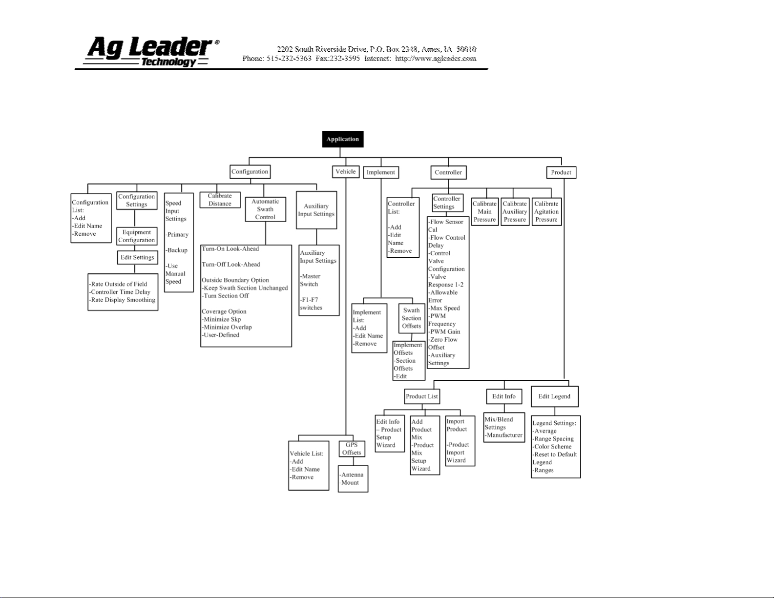
Section 3: Direct Command Menu Tree
Part No. 2002831-42 Rev. C
6
Page 7

Section 4: Run Screen Functionality
Part No. 2002831-42 Rev. C
7
Page 8
Section 5: Key Settings/Functionality
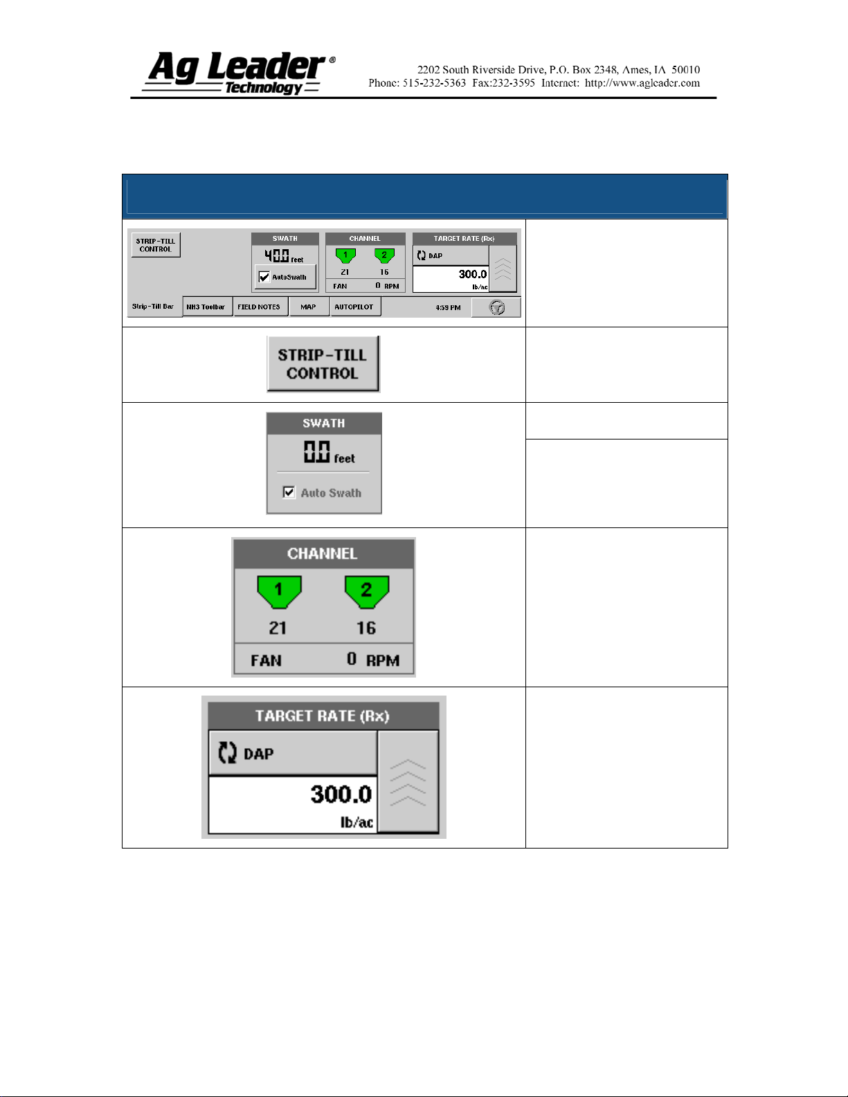
Strip Till Application Rate Control Tab
The Application Tab shown at
left is a typical configuration
for a Strip Till module.
Press to display the Strip Till
window and settings.
Displays active swath width.
The Auto Swath check box
allows the enable/disable of
the Automatic Swath Control
functionality.
Displays the status of the
product control channel. When
the fertilizer bin is grey no
product application is taking
place. When product is being
applied, the fertilizer bin icon
will turn green.
Displays the current target
application rate. Press the up
arrow button to go to the
Target Rate Application
window.
Part No. 2002831-42 Rev. C
8
Page 9

Strip Till Control Settings
Product Density:
This density value (shown in
pounds per cubic foot, or lb./ft.3),
is stored with each combination of
product and control channel. Use
the keypad to edit, if needed. Note:
For proper machine performance
and accuracy, you should check the
Product Density daily.
CFR 1:
This setting represents the volume
of product distributed on the field
with each revolution of the
metering circuit. This is shown in
Cubic Feet per Revolution
(ft.3/rev).
Caution: New products will have a
default CFR number the first time
they are used. You must either
manually enter or perform a CFR
calibration routine for each product
once that product is created,
otherwise misapplication will
occur.
Static CFR Calibration: Press the
Static CFR Calibration button to
perform an automated routine to
calibrate each metering circuit.
This calibration is performed
before applying in field conditions.
In-Field CFR Calibration: Press
the In-Field CFR Calibration
button to perform an automated
routine to adjust the calibration
number for the selected metering
circuit. This calibration is
performed if there is a difference
between the amount of product as
logged as compared to what was
actually applied.
Part No. 2002831-42 Rev. C
9
Page 10

Section 6: Strip Till Calibration
To perform the Static CFR Calibration, press the Static CFR Calibration button in the
Strip-Till Control Window.
Static CFR Calibration Procedure (Strip Till)
STEP
1
2
3 Enter Simulated Target Rate
4 Start Target Rate Countdown
5 Enter Actual Dispense Amount
ACTION
Read Static Calibration warning
A warning appears, advising to disable the blower fan circuit and prepare to catch any
product dispensed in an appropriate container. Press OK.
Select Metering Circuit to Calibrate
The CFR Calibration Wizard appears. Choose the desired channel to calibrate, and
press Next.
Enter Dispense Amount
Use the numeric keypad to enter the amount of product to be dispensed into the
container, and press Next.
Use the numeric keypad to enter a simulated target rate, shown in pounds per acres.
Press Next when finished.
Press the green Start button to begin the target rate countdown. As the countdown is
started, the button will turn red and state Stop. When the countdown is complete, press
the Next button.
Enter the actual dispense amount, in pounds.
Note: The CFR will be calculated from the actual product amount dispensed.
6 Calibration Complete
A message appears, stating that your calibration is complete, and showing the CFR
amount, in cubic feet per revolution.
Either:
Press the Repeat Calibration button, or
Press Finish.
Part No. 2002831-42 Rev. C
10
 Loading...