

Page 1

Granular Spinner Spreader Module
Quick Reference Sheet
Section 1: Configuration Procedure
The following procedure describes the complete process of configuring a granular
spinner bed control system. To begin, go to the Application Setup Configuration Tab,
press the Add button, and the Operating Configuration Wizard appears.
Note: In order for you to use this configuration at the Run screen, you must
configure a vehicle, implement, controller and product(s). For more information on how
to configure these, consult the InSight User Manual.
Granular Spinner Spreader Configuration
STEPS ACTION
1 Select Equipment Configuration Type
Note: This step will only be present if the Multi-product feature has been
unlocked in the display. Skip ahead to Step 2 if you have not purchased a
Multi-product unlock code.
Select Single Product Application from the drop-down list, then press Next
to continue.
2 Select Vehicle
Use the drop-down list to select an existing vehicle from the Vehicle list, or
press New to launch the Vehicle Wizard to create a new vehicle.
Note: If you do not need to create a new vehicle, skip ahead to Select
Operating Mode in Step 7 on page 2.
3 Create New Vehicle
If you pressed New, the Vehicle Setup Wizard appears.
Self-Propelled Spreader operators should select Self-Propelled
Spreader from the Vehicle Type list box. Select Spinner from the
Spreader Type list box; then press Next to continue.
Other operators should select another vehicle type under the Vehicle
Type list.
4 Enter Vehicle Information
Use the on-screen keyboard to enter names for the Vehicle Make and Model.
Press Next to continue.
Part No. 2002831-39 Rev. D
1
Page 2

Granular Spinner Spreader Configuration (continued)
STEPS ACTION
5 Enter Vehicle Name
The display combines the Vehicle Make and Model for use as a Vehicle
Name. Use the on-screen keyboard to edit the vehicle name if desired. Press
Finish to complete Vehicle setup and continue with the configuration process.
If you selected Self-Propelled Spreader in Step 3 on page 1, then skip
ahead to Step 7.
If you selected another type of vehicle, then continue below.
6 a Select New Implement
Select an implement from the drop-down list menu, or press the New button to
create a new implement.
6 b Select Implement Attachment Method
Use the drop-down list to select an implement attachment method. Check the
Spinner Spreader Implement Type check box; then press Next to continue.
6 c Enter Distance From Hitch to Application Point
Enter the distance from the hitch to the application point using the number pad
button. Press Next to continue.
6 d Enter Implement Name
Use the keyboard button to enter a name for the implement. Press Finish to
complete the implement setup process and return to the Operating Setup
Wizard.
7 Select Operating Mode
Select Rate Logging/Control from the drop-down list box as the operating
mode. Press Next to continue.
8 Select Controller
Use the drop-down menu to select a controller, or press the New button to add
a controller. Press Next to continue.
Note: If you do not need to create a new controller, skip ahead to Step 11 on
page 3.
Part No. 2002831-39 Rev. D
2
Page 3

Granular Spinner Spreader Configuration (continued)
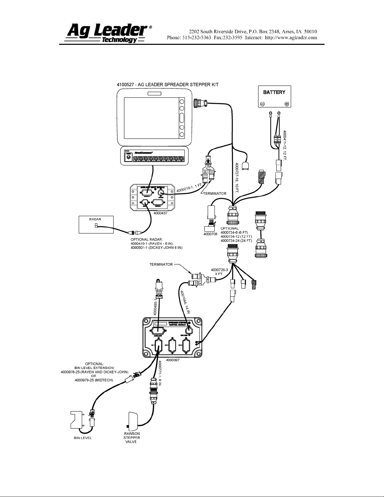
9 Select Controller (for Spinner Spreaders or Stepper Spreader Control)
If you chose to enter a new controller in Step 8, the Controller Setup Wizard
appears. Select DirectCommand from the Device drop-down list box.
Notes:
Choose the appropriate Direct Type according to the module’s part
number:
4000395 – Spinner Spreader Control 1 CH
4000396 – Spinner Spreader Control 3 CH
4001611 – Spinner Spreader Control 5 CH
4000397 – Spreader Stepper Control
Press Next to continue.
10 Enter Suggested Controller Name
The display assigns a default name of DirectSpreader to the controller. Use
the on-screen keyboard to edit the name if desired. Press Finish to continue
with the configuration process.
Note: If you selected Stepper Spreader Control in Step 9, then skip ahead to
Step 12.
11 Select a Controller Channel
The Select Control Channel window appears. Use the drop-down menu to
select a controller channel, then press Next.
12 Select Container
Press New to start the process of adding a product Container (BIN) to the
system.
Note: If you are using an existing container, and you do not need to enter a
Container Name, skip ahead to Step 15.
13 Enter Container Capacity and Units
Use the numeric keypad to enter a capacity, and the drop-down menu to enter
in the type of units. Press Next to continue.
Part No. 2002831-39 Rev. D
3
Page 4

Granular Spinner Spreader Configuration (continued)
14 Enter Container Name and Location
Use the keypad to enter a Container Name, and use the drop-down menu to
enter a Container Location. Press Finish and you will return to the Operating
Configuration Wizard.
15 Select Ground Speed Source
The Operating Configuration Wizard appears. Select Primary and Backup
speed inputs from the drop-down menus. Press Next to continue.
16 Enter Suggested Configuration Name
The display combines the Vehicle and Controller names used during the setup
process to use as the Configuration name. Use the on-screen keyboard to edit
name if desired. Press Finish to complete the setup wizard process.
17 Configuration Complete
Part No. 2002831-39 Rev. D
4
Page 5

Section 2: Standard Spreader Setup
Part No. 2002831-39 Rev. D
5
Page 6
Section 3: Standard Stepper Setup
Part No. 2002831-39 Rev. D
6
Page 7
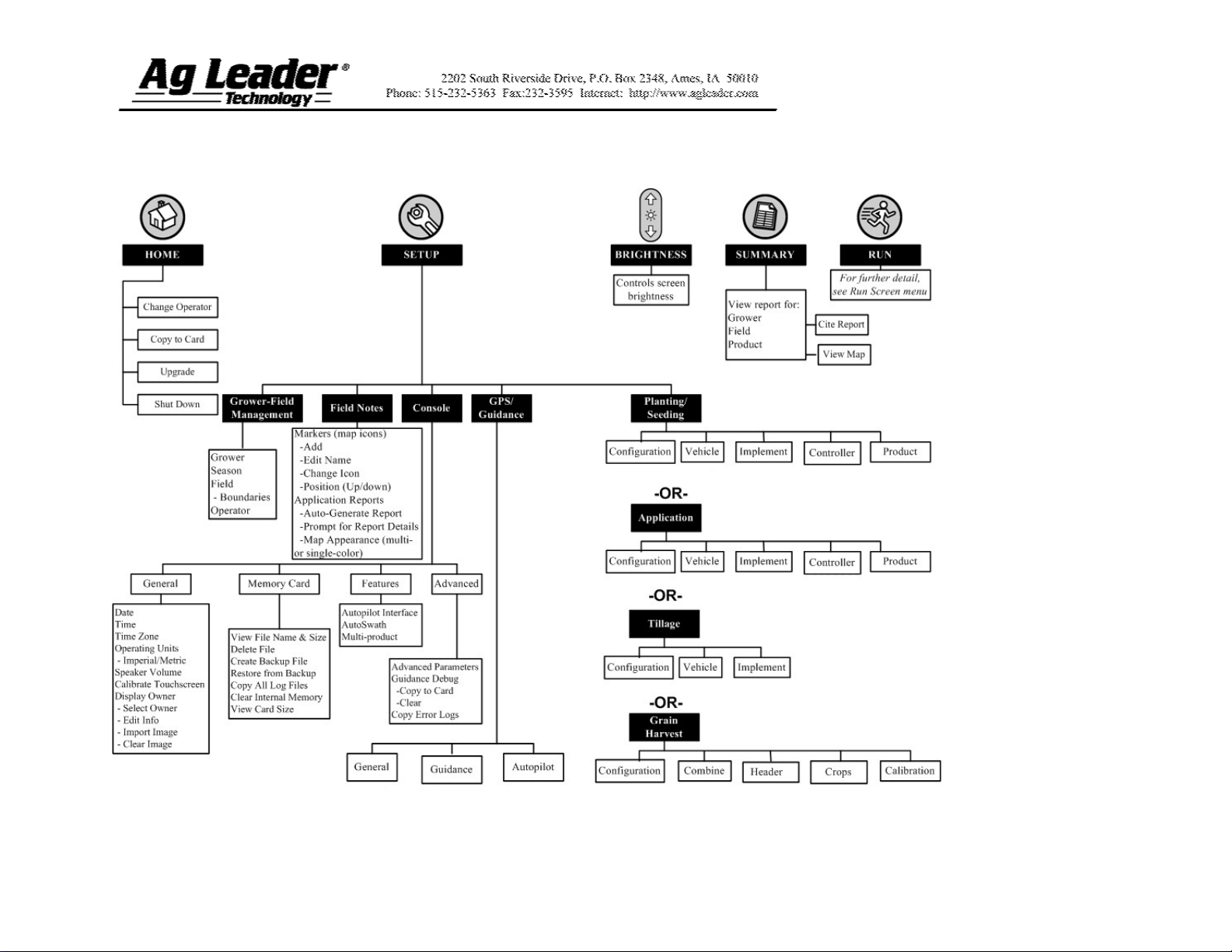
Section 4: Setup Menu
Part No. 2002831-39 Rev. D
7
Page 8
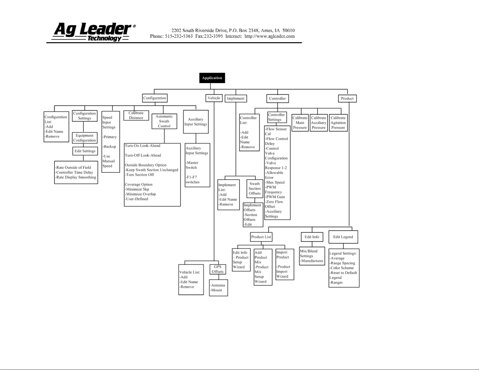
Section 5: Direct Command Menu Tree
Part No. 2002831-39 Rev. D
8
Page 9

Section 6: Run Screen Functionality
Part No. 2002831-39 Rev. D
9
Page 10
Section 7: Key Settings/Functionality
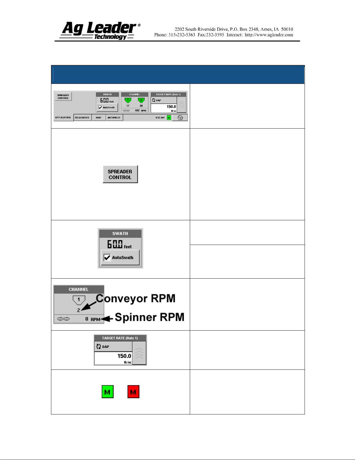
Spinner Spreader Application Rate Control Tab
The Application tab for spinner spreader
control has several buttons and status
display areas that are specific to granular
product control. This table outlines the
details of these controls.
Press to display the Spreader Control
window and settings. These settings
include:
Spread Width
Spinner Speed (if enabled)
Product Density
Feed Gate Opening
Conveyor Rate
For more information, see Section 6 “Run
Screen Functionality Menu”.
Displays active spread pattern width.
The Auto Swath check box allows the
enable/disable of the Automatic Swath
Control functionality. (Requires an unlock
purchase).
Displays the status of the product control
channel. When the fertilizer bin is grey as
shown at the left, no product application is
taking place. When product is being
applied, the fertilizer bin icon will turn
green.
Displays the current target application rate.
Press the up arrow button to go to the
Target Rate Application window.
The Master Switch Indicator shows if the
master switch is on (green) or off (red).
The master switch is shown in the F1
position on the Auxiliary Input Settings
window.
Part No. 2002831-39 Rev. D
10
Page 11
Section 8: Controller Settings
These settings are shown in Controller Settings window, accessed via the Controller
Settings button on the Controller Tab. These settings appear on the Channel Tab.
Controller Settings - Channel Tab
Setting
Name
Shaft Speed
Cal
Control Valve
Configuration
Response
Threshold
Valve
Response 1
Default
Setting Description/characteristics
180
Servo
15
40%
Calibration number representing the pulses that equal one revolution of
the rate control metering system.
Setting specifies the type of control valve being used for the rate control
functions of the controlling system.
Determines where the control channel switches between using Valve
Response 1 and Valve Response 2 speed setting. Leaving all other valve
control settings at the default value and making a small adjustment to this
setting is usually all that is required to fine-tune system performance.
Decreasing this value will have the overall effect of speeding up
servo valve response.
Increasing this value will have the overall effect of slowing servo
valve response.
Determines the speed of the servo valve when product control error
exceeds the Response Threshold setting. Valve Response 1 represents the
fast speed of the servo valve. Decreasing the value will cause the servo
valve to run slower.
Valve
Response 2
Allowable
Error
Max Conveyor
Speed
Part No. 2002831-39 Rev. D
8%
2%
60
Determines the speed of the servo valve when product control error is less
than the Response Threshold setting. Valve Response 2 represents the
slow speed of the servo valve. Decreasing the value will cause the servo
valve to run slower.
Determines the percent of error that is allowed prior to the product control
system making any flow rate changes. 2% - 3% is the normal dead band
setting range.
Too low of a setting value can cause the product control system to
continually hunt for the target application rate.
Too high of a setting will cause excessive product application
error.
Setting determines the maximum RPM of the conveyor that controls
product distribution to the application point.
11
Page 12

Section 8: Controller Settings
(on Spinner Tab)
The settings shown below appear on the Spinner Tab.
Controller Settings – Spinner Tab
Setting
Name
Fan Speed
Cal
PWM
Frequency
PWM
Gain
Zero RPM
Offset
Auto
Control
Check Box
Default is
unchecked.
Default
Setting
4
100
100
30
Description/characteristics
The number of pulses that are generated by the sensor during one
revolution of the spinner dish.
The frequency that the PWM control valve is pulsed at. Settings can
be found from the manufacturer of the valve. Typical settings range
from 100-125 Hz.
Determines how aggressively the control valve responds when making
spinner speed adjustments. The higher the value the more aggressive
the system response is.
Represents the maximum duty cycle that is sent to the control valve
without producing any hydraulic flow from the PWM valve. Using too
high of a Zero RPM Offset value can cause the spinner system to not
properly shut off. See the PWM valve manufacturer information for
recommended settings.
Checking the Auto Control check box allows you to control the
spinner speed.
Part No. 2002831-39 Rev. D
12
Page 13

Section 9: Spinner Spreader
Control Settings – from Run Screen
These settings are shown in Controller Settings window, accessed via the Spinner
Control button on the Run screen.
Each of these settings described below must be set for each individual Product Channel
(bin).
Changing any of these settings in the display does not make the needed adjustments on
the product applicator. Setting value and physical setting on the spinner bed must be verified
for correctness prior to any product application.
The Spread Width, Spinner Speed, Product Density, Feed Gate 1 Opening and the
Conveyor 1 Rate are all stored with each combination of product and control channel.
Spinner Spreader Control Settings – from Run Screen
Spread Width
Spinner Speed
Product Density
Feed Gate 1 Opening
Conveyor 1 Rate
(CFR Number)
Use the numeric keypad to edit the value.
The spinner speed required for accurate product placement in
relation to the spread width setting.
Note: The spinner speed is controlled automatically based upon this
setting when the system uses an optional PWM spinner speed
control valve.
This density value (shown in pounds per cubic foot, or lb./ft.3), is
stored with each product. Use the keypad to edit if needed.
Note: For proper machine performance and accuracy, you should
check the Product Density daily.
Represents the Feed Gate opening for Conveyor 1. Measure the
depth of product on the conveyor to ensure accurate feed gate setting
value.
This setting represents the volume of product dispensed by one
revolution of the conveyor drive shaft (cubic foot per revolution, or
ft.3 /rev.) This number is shown with the assumption that the
conveyor shaft has a 1-inch gate opening. This conveyor rate
remains constant, regardless of the height of the feed gate opening.
Caution: New products will have a default CFR number the first
time they are used. You must either manually enter or perform a
CFR calibration routine for each product once that product is
created, otherwise misapplication will occur.
Part No. 2002831-39 Rev. D
The Calibrate Conveyor button starts the conveyor calibration
procedure.
13
Page 14

Part No. 2002831-39 Rev. D
14
 Loading...