

Page 1

Seed Tube Monitor Module
Quick Reference Sheet
The Seed Tube Monitor Module provides population monitoring for DICKEYjohn seed tube sensors used on several different brands of planters. Configure this module
in the following order:
Section 1: Seed Tube Monitor Module
Checklist
STMM Checklist
STEPS ACTION SEE SECTION
AND PAGE
1 STMM Configuration procedure.
2 Press the Seed Monitor Setup button on
Implement Tab. This summons the Seed Monitor
Setup window, where you may adjust Sensor
Configuration and Alarms, if necessary).
“Configuration
Procedure” on
Section 3, page 5.
“Seed Monitor Options”
on Section 8, page 11;
and also “Seed Tube
Sensor Configuration”
on Section 10, page 13;
and also “Seed Monitor
Alarms” on Section 12;
page 15.
3 Seed Monitor Options at Run Screen.
Part No. 2002831-47 Rev. B
“Run Screen
Functionality” on
Section 6, page 9;
and also “Seed Monitor
Options” on Section 7,
page 10.
1
Page 2
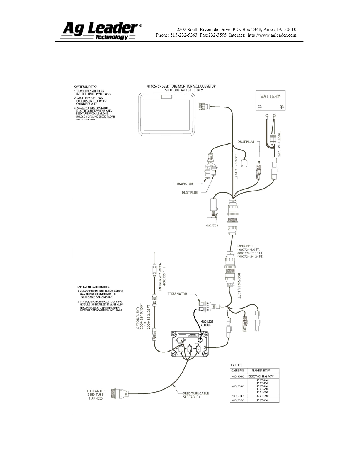
Section 2: Seed Tube Monitor Setup
Seed Tube Monitor Module – standalone configuration
Part No. 2002831-47 Rev. B
2
Page 3

Seed Tube Monitor Module – with Clutch Control
Part No. 2002831-47 Rev. B
3
Page 4

Seed Tube Monitor Module – with Hydraulic Seed Control
and Clutch Control
Part No. 2002831-47 Rev. B
4
Page 5

Section 3: Configuration Procedure
The following setup procedure describes how to configure a Seed Tube Monitor
Module. To begin this procedure, to the Configuration Tab in Planting and press the
Add button.
Note: In order for you to use this configuration at the Run screen, you must also
configure a vehicle, implement, controller and product(s). For more information on how
to configure these, consult the InSight User Manual.
Seed Tube Monitor Module Configuration
STEPS ACTION
1
2
3
4
Select Vehicle
At the Configuration Tab, press the Add button and the Operating Configuration
Wizard appears. Select an existing Vehicle from the drop-down menu, or press
the Add button and create a new vehicle with the Vehicle Setup Wizard. Press
Next to continue.
Select Implement
Using the drop-down box, select the implement you would like to use in this
configuration. If there are no implements in the list, press the New button. Press
Next to continue.
Select Planter/Seeder Type and Attachment Method
From the top drop-down menu, select the Planter setting. Then use the bottom
drop-down menu to select an appropriate attachment Method. Press Next to
continue.
Select Implement Options
Under the Planter Monitor drop-down menu, select Seed Monitor Module.
Split Rows Enabled - Check this box to enable the InSight display to log
data from the planter’s Split Row units. (For split row-enabled planters, you
will need to create separate implement configurations for Split Row and
non-Split Row operations).
Planter Section Clutch Control - Check the Planter Section Clutch
Control check box if you are using clutch control.
5
Part No. 2002831-47 Rev. B
Enter Number of Rows and Spacing
Use the up and down arrow keys to enter the number of rows and spacing.
Note: These numbers will vary depending upon the crop that you are planting.
For example, corn may require a 16 row, 30-inch spacing configuration; while
soybeans could possibly require a 31 row, 15-inch spacing configuration.
When finished, press Next.
5
Page 6

Seed Tube Monitor Module Configuration (continued)
STEPS ACTION
6
7
8
9
Enter Number of Implement Sections
Use the up and down arrow keys to enter the number of implement sections, and
press Next.
Note: Do not enter the number of individual rows. Enter the number of swath
sections that can be independently turned on and off.
Enter Distance from Hitch to Application Point
Use the numeric keypad to enter the distance from the implement hitch to the
application point (from front to back). When finished, press Next.
Enter Implement Name
Use the keyboard button to enter an Implement Name, then press Finish.
Select Operation Type
The Operating Configuration Wizard reappears, under which you must select an
operation type. Select either Area Logging (used for a Site Verification
operation) or Rate Logging/Control (used for population control).
Complete the configuration procedure by continuing through the wizard by
making selections regarding controllers, additional equipment, and Ground
Speed Source that is particular to your planting operation.
Note: After completing this configuration, in order for it to become active, you
must perform an AutoConfig procedure, which assigns individual rows to the
appropriate pins on the Seed Tube Monitor Module.
To do this, first go to the Implement Tab, press on the Seed Monitor Setup
button, and the Seed Monitor Setup screen appears, as shown at “Seed Monitor
Setup” on Section 9, page 12. Press the Sensor Configuration button and the
Sensor Configuration screen appears, as shown at “Seed Tube Sensor
Configuration” on Section 10, page 13. Press the AutoConfig button to perform
this procedure.
Part No. 2002831-47 Rev. B
6
Page 7

Section 4: Setup Menu
Part No. 2002831-47 Rev. B
7
Page 8

Section 5: SeedCommand Menu Tree
Part No. 2002831-47 Rev. B
8
Page 9

Section 6: Run Screen Functionality
Part No. 2002831-47 Rev. B
9
Page 10

Section 7: Key Settings/Functionality
Seed Tube Monitor Settings on Run Screen
The Seed Tube Monitor bar graph
consists of a number of bars representing
row units. Each bar’s row height
represents that row’s population in
comparison with the target rate which
you specify with the Target numeric
keypad (see bottom row of this table).
The Planter button brings up the Seed
Monitor Options window, which is
discussed further on “Seed Tube Monitor
Options” on Section 8, page 11.
The Rate Display and Spacing Display
are where Instantaneous Average Rate
and Spacing are displayed either for the
entire planter, or for each row,
depending upon settings in the Seed
Monitor Options.
The appearance of the Seed Tab varies,
depending upon whether the module is
being used with a Ag Leader Seed
Control module or if it used for a Site
Verification operation. If you are using a
Site Verification operation, the Seed Tab
includes the Target Population setting, as
shown at left.
The numeric keypad under the Target
portion of the Run screen allows you to
enter the target population to display on
the bar graph. Each row unit will then
appear on the bar graph showing the
seed rate percentage of the number you
entered in this keypad.
Note: If you enter an incorrect number in
this keypad, this will cause information
shown in the bar graph to appear out of
scale.
Part No. 2002831-47 Rev. B
10
Page 11

Section 8: Seed Monitor Options
Press the Planter button on the Run Screen, and the Seed Monitor Options
window appears, as shown below.
Seed Tube Monitor Options
Scan Mode specifies the Rate/Spacing on a row-by-row scan on all the planter’s row
units, displayed in sequence from left to right.
Averages
Gain
Freeze Mode specifies that the Rate/Spacing Display continuously shows only one
specified row chosen by the operator. Use the up and down arrow buttons to specify
which row to “freeze”.
Planter Mode is the default setting for the Rate/Spacing Display. This mode specifies
the instantaneous average population and seed spacing for the entire planter.
The Alarms button summons the Seed Monitor Alarms window, which shows each
individual row and the alarms threshold for that row. For more information, see “Seed
Monitor Alarms” on Section 12, page 15.
The Ignore Seed Alarms when row clutches turn off check box disables the seed
alarms when the planter clutches turn off during row turns (as an example). This box
is checked by default; uncheck if desired.
Shows the individual row number and planting rate of the row with the highest and
lowest planting rate.
Shows the population adjust value used to adjust the population if the seed tube is not
sensing the actual seed population.
For the correct Gain setting for your operation, please refer to your planter’s
operator manual.
For corn, do not change the default Gain setting of 1.
Part No. 2002831-47 Rev. B
11
Page 12

Section 9: Seed Tube Monitor Module
Setup
Press the Seed Monitor Setup button on the Implement Tab to summon the Seed
Monitor Setup window, as shown below. Here you may adjust row and ground speed
source settings, adjust sensor configuration and set alarm thresholds.
Note: New settings entered at this screen are sent directly to the Seed Tube
Monitor Module; thus you do not need to enter new configuration settings for each
planting implement unless the number of rows change.
Seed Monitor Setup
Shows the number of rows found on the planter that the Seed
Tube Monitor Module supports. Use the up and down arrows
to enter the total number of rows found on the planter.
Shows the selected Ground Speed Source input for the Seed
Tube Monitor Module.
Press the Sensor Configuration button to summon the
Sensor Configuration window, which shows which rows are
assigned to the individual pins on the Seed Tube Monitor
Module. For more information, see “Seed Tube Sensor
Configuration” on Section 10, page 13; and also “Seed
Monitor Sensor Selection” on Section 11, page 14.
Press the Alarms button to summon the Seed Monitor Alarms
window, which shows each row and the alarm threshold for
that row. For more information, see “Seed Monitor Alarms”
on Section 12, page 15.
Part No. 2002831-47 Rev. B
12
Page 13

Section 10: Seed Tube Sensor
Configuration
The Sensor Configuration window shows which rows are assigned to the
individual pins on the Seed Tube Monitor Module.
Seed Tube Sensor Configuration
The numeric keypad to move the sensor to a different location, in case
you need to make configuration changes for custom planting operations.
Note: To return to the default, press the AutoConfig button.
The Status button enables and disables a Seed Tube sensor.
Note: A row with a failed sensor can be ignored until a replacement
sensor is installed.
The AutoConfig button sends the planter settings to the Seed Tube
Monitor Module.
Note: After creating a Seed Tube Monitor Module configuration, in order
for it to become active you must perform an AutoConfig procedure.
The Remove button removes an individual Seed Tube sensor.
The row spacing keypad is where you must enter in the row spacing that
your planter will use during planting operations.
Part No. 2002831-47 Rev. B
13
Page 14

Section 11: Seed Tube Sensor
Selection
If you specified a split-row planting configuration in the drop-down list shown on
the Seed Monitor Setup window (See “Seed Tube Monitor Module Setup” on Section 9,
page 11), then the Selection window will appear (as shown below) after the first time that
you press the Sensor Configuration button on the Seed Monitor Setup window. Choose
between Standard Row or Split Row, and press OK.
Seed Monitor Setup: Selection
Note: Split-row users must configure the Seed Tube Monitor Module for both
Standard Row configurations and Split Row Configurations. Both configurations are then
saved in the module, and settings for each planting configuration are automatically
applied when you specify the machine configuration on the Run Screen.
Part No. 2002831-47 Rev. B
14
Page 15

Section 12: Seed Monitor Alarms
Pressing the Alarms button on the Seed Monitor Options window summons the
Seed Monitor Alarms window, as shown below.
Seed Monitor Alarms
Disable High
Disable Low
Select All
High
Low
The High and Low buttons assign a percentage of error that will
trigger the rate alarm.
The Disable High and Disable Low buttons deactivate the respective
high or low rate alarms.
The Select All button selects all rows so that you may change the
alarm threshold for the entire group.
Part No. 2002831-47 Rev. B
15
Page 16

Section 13: Seed Monitor Diagnostics
Specific diagnostics information, which pertains to application functions, can be
viewed when you press the Run Screen’s System button.
Note: For generalized diagnostic information, such as memory, display, CAN
device and firmware information, Input Diagnostics, Liquid Diagnostics and LED
memory states, consult the InSight User Manual.
The Seed Diagnostics Tab shows row data from rows monitored by the Seed Tube
Monitor Module, including the following:
Row unit seeds per second
Row unit seeds per acre
Seed Diagnostics
Additionally, alarms are
shown in the right
portion of the Seed
Diagnostics Tab.
In this instance, a High
Population alarm has
sounded at the Run
Screen. This alarm
appears in a list, and the
rows affected by the
alarm appear underneath.
Part No. 2002831-47 Rev. B
16
 Loading...