

Page 1
NORAC UC5 Module
Quick Reference Sheet
Section 1: NORAC UC5 Setup
To view the NORAC UC5 Setup window, go to the Implement Tab, select the
desired sprayer from the Implement list and press the NORAC UC5 Setup button. The
NORAC UC5 setup window appears, as shown below.
Note: In order for you to view this window, the NORAC UC5 Spray Height
Controller must be installed on your sprayer and this feature must be communicating on
the CAN bus.
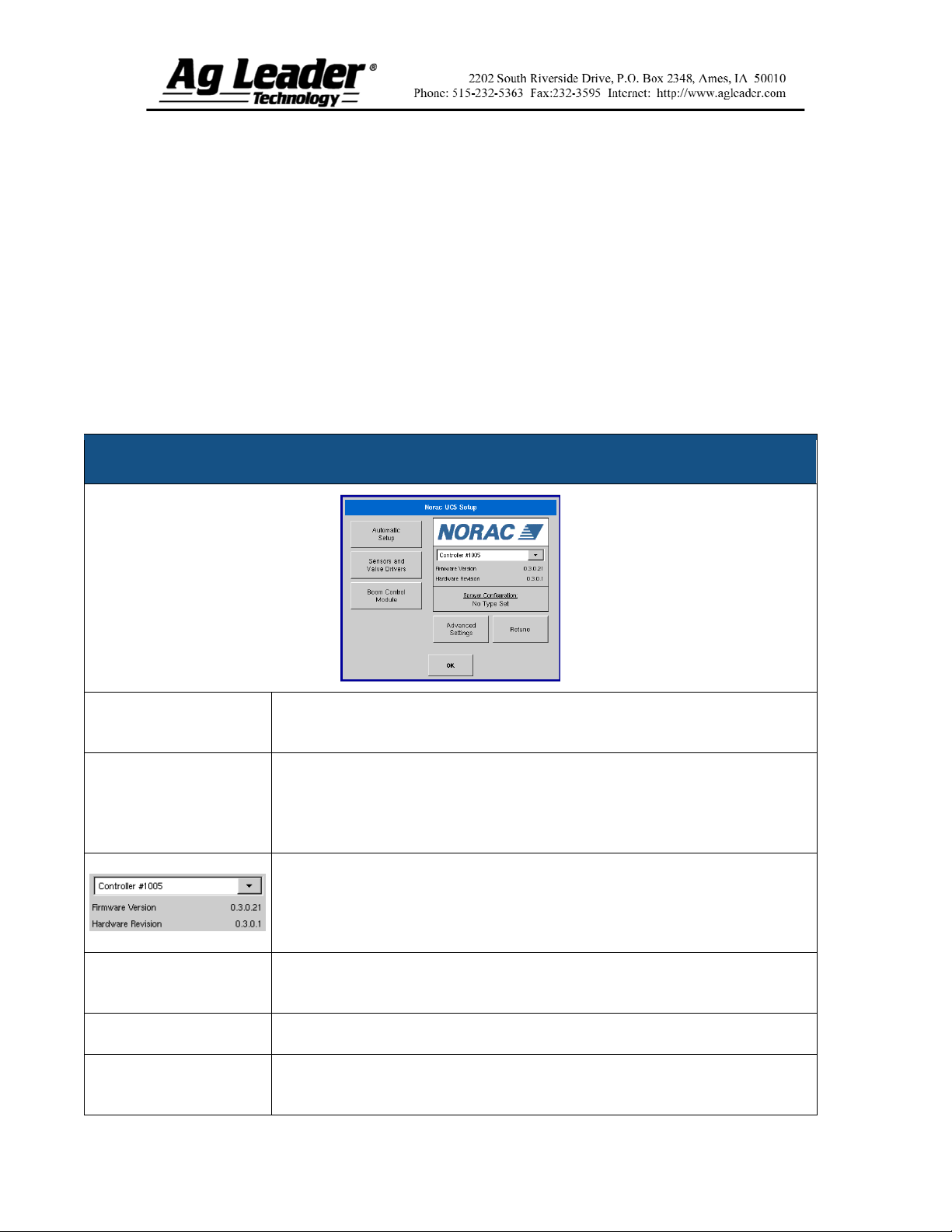
NORAC UC5 Setup Window
Automatic Setup
Sensors and Valve
Drivers
Sprayer Configuration
Advanced Settings
Retune
Loads the Select Sprayer window, which starts the Automatic Setup process.
For more information, see Section 2 on page 2.
Loads the Sensor and Valve Driver Settings window, where users can set
minimum height mode; adjust minimum height settings and manually edit
sensor, valve and input settings. For further information, see Section 4 on
page 2. Also, consult the NORAC UC5 manual for more information.
The drop down menu shows the devices communicating on the NORAC UC5
CAN Bus along with the serial number of each device. The Firmware Version
and Hardware Revisions of your NORAC UC5 devices are shown
underneath.
Displays the sprayer model configured during the Automatic Setup
procedure.
NORAC non-user menu.
Retunes the UC5 electronics to your sprayer’s hydraulics. For more
information, see Section 3 on page 2.
Part No. 2005941
1
Page 2

Section 2: Automatic Setup
Automatic Setup walks through a series of steps that configures the NORAC UC5
electronics to the sprayer hydraulic functions. You must perform an Automatic Setup
routine after the NORAC UC5 system is installed. The following items are configured
during an Automatic Setup routine:
Sprayer Make and Model
Input module wiring and configuration
Number of sensors and location
Sensor zero point
Valve deadzone and gain values
Note: For detailed Automatic Setup information, see the NORAC UC5 manual.
Section 3: Retune
From time to time it may be necessary to recalibrate (Retune) the UC5 electronics to your
sprayer’s hydraulics. Examples of such times are:
When a hydraulic solenoid valve is changed.
When the hydraulic pump is changed or adjusted.
When the normal working temperature of the hydraulic oil has shifted significantly
from when the system was previously calibrated.
If you are running a pull type sprayer and use different tractors to operate the sprayer,
you should run the Retune procedure each time the tractor is changed. If you have a flow
control for the boom hydraulics, set it prior to tuning. If you change the flow setting by
more than 20 percent, you should Retune.
Section 4: Minimum Height Settings
Pressing the Sensors and Valve Drivers button on the NORAC UC5 window opens the
Sensor and Valve Driver Settings window. The following settings appear on the General
Tab.
Minimum Height Mode
The Minimum Height Mode drop-down menu includes three selections:
Absolute: In Absolute Mode, no sensors are allowed to move closer to the target
than the minimum height setting.
Relative: In Relative Mode, no sensors are allowed to move closer to the target than
the distance of the target height minus the minimum height setting.
Disabled: Disables the minimum height mode.
Note: “Target” refers to the ground in Soil Mode, and the crop canopy in Crop Mode.
Part No. 2005941
2
Page 3
Section 5: Run Screen Environment
When the NORAC UC5 Spray Height Controller is configured on the InSight
display, the Boom Height Tab appears on the Run Screen, just behind the Application
Tab, as shown below. Note: In order for you to view these settings, you must check the
Enable Boom Height Control check box on the Implement Tab.
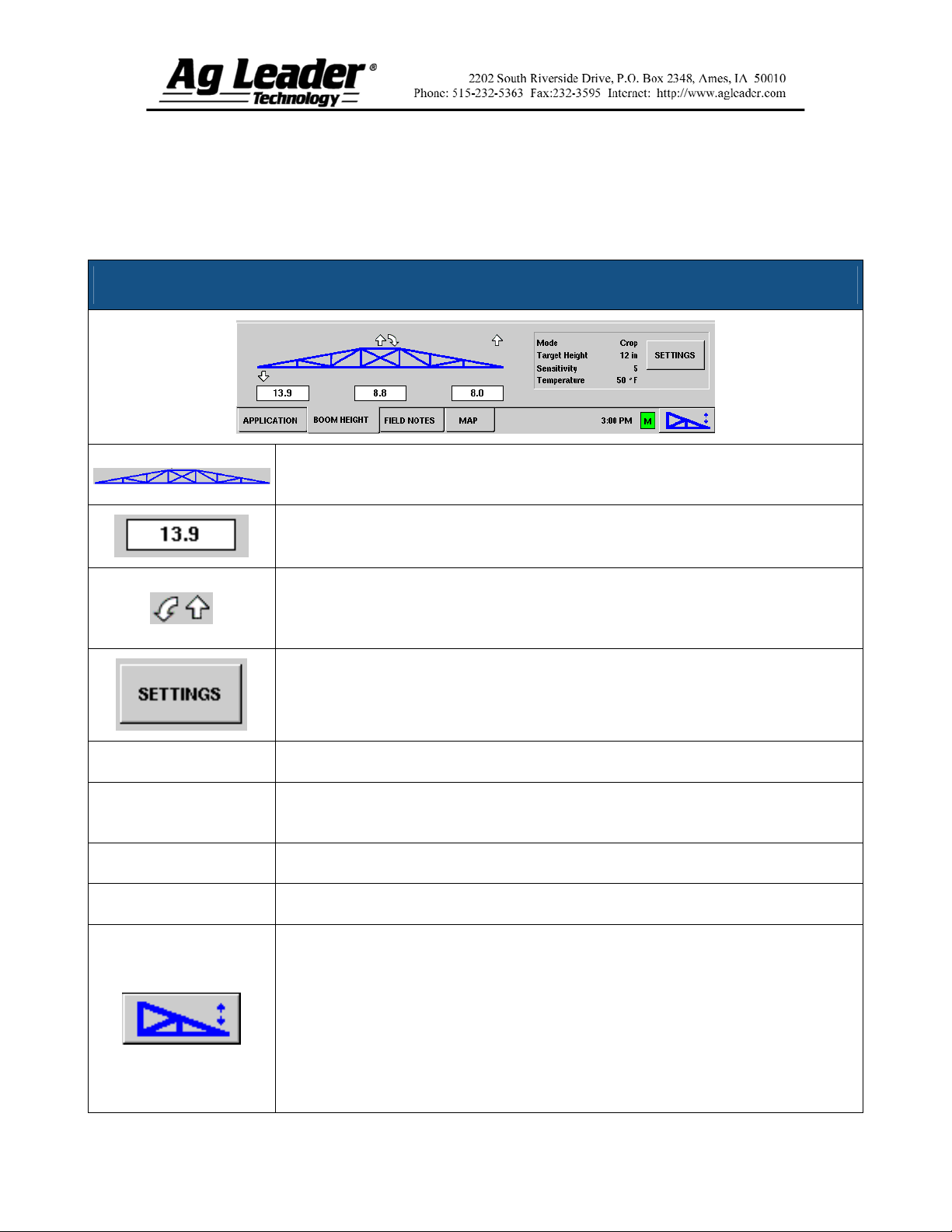
NORAC UC5 Setup Window
The Boom Icon appears as blue when in Automatic Mode; and black when in
Manual Mode. The right, left and center sections appear independently on this icon.
The numbers that appear below the Boom Icon show the distance between the
boom section and the target.
Mode
Target Height
Sensitivity
Temperature
Indicates the direction that the boom section is being commanded to move. The
arrows shown around the boom appear either 1) In Automatic Mode, or 2) When
the boom is in Manual Mode and the user is manually moving the boom section.
Loads the Boom Height Control Options window, which allows you to change the
mode, sensitivity and target height. For more information, see Section 6 on page 4.
Indicates whether the Boom is in Crop Mode or Soil Mode.
The desired boom height above the ground (for Soil Mode), or the crop canopy (for
Crop Mode).
Adjusts the boom response. Higher values make the height control more responsive.
Shows the measurement of the outside ambient air temperature.
The Engage button enables boom height control. This button can toggle back and
forth between Automatic Mode and Manual Mode.
When you enable Automatic Mode, this button turns blue and the InSight
display beeps three times.
When you disable Automatic Mode on any part of the boom and the display
switches to Manual Mode, this button turns black and the InSight display beeps
twice. If less than the full boom remains in Manual Mode, the InSight will
continue beeping twice every three seconds.
Part No. 2005941
3
Page 4

Section 6: Boom Height Control
Options
You can adjust the mode, sensitivity and target height by pressing the Settings button on
the Run Screen. The Boom Height Control Options window appears, as shown below.
Boom Height Control Options
Mode
Sensitivity
Target Height
The drop-down menu is where you can choose one of two modes:
In Soil Mode, the UC5 controls boom height relative to the distance
from the soil.
In Crop Mode, the UC5 controls boom height relative to distance from
the crop canopy.
Adjusts the boom response. Higher values make the height control more
responsive; settings range from 0-10.
User-defined desired boom height in relation to the selected control mode.
Part No. 2005941
4
 Loading...