

Page 1

Flow Meter Control Module
Quick Reference Sheet
Section 1: Configuration Procedure
The InSight’s flow meter feature allows you to create a record of product
applications. The following setup procedure describes how to configure flow meter
logging using the Application Rate module for a single product application. To begin this
procedure, go to the Configuration Tab in Application setup and press the Add button.
Flow Meter Configuration for a single product
STEPS ACTION
1
2
3
Select Single Product Configuration Type
To add a new flow meter configuration, press the Add button on the
Configuration Tab.
Select Vehicle
Select the Vehicle to be used in the configuration from the drop-down list, press
Next to continue and proceed to Step 6. Otherwise, if a new vehicle needs to be
made, press the New button.
Create New Vehicle
Select the Vehicle to be used in the configuration from the drop-down list.
4
5
Enter Vehicle Information
Use the on-screen keyboard to enter names for the Vehicle Make and Model.
Press Next to continue.
If you selected Tractor or Self-Propelled Spreader in Step 3, proceed
If you selected Self-Propelled Sprayer in Step 3, proceed to Step 8 on
Enter Vehicle Name
If you selected Tractor or Self-Propelled Spreader in Step 4, the InSight display
combines the Vehicle Make and Model for use as a Vehicle Name. Use the onscreen keyboard to edit the vehicle name, if desired. Press Finish to complete
Vehicle setup and continue with the configuration process.
If you selected Tractor in Step 3, press Finish and proceed to Step 6.
If you selected Self-Propelled Spreader in Step 3, press Finish and
Part No. 2002831-32 Rev. B
to Step 5 on page 2.
page 2.
proceed to Step 13.
1
Page 2

Flow Meter Configuration for a single product (continued)
STEPS ACTION
6
7
8
9
10
Select Implement
Select an existing Implement from the Implement List. If a new Implement
needs to be created, press the New button to launch the Implement Setup
Wizard.
Select Implement Attachment Method
The Implement Setup Wizard appears. Use the drop-down list to select an
implement attachment method: Rear Drawbar, Rear 3-Point Hitch, Front
Drawbar or Front 3-Point Hitch. Press Next to continue.
Note: Spinner Spreader users should check the Spinner Spreader Implement
Type check box, press Next and proceed to Step 11.
Enter Full Swath Width
Enter the full width of the spray boom expressed in feet (or meters for metric
applications). Press Next to continue.
Enter Number of Boom Sections
Use the up and down arrow buttons to enter the total number of boom sections.
Press Next to continue.
Enter Boom Section Widths from Left to Right
The system automatically divides the boom into equal length sections. Select
individual sections and use the on-screen keypad to edit boom section lengths if
needed. Press Next to continue.
11
12
13
14
Enter Distance from Hitch to Application Point
Use the numeric keypad to enter the distance from the hitch to the application
point. Press Next to continue.
Enter Implement Name
Use the keyboard button to enter a name for the implement. Press the Finish
button to complete the implement setup process and continue with the Operating
Configuration Wizard.
Select Operating Mode
Use the drop-down list to select Rate Logging/Control. Press Next to continue.
Select Controller
Use the drop-down list to select the desired controller. If the controller you wish
to use is not in the list, press New.
Part No. 2002831-32 Rev. B
2
Page 3

Flow Meter Configuration for a single product (continued)
STEPS ACTION
15
16
17
18
19
Select Flow Meter
Since we are setting up a single, liquid product application with a flow meter,
choose the following settings:
Select Flow Meter from the Device drop-down list.
Select Liquid or Granular from the Flow Meter Type drop-down list.
Press Next when finished.
Enter Flow Meter Calibration Number
Enter the Pulses/Unit calibration number for the product flow meter. Press Next
to continue.
Enter Suggested Controller Name
The InSight display assigns a default name to the controller. Use the on-screen
keyboard to edit this name, if desired. Press Finish to complete Controller setup
and continue with the configuration process.
Select Implement Switch
Select None for the Implement Switch. Press Next to continue.
Select Container
Use the drop-down list to select the Container that will be used with the
equipment. Examples of containers are sprayer tanks and NH
to add a container if required. Otherwise, press Next to continue and skip ahead
to Step 22.
tanks. Press New
3
20
21
22
23
Part No. 2002831-32 Rev. B
Enter Container Capacity and Units
Enter the container Capacity using the on-screen keypad. Select the Units used
the represent the Capacity of the container. Press Next to continue.
Enter Container Name and Location
Use the on-screen keyboard to assign a name to the Container. Press Finish to
complete the Container setup process and continue with the Operating
Configuration Wizard.
Select Ground Speed Source
Select your ground speed source. If you will be using GPS as the primary you
will need to select a secondary source. Press Next to continue.
Enter Suggested Name for Configuration
Use the keyboard button to edit the suggested configuration name. Press Finish
to complete the configuration setup.
The configuration should now be displayed in the configuration list.
3
Page 4
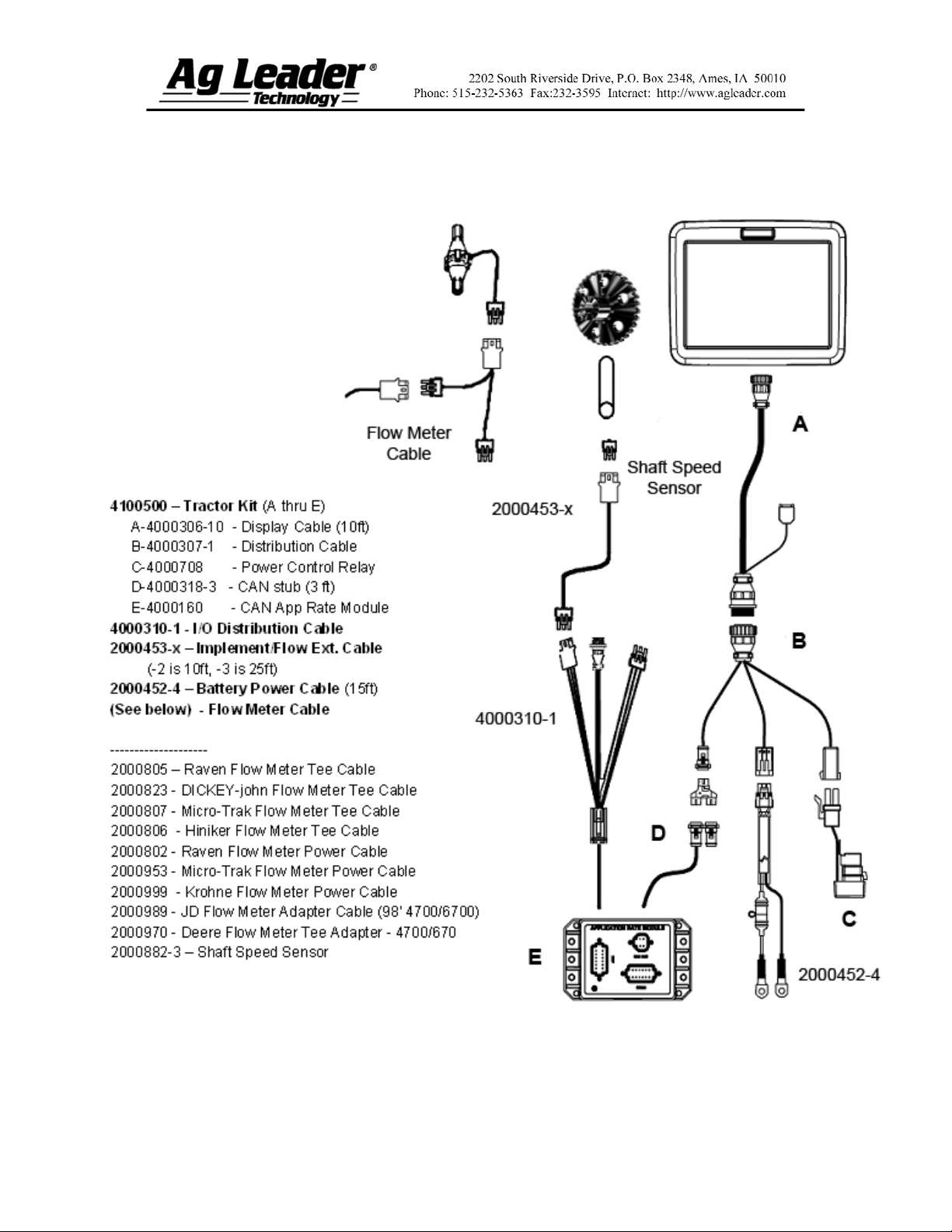
Section 2: Flow Meter Hardware
Setup
Part No. 2002831-32 Rev. B
4
Page 5
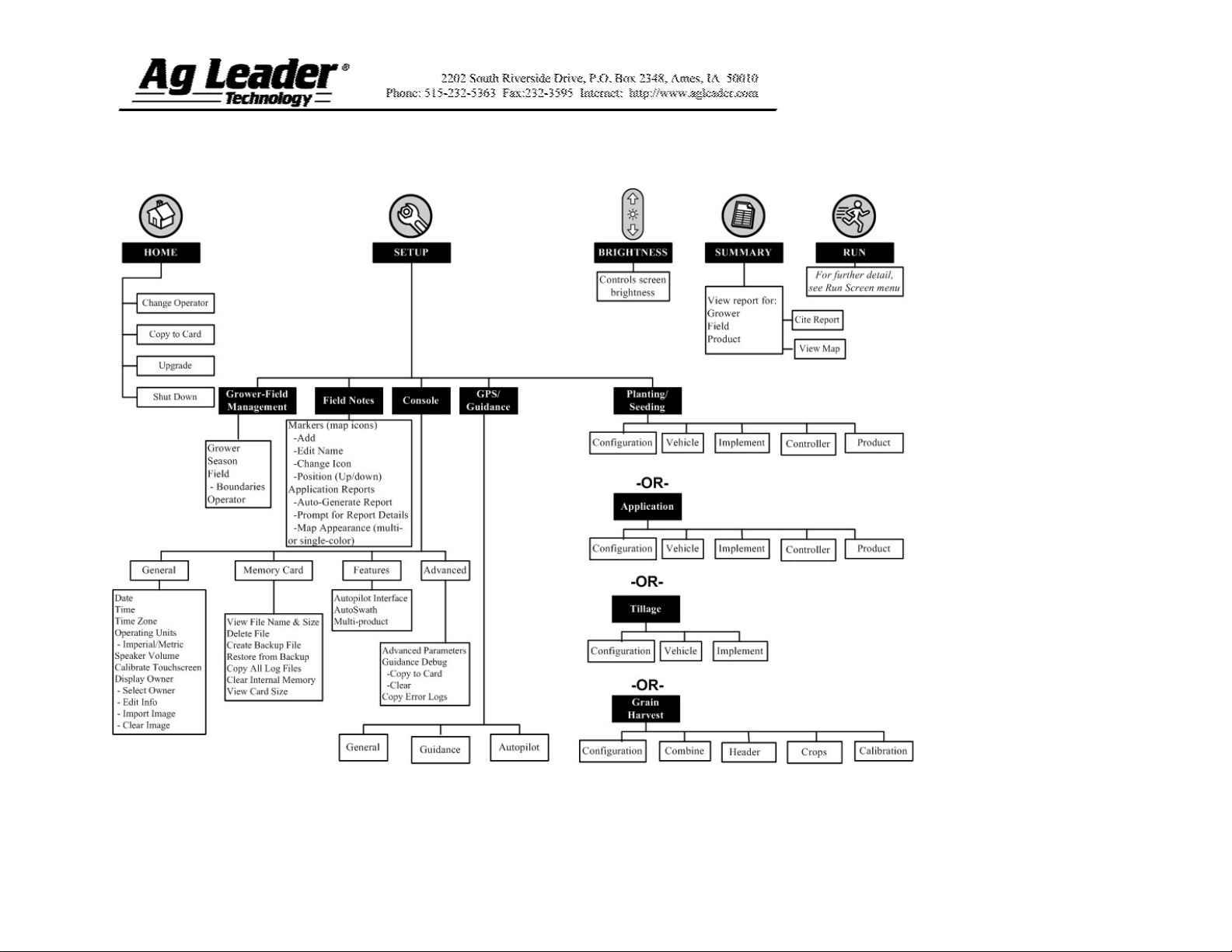
Section 3: Setup Menu
Part No. 2002831-32 Rev. B
5
Page 6
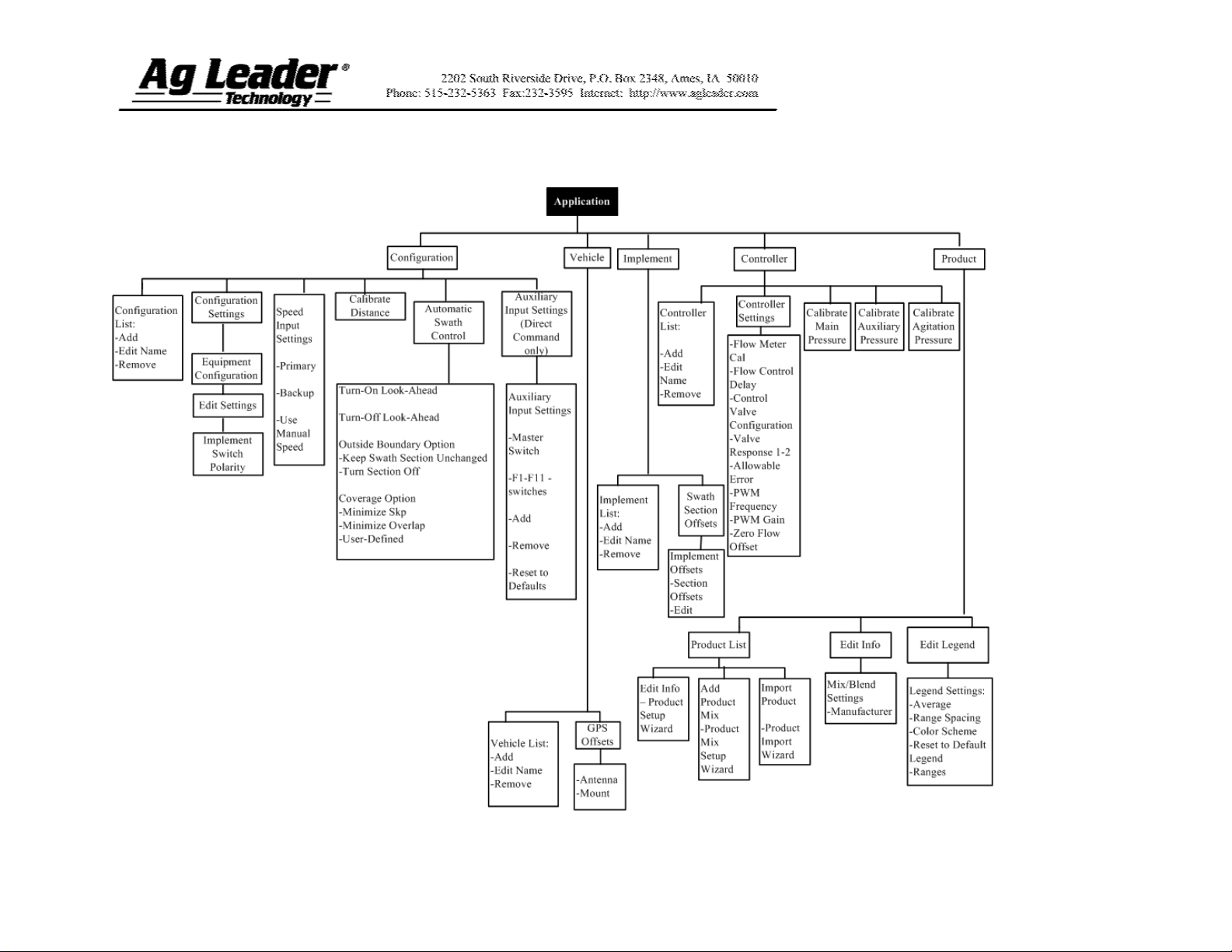
Section 3: Application Menu Tree
Part No. 2002831-32 Rev. B
6
Page 7
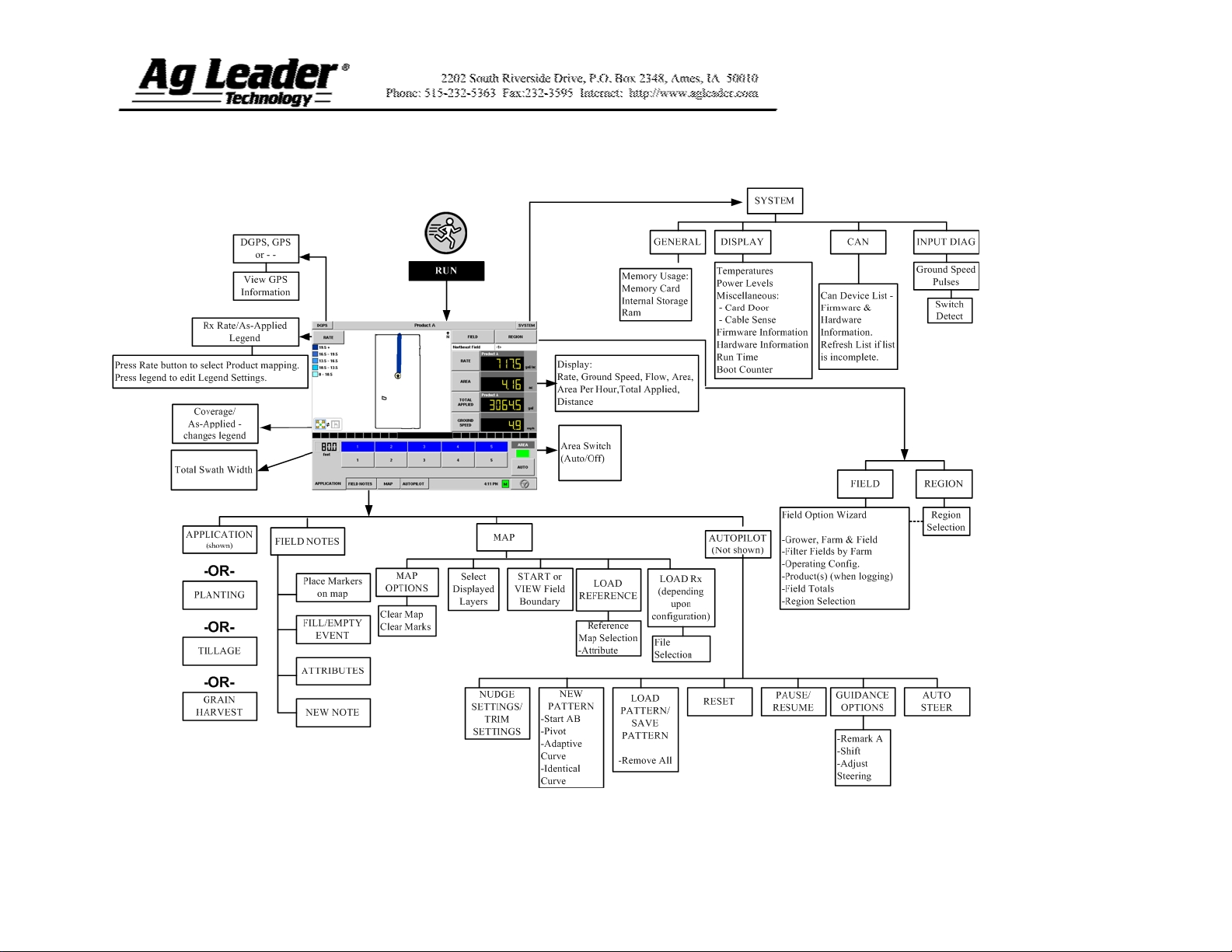
Section 4: Run Screen Functionality
Part No. 2002831-32 Rev. B
7
Page 8

Section 5: Key Settings/Functionality
Flow Meter Run Screen Settings
You can use the Run Screen
swath section buttons to turn
off individual section logging
on the InSight display if you
wish to apply product using
less than a full swath width.
Note: Turning the Flow Meter
section logging on and off in
the InSight display does not
actually affect their in-field
performance – only their
InSight display logging status.
The swath section width
displays swath width.
Area will automatically be
counted when the InSight
display is recording pulses
from the flow meter and the
display shows a ground speed.
The button should read Auto
to count area. If you do not
want to count area when you
are applying product, press the
Auto button to disable the area
count. The button will display
Off.
The Master Switch Indicator
shows if the master switch is
on (green) or off (red). The
master switch is shown in the
F1 position on the Auxiliary
Input Settings window.
Part No. 2002831-32 Rev. B
8
Page 9

New Controller Product Notes
PRODUCT NOTES
Raven
Tee Jet
Mid-Tech
Raven flow meter tags represent pulses per 10 gallons. Divide Raven’s
tag number by 10 if this is the case.
Tee Jet meter calibration numbers are pulses per liter. To conver the
number, multiply the value found on the flow meter by 3.79 to find the
pulses per gallon needed for the InSight display.
Mid-Tech flow meters sometimes have a cable with a module. The
calibration number found on this cable is in pulses per gallon/divided
by 16. The InSight display should bypass this module and plug directly
into the flow meter. If that is the case then multiply the calibration
number by 16 before entering it into the InSight display.
Appendix: Dickey-john Flow Meter Calibrations
Note: The flow sensor constant is stamped on the Dickey-john flow meter. Refer to the
Dickey-john manual for information on the density setting.
Flow meter calibration for Anhydrous Ammonia (NH3)
Use the following formula for flow meter calibration for Dickey-john reading pounds of
anhydrous ammonia.
3
Flow sensor constant (pulses/in
) x 1728 (in3/ft3) x 5.11 (lbs. of anhydrous/gal.)
Density (lbs. of anhydrous/ft.3)
Flow meter calibration for nitrogen (N)
Use the following formula for flow meter calibration for Dickey-john reading pounds of
Nitrogen.
Flow sensor constant (pulses/in
3
) x 1728 (in3/ft3) x 4.22 (lbs. of Nitrogen/gal.)
Density (lbs. of Nitrogen/ft.3)
Part No. 2002831-32 Rev. B
9
 Loading...