

Page 1
InSight™ Firmware Version 6.0
Cotton Harvest Insert
573
PN: 2002881 Rev.F
Page 2

InSight™ User Guide - Cotton Harvest Insert
ABOUT THIS INSERT
This Cotton Harvest Insert is designed to be included in the back of your current InSight User Manual,
immediately behind the Document Change Request Form.
Throughout this insert a number of cross-references are included which refer to other chapters of the
InSight Manual. To ensure that these cross-references accurately cite correct page numbers, please
ensure that the revision of this insert (the alphabet letter found at the bottom right-hand corner of the
page) matches the current revision of your InSight User Manual.
As with other chapters in the InSight User Manual, an index is provided at the back of this insert that
refers to terms found in this specific chapter.
574
PN: 2002881 Rev.F
Page 3

InSight™ User Guide - Cotton Harvest Insert
INSTALLATION
TYPICAL SYSTEM WIRING DIAGRAM
Yield monitor installation kits are specific to each supported picker model. Installation specific
instructions and diagrams are packaged with each kit.
575
PN: 2002881 Rev.F
Page 4

InSight™ User Guide - Cotton Harvest Insert
COTTON SETUP
COTTON HARVEST MENU
PN: 2002881 Rev.F
576
Page 5

InSight™ Firmware Version 6.0
COTTON SETUP TABS
CONFIGURATION
The Cotton Harvest setup pages contain all the necessary settings to configure the system for logging,
mapping, and rate control for planting operations. The combination of Configuration, Combine, Header,
Crop and Calibration are referred to as a Configuration within the InSight system.
Cotton Harvest Setup
Tab
Configuration
Picker
Crop
Calibration
Cotton Harvest configurations
Description
The Configuration Tab is where you can add and edit operating
configurations. For more information, see “Configuration” on
page 577.
The Picker Tab is where you can set up and configure additional
pickers. For more information, see “Picker Tab Buttons” on
page 584.
The Crop Tab is where you can add and edit crops. For more
information, see “Crop Tab Buttons” on page 593.
The Calibration Tab is where you can perform calibrations. For
more information, see “Calibration Tab” on page 599.
PN: 2002881 Rev.F
577
Page 6

InSight™ User Guide - Cotton Harvest Insert
CONFIGURATION TAB BUTTONS
The Configuration Tab is where cotton harvest configurations are made and displayed. Press the Setup
button and then the Cotton Harvest button to reach this screen.
• To see a Cotton Harvest Configuration Menu, see “Cotton Harvest Menu” on page 576.
• For required setup before this configuration can be used, see “Setup Tips” on page 17.
Cotton Configuration Tab
Button Description
Press to add a new cotton configuration. An on-screen wizard
will walk you through the setup process in a step-by-step
manner. New pickers can be created during the setup process.
For more detailed information, see “Adding A New
Configuration” on page 579.
Press to edit the name of a selected configuration. The onscreen keyboard will be displayed to complete the desired text
edits.
Press to remove a configuration. The picker will not be
deleted.
When deleting a configuration all regions and
harvest data logged with that configuration will be deleted!
Press to display and edit settings specific to a vehicle, picker
and controller combination. For more information, see
“Configuration Settings” on page 583.
578
PN: 2002881 Rev.F
Page 7

InSight™ Firmware Version 6.0
ADDING A NEW CONFIGURATION
To add a new configuration press the Add button. The Configuration Setup Wizard appears, as shown
below.
Step 1: Select picker from Configuration
Setup Wizard
Press New to add a new picker or select an existing one from
the list. For detailed information, see “Adding A New Picker”
on page 586.
Press Next to continue.
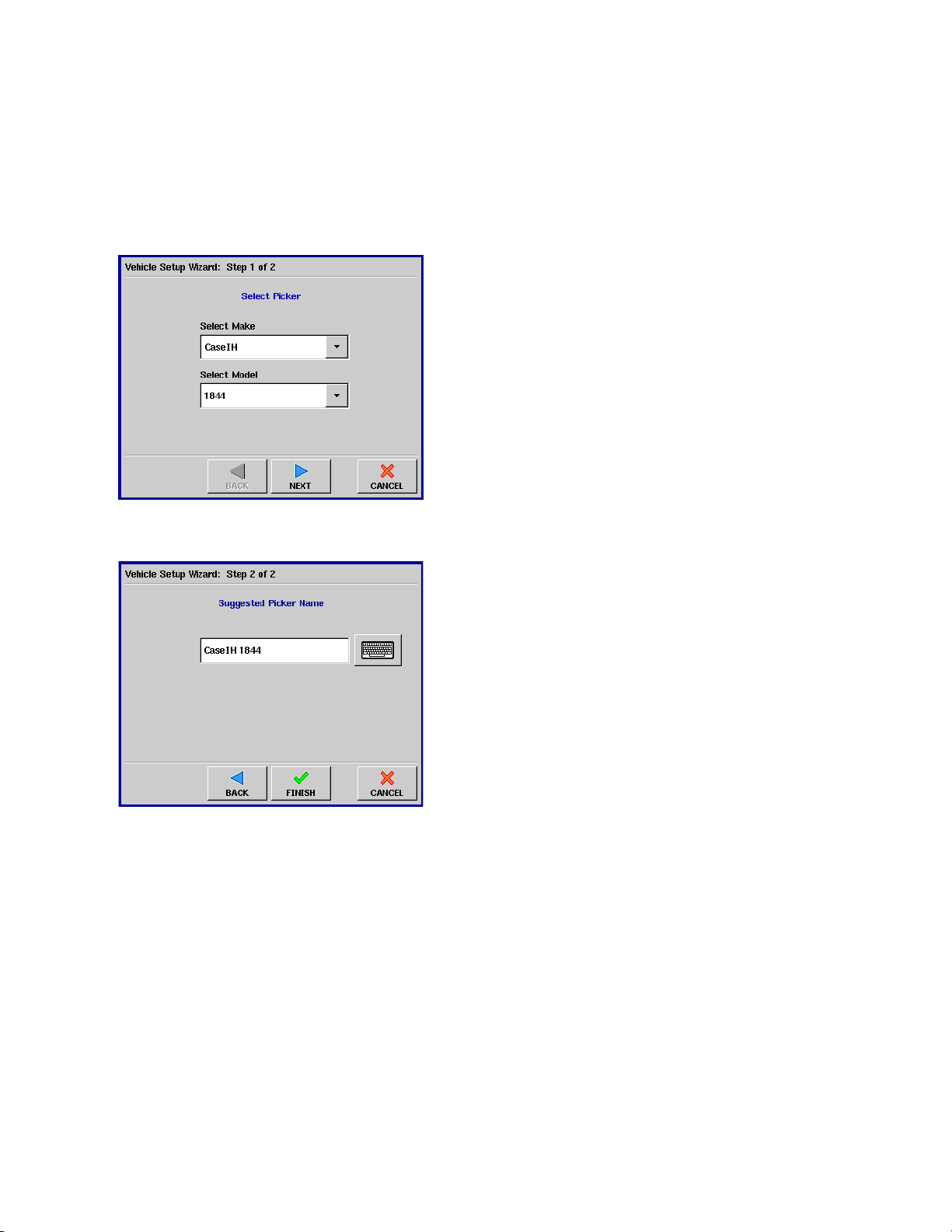
Step 2: Select picker from Vehicle Setup
Wizard
Step 3: Enter suggested picker name
If you pressed New, the Vehicle Setup Wizard appears, as
shown at left. A list of all cotton pickers manufactured by
John Deere and Case IH which are supported by the InSight
monitor is provided in the Select Make and Select Model
drop-down menus. Select your make and model, then press
Next.
Use the keyboard button to edit the name of the picker.
Press Finish to continue, and you will return to the next
window in the Configuration Setup Wizard.
PN: 2002881 Rev.F
579
Page 8

InSight™ User Guide - Cotton Harvest Insert
ADDING A NEW CONFIGURATION (CONTINUED)
Auxiliary Step: Select Head Type (John
Deere vehicles only)
If you have entered in a John Deere make and model, you
will see an auxiliary step of the Configuration Setup Wizard.
Select either the inline or convention header type.
• The Inline head type configures the InSight monitor to
receive data from one sensor per row. Most current John
Deere pickers use this header type.
• The Conventional head type configures the InSight
monitor to receive data from two sensors per row. Some
older John Deere pickers use this head type.
After making your selection, press Next to continue.
Step 4: Enter Number of Rows and Full
Swath
Use the up and down arrows to enter the number of rows;
then use the numeric keypad to enter the full swath width
of the header. Press Next to continue.
580
PN: 2002881 Rev.F
Page 9

InSight™ Firmware Version 6.0
ADDING A NEW CONFIGURATION (CONTINUED)
Step 5: Enter header offset
If the header of your vehicle is mounted asymmetrically to
the vehicle’s center, you must enter in the offset distance.
At the Header Offset window shown at bottom left, you can
compensate for the distance between the center of the
vehicle and the center of the header’s swath. Use the
numeric keypad to enter this distance, and then use the
drop-down menu to enter the direction.
Press Next to continue.
Even after you have entered in the header offset
distance number here, you can still edit this number later.
For more information, see “Configuration Settings” on
page 583.
PN: 2002881 Rev.F
581
Page 10

InSight™ User Guide - Cotton Harvest Insert
ADDING A NEW CONFIGURATION (CONTINUED)
Step 6: Enter Sensor Configuration
The Sensor Configuration Window appears, showing the
rows being harvested. Press the checkboxes that correspond
to your sensor configuration. In the example at left, the
operator has selected four sensors on four rows.
In order to log data on the Run screen, you must
specify the correct sensor configuration. Otherwise, when
you attempt to set up an operating configuration at the
Run screen’s Field Operation Wizard, you will see an error
message stating that “The cotton flow sensor
configuration does not match the active picker.”
Step 7: Enter Ground Speed Source
Step 8: Enter Suggested Name for
Configuration
Select the ground speed source. If you will be using GPS as
the primary you will need to select a secondary source. Press
Next when finished.
Use the default name or enter in a new name for the
configuration.
Press Finish to complete the configuration process.
582
PN: 2002881 Rev.F
Page 11

InSight™ Firmware Version 6.0
CONFIGURATION SETTINGS
To access the Configuration Settings window, first highlight a configuration in the list and then press the
Configuration Settings button.
Configuration Settings window
Setting Description
The Header Offset shows the distance between the
centerline of the vehicle and the center of the header’s
swath. To change these settings, use the numeric keypad to
enter this distance, then use the drop-down menu to enter
the direction.
The Ground Speed Sensor area shows the primary and
secondary ground speed source.
The Active Rows area shows which rows are equipped with
sensors. If you wish to change these settings, press the
checkboxes that correspond to the number of sensors in your
configuration. In the example at left, the operator has
selected four sensors on four rows.
In order to log data on the Run screen, you must
specify the correct sensor configuration. Otherwise, when
you attempt to set up an operating configuration at the
Run screen’s Field Operation Wizard, you will see an error
message stating that “The cotton flow sensor
configuration does not match the active picker.”
PN: 2002881 Rev.F
583
Page 12

InSight™ User Guide - Cotton Harvest Insert
PICKER CONFIGURATION
PICKER TAB BUTTONS
The Picker Tab provides functionality for setting up and configuring additional pickers. This tab displays a
Picker List, which will show any pickers that have already been created. The Picker Tab also includes
functionality for Header Sensor and Distance calibrations, which must be performed prior to the start of
the cotton harvest season. To see a Cotton Configuration menu that includes information on the Picker
Tab, see “Cotton Harvest Menu” on page 576.
Picker Setup Tab
Button Description
The Add button allows you to add a new picker. A wizard will walk you
through setting up the picker. For detailed information, see “Adding A New
Picker” on page 586.
The Edit Name button allows you to edit the name of a picker in the list. To
edit, highlight the name of a picker in the list and then press this button. Use
the on-screen keyboard to edit the name.
The Remove button allows you to remove a picker. The configuration and any
regions and harvest data logged with it will be deleted.
When deleting a picker, any configurations using it will be
deleted. All regions and cotton harvest data logged with the configuration will
also be deleted!
584
The Picker Settings button allows you to view fan speed sensor settings. For
more information, see “Picker Settings” on page 587.
PN: 2002881 Rev.F
Page 13

PICKER TAB BUTTONS (CONTINUED)
Button Description
The Sensor Settings button opens the Sensor Settings window, where you can
edit the Low Signal Alarm and Zero Flow Threshold. For more information, see
“Sensor Settings” on page 588.
The GPS Offsets button allows you to specify the location of the GPS antenna
in relation to the vehicle. A wizard will walk you through these edits. For more
information, see “GPS Offsets” on page 589.
The Calibrate Distance button calibrates the radar, track or wheel speed
sensor. For more information, see “Calibrate Distance” on page 590.
InSight™ Firmware Version 6.0
The Calibrate Header Sensor button launches the Header Sensor Calibration
Wizard, which will walk you through calibrating the header sensor that turns
area logging on and off. For more information, see “Calibrating The Header
Sensor” on page 592.
PN: 2002881 Rev.F
585
Page 14
InSight™ User Guide - Cotton Harvest Insert
ADDING A NEW PICKER
To start the process of adding a new picker press the Add button. The Vehicle Setup Wizard appears, as
shown below.
Step1: Select Make and Model
Select the correct picker make and model from
the list boxes.
Press Next to continue.
Step 2: Edit Name
Use the keyboard button to edit the name of
the picker.
Press FINISH to complete the setup process.
586
PN: 2002881 Rev.F
Page 15

InSight™ Firmware Version 6.0
PICKER SETTINGS
The Cotton Picker Settings window contains fan speed sensor settings. To access this window, press the
Picker Settings button on the Picker Tab.
Cotton Picker Settings
Fan Speed Sensor Setting Description
The Use Fan Speed checkbox specifies that the fan speed
must be running at a minimum of 2,500 RPM before data
logging will begin. This box is checked by default.
This setting can be unchecked if you are having
problems with the fan speed sensor. When unchecked,
the InSight monitor will not require a minimum fan
speed for logging data. Instead, it will log data anytime
the Master Button is on Auto.
The pulses per revolution (pls/rev) setting is the number of
pulses generated for one revolution of the fan, and is preset for the factory-installed sensor on your machine. If you
replace a sensor, or believe the displayed fan speed to be
incorrect, you should verify this setting; and if necessary,
you can edit this number.
PN: 2002881 Rev.F
587
Page 16
InSight™ User Guide - Cotton Harvest Insert
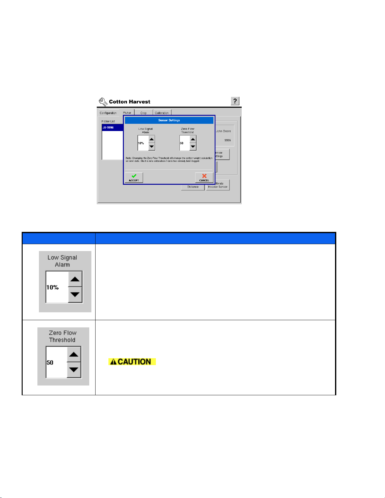
SENSOR SETTINGS
The Sensor Settings window contains values of settings that affect the operation of the picker’s cotton
flow sensors. You can access this window by pressing the Sensor Settings button on the Picker Tab.
Sensor Settings Window
Setting Description
The Low Signal Alarm box contains a percentage value that sets the threshold
for the sensors’ low signal strength alarm. Increasing this amount will make
the alarm threshold more sensitive; while decreasing it will make the alarm
threshold less sensitive. A setting of 0 will disable the low signal strength
alarm.
The Zero Flow Threshold box is a setting that compensates for the vibration of
the sensors inside the picker’s chutes.
Adjusting this value will change the current calibration.
The current calibration should be retired before changing this value. After
changing this value, you will need to perform a new calibration.
588
PN: 2002881 Rev.F
Page 17

InSight™ Firmware Version 6.0
GPS OFFSETS
After you complete the initial process of setting up a Picker, you must configure advanced GPS Offsets.
The GPS Offsets define where machine rear axle, hitch, and product placement is in relation to the GPS
antenna. These settings are used by mapping and product control. To do this, press the GPS Offsets
button, and the GPS Offsets window appears, as shown below.
Antenna Offsets
The Antenna Tab contains three different
settings. Accuracy when measuring for a specific
setting is essential to ensure proper machine
performance.
• Measure and enter the horizontal distance
from the rear axle to the position of the GPS
antenna. Select In Front or Behind from the list
box to indicate the position of the antenna in
relation to the rear axle.
• Measure and enter the horizontal distance
from the centerline of the vehicle to the position
of the GPS antenna. Select Left or Right to
indicate the position from the vehicle centerline.
• Measure and enter the vertical height of the
antenna above the ground.
Head Offset
The Head Tab allows you to enter in the distance
from the head attachment point to the rear axle.
Use the numeric keypad to enter in the distance
to the axle.
PN: 2002881 Rev.F
589
Page 18
InSight™ User Guide - Cotton Harvest Insert
CALIBRATE DISTANCE
The following procedure describes a speed sensor calibration. Before beginning, keep in mind these two
tips:
• Before beginning the speed sensor calibration, you should mark a measured distance to drive. The
default distance currently in the InSight monitor (and the recommended distance) is 100 feet, or 50
meters if using metric measurements.
• For the most accurate results, this calibration should be performed in field conditions (not on gravel or
paved roads)
To begin, first select a Picker from the list and press the Calibrate Distance button to calibrate the radar,
track or wheel speed sensor.
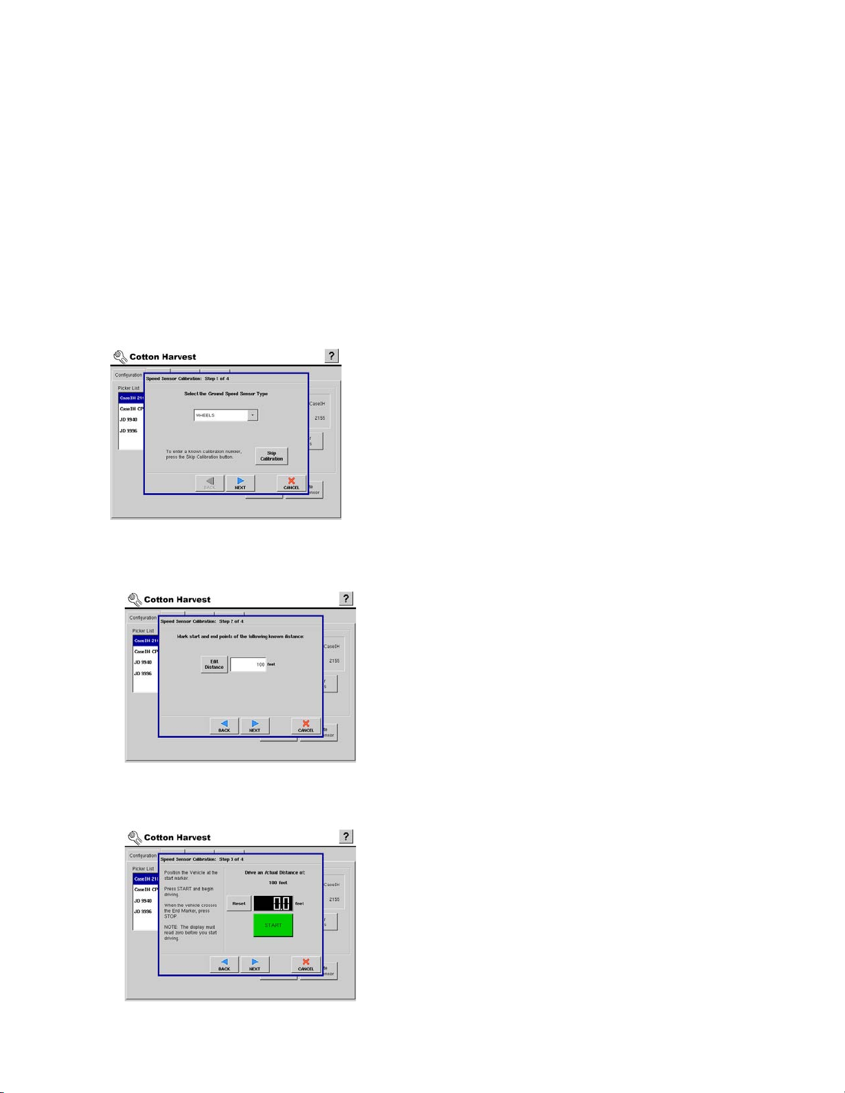
Step 1: Select Speed Input
Select the sensor type to calibrate and press
NEXT to continue.
Step 2: Calibration Distance
Step 3: Start Driving Course
The system defaults to 100 feet (or, if using
metric, 50 meters) distance for calibration.
Press Edit Distance to change if needed. This
value must match the actual distance of the
course driven for calibration.
Press NEXT to continue.
Follow the on-screen directions and press START
to begin the calibration process.
590
PN: 2002881 Rev.F
Page 19

CALIBRATE DISTANCE (CONTINUED)
Step 4: Course Completed
Drive vehicle over the measured course and
press STOP.
Press NEXT to continue to final step.
Step 5: Calibration Completed
Press FINISH to complete calibration and store
the calculated value.
InSight™ Firmware Version 6.0
It is recommended that you run the
distance calibration twice to confirm an
accurate calibration.
Calibration settings can be manually
adjusted if desired by pressing Enter CAL
Number and making small changes to the
setting.
PN: 2002881 Rev.F
591
Page 20

InSight™ User Guide - Cotton Harvest Insert
CALIBRATING THE HEADER SENSOR
Prior to logging cotton data, you must calibrate the header sensor. Crops must be set up within the
system to proceed with the calibration routine. Select the correct header from the list and press the
Calibrate Header Sensor button, located on the Picker Tab.
Step 1: Read Instructions
Read the header sensor calibration instructions fully
before proceeding.
Press Next to start the calibration process.
Step 2: Set Max and Min
Step 3: Set Stop Height
Maximum and minimum header height settings.
1. Raise the header all of the way up and press Set Max.
2. Lower the header all of the way down and press Set
Min.
This determines the full operating range of the header.
Press Next to continue.
Raise or lower the header to the height where you
would like to have the area logging turn on and off.
Press Set Height.
The position relating to the Stop Height will be
represented as a percentage. (17% in the example to
the left).
Move the header above and below the Stop Height.
When below the Stop Height the dialog will indicate
Down, when above the Stop Height the dialog will
indicate UP.
To clear Min, Max, and Stop Height, press Reset.
592
If Reset is pressed, the sensor will
have to be calibrated!
PN: 2002881 Rev.F
Page 21

InSight™ Firmware Version 6.0
SETTING UP CROPS
CROP TAB BUTTONS
Crops and crop varieties are added and edited on the Crop Tab. The crop list shows all crops and varieties
that have been created and are available for use.
To see a Cotton Harvest Configuration Menu that includes detailed information on the Crop Tab, see
“Cotton Harvest Menu” on page 576.
Crops Setup Tab
Button Description
The Add Crop button allows you to add a new crop. A wizard will
walk you through setting up the crop. For detailed information
see “Adding A New Crop” on page 595.
Press the Add Variety button to add a new variety and associate
that variety with a crop type. For detailed information see “Adding
Additional New Varieties” on page 597.
The Edit Name button allows you to edit the name of a crop or
variety in the list. To edit, highlight the name of a crop or variety
in the list and then press this button. Use the on screen keyboard
to edit the name.
Press the Remove button to remove a crop or variety.
PN: 2002881 Rev.F
When a crop or variety is removed, all regions
and the logged harvest data relating to that crop or variety will
be deleted!
593
Page 22

InSight™ User Guide - Cotton Harvest Insert
CROP TAB BUTTONS (CONTINUED)
Button Description
The Crop Settings box displays the Lint Percentage and Bale Size
for the selected crop.
The Edit button allows you to change the values from the default.
To edit, highlight a crop in the crops list and press Edit.
Press the Edit Legend button to change the default legend for the
selected crop type. The Legend Settings that are made here will
affect all regions of that crop type. For additional information,
see “Edit Legend” on page 598 .
594
PN: 2002881 Rev.F
Page 23

InSight™ Firmware Version 6.0
ADDING A NEW CROP
To add a new crop press the Add Crop button. The Cotton Crop Wizard appears, as shown below.
Step 1: Edit Crop Name (optional)
The default name of Cotton appears in the
Suggested Name box. If necessary, use the
keyboard button to edit the name.
Press Next to continue.
Step 2: Add Varieties
Press Add to set up seed varieties for the crop
type.
Any seed varieties set up in the planting
setup will already be present in the list.
Press Finish. The Select Units window will appear
next.
PN: 2002881 Rev.F
595
Page 24

InSight™ User Guide - Cotton Harvest Insert
ADDING A NEW CROP (CONTINUED)
Step 3: Select Units
Step 4: Enter Variety Details
Select the units for the crop.
Press Next to continue.
Use the keyboard buttons to enter the
manufacturer and the variety or hybrid name.
The manufacturer name is optional.
Press Finish to complete setting up the seed
variety.
596
PN: 2002881 Rev.F
Page 25

InSight™ Firmware Version 6.0
ADDING ADDITIONAL NEW VARIETIES
To enter additional varieties, go to the Crop Tab and press the Add Variety button. The Variety Setup
Wizard appears, as shown below.
Step 1: Select A Crop
Select the planted units.
Press Next to continue.
Step 2: Enter Variety Details
Use the keyboard buttons to enter the
manufacturer and the variety name.
The manufacturer name is optional.
Press Finish to complete setting up the seed
variety.
PN: 2002881 Rev.F
597
Page 26

InSight™ User Guide - Cotton Harvest Insert
EDIT LEGEND
To access the Legend Settings window press the Edit Legend button.
Item Description
Press to edit average crop yield value.
Press to edit the legend range spacing value.
Selects the color scheme to use for the yield legend.
Press to reset legend to the system default.
598
Selects the number of ranges to display in the legend.
PN: 2002881 Rev.F
Page 27

InSight™ Firmware Version 6.0
COTTON CALIBRATION
CALIBRATION TAB
The Calibration Tab is where weight calibrations and Field Area calibrations are done. A weight
calibration must be completed after harvest has started. (For Header Sensor and Distance calibrations, see
“Picker Configuration” on page 584).
For a Cotton Configuration Menu that includes detailed information on the Calibration Tab, see “Cotton
Harvest Menu” on page 576.
Calibration Setup Tab
Settings Description
The Crop Type box lists the crop you are about to calibrate.
The Calibration drop-down menu lists all of the previous
calibrations that you have performed, and the date that these
calibrations were created.
The Field Area Calibration button will adjust the total area for
a field. For more information on the Field Area Calibration
button, see “Field Area Calibration” on page 601.
The Enter Weight button allows you to enter the measured
weight for a region. For more information, see “Entering Actual
Load Weights” on page 603.
PN: 2002881 Rev.F
599
Page 28

InSight™ User Guide - Cotton Harvest Insert
CALIBRATION TAB (CONTINUED)
Settings Description
The Show Calibration button allows you to view or manually
change the calibration numbers. To view the updated
calibration numbers, press the Show Calibration button after
you have performed a weight calibration. For more
information, see “Show Calibration” on page 602 and also
“Adding a New Calibration” on page 605.
The Move Regions button allows you to move a region from
one calibration to another. For more information, see “Moving
Regions Between Calibrations” on page 608.
After you have checked your calibration regions and entered
actual weights, you can perform the weight calibration. Check
the loads you wish to use in the calibration and then press the
Perform Calibration button. For more information, see
“Perform Calibration” on page 604.
600
PN: 2002881 Rev.F
Page 29

InSight™ Firmware Version 6.0
FIELD AREA CALIBRATION
To access the Area Calibration window, press the Field Area Calibration button. From here, you can
modify the field area that you have logged. To perform a Field Area Calibration, select the field that you
wish to calibrate and then press the numeric keypad button. Enter in the correct area and press Accept.
Area Calibration: Cotton window
Settings Description
The Field drop-down list shows all fields available for an area
calibration.
Inside the Area Adjustment section of the window, the Actual
Area numeric keypad allows you to enter a known field area,
shown in acres.
The Area Calibration section of the window shows the
percentage of measured area as a part of the user-entered
area. This percentage value will change if you change the Area
Adjustment.
PN: 2002881 Rev.F
601
Page 30

InSight™ User Guide - Cotton Harvest Insert
SHOW CALIBRATION
To view your current calibration settings, press the Show Calibration button. This displays the Weight
Calibration window, as shown below. From here, you can edit your current calibration number or create
a new calibration. For more information on weight calibrations, see “Entering Actual Load Weights” on
page 603.
Weight Calibration window
Settings Description
The Edit Calibration numeric keypad allows you to edit the
current calibration value you are using.
This calibration number should not be
changed if it has been providing accurate results. Changing it
will affect your previously-logged data.
The New Cal button retires the current calibration and starts a
new calibration. The New Cal button will not appear if you are
currently displaying a calibration that has been retired.
For more information on new calibrations, see “Adding a New
Calibration” on page 605.
By retiring your old calibration, you will not be able to
return to your old calibration, or add data to it. However, you
will still be able to move regions into previously-used
calibrations.
602
PN: 2002881 Rev.F
Page 31

ENTERING ACTUAL LOAD WEIGHTS
Step 1: Flag Region as Calibration Load
(if no data is already logged)
Step 2: Harvest a calibration weight load
Step 3: Press Enter Weight button
InSight™ Firmware Version 6.0
In order to create a weight calibration, you must
first have logged data to use for this calibration.
Thus, while you are at the Run screen and
logging data, press the Region button so that
the Region Selection window appears, as shown
at left. Check the checkbox titled Flag Region as
a Calibration Load.
You can flag a region as a calibration
load either before or after you have logged
data in the field.
Press Accept.
Beginning with an empty basket, harvest a
quantity of cotton that can be weighed later to
obtain an accurate weight. This may be a trailer,
basket or module.
When the calibration load has been collected,
switch to a new region to prevent adding
additional weight to a cal load.
Step 4: Perform Calibration
Return to the Calibration Tab in Cotton Harvest.
Press the Enter Weight button. The Enter
Calibration Weight window appears, as shown
at left. The Actual Weight appears in the
calculator portion at the right-hand side of the
window.
The monitor calibrates itself on the basis
of actual load weights you enter into it. You
obtain actual load weights by weighing the
monitor’s cotton load on accurate scales (as
found in a gin or calibrated weigh buggy).
Enter the actual measured weight, and press
Accept when finished.
• If you need to perform a weight calibration on
a second load, you may do so by repeating this
procedure.
• Otherwise, you may continue by pressing the
Perform Calibration button. This procedure is
described in “Perform Calibration” on page 604.
PN: 2002881 Rev.F
603
Page 32

InSight™ User Guide - Cotton Harvest Insert
PERFORM CALIBRATION
Assuming you have previously entered one or more actual load weights, perform a calibration using the
procedure below. (If not, see “Entering Actual Load Weights” on page 603).
Step 1: Check Calibration Load Checkboxes
The Cotton Weight Calibration box shows all the
regions that you specifically selected for
calibration regions. Here you may check or
uncheck regions that have an actual weight for
use in the calibration.
When you have checked the number of regions
you wish to use, press the Perform Calibration
button.
If you use multiple loads to obtain a
calibration, only select loads that have similar
error percentages. This will serve to create a
more accurate calibration.
Step 2: Perform Calibration
Step 3: Calibration Complete
The calibration may take a couple of seconds to
perform.
A window appears, stating “Linear Calibration
Complete.” This window displays the Average
Error and Maximum Error.
If you had only one weight calibration
entered in the Cotton Weight Calibration
box, the Average Error and Maximum Error
will both be 0, as there were no other weight
measurements to compare this calibration
with.
Press OK. When you return to the Run Screen,
the InSight monitor will now calculate cotton
yield using these new calibration numbers, and
previously-logged data will be updated using
the new calibration.
604
PN: 2002881 Rev.F
Page 33

InSight™ Firmware Version 6.0
ADDING A NEW CALIBRATION
After installing the system, you must calibrate the monitor for cotton weight before it will provide
accurate results. Each time you calibrate the monitor, it will automatically correct cotton yield data for all
regions associated with the active calibration. Performing a new calibration at the beginning of each
subsequent harvest season is not necessary, but is recommended. As you harvest, you may notice changes
in yield accuracy because of changes in field conditions or the variety being harvested. If you detect this
type of change, you can perform a new calibration using the following procedure.
Once you create a new calibration, there is no need to create additional crops
along with this new calibration, as the Retire Calibration and Move Region functionality eliminate any need
to create multiple cotton crops. The new calibration will be applied to the original cotton crop.
Step 1: Show Calibration Numbers
On the Harvest window, under the Calibration
tab, press the Show Calibration button. The
Weight Calibration window appears, as shown
at left.
Step 2: Start New Calibration
PN: 2002881 Rev.F
On the Weight Calibration Window, press the
New Cal button.
605
Page 34

InSight™ User Guide - Cotton Harvest Insert
ADDING A NEW CALIBRATION (CONTINUED)
Step 3: Retire Old Calibration
The Retire Calibration warning window appears,
as shown at left. Press the Yes button to retire
your old calibration.
not be able to return to your old calibration,
or add data to it. However, you will still be
able to move regions into previously-used
Step 4: Exit Weight Calibration window
Once this calibration is retired, the Weight
Calibration window reappears with the New
Calibration number showing, and the New Cal
button greyed out, as shown at left.
By retiring your old calibration, you will
calibrations.
The new calibration begins with the
same cal number as the previous calibration.
Press Exit to close this window.
606
PN: 2002881 Rev.F
Page 35

ADDING A NEW CALIBRATION (CONTINUED)
Step 5: New Calibration Appears
The new calibration now appears on the
Calibration drop-down menu. The calibration's
date of creation appears to the right of the
name.
• If the drop-down menu doesn’t appear, no
data has been previously logged.
• If no loads appear in the Cotton Weight
Calibration portion of this window, it is because
you have not checked loads specifically as
calibration loads.
All regions that have been marked as
cal loads will show only for the current
InSight™ Firmware Version 6.0
calibration.
Step 6: Perform new Weight Calibration
After you have created a new calibration, it is
recommended that you perform another weight
calibration. Refer to the procedure described in
“Entering Actual Load Weights” on page 603.
When you perform a weight calibration
on a second calibration, the data from the
first calibration is not affected.
PN: 2002881 Rev.F
607
Page 36

InSight™ User Guide - Cotton Harvest Insert
MOVING REGIONS BETWEEN CALIBRATIONS
If you have performed a cotton calibration that more accurately reflects your current conditions, you may
move previously-gathered cotton data from one calibration to another with the following procedure.
Press the Move Regions button, and the Move Region window appears, as shown below.
Step 1: Select Current Calibration Set
Two drop-down lists appear near the top of the
Move Region window. The left drop-down list
displays the Current Calibration Set, and the
right drop-down list displays the Destination
Calibration Set.
On the Current Calibration Set drop-down list,
use the down arrow to select the calibration
from where you wish to move data from. A tree
showing fields and regions used in that
calibration now appears.
Step 2: Select Destination Calibration Set
Step 3: Select Region to Move
On the Destination Calibration Set drop-down
menu, use the down arrow to select the
calibration to which you wish to move regions
to.
Return to the Destination Calibration Set tree. In
the tree showing underneath the Current
Calibration Set, press on the region or field that
you wish to move to the Destination Calibration
Set.
The region about to be moved is now
highlighted. Press the arrow in the middle of the
Move Region window to move the region.
608
PN: 2002881 Rev.F
Page 37

InSight™ Firmware Version 6.0
MOVING REGIONS BETWEEN CALIBRATIONS (CONTINUED)
Step 4: Region Moved to Destination Calibration Set
The moved region now appears in the
Destination Calibration Set. Press OK when you
are finished moving regions.
PN: 2002881 Rev.F
609
Page 38

InSight™ User Guide - Cotton Harvest Insert
RUN SCREEN OPERATION
RUN SCREEN BUTTONS
You must go to the Field button and accept a field, configuration, crop, and region. For detailed
information, see “Field Button - While Not Logging” on page 613 and “Field Button - While Logging” on
page 618. For a map of a generalized Run Screen, see “Run Screen Menu Tree” on page 559.
Settings Description
The Field button allows you to change fields. Press the Field button to view
Field Totals, if logging data. Otherwise if you not logging data, pressing the
Field button will bring up the Field Operation Wizard, which includes the Field
Totals button. For more information, see “Field Button - While Logging” on
page 618 and “Field Button - While Not Logging” on page 613.
The Region button allows you to change and name regions of the field, and
track and change varieties. For more information, see “Region Selection” on
page 615.
Press to access diagnostic information about the internal memory, display
information, CAN module information, and diagnostic information for harvest.
For more information see “System Button” on page 624.
Press to display information about the GPS. For more information, see “GPS
Diagnostics” on page 70.
The master button controls area logging. The number displayed is the position
of the head in the full range of motion that was set during calibration. When
the header is below the set stop height and the switch is set to Auto, the box
will be colored green and the area will be recorded. When the header is above
the set stop height and the button is set to Auto, the box will display the color
red and the area will not be logged.
610
PN: 2002881 Rev.F
Page 39

RUN SCREEN BUTTONS (CONTINUED)
Settings Description
When the master button is set to Off, it overrides the header sensor and the
area will not be logged. The box will remain colored red until the button is
pushed again to set it to Auto.
InSight™ Firmware Version 6.0
PN: 2002881 Rev.F
611
Page 40

InSight™ User Guide - Cotton Harvest Insert
RUN SCREEN MENU TABS
HARVEST TAB
The Harvest Tab is where the Cotton Harvest area is controlled. The fan speed is located in the center of
this tab, underneath the Run Screen. The master button allows you to turn area logging on and off. For
more details, see “Run screen buttons” on page 610.
FIELD NOTES TAB
For more information, see “Field Notes Tab” on page 79.
MAP TAB
For more information, see “Map Tab” on page 81.
612
PN: 2002881 Rev.F
Page 41

InSight™ Firmware Version 6.0
FIELD BUTTON - WHILE NOT LOGGING
The start of harvest in a field is accomplished by setting up a Field Operation at the Run Screen. This
process is similar regardless of the type of field operation currently taking place. Press the Field button,
and the Field Operation Wizard appears, as shown below.
This procedure assumes that you are not currently logging data in the field. If you are logging data
and you press the Field button, the Field Totals window appears. To see more information about the Field
Totals window and the Field Totals button, see “Field Button - While Logging” on page 618.
Step1: Select Grower, Farm, Field
At the Field Operation Wizard, choose the field
for harvest by making the proper selections
from the Grower, Farm, and Field list boxes.
If the Filter Fields by Farm check is cleared, the
system will display all fields in the Field list box
regardless of what farm the fields are
associated with.
Step 2: Choose Configuration
Press NEXT to continue.
Select the Operating Configuration that relates
to the equipment in use.
Press NEXT to continue.
PN: 2002881 Rev.F
613
Page 42

InSight™ User Guide - Cotton Harvest Insert
FIELD BUTTON - WHILE NOT LOGGING (CONTINUED)
Step 3: Choose Cotton as Crop Type
Select crop from the list box. Press the Finish
button.
Step 4: Select First or Second Pick (if necessary)
If you have selected a field where you have
previously logged cotton yield data, the InSight
monitor will ask you if you are logging data for
the first or second cotton pick. Select either First
Pick or Second Pick
After making this selection, you will return to
the Field Operation Wizard. Press Finish again
to complete the Field Operation portion of the
Field Operation Wizard.
614
PN: 2002881 Rev.F
Page 43

InSight™ Firmware Version 6.0
REGION SELECTION
You can use the Region Selection window to enable the InSight monitor to track varieties that you
planted earlier and are now harvesting. You can also use two types of variety tracking: Automatic Variety
Tracking and Automatic Region Changing. Automatic Variety Tracking tracks only varieties; hence the
operator must manually change to a new region. By contrast, the Automatic Region Changing feature
tracks both varieties and regions, so the InSight monitor changes the region automatically.
Tracking varieties and changing regions
The illustration at left shows how the InSight
monitor could track two different varieties. In
this example, when the cotton harvester reaches
the end of Variety 1, and the operator
maneuvers the vehicle to Variety 2, a message
appears that either a new variety has been
detected and the user is notified to change
regions (Automatic Variety Tracking,) or that a
variety has been detected and the InSight
monitor is automatically changing regions.
(Automatic Region Changing).
Selecting or creating New Region
These varieties must have been logged
in the InSight monitor during planting in
order for the monitor to reference them
during harvest.
To enable either Automatic Variety Tracking or
Automatic Region Changing, first access the
Region Selection window, by completing the
Field Operation Wizard under the Field button,
or press the Region button. The Region Selection
window appears, as shown in the following
picture.
To edit the name of a region, select it out of the
Region list and use the keyboard button.
Region Selection Window
PN: 2002881 Rev.F
615
Page 44

InSight™ User Guide - Cotton Harvest Insert
REGION SELECTION (CONTINUED)
Creating a New Region
Region List
Variety Tracking menu and Automatic Variety Tracking
To create a new region press the New button.
You will see a new region appear in the Region
list, with a numeric name shown in brackets, such
as <4>. You may use the keyboard button to
enter your own name for this new region.
If you would like to use this region in
the weight calibration, select the Flag Region
as Calibration Load check box. For more
information on calibration loads, see
“Entering Actual Load Weights” on page 603.
Variety Tracking List
If no variety map is present, then you can select a
variety from the Variety Tracking List, as shown
at left.
If you do not want to use the Automatic Variety
Tracking feature, press the Accept button now.
If you want to enable the Automatic Variety
Tracking feature, select only the Automatic
Variety Tracking check box, as shown below left.
(Do not select the Automatic Region Changing
checkbox).
A variety map for the current field and
crop must be present to enable Automatic
Variety Tracking.
616
Automatic Variety Tracking enabled
PN: 2002881 Rev.F
Page 45

REGION SELECTION (CONTINUED)
Automatic Region Changing
Variety Tracking messages
InSight™ Firmware Version 6.0
If you wish to enable the Automatic Region
Changing feature, select both the Automatic
Variety Tracking check box, and the Automatic
Region Changing check box, as shown at left.
Automatic Variety Tracking message
Automatic Region Changing message
If you have selected either the Automatic Variety
Tracking or Automatic Region Changing
features, you will see one of the messages at left
as you harvest your field.
• If you have selected Automatic Variety
Tracking, the message above left tells you that
the InSight monitor has detected a different
variety, and that you should manually change
the region.
• If you have selected Automatic Region
Changing, the message below left tells you that
the InSight monitor has detected a different
variety, and that the monitor is automatically
changing to a different region.
PN: 2002881 Rev.F
617
Page 46

InSight™ User Guide - Cotton Harvest Insert
FIELD BUTTON - WHILE LOGGING
Field Totals window
If the Field button is pressed while logging data
a dialog box shows field totals, as shown at left.
This Field Totals box displays the following
information:
• Average Lint Yield
• Seed Cotton Weight
• Lint Weight
• Bales
• Area
• Container Level
• Area Completed
• Area Left
• Distance Traveled
• Productivity
• Operating Time
If you press the Field button when you
are not logging, the Field Operation Wizard
will appear. If this happens, press the Field
Totals button to view the Field Totals
window. For more information, see “Field
Button - While Not Logging” on page 613.
618
PN: 2002881 Rev.F
Page 47

InSight™ Firmware Version 6.0
DISPLAY ITEMS
The Display Items window can be accessed by pressing any one of the four display items that are active on
the Run screen - Lint Yield, Area, Ground Speed and Total Bales are the defaults.
Once the Display Items window is visible, press
the display item you would like to activate. That
item will now appear as one of the four
immediately displayed on the Run screen.
Button Description
The Lint Yield shows the instantaneous lint yield in pounds per acre
(kilograms per hectare).
The Average Lint Yield shows the lint yield averaged over an active region.
This yield number is shown in pounds per acre (kilograms per hectare).
The Area Per Hour setting shows the instantaneous productivity.
The Lint Yield (Bales) shows the instantaneous lint yield in bales per acre
(bales per hectare).
PN: 2002881 Rev.F
619
Page 48

InSight™ User Guide - Cotton Harvest Insert
Button Description
The Total Bales setting shows the number of bales picked in the active
region.
The Ground Speed setting shows the instantaneous ground speed.
The Seed Cotton Weight setting displays the total amount that is
harvested for the region - including lint, seed and trash. This setting is
shown in pounds (kilograms).
The Cotton Flow setting shows the instantaneous cotton flow in the
picker, in pounds per hour (kilograms per hour).
The Distance setting shows the total distance driven in the region, in feet
(meters).
The Lint Weight setting shows the total amount of lint harvested in the
active region, in pounds (kilograms).
The Area setting shows the area harvested for the region, in acres
(hectares).
620
PN: 2002881 Rev.F
Page 49

InSight™ Firmware Version 6.0
VIEWABLE MAPS
There are four different types of viewable maps in harvest. The maps are accessed by pressing the button
in the legend that is either labeled Bale Yield, Lint Yield, Seed Cotton Yield, or variety. The yield map
displays an “on-the-go” color yield map. To edit the legend see “Map Legend” on page 622.
Bale Yield
The Bale Yield displays the lint yield in bales per
acre (hectare).
Lint Yield
The Lint Yield displays the lint yield in pounds
per acre (kilograms per hectare).
Seed Cotton Yield
Reference Varieties
The Seed Cotton Yield displays the amount of all
material being harvested - including lint, seed
and trash. This amount is displayed in pounds per
acre (kilograms per hectare).
The variety map displays a background map of
varieties that were logged with the InSight
during planting. This map can be used by the
InSight monitor to track varieties during harvest.
This map is also known as the reference map.
This legend is not editable.
PN: 2002881 Rev.F
621
Page 50

InSight™ User Guide - Cotton Harvest Insert
MAP LEGEND
To edit any of the yield legend settings for average, spacing, colors, and ranges, press on the range
portion of the legend and the Legend Settings window appears, as shown below. This window allows you
to change the default legend for cotton harvest. This window displays the same buttons and drop-down
menus, whether the attribute is Bale Yield, Lint Yield, or Seed Cotton Yield. These legends can all be
edited, but the variety (reference) legend cannot be edited.
Legend Settings (shown for Seed Yield)
The example at left shows the window for Seed
Cotton Yield. Legend settings that are made
here will affect all regions.
At the left of the Legend Settings window is the
yield scale, the same as it appears on the
viewable map. Other settings are described in
the table below and on the following page.
Item Description
Press Average to edit the average legend value.
Press Range Spacing to edit the legend range spacing value.
Selects the color scheme to use for the yield legend.
Press Reset to Product Legend to reset legend to the product legend.
622
PN: 2002881 Rev.F
Page 51

InSight™ Firmware Version 6.0
Item Description
Use the up and down arrows to select the number of ranges to
display in the legend.
If the Automatic Legend check box is selected, the average will
automatically set itself to the field average and update as that field
average changes.
Press the Save as Product Legend check box to set the current legend
as the default legend for all regions of the same product. This will
also reset the legend settings under the Crop Tab. To reset to the
default values go to Setup, Cotton Harvest, Crop Tab and press the
Edit Legend button.
PN: 2002881 Rev.F
623
Page 52

InSight™ User Guide - Cotton Harvest Insert
TROUBLESHOOTING
SYSTEM BUTTON
By pressing the System button, you can view the System Information window, which contains information
about the memory, InSight Display, modules, and picker diagnostic information. At the System
Information window, press the Cotton Diagnostics Tab to view diagnostic information about the
different sensors on the picker. Technical support may request that you look at this window for help in
diagnosing problems. This window will display the following information:
• Flow Rate
• Fan Speed
• Ground speed
• Ground Speed Pulses
Flow Data
• Header Height (percentage)
• Header Status - Up, Down or NA (shown for
uncalibrated headers).
• Header Raw - Indicates a signal is coming from
the header sensor.
The Flow Data settings of the Cotton
Diagnostics Tab shows the flow rate of each
sensor.
• All of the sensor pairs you have configured are
labeled on the left-hand side of this table. Move
the scroll bar down to view all of your sensors.
• Each of the five detectors on each sensor are
labeled at the top of this table. Each sensor has
five detectors, as shown in the photograph
below left. A sensor pair includes both emitters,
which output light, as well as detectors, which
receive that light.
Signal Strength
624
To view the Signal Strength window,
press the Change View button, on the right-
hand side of the Cotton Diagnostics Tab.
The Signal Strength settings of the Cotton
Diagnostics Tab shows how much light is being
detected by the sensors. Larger units indicate
more light is being detected. If one or more of
these numbers equals 0, this indicates a faulty or
misaligned sensor.
To view the Flow Data window, press
the Change View button on the right-hand
side of the Cotton Diagnostics Tab.
PN: 2002881 Rev.F
Page 53

COTTON TROUBLESHOOTING TABLE
Problem Possible Cause Solution
InSight™ Firmware Version 6.0
Module LED light is
flashing red.
Module LED light is
solid red.
Module LED light is
flashing orange.
Module LED light is
not lit up.
The InSight monitor
is displaying a low
signal strength
warning.
Module does not
have firmware
properly installed.
Possible module
failure.
Power is being
supplied to the
module, but there is
no CAN bus
communication.
The module is not
receiving power.
Dirt or debris is
covering the lenses
on the emitter or
detector.
Sap from cotton is
smeared on lenses.
Reload firmware to the module through the
Upgrade button. To reload firmware to the
module, follow the same process as used when
upgrading firmware to the InSight monitor.
Contact Ag Leader Technical Support.
Check the CAN bus cables for bent or broken pins
at each connection. If you can see no physical cable
problem, contact Ag Leader Technical Support.
Check cables for disconnections, breaks or cuts in
the line.
Once per week, wipe the lenses clean to ensure the
best performance.
If defoliation is not complete before harvest
begins, sap from cotton plants may build up on the
lenses. To ensure accuracy, you may need to clean
the lenses with a non-ammonia based cleaner.
The InSight monitor
is displaying
inaccurate yields
(John Deere pickers
only).
Sensors are not
properly aligned.
The ground strap is
not installed
properly.
Check the alignment of the sensors by slightly
moving the emitter to see if signal strength
increases. As precise movements are needed, move
the emitter slowly and slightly.
John Deere pickers need ground straps installed on
their flow sensors to remove static buildup. Make
sure this ground strap is properly installed on the
picker and is also properly grounded. Check the
installation instructions for proper placement of
the cable.
PN: 2002881 Rev.F
625
Page 54

InSight™ User Guide - Cotton Harvest Insert
COTTON TROUBLESHOOTING TABLE (CONTINUED)
Problem Possible Cause Solution
The InSight monitor
is displaying
inaccurate yields (all
picker models).
Calibration was not
performed properly.
Speed reading is
inaccurate.
Area count is not
correct.
Cotton may snag on
loose or jagged
edges and give false
readings.
Excess light in chutes.
Change in field
conditions.
Check calibration loads to ensure that a minimum
of three loads were recorded and have an average
error below 5% and a maximum error below 10%.
If using GPS as your ground speed source, check the
signal to ensure that the InSight monitor is getting
DGPS. If using a ground speed sensor, perform a
ground speed calibration to verify speed accuracy.
See the Incorrect Area Count problem and solution
described under “Incorrect area count.” on page 627.
Remove any stringers. After installation, file any
jagged edges below the sensors or seal the edges
for a smooth finished edge.
Make sure the chutes are sealed properly and that
excess light is not reflecting into the chutes which
can cause false readings.
If a field condition change leads to incorrect yield
values, a new calibration may be needed to
continue recording accurate values. For more
information about retiring calibrations, see
“Adding a New Calibration” on page 605.
Monitor displaying
zero flow or zero
yield.
(see also following
page).
Fan speed is not
above 2500 RPM or
below 4000 RPM.
Module is not
communicating
properly.
Modules are not on
correct firmware.
Verify that the fan speed is above 2500 RPM and
below 4000 RPM. If the speed is above or below
this value, no yield will be recorded. For further
troubleshooting tips, see “Fan speed too high or too
low (RPM must be between 2400 and 4000).” on
page 627.
Check the module communication by going to the
Run screen and selecting the System button in the
upper right-hand corner. Select the CAN Tab and
verify that the speed module and all cotton flow
modules are detected in the CAN device list. If a
module is not shown on the list, then check the
modules to see if their indicator lights are flashing.
Check the firmware for modules by going to the
Run screen on the InSight monitor and selecting
the System button and CAN Tab. Make sure all the
modules and the InSight monitor itself are all on
the correct firmware. The current firmware is
available on the InSight Support web page at
www.agleader.com.
626
PN: 2002881 Rev.F
Page 55

InSight™ Firmware Version 6.0
COTTON TROUBLESHOOTING TABLE (CONTINUED)
Problem Possible Cause Solution
If you are using GPS as the ground speed source,
check the signal to make sure that the InSight
monitor is getting DGPS. If using a ground speed
sensor, check the cable and speed sensor. Verify
that a ground speed calibration was performed for
ground speed accuracy.
When the head is lowered, the Run screen’s Master
Switch should turn green and read “On”. When
you are raising and lowering the header, verify
that the header sensor is properly turning the area
count on and off.
Monitor displaying
zero flow or zero
yield.
(continued from
previous page).
The InSight monitor
is not recording
ground speed.
The Area Count is
not being triggered.
Fan speed too high
or too low (RPM
must be between
2400 and 4000).
Obstruction of
sensors.
Fan clutch is
disengaged.
Fan speed cable is
unplugged or
damaged.
Speed sensor is out
of alignment.
Speed sensor is
defective.
Header height sensor
is not turning off
when the head is
raised.
Verify that no debris is blocking emitters and
detectors. Remove any possible blockage that may
interfere with the signal.
Make sure the fan clutch is engaged and the fan
belt is rotating at the proper speed.
Visually inspect the cable for disconnections, cuts,
breaks, crimps or exposed wire that may interfere
with the signal being sent back to the InSight
monitor.
Check the speed sensor and magnet for alignment.
Adjust the sensor for proper alignment.
Replace the sensor.
Recalibrate the header sensor, or replace the
header sensor if it is defective.
Incorrect area count.
PN: 2002881 Rev.F
Swath width is
incorrect.
Ground speed is
incorrect.
Enter the correct swath width in the cotton harvest
setup. For more information, see “Step 4: Enter
Number of Rows and Full Swath” on page 580.
If using GPS for ground speed, check the signal to
see that the InSight is receiving DGPS. If using the
ground speed sensor, perform a ground speed
calibration to verify speed accuracy.
627
Page 56

InSight™ User Guide - Cotton Harvest Insert
628
PN: 2002881 Rev.F
Page 57

InSight™ Firmware Version 6.0
Index - Cotton
A
active rows 585
Add
Picker 588
add button 586
add crop button 595, 597
add new calibration 607, 609
add new configration 581
add varieties 599
add variety button 595, 599
adding new crop 597
adding new picker 588
antenna offset 591
area button 622
area count 629
automatic region changing 617, 618, 619
automatic variety tracking 617, 618, 619
average crop yield 600
average yield 624
B
button
add 586, 597, 595, 599, 622
calibrate distance 587, 592, 587, 594, 626,
580, 585, 580
distance 622
edit distance 592, 596, 586, 595, 601
field 612
gps offsets 587, 622
perform calibration 602, 586
region 612, 595
sensor settings 587, 602, 607, 612, 626
C
calibrate
distance 592
complete 593
header sensor 594
calibrate distance
edit distance 592
calibrate distance button 587, 592
calibrate header sensor button 587, 594
calibration 601
add new 607, 609
calibration tab 601
crop type 601
enter weight 601
perform calibration 602
show cal numbers 602
change view button 626
combine tab 586
configuration
add 580, 581
edit name 580
header offset 585
name 584
remove 580
sensors 584, 585
vehicle setup wizard 581
configuration settings button 580, 585
configuration setup wizard 581
configuration tab 580
conventional head type 582
cotton diagnostics 626
change view 626
flow data 626
signal strength 626
cotton harvest button 580
cotton picker settings 589
create new region 618
crop
add 595, 597
crop settings box 596
crops tab 595
add crop button 595
edit 596, 595
remove button 595
D
detectors 626
diagnostics 626
display items 621
area button 622
distance button 622
grain flow 622
distance button 622
E
edit configuration name 580
edit crop name 595
edit distance button 592
edit legend 596, 600
edit name button 595
edit picker name 586
enter Cal number 593
enter weight button 601
PN: 2002881 Rev.F
629
Page 58

InSight™ User Guide - Cotton Harvest Insert Index
F
fan speed 629
logging data 589
minimum 589
pls/rev 589
fan speed sensor settings 586, 589
Farm 615, 616
Field 615, 616
field button 612
not logging 615, 616
while logging 620
field notes tab 614
field operation wizard 615
flow 629
flow data 626
full swath 582
G
GPS
antenna 591
GPS offset
antenna 591
head 591
gps offsets 591
antenna height 591
head tab 591
gps offsets button 587
grain flow button 622
ground speed button 622
ground speed sensor 585
ground speed source 584
H
harvest
calibration 601
harvest tab 614
head offset 591
head type 582
conventional 582
inline 582
John Deere 582
header offset 583, 585
header raw 626
header sensor
calibration 594
reset all 594
stop height 594
header sensor calibration instructions 594
header status 626
I
inaccurate yield 627, 628
inline head type 582
installation
wiring diagram 577
L
LED light
not lit 627
orange 627
LEDlight
red 627
legend
edit 600
legend settings 600, 624
automatic legend 625, 600, 624
color 600, 624
range spacing 600, 624, 600, 625, 600, 624
save as product legend 625
lenses 627
low signal alarm 590
low signal strength 627
M
map
legend 624
reference varieties 623
map legend
edit 596
see also legend settings 624
map tab 614
maps 623
variety 623
O
operating configuration 615
P
perform calibration button 602
picker
adding new 588
calibrate distance 587, 592, 587
Case IH 581
configuration 586
fan speed sensor settings 589
gps offsets 587
John Deere 581
make 588
name 588
remove 586
630
PN: 2002881 Rev.F
Page 59

InSight™ Firmware Version 6.0
sensor settings 587, 586
vehicle setup wizard 588
picker settings button 586
picker tab 586
edit name button 586
R
range spacing 600, 624
reference varieties 623
region
create new 618
region button 612
region selection 617
remove button 595
remove crop 595
retire calibration 608
rows
active 585
number 582
sensors 585
run screen 612
area 612, 613, 612
field button 612, 614, 615
harvest tab 614
map tab 614, 612, 613, 612, 613
region button 612
system button 612
tabs 614
S
sensor
calibrate distance 592
sensor configuration 584
does not match 584, 585
error message 584, 585
rows 584
sensor information
detectors 626
sensor settings 590
low signal alarm 590
zero flow threshold 590
sensor settings button 587
setup
configuration 578
show cal numbers button 602, 607
signal strength 626
speed sensor calibration 592
stop height 594
stringers 628
swath width 582
system button 612, 626
system information 626
cotton diagnistics 626
flow data 626
header raw 626
signal strength 626
T
troubleshooting 626, 627
area count 629
fan speed 629
inaccurate yield 627, 628
low signal strength 627
zero flow 629
U
use fan speed 589
V
variety setup wizard 599
variety tracking 618, 619
varities
add new 599
viewable maps 623
W
wiring diagram 577
Y
yield 627, 628, 629
Z
zero flow 629
zero flow threshold 590
zero yield 629
PN: 2002881 Rev.F
631
Page 60

InSight™ User Guide - Cotton Harvest Insert Index
632
PN: 2002881 Rev.F
 Loading...