

Page 1

InSight User Manual
Firmware Version 8.0
Ag Leader PN 2002877 Rev. H
Page 2

Page 3

Table of Contents
General Information
Introduction .................................................................................................................1
Company Profile....................................................................................................1
About the Display...................................................................................................1
Service .............................................................................................................2
Display Uses ....................................................................................................2
Features...........................................................................................................2
Data Card Usage..............................................................................................2
Color Touch Screen .........................................................................................2
CAN-bus Technology.......................................................................................3
Technical Specifications...................................................................................3
Upgrades..........................................................................................................3
Product Registration.........................................................................................3
Diagrams Reference..............................................................................................3
Conventions Used in this Manual..........................................................................4
Cautions And Warnings....................................................................................4
Cross-References And Web Links...................................................................4
Viewing this manual online...............................................................................4
How to find information you’re looking for........................................................4
Installation Instructions..........................................................................................5
Mounting The Display.......................................................................................5
Display Hardware.............................................................................................5
Fuse Installation and Replacement ..............................................................6
Power Up...............................................................................................................6
TABLE OF CONTENTS
Setup
Home Screen..............................................................................................................7
Navigation Buttons.................................................................................................8
Run Screen Command Buttons.............................................................................8
Run Screen Display Area ......................................................................................9
Display Items And Area Count.............................................................................10
Getting Started.....................................................................................................11
Entering Data Into the Display........................................................................11
Setup Tips............................................................................................................11
Setup Wizard Use ..........................................................................................11
Functionality...................................................................................................12
General Setup...........................................................................................................12
General Setup Overview......................................................................................12
On Screen Help...................................................................................................12
Grower And Field Management Setup......................................................................13
Field Operation Data Storage..............................................................................13
Season Setup............................................................................................................13
Grower Setup Screen..........................................................................................13
Season Setup Screen..........................................................................................14
Grower Setup............................................................................................................15
iii
Page 4

Adding A New Grower......................................................................................... 15
Adding or Editing Grower Personal Information.................................................. 16
Importing A Management Setup File................................................................... 16
Field Setup ............................................................................................................... 18
Field Setup Screen.............................................................................................. 18
Field Information............................................................................................ 19
Adding a New Field............................................................................................. 19
Importing / Exporting Boundaries........................................................................ 20
Field Boundaries............................................................................................ 20
Operator Setup......................................................................................................... 20
Operator Setup Screen....................................................................................... 20
Adding A New Operator...................................................................................... 21
Adding or Editing Operator Personal Information ............................................... 22
Field Notes Configuration......................................................................................... 22
Field Notes Setup Screen................................................................................... 22
Creating a New Marker....................................................................................... 23
Editing A Marker Name....................................................................................... 24
Changing A Marker Icon ..................................................................................... 25
Display Setup ........................................................................................................... 26
General Display Setup Tab................................................................................. 26
Touch Screen Calibration.................................................................................... 26
Display Owner Setup ......................................................................................... 27
Display Owner Image Import.........................................................................27
Display Setup Memory Tab................................................................................. 29
Card Management Features.......................................................................... 29
Display Features................................................................................................. 29
Enabling Display Features............................................................................. 29
Advanced............................................................................................................ 30
Advanced Display Settings ........................................................................... 30
Operations Setup...................................................................................................... 30
Operations Setup Basics .................................................................................... 30
Planting And Seeding Setup............................................................................... 31
Tillage Operation Setup ...................................................................................... 31
Application Setup................................................................................................ 32
Grain Harvest Yield Monitoring Setup................................................................. 32
Cotton Harvest Yield Monitoring Setup............................................................... 33
Run Screen General Tabs........................................................................................ 33
Field Notes Tab................................................................................................... 33
Using Field Notes................................................................................................ 33
Map Tab ................................................................................................................... 34
Map Tab Basics .................................................................................................. 34
Map Zoom Detail................................................................................................. 35
Field Boundary Creation ..................................................................................... 36
Boundary Offset............................................................................................. 36
GPS
GPS Setup................................................................................................................ 37
GPS Setup Pages............................................................................................... 37
iv
Page 5

(Further GPS References....................................................................................37
GPS Tabs..................................................................................................................37
GPS General Setup Tab......................................................................................37
GPS Serial Port Settings...........................................................................................39
Serial Port Settings .............................................................................................39
OmniSTAR Differential Setup..............................................................................40
OmniStar Contact Information........................................................................41
Beacon Differential Setup....................................................................................41
Guidance
Guidance Tab............................................................................................................43
Autopilot Guidance General Settings...................................................................44
External Lightbar.......................................................................................................45
TSIP Lightbar General Settings...........................................................................45
TSIP Compatibility Reference..............................................................................45
TSIP Lightbar Settings..............................................................................................45
Mounting Position...........................................................................................45
Text Display Mode..........................................................................................45
LED Spacing Mode ........................................................................................46
LED Spacing ..................................................................................................47
End Distance..................................................................................................47
LED Sensitivity...............................................................................................47
TSIP Guidance Settings ......................................................................................47
Pattern............................................................................................................47
Headlands......................................................................................................47
Swath Direction..............................................................................................48
Contour Log Interval.......................................................................................48
LED Display Mode..........................................................................................48
Show Error .....................................................................................................48
Show Correction.............................................................................................48
Look-Ahead....................................................................................................48
Swath Width...................................................................................................48
Antenna Offset ...............................................................................................48
Operating The Display ..............................................................................................49
GPS Diagnostics..................................................................................................49
GPS Advanced Tab.............................................................................................49
TSIP Receiver Tab ..............................................................................................50
Omnistar Tab.......................................................................................................51
Diagnostic Button.................................................................................................52
Autopilot Diagnostics...........................................................................................53
Autopilot Interface.....................................................................................................54
Autopilot Setup ....................................................................................................54
NMEA Diagnostic Port Settings......................................................................56
Vehicle Profile Management.....................................................................................56
Autopilot Vehicle Configuration Profile Management ..........................................56
Naming Vehicle Profiles.......................................................................................57
Restoring Vehicle Configuration Profiles.............................................................58
Exporting Vehicle Configuration Profiles .............................................................58
TABLE OF CONTENTS
v
Page 6

Importing Vehicle Configuration Profiles............................................................. 59
Removing Vehicle Configuration Profiles............................................................ 59
Autopilot Functions................................................................................................... 60
Autopilot Tab and Lightbar.................................................................................. 60
Using the Lightbar .............................................................................................. 61
Autopilot Trim and Nudge Settings ..................................................................... 62
Nudge Settings ............................................................................................. 62
Trim Settings ................................................................................................. 63
Autopilot Guidance Options ................................................................................ 63
Autopilot Re-Mark A....................................................................................... 64
Shift Pattern................................................................................................... 65
Adjust Autopilot Steering .................................................................................... 66
Autopilot Guidance Operation............................................................................. 66
About Guidance Patterns............................................................................... 66
Center Pivot................................................................................................... 68
Pattern Import/Export.......................................................................................... 69
Set New Pattern............................................................................................. 70
Pause and Resume a Pattern........................................................................ 71
Save Pattern.................................................................................................. 72
Load Pattern.................................................................................................. 72
Reset Existing Pattern .................................................................................. 73
Reset New Pattern......................................................................................... 73
Remove Patterns........................................................................................... 74
Tillage
Tillage Setup Tabs.................................................................................................... 75
Configuration....................................................................................................... 75
Configuration Tab Buttons .................................................................................. 75
Adding a New Configuration ............................................................................... 76
Configuration Settings......................................................................................... 77
Calibrate Distance............................................................................................... 77
AutoSwath Sensitivity Settings................................................................................. 78
Vehicle Configuration ............................................................................................... 79
Vehicle Tab Buttons............................................................................................ 79
Adding A New Vehicle......................................................................................... 80
GPS Offsets........................................................................................................ 80
Implement Configuration .......................................................................................... 81
Implement Tab Buttons....................................................................................... 81
Adding A New Implement.................................................................................... 82
Implement Offsets............................................................................................... 82
Run Screen Operation.............................................................................................. 82
Run Screen Buttons............................................................................................ 82
Run Screen - Main Tabs........................................................................................... 84
Tillage Tab..................................................................................................... 84
Field Notes Tab ............................................................................................. 84
Map Tab......................................................................................................... 84
Field Button (While Not Logging).............................................................................. 84
Region Button........................................................................................................... 85
vi
Page 7

Field Button While Logging.......................................................................................85
Display Items.............................................................................................................86
Automatic Swath Control, Run Screen Operation.....................................................86
Tillage Coverage Map...............................................................................................87
Planting
Planting Setup Tabs..................................................................................................89
Configuration .......................................................................................................89
Configuration Tab Buttons...................................................................................89
Creating A New Configuration...................................................................................90
Configuration Basics............................................................................................90
Adding A New Area Logging (Site Verification) Configuration.............................91
Adding A New Rate Control/ Logging Configuration............................................92
Adding a Multi-Variety Planting Configuration.....................................................93
Adding an Additional Equipment Configuration...................................................96
Configuration Settings .........................................................................................97
Automatic Swath Control Settings.......................................................................98
Row Shutoff Look-Ahead Numbers................................................................99
AutoSwath Notes............................................................................................99
Checking AutoSwath Performance for Row Shutoff.......................................99
Fixing Overplanting and Underplanting in AutoSwath ..............................100
Calibrate Distance .............................................................................................100
Auxiliary Input Settings (Switch Mapping) .........................................................101
Auxiliary Input Settings Window...................................................................101
Add Auxiliary Input Settings .........................................................................102
Vehicle Tab.............................................................................................................103
Vehicle Tab Settings..........................................................................................103
Adding A New Vehicle.......................................................................................103
Vehicle Tab - Advanced Settings............................................................................104
GPS Offsets.......................................................................................................104
Implement Tab........................................................................................................105
Implement Tab Settings.....................................................................................105
Adding A New Implement..................................................................................106
Implement Tab - Advanced Settings.......................................................................107
Swath Section Offsets .......................................................................................107
Controller Tab .........................................................................................................108
Controller Tab Settings......................................................................................108
Controller Settings for Stepper Seed Rate Motor Drives...................................108
Controller Settings for Hydraulic Seed Control..................................................109
Hydraulic Seed Controller Settings for Specific Planters ....................110
Hydraulic Seed Meter Calibration Numbers.................................................111
.....................................................................................................................112
Controller Settings - Auxiliary Tab................................................................112
Gear Ratio Calculations for Seed Rate Motors..................................................113
Gear Ratio Drawing - For Single Motor Drive...............................................113
Gear Ratio Drawing - For Multiple Drive Combinations ...............................114
Seed Ratio Calculation Example Procedure................................................114
Gear Ratio Drawing - For John Deere Pro-Shaft™ Drives...........................115
TABLE OF CONTENTS
vii
Page 8

Adding A New Controller................................................................................... 116
Product................................................................................................................... 117
Product Tab Settings......................................................................................... 117
Adding A New Product...................................................................................... 117
Import Product................................................................................................... 118
Edit Legend and Edit Info.................................................................................. 118
Edit Legend.................................................................................................. 118
Edit Info........................................................................................................ 119
Machine-Specific Configurations (For SeedCommand™)...................................... 119
Row Shutoff Configuration...................................................................................... 119
Hydraulic Seed Control Checklist........................................................................... 122
Hydraulic Seed Control Configuration............................................................... 123
Stepper Seed Rate Control Checklist..................................................................... 124
Stepper Seed Rate Control Configuration......................................................... 125
Seed Tube Monitor Module.................................................................................... 126
Seed Tube Monitor Module Configuration ........................................................ 126
Seed Tube Monitor Module Setup .................................................................... 128
Seed Tube Sensor Configuration ................................................................ 129
Seed Monitor Sensor Selection................................................................... 129
Seed Monitor Alarms................................................................................... 130
KINZE Planter Monitor............................................................................................ 130
KINZE Population Monitor Configuration.......................................................... 131
KINZE Planter Monitor Setup............................................................................ 133
KINZE Planter Configuration............................................................................. 134
KINZE Planter Sensor Configuration ................................................................ 135
Muxbus Sensor Detection (for KINZE Planter Monitor) .................................... 136
Sensor Information (for KINZE Planter Monitor)...............................................138
KINZE Seed Monitor Alarms............................................................................ 139
KINZE Magnetic Coil Speed Sensor Calibration............................................... 139
KINZE EdgeVac Calibration.............................................................................. 140
Run Screen Operation............................................................................................ 140
Run Screen Buttons.......................................................................................... 140
Run Screen Main Tabs........................................................................................... 141
Seed Tab (for KINZE Population Monitor)................................................... 141
Seed Tab (For Seed Tube Monitor Module)................................................ 141
Planting Tab (for Site Verification) .............................................................. 141
Planting Tab (for Row Shutoff) .................................................................... 142
Planting Tab (for Stepper Seed Control) ..................................................... 142
Planting Tab (for Hydraulic Seed Control)................................................... 142
Field Notes Tab ........................................................................................... 142
Map Tab....................................................................................................... 142
Area and Rate Logging/ Control............................................................................. 142
Planting Tab - Site Verification .................................................................... 142
Planting Flow Meter (Shaft Speed Sensor) ................................................. 143
Serial Controlled Planting............................................................................ 143
Multiple Implement Configurations .............................................................. 143
Target Rate.................................................................................................. 143
Field Button (While Not Logging)............................................................................ 144
Region Button......................................................................................................... 144
viii
Page 9

Field Button While Logging.....................................................................................145
Site Verification Display Items.................................................................................145
Rate Control/ Logging Display Items.................................................................146
Viewable Maps........................................................................................................146
Map Legend............................................................................................................147
Rate Legend......................................................................................................147
Variety Legend Selections.................................................................................148
Run Screen Operations for specific configurations.................................................148
Row Shutoff, Run Screen Operation ......................................................................148
Hydraulic Seed Control on Run Screen..................................................................149
Planter Control for Hydraulic Seed Control........................................................149
Hydraulic Seed Control Seed Meter Calibration Numbers...........................149
Hydraulic Seed Control Seed Meter Calibration................................................151
Seed Meter Prime (Hydraulic Seed Control feature).........................................152
Stepper Seed Rate Control, Run Screen Operation...............................................153
Stepper Seed Rate Planter Control ..................................................................153
Calibrating the Stepper Seed Rate Meter..........................................................154
Seed Tube Monitor on Run Screen.........................................................................156
Seed Tube Monitor Options...............................................................................157
KINZE Population Monitor on Run Screen..............................................................157
KINZE Planter Monitor Options .........................................................................159
Diagnostic Button....................................................................................................159
Troubleshooting ......................................................................................................161
Zero Flow Offset Variation.................................................................................161
Stepper Seed Control Meter Alarms..................................................................162
Alarms on KINZE Planter Monitor......................................................................163
TABLE OF CONTENTS
Application
Miscellaneous Items Reference..............................................................................167
Application Setup Tabs...........................................................................................167
Configuration .....................................................................................................167
Creating A New Configuration.................................................................................168
Configuration Tab Buttons.................................................................................168
Configuration Tab - Advanced Settings ..................................................................169
Advanced Settings Overview.............................................................................169
Configuration Settings ......................................................................................170
Speed Input Settings .........................................................................................171
Calibrate Distance .............................................................................................171
Automatic Swath Control Settings.....................................................................172
AutoSwath Notes..........................................................................................173
Auxiliary Input Settings (DirectCommand).........................................................173
Add Auxiliary Input Settings .........................................................................174
Fence Row Nozzle Indicators.......................................................................174
Vehicle Configuration Tab.......................................................................................175
Vehicle Tab Settings ....................................................................................175
Adding a New Vehicle........................................................................................175
Vehicle Tab - Advanced Settings ...........................................................................176
GPS Offsets.......................................................................................................176
ix
Page 10

Implement Configuration Tab................................................................................. 177
Implement Tab Settings............................................................................... 177
Adding a New Implement ....................................................................................... 178
Adding A Container...................................................................................... 179
Implement Tab - Advanced Settings ...................................................................... 179
Swath Section Offsets....................................................................................... 179
Controller Tab ........................................................................................................ 180
Controller Tab Settings ..................................................................................... 180
Adding a New Controller................................................................................... 180
New Controller Product Notes.....................................................................181
Controller Tab - Advanced Settings........................................................................ 182
Granular Spinner Spreader Settings................................................................. 182
Spinner Spreader Settings - Fan Frame & Feed Gate Actuator ....................... 183
Liquid DirectCommand Controller Settings....................................................... 184
Direct Injection Controller Settings.................................................................... 184
Product Tab............................................................................................................ 185
Product Tab Buttons ......................................................................................... 185
Product Options...................................................................................................... 186
Product Settings..................................................................................................... 186
Product Type description........................................................................................ 186
Single Component Product Types .................................................................... 187
Single Component Fertilizer Products............................................................... 187
Adding A New Product...................................................................................... 188
Import Product................................................................................................... 189
Restricted Use Pesticide Setup.............................................................................. 190
Tank Mix Setup....................................................................................................... 191
Dry (Granular) Fertilizer Blend Setup.....................................................................193
Machine Specific Configurations............................................................................ 195
Adding a Serial-Controlled Single Product Configuration ................................. 195
Adding a Single Product Application with Flow Meter....................................... 197
Adding a Multiproduct Configuration for DirectCommand and a Serial Controller199
Adding a Direct Injection Configuration............................................................. 202
Priming an Injection Pump................................................................................ 206
Calibrating an Injection Pump........................................................................... 207
Configuring Self-Propelled Sprayer (DirectCommand) .....................................208
Granular Spinner (DirectCommand)....................................................................... 210
Configuring A Spinner Spreader....................................................................... 210
Strip-Till Configuration (for Multiple Products) .................................................. 212
NORAC UC5 Setup................................................................................................ 215
NORAC UC5 Setup window.............................................................................. 215
NORAC UC5 Setup window........................................................................215
NORAC non-user menu............................................................................... 216
Automatic Setup .......................................................................................... 216
Retune......................................................................................................... 216
Minimum Height Settings............................................................................. 217
Run Screen Operation............................................................................................ 217
Run Screen Buttons - General.......................................................................... 217
Run Screen Buttons - Site Verification.............................................................. 218
Run Screen Buttons - DirectCommand............................................................. 218
x
Page 11

Field Button (While Not Logging)............................................................................219
Field Button (While Logging)...................................................................................220
Run Screen - Main Tabs.........................................................................................221
Application Tab - Site Verification ...............................................................221
Application Tab - Flow Meter........................................................................221
Application Tab - Serial Controller................................................................221
Direct Command Run Screen Examples...........................................................221
Application Tab - Liquid Application for DirectCommand.............................221
Application Tab - Spinner Spreader.............................................................221
Application Tab - Strip Till ...........................................................................222
Application Tab - Direct Injection..................................................................222
Boom Height Tab - NORAC UC5 Spray Height Controller...........................222
General Application Tabs ..................................................................................222
Field Notes Tab............................................................................................222
Map Tab.......................................................................................................222
NORAC UC5 Run Screen Environment..................................................................222
Boom Height Tab...............................................................................................222
Boom Height Control Options............................................................................223
Rate Control/Logging Display Items........................................................................225
Viewable Maps........................................................................................................226
Map Legend............................................................................................................226
OptRx Crop Sensor Module....................................................................................228
About OptRx......................................................................................................228
Remote Sensing Explained ...............................................................................228
How the Active Light Sensor Works ..................................................................228
OptRx Sensor Cable Installation........................................................................228
OptRx Installation Checklist .........................................................................228
OptRx Crop Sensor Configuration.....................................................................228
Create an OptRx V.I. Reference Value..............................................................230
Scan a Reference Strip................................................................................230
Recording a Reference Value......................................................................230
Crop Sensor Settings.........................................................................................232
Crop Sensor Tab settings..................................................................................232
Crop Sensor Setup.......................................................................................233
Sensor Setup................................................................................................234
Granular Application Controls.................................................................................234
Spinner Spreader...............................................................................................234
Spinner Spreader Application Rate Control Tab..........................................234
Spinner Spreader Control Settings...............................................................235
Spinner Spreader Control Product Settings.................................................236
Spinner Spreader Static Conveyor Calibration.............................................237
Spinner Spreader In-Field Conveyor Calibration..........................................238
Spinner Spreader Chain Lube......................................................................238
Strip-Till...................................................................................................................239
Strip Till Application Rate Control Tab...............................................................239
Strip Till Control Settings...................................................................................240
Static CFR Calibration Procedure (Strip-Till)................................................240
In-field CFR Calibration Procedure (Strip-Till)..............................................241
Liquid Application Controls......................................................................................242
TABLE OF CONTENTS
xi
Page 12

Liquid Control Application Rate Tab.................................................................. 242
Automatic Swath Control........................................................................................ 243
Automatic Swath Control, Run Screen Operation............................................. 243
Application Reporting ............................................................................................. 244
Report Settings ................................................................................................. 244
Entering Report Details..................................................................................... 244
Creating A Smart Report™ .............................................................................. 245
Manually Creating Application Reports............................................................. 246
Viewing Smart Reports ..................................................................................... 247
Viewing Smart Reports on your PC............................................................. 247
Viewing Smart Reports on the Display........................................................248
Control Channel Report Content ................................................................. 248
Region Summary Report Content................................................................ 249
Liquid Container Level Tracking............................................................................. 249
Liquid Container Level Monitoring At Run Screen............................................ 249
Fill/Empty Events .............................................................................................. 250
Variable Rate Product Application.......................................................................... 252
Variable Rate File Basics.................................................................................. 252
Rx File Formats................................................................................................. 253
Irx File Use for Multiple Product Application ..................................................... 253
Tgt File Use for Single Product Variable Rate Application................................ 255
Shape File Conversion...................................................................................... 255
System Diagnostic Button ...................................................................................... 257
Troubleshooting...................................................................................................... 258
Troubleshooting DirectCommand Liquid Applications ...................................... 258
Boom indicators on the run screen do not turn blue.................................... 258
Boom indicators on the Run screen of the display turn blue, but the booms do not
open. 259
Boom valves pause up to 5 seconds before turning on by manual control. 259
Booms will not turn on when the foot pedal is on. ....................................... 259
No “As Applied” rate .................................................................................... 259
Rate is erratic............................................................................................... 259
Erratic behavior from the flow meter and boom valves................................ 259
No boom pressure at the start of the field.................................................... 259
AutoSwath feature not shown...................................................................... 260
AutoSwath checked on, but booms will not turn on..................................... 260
Booms turn on in the middle of the pass. .................................................... 260
Rate not responding (error flashing)............................................................ 260
Booms turn on when outside of the boundary............................................. 260
Booms turn on for a split second in the headlands...................................... 260
Troubleshooting Direct Injection Configurations ............................................... 261
Direct Injection: Pump Doesn’t Run ............................................................ 262
Direct Injection: Pump Runs Full Speed ..................................................... 263
Direct Injection: Application Error ............................................................... 264
Direct Injection: Discharge Flow Sensor Error............................................. 264
Direct Injection: Inlet Restriction..................................................................265
Troubleshooting DirectCommand Granular Applications.................................. 265
Run screen Granular channel(s) green light spreader indicator will not turn on265
Master switch will not turn on when the foot pedal is on.............................. 265
xii
Page 13

AutoSwath turns on the booms too fast or too slow.....................................265
AutoSwath feature is not shown...................................................................265
AutoSwath is checked on, but the spreader will not turn on.........................265
Conveyor turns off in the middle of the pass................................................266
Total Applied does not match Actual Weight Applied...................................266
Rate not responding.....................................................................................266
Troubleshooting Serial Control Applications (Liquid and Granular)...................266
Rate changes on the display, but not on the controlled console..................266
Troubleshooting Serial Control Applications (Liquid Only) ................................266
The display rate and serial-controlled rate do not match .............................266
Troubleshooting Serial Control Applications (Granular Only)............................266
The display rate and serial-controlled rate do not match .............................266
Glossary of Application Settings .............................................................................267
Configuration settings...................................................................................267
Speed Input Settings....................................................................................267
Automatic Swath Control Settings................................................................267
Auxiliary Input Settings.................................................................................268
Controller Settings........................................................................................268
Controller Settings: Direct Injection Pump Calibration .................................269
Field Notes...................................................................................................269
Run Screen ..................................................................................................270
Fertilizer Default Product Settings ....................................................................271
Fertilizer Default Product Settings (continued) .................................................272
John Deere Specific Instructions.......................................................................272
Control Valve Settings.......................................................................................273
Liquid Product Control Valve Configuration Options....................................273
Servo Control Valve Settings (By Manufacturer) ..............................................274
Control Valve Settings for Self-Propelled Sprayers ..........................................275
Liquid Servo Settings Description......................................................................277
Liquid PWM Control Valve Settings Description................................................278
Spinner Spreader Servo Settings Description...................................................278
Spinner Spreader PWM Control Valve Settings Description.............................279
Spinner Speed PWM Valve Settings Description..............................................279
Dickey John NH3 Conversions ...............................................................................280
Conversion Formulas.........................................................................................280
TABLE OF CONTENTS
Harvest
Grain Harvest Setup Tabs.......................................................................................281
Configuration .....................................................................................................281
Configuration Tab Buttons.................................................................................281
Adding A New Configuration..............................................................................282
AutoSwath Sensitivity Settings................................................................................283
Combine Tab...........................................................................................................284
Combine Tab Buttons........................................................................................284
Adding A New Combine.....................................................................................285
Calibrate Distance .............................................................................................285
GPS Offsets.......................................................................................................286
Header Tab.............................................................................................................287
xiii
Page 14

Header Tab Buttons.......................................................................................... 287
Adding a New Header....................................................................................... 288
Calibrating The Header Sensor......................................................................... 289
Header Offset......................................................................................................... 290
Crops Tab............................................................................................................... 291
Crops Tab Buttons
................................................................................................................291
Adding A New Crop........................................................................................... 292
Adding Additional New Varieties....................................................................... 293
Edit Legend....................................................................................................... 293
Grain Harvest Calibration Tab................................................................................ 294
Calibration Tab Buttons..................................................................................... 294
Weight Calibration............................................................................................. 295
Pre-Calibration Checklist.............................................................................295
Calibration Procedure.................................................................................. 295
Adding a New Calibration....................................................................................... 297
Run Screen Operation............................................................................................ 298
Run screen buttons........................................................................................... 298
Run Screen Main Tabs........................................................................................... 299
Harvest Tab................................................................................................. 299
Field Notes Tab ........................................................................................... 299
Map Tab....................................................................................................... 299
Field Button (While Not Logging)...................................................................... 300
Region Selection............................................................................................... 300
Field Button (While Logging)............................................................................. 303
Display Items..................................................................................................... 303
Automatic Swath Control, Run Screen Operation............................................. 304
Viewable Maps.................................................................................................. 305
Map Legend...................................................................................................... 306
System Diagnostic Button ...................................................................................... 307
xiv
Page 15

GENERAL INFORMATION
INTRODUCTION
COMPANY PROFILE
ABOUT US
Welcome to the Ag Leader Technology family. Ag Leader Technology, Inc. is the global leader in
yield monitor and precision farming systems and is committed to meeting the present and future needs
of the agriculture industry by providing high quality products and first class customer support.
INNOVATION
Ag Leader Technology manufactures and sells products which support a wide array of precision
farming practices. These include grain and cotton yield monitoring, application rate control and
monitoring, variable rate fertilizer application, site-verification, GPS guidance and interface to Autopilot
technologies.
COMPATIBILITY
Ag Leader Technology offers compatibility and supports integration of many different types and brands
of equipment used for precision farming. The latest equipment available is supported as well as older
series of combines, cotton pickers, planters, sprayers, tillage equipment, etc.
GENERAL INFORMATION
QUALITY AND SUPPORT
Ag Leader Technology stands behind its products with a two-year warranty and continues to provide
the best customer support in the industry. Precision farming doesn't come without questions. Ag Leader
is committed to providing the most responsive, knowledgeable and friendly technical support available.
Our technical support team is available seven days a week during peak seasons to answer your
questions on the operation of Ag Leader products.
WE WANT TO HEAR FROM YOU!
Feel free to call and discuss:
• Operational questions about the display
• Features you would like to see implemented to improve the system
• Features you would like to see added to the system to increase functionality
ABOUT THE DISPLAY
The display is a GPS-compatible universal monitor/controller for use in crop production and protection. It
can easily be transferred between multiple vehicles through out the growing season to maximize your
return on investment cost.
The display has its own internal memory for recording GPS and logging all information collected during
various field activities. The display internal memory differs from other traditional systems in that no
external data card is needed for in-field data collection.
The display has been built to withstand the harsh environment associated with today's agricultural
industry. The weather-tight enclosure is designed to seal out any dirt and moisture that is encountered
during normal operating conditions.
Note: The card door slot must be fully closed for the display to remain weather-tight
1
Page 16
Service
There are no user-serviceable parts inside the display. Contact Ag Leader Technical Support for a
Return Material Authorization (RMA).
ph: (515) 232-5363
FAX: (515) 232-3595
e-mail: support@agleader.com
CAUTION: This display has an internal lithium coin cell battery and an internal nickel metal hydride battery.
There is a risk of explosion if either battery is replaced by an incorrect type. Dispose of used batteries
according to the battery manufacturer’s instructions.
Display Uses
• Grain yield monitoring
• Hybrid variety tracking
• Liquid spray system control
• AutoSwath™ boom section control
• NH3 application control
• Granular and liquid fertilizer application
• Multiple product application
• Mapping tillage operations
• Mapping and logging product application
• Mapping of all field boundaries, sub-boundaries, waterways and terraces
• Split planter data mapping and recording
• Autopilot steering control
Note: For a complete description of all supported file types and their uses, see “InSightVision File Formats”
on page 173.
Features
• Large 10.4-inch display
• Sunlight -readable screen
• Large internal memory
• Rugged sealed enclosure
• On-screen help with detailed operating and configuration information
• Compatible with most NMEA GPS receivers
• Direct access keys give you one-touch access to home, setup, summary/report, and run screens
• DirectCommand product control using industry-standard CAN-bus interface
• Adjustable volume control
• Backed by a 2-year warranty
Data Card Usage
The display uses a compact flash card for transferring data in and out of the display. The display is
compatible with all current card sizes; 64 MB is the minimum recommended size for use with the display.
Color Touch Screen
The display features a 10.4 inch color touch screen display. The touch screen allows easy and intuitive
navigation through the screens on the display without the need for any external keypad or mouse
devices. Here are a few key things to remember if you are new to using a touch screen device.
2
Page 17

Do not use any sharp objects for running the touch screen device, this could result in damage to the
display. Using the tip of a finger is the recommended method of operating the display touch screen.
Do not use any harsh chemicals to clean the touch screen. Using a damp soft cloth or an anti-static wipe
made specifically for cleaning computer displays is the correct way to clean the screen and the
enclosure.
The touch screen requires only a gentle touch of about 1/2 second in duration to operate correctly.
A common mistake new users make is to try to navigate too quickly through the display using firm taps
instead of gentle presses on the display screen.
CAN-bus Technology
The display uses Controller Area Network (CAN) technology. CAN systems are comprised of individual
modules, each with their own high speed processor, connected through a high-speed communications
cable. CAN has many benefits including greater ability to configure and expand the system,
compatibility, simpler installs with less wiring and increased system dependability. The display is not
compatible with previous Ag Leader Technology yield monitor systems. New cabling and sensors are
required when upgrading to the display.
Technical Specifications
Do not exceed the specifications below:
• Storage Temperature: -22° F to 158° F (-30° C to +70° C)
• Operating Temperature: 14° F to 149° F ( -10° C to +65° C)
• Operating Input Voltage: - 9 - 6 V DC
GENERAL INFORMATION
CAUTION: Exceeding these specifications may result in degraded operation and/or damage to the display.
Upgrades
Ag Leader Technology . will periodically provide operating program updates that will improve the
performance of your display. Required software updates will be available free of charge for download
from
www.agleader.com. On occasion major releases will be made available that have significant product
feature additions or enhancements. These optional software updates may have an additional fee
associated with them.
Product Registration
When registering your Ag Leader Technology products by one of the following methods, you can elect
to receive notice of any new product updates or features.
Register by mail: Ag Leader Technology
2202 South Riverside Dr
P.O. Box 2348
Ames, IA 50010
Register by Fax: 515-232-3595
Register at the Ag Leader Web site at
http://www.agleader.com
DIAGRAMS REFERENCE
To view detailed diagrams for various machine configurations, go to the Support Tab of the Ag Leader
Web site, which can be referenced via the following URL:
3
Page 18
http://www.agleader.com/support.php?Page=manuals/diagrams
Note: To view and/or print the diagrams, you will need the Adobe Acrobat or Adobe Reader .pdf file format.
The Adobe Reader software comes pre-installed on most personal computers. If Adobe Reader is not installed
on your computer the program is available for download at no charge. A link to the Adobe download site is
located at the Ag Leader Web site.
CONVENTIONS USED IN THIS MANUAL
Cautions And Warnings
The user manual uses the following text formatting schemes to call attention to information related to
simplifying display operation and proper operating practices to prevent accidental data loss. If in doubt
about the results of performing an action or deleting an item from the display, back up all system files to
the external storage card prior to proceeding with the action.
Note: Provides informative tips to assist with system setup, calibration, and operation.
CAUTION: Indicates specific settings, calibrations, and procedures that must be followed for proper system
performance and operation.
WARNING: Indicates specific instructions to avoid accidental loss of data and system configurations
settings.
Cross-References And Web Links
Throughout this manual, numerous cross-references are provided to other pages or sections. These
cross-references are always shown in blue, italic text; and list the title and page number as in the
following example: To see how to view this manual online, go to
you are viewing this manual in a .PDF format, you can click on this blue text and go directly to the link.
Links to web sites are shown in blue, italicized, and underlined text, as in the following example: To see
the Ag Leader Technology Web site, go to this Web link: www.agleader.com.
“Viewing this manual online” on page 4. If
Viewing this manual online
This user manual can be viewed online at Ag Leader’s Web site. To view an online version, go to the Ag
Leader Web site, and click the Support link. You should see a page titled “Manuals and Quick
Reference Sheets.” Click on the link titled InSight. Or, you may go directly to this web link:
http://www.agleader.com/support.php?Page=manuals
To view and/or print the User Manual online, you will need the Adobe Acrobat or Adobe Reader .pdf file
format. The Adobe Reader software comes pre-installed on most personal computers. If Adobe Reader
is not installed on your computer the program is available for download at no charge. A link to the Adobe
download site is located at:
http://www.agleader.com/support.php?Page=manuals/insight
How to find information you’re looking for
What do you do if you cannot find the information that you’re looking for? There are three different ways
at your disposal to find specific information quickly. These steps can include:
1. Look up the information in the Table of Content.
2. Look up the information in the section indexes that are located at the end of each manual section
(Planting, Tillage, Application, and Harvest).
4
Page 19
3. Use the Adobe Reader’s search function. While viewing this manual online in PDF format, press the
CTRL F buttons on your keyboard. A search menu should appear, and from here, you may enter in a
search term.
INSTALLATION INSTRUCTIONS
All machine installation and mounting kits are shipped with instructions specific to that kit. Instructions
include special details relating to mounting, wiring and display configuration.
Mounting The Display
Mount the display to a secure support inside the vehicle cab. The following must be considered when
choosing a mounting location.
• The display must be readily accessible to the machine operator.
• The display must not obstruct the machine operator's normal driving view.
• The display must not interfere with or limit access to any of the existing machine controls.
• The CAN system cabling be routed and secured without interfering with existing machine controls.
WARNING: If drilling holes is required during the mounting process, care must be taken to insure that
damage is not done to existing vehicle wiring, mechanicals, or cab structure. Refer to vehicle manufacturer
documentation for specific details on your equipment. Follow all OEM instructions, cautions, and warnings
when working around equipment.
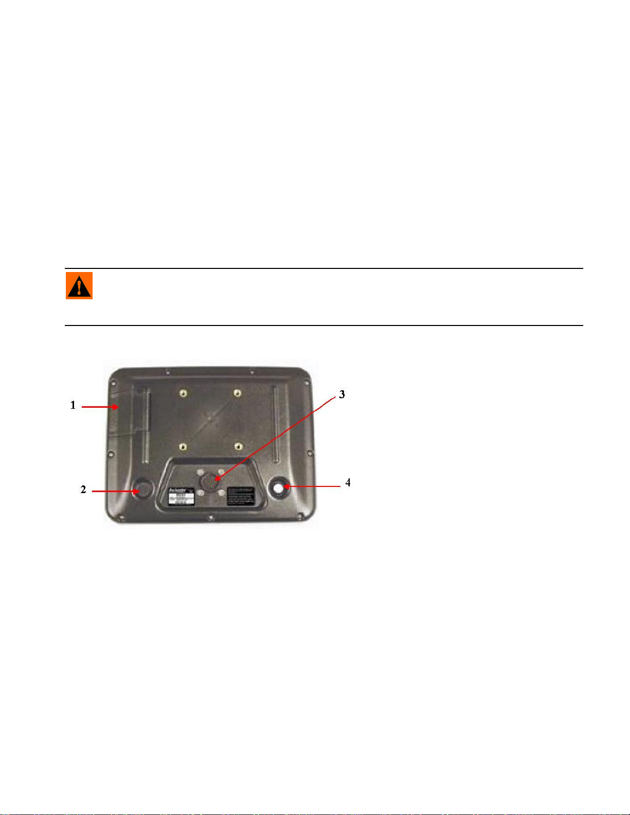
Display Hardware
GENERAL INFORMATION
Rear View of Display
1. Compact Flash Card Slot
The compact flash card slot has a sensor that
allows the display to know when the door is
open or closed. If the door is opened when a
card is in the display, an on-screen warning
will appear indicating when the card can
safely be removed. The display comes with a
compact flash card. The compact flash card
will be required to transfer files from the
display to a desktop computer.
2. Speaker
The built in speaker is used for audible
warnings. The speaker volume can be adjusted through the display setup routine.
3. 28-Pin Connector
The 28-Pin round connector contains CAN, RS-232 serial, and system power and ground connections.
4. Power/Reset Switch
The Power/Reset switch is used for turning the display on and off in installations where the system is
connected to a continuous power supply.
If the display ever stops responding, the manual power switch may be held in for five seconds to restart the
display. Only do this as a last resort, data loss could occur during times of improper shutdown.
5
Page 20
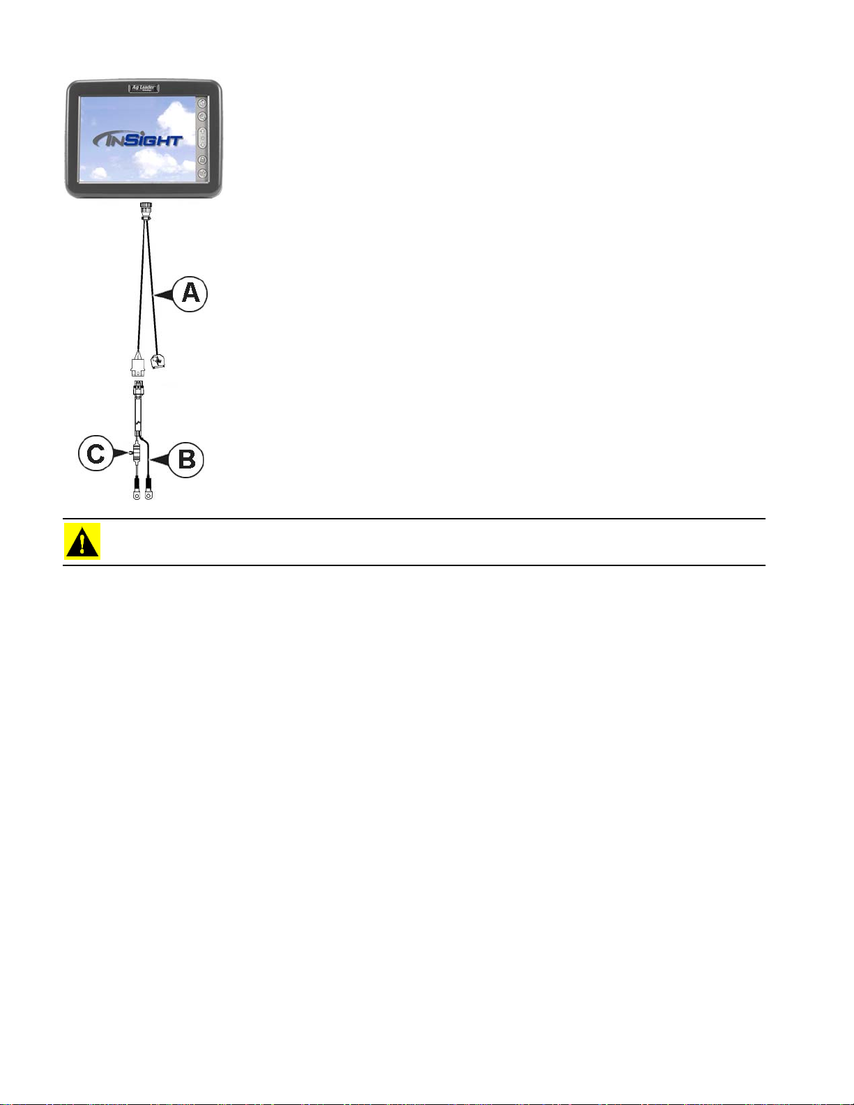
Fuse Installation and Replacement
a. 4000319-1
b. 2000452-4
c. Fuse Holder
Fuse Type: 3AG, 1/4 X 1-1/4., Fast Acting
Rating: 5A, 250 VAC
CAUTION: The fuse is to be placed in the fuse holder in-line with the battery power cable and used with the
display only.
POWER UP
The display comes with an AC power supply. Using the AC power supply, familiarize yourself with the
display features. We suggest taking the time to step through the initial configuration process with the aid
of this user guide prior to installing any of the display hardware in your equipment.
6
Page 21
SETUP
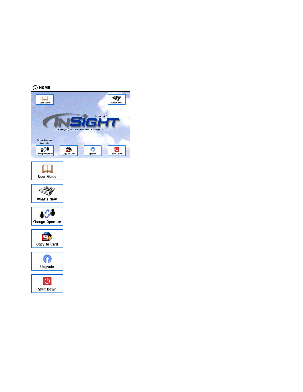
HOME SCREEN
The Home Screen will be shown each time the display is started. The table below describes the
functionality of each of the buttons present on the Home Screen.
Press to access the built-in user guide. Navigate the on-screen content using the forward
arrow, back arrow, and text hyperlinks.
SETUP
Press to access information on new products andfeatures.
Press to select a machine operator from the drop-down list. Machine operator information
will be logged with all field operations.
Press to copy all logged data files to the external storage card and remove from the
internal memory of the display.
Press to load program upgrade files from the external storage card.
Press to shut down the display.
7
Page 22
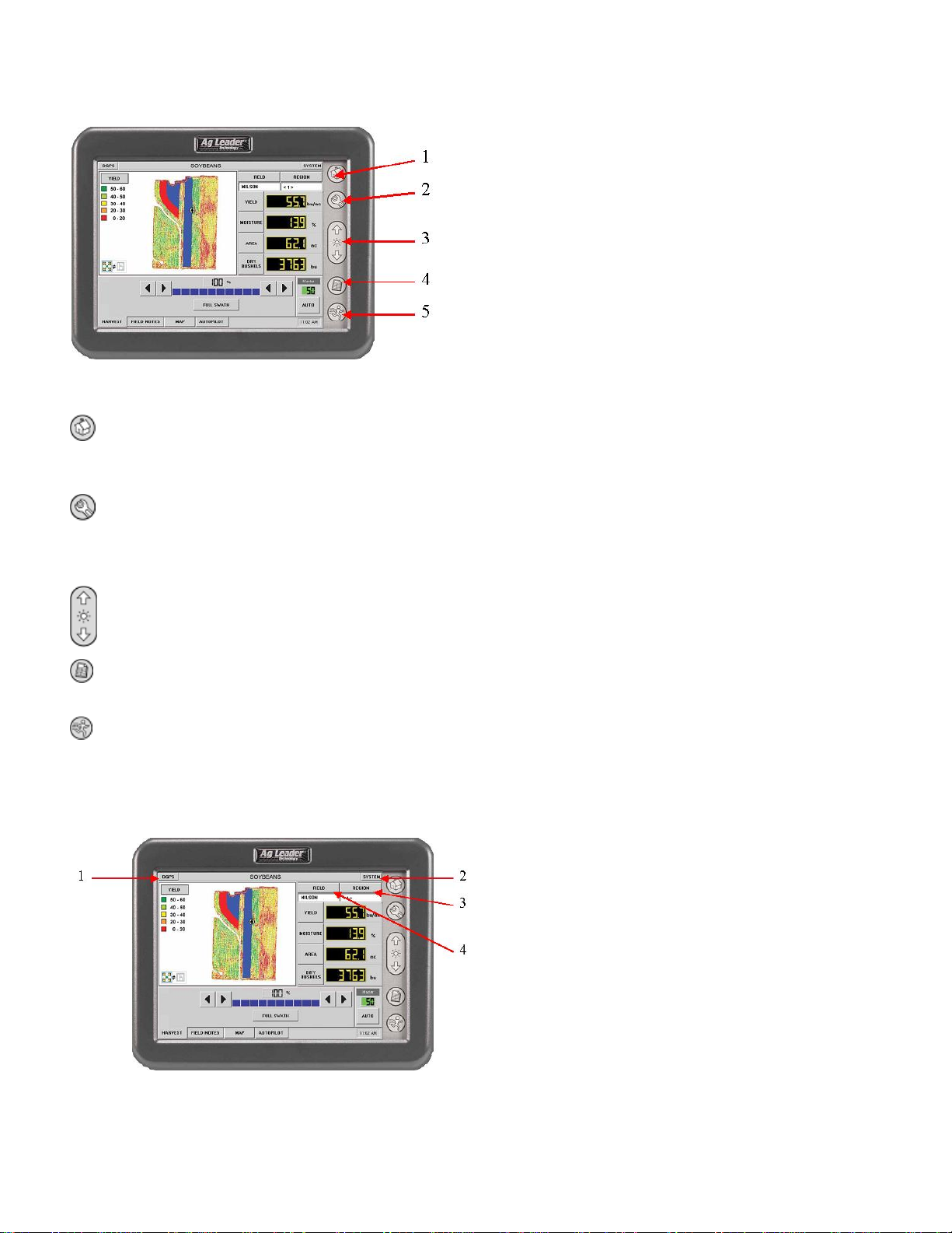
NAVIGATION BUTTONS
The display navigation buttons on the right edge of
the display are used to move between the different
areas within the display. The navigation button
functionality is consistent through out all different
modes of operation.
1. Home
Press to access the Home screen on the display. Options available at the Home screen are, Copy to Card,
Upgrade System, User Guide, Change Operator and Shut Down.
2. Setup
Press to access the menus and wizards used for display configuration. General setup item groups include,
Grower-Field Management, Field Notes, Display, and GPS configurations. Use specific setup item groups
include, Planting, Product Application, Tillage, and Harvest configurations.
3. Brightness
Press the Brightness Control to set display back light intensity to fit current operating conditions.
4. Summary
Press to display a summary screen showing totals for the current field operation you are performing.
5. Run
Press to launch the Run Screen. The Run Screen provides control of all field operations and the data logging
associated with, Harvest, Planting, Tillage, and Product Application.
RUN SCREEN COMMAND BUTTONS
Regardless of the current mode of operation,
these common buttons and the associated
functionality is always present at the run screen.
For more information on the Run Screen
command buttons, see
page 163.
“Run Screen Menu Tree” on
8
Page 23
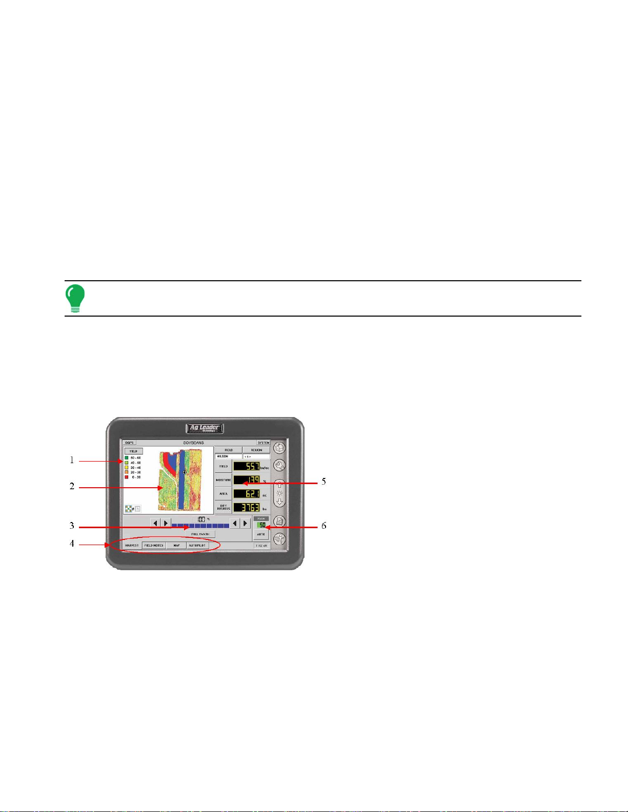
1. DGPS
Displays the quality of GPS signal in use by the display. If both differential and GPS signals are available,
this button will display DGPS. If GPS is available without differential correction, the button will display GPS.
If neither GPS or differential signal is available, two dashed lines (--) will be displayed on the button. Press
the DGPS button to display detailed GPS and differential correction information. For more information, see
“GPS Diagnostics” on page 49
2. SYSTEM
Press to launch information screens that include various tabbed pages for display of system operating
status. These pages include statistics on memory usage, diagnostics, and readings from various sensors
and system components connected to the display.
3. REGION
A region is used to subdivide a field into smaller sections. The region that is currently being logged to is
shown below the Region button. A new region can be created at any time as you are performing a field
operation. To change between or add a new region to a field, press the Region button and follow the on
screen instructions.
Note: Regions and Fields are created in the Run Screens’ Grower/Field Management Setup and are both
discussed in greater detail within each Operation section of this manual (such as Application, Tillage, etc.).
4. FIELD
The field that is currently being logged to is shown below the Field button. To change Fields, press the Field
button and select the desired field. The Operating Configuration and Product are also selected during this
process.
.
SETUP
RUN SCREEN DISPLAY AREA
The following tables describe the main features
and functionality of the Run screen. These
features remain constant between the different
modes of operation.
For more information on this Run Screen display
area, see
1. Legend
This area displays a choice of several legends appropriate to the type of field operation taking place. By
pressing the legend, a dialog is displayed that allows creating and saving custom legends.
2. Map Area
This area of the screen is dedicated to displaying the many different map objects available in the display.
Depending on the current field operation, one or more of the following different maps are made available.
• Field boundaries
• Crop yield and moisture
• Planter variety
• Field Notes marks
• Prescription maps
“Run Screen Menu Tree” on page 163.
9
Page 24
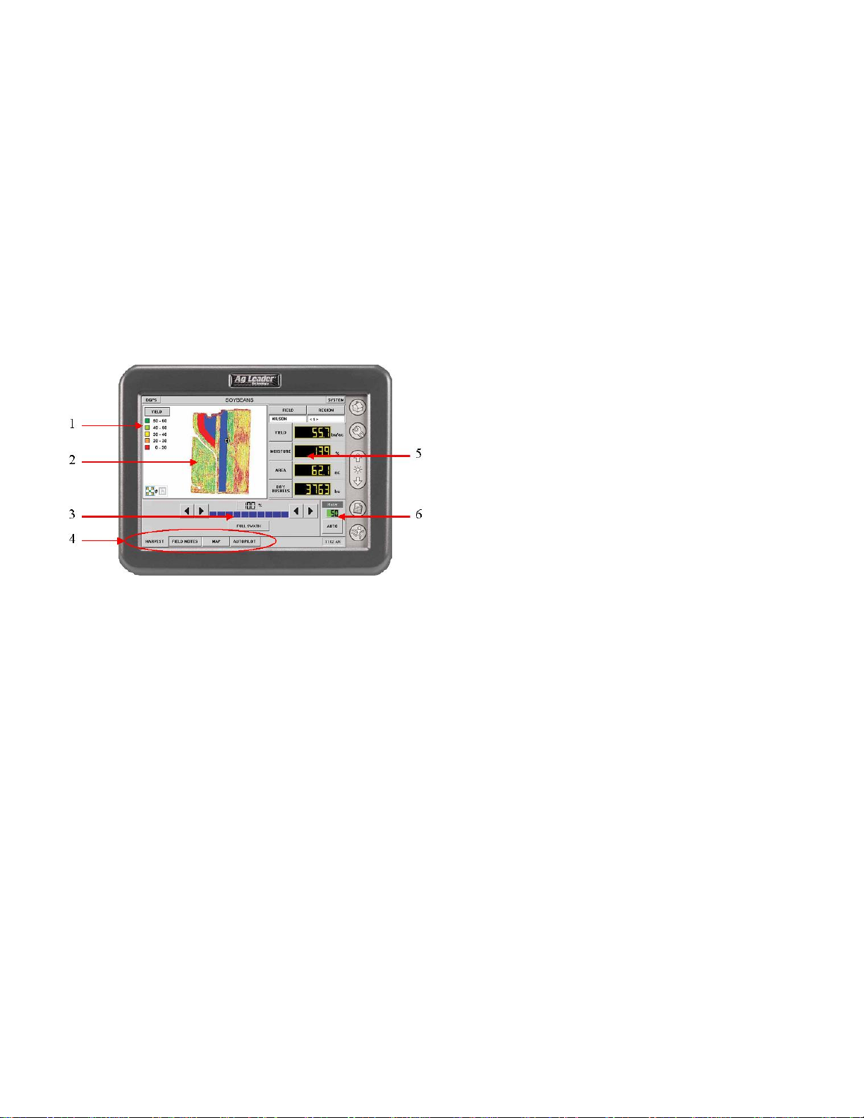
• Applied rate maps
• Product coverage maps
• Reference map
3. Swath Bar
This area of the Run Screen displays the current swath being harvested or applied. When operating in
Harvest mode, as shown in the figure above, width can be modified from the left or right to match the swath
width that is actually being harvested. When operating in Application Rate mode, this area will display
individual boom sections and their current status.
4. Control Tabs
Each Control Tab contains content specific to the current mode of operation. Examples of the various tabs
functionality include using the Field Notes feature, viewing and setting product control parameters, and
interaction with Ag Leader lightbars and Autopilot navigation controllers.
DISPLAY ITEMS AND AREA COUNT
5. Run Screen Display Items
This area of the screen displays the user's choice of
four different data items. The type of field operation
being performed determines what items are available
for selection. Any of the four display items can be
changed by pressing on that item and choosing a
different data item from a pop up list that is shown on
the display screen.
Examples of the different items made available are:
• Harvest:
• Yield
• Moisture
• Area
• Application Rate:
• Applied rate
• Applied area
• Total applied
6. Area Count Status
This button will be present when appropriate during harvest, planting, tillage operations and any other time data
is being logged to the display without controlling application rate. The button functions as a master area count
on/off switch. Area count can be turned on/off manually by pressing the button or will turn on/off automatically
when a header or implement switch is being used with the current operating configuration.
10
Page 25
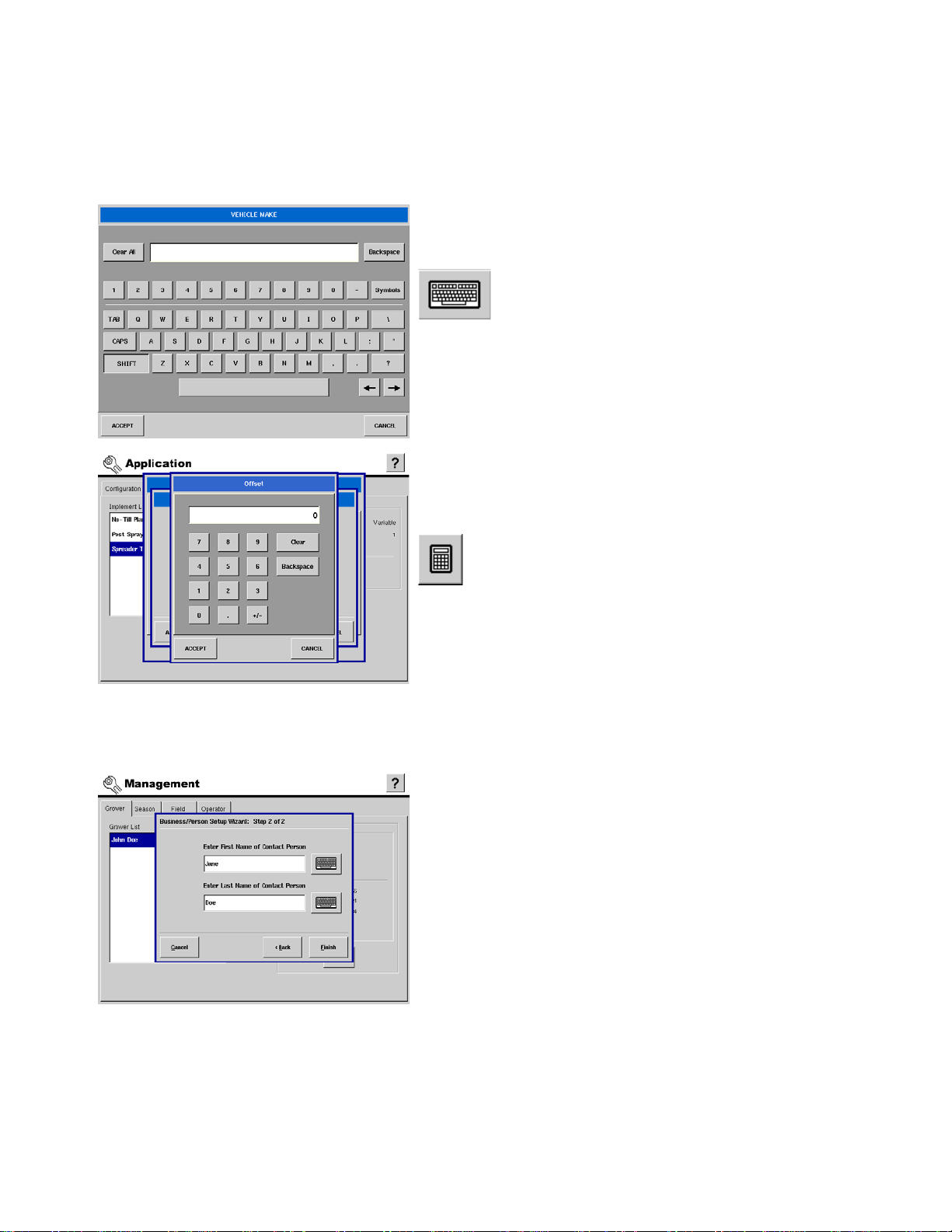
GETTING STARTED
Entering Data Into the Display
The following control buttons are made available for entering names and calibration values into the
display.
An on-screen Keyboard is made available when appropriate
for use during all setup processes. Press the keyboard button
to access the on-screen text entry screen shown at the right.
An on-screen Numeric Keypad is made available for
changing configuration settings and calibration numbers.
Press the keypad button to access the on-screen numeric
entry screen shown at the right.
SETUP
SETUP TIPS
Setup Wizard Use
Most configuration of the display is accomplished by using
setup wizards. Setup wizards are a series of on-screen
dialogs that move the user through the configuration process
in a simple to follow step-by-step manner.
11
Page 26
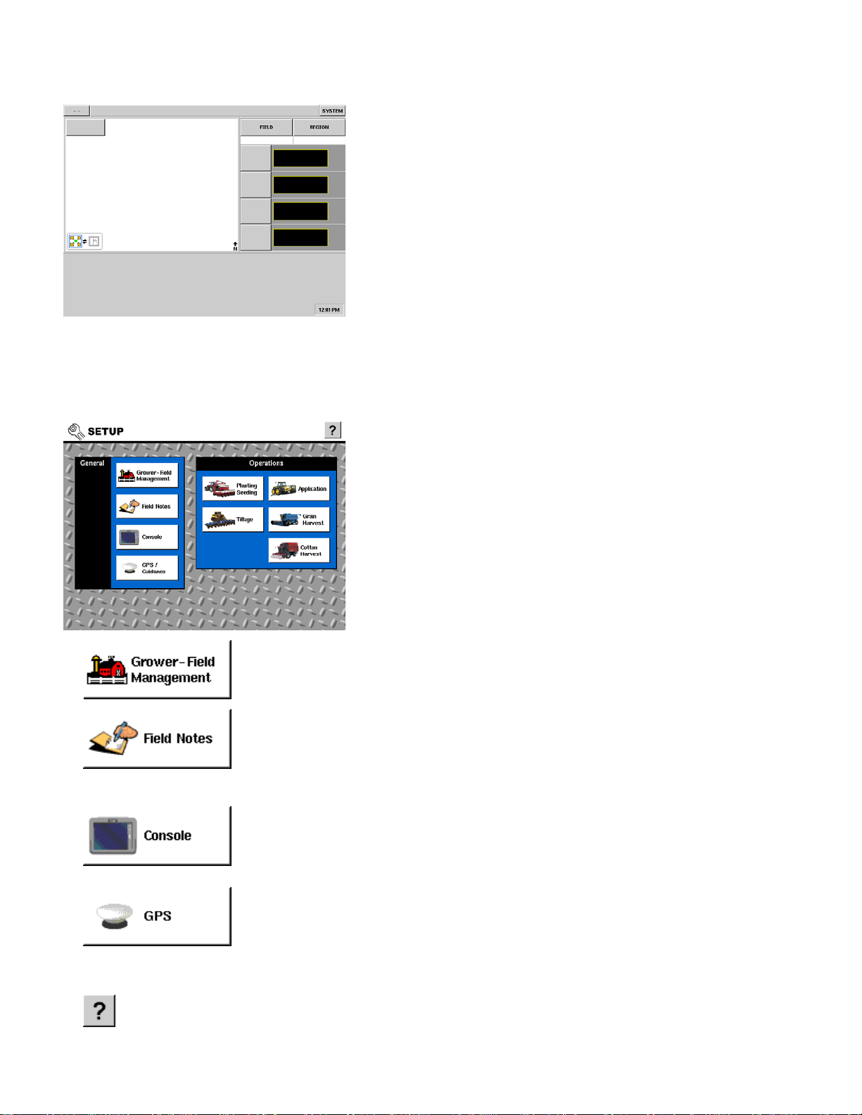
Functionality
GENERAL SETUP
GENERAL SETUP OVERVIEW
Much of the functionality of the display is not available at the
Run Screen until the basic setup process is completed. Prior
to initial setup the Run Screen will look like the following
figure. Other than the information available under the DGPS
(--) and SYSTEM buttons no functionality will be present.
Required initial configuration steps include the following:
• Grower/Field Management Setup
• Equipment Operating Configuration Setup
• Product Setup
This section of the User Guide covers the setup items and
processes that are common to all operations within the
display. All setup screens and wizards are made available by
pressing on each of the buttons on the General Setup section
of the display. Below is a description of the basic functionality
of each of the main control buttons, with cross references to
more descriptive information.
Press to access the Management screen where Grower, Season, Field, and Machine
Operator are set up and edited. For more information, see “Grower And Field
Management Setup” on page 13.
Press to access the Field Notes function setup. Field Notes are tools that allow
marking points and logging data to those points while performing any field operations
while in the run screen. Settings related to automating product application reporting
are also contained in Field Notes setup. For more information, see “Field Setup” on
page 18; as well as “Field Notes Setup Screen” on page 22 and “Using Field Notes” on page 33.
Provides access to setting date/time, unit of measure settings, display owner
information setup, unlocking any optional features purchased with the display, as well
as some basic memory and storage card maintenance functionality. For more
9
information, see “Display Setup” on page 26.
Press to configure Ag Leader Technology TSIP GPS receivers, lightbars and Autopilot
systems. For detailed information, see “GPS General Setup Tab” on page 37 and
“Autopilot Setup” on page 54.
ON SCREEN HELP
On screen help is made available by pressing the Help button in the upper right corner of the screen.
12
Page 27
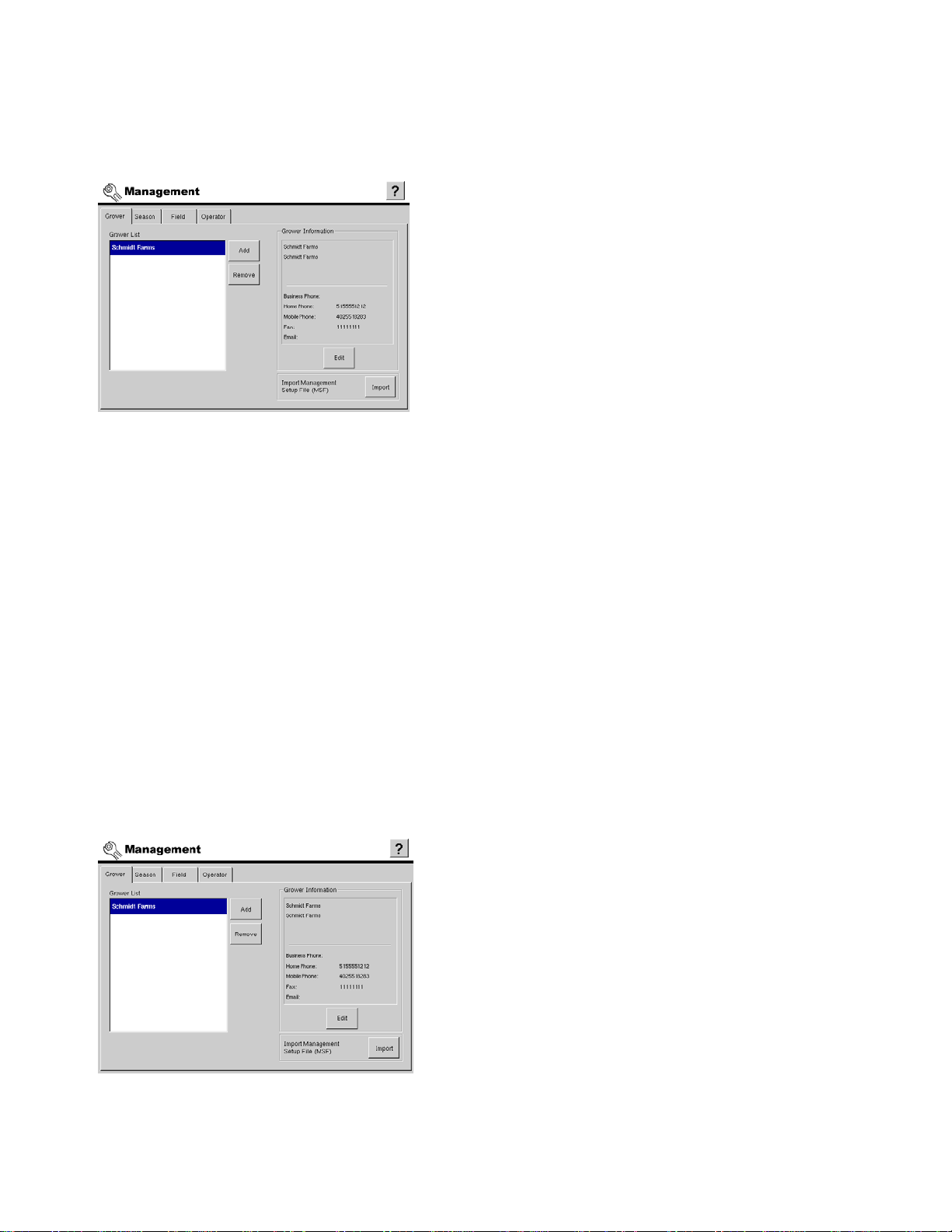
GROWER AND FIELD MANAGEMENT SETUP
FIELD OPERATION DATA STORAGE
All data is stored in a hierarchical data structure for use within
the display and desktop GIS software packages. As needed,
the on-screen keyboard is made available for typing when
performing actions like naming Growers and Fields.
• Grower
The Grower tab is used to set up the businesses or people that own one or more farms. For more
information, see
• Season
The Season Tab is used to set up the crop season. The season is defined as the calendar year that the
crop, relating to the current field operation, will be harvested. For more information, see
Screen” on page 14
“Grower Setup Screen” on page 13
.
.
“Season Setup
SETUP
• Field
The Field Tab is used to set up fields and all descriptive information relating to them. For more information,
see
“Field Setup Screen” on page 18
• Operator
The Operator Tab is used to set up machine operator and Certified Custom Applicator license information.
For more information, see
“Operator Setup Screen” on page 20
.
.
SEASON SETUP
GROWER SETUP SCREEN
The Grower is a global setting that refers to the business or
person that the display is in operation for.
Contact information can also be entered for each Grower.
The Grower information will be passed into mapping
software for automatic Grower setup within desktop software.
• Grower List
Displays all Growers configured within the display.
13
Page 28
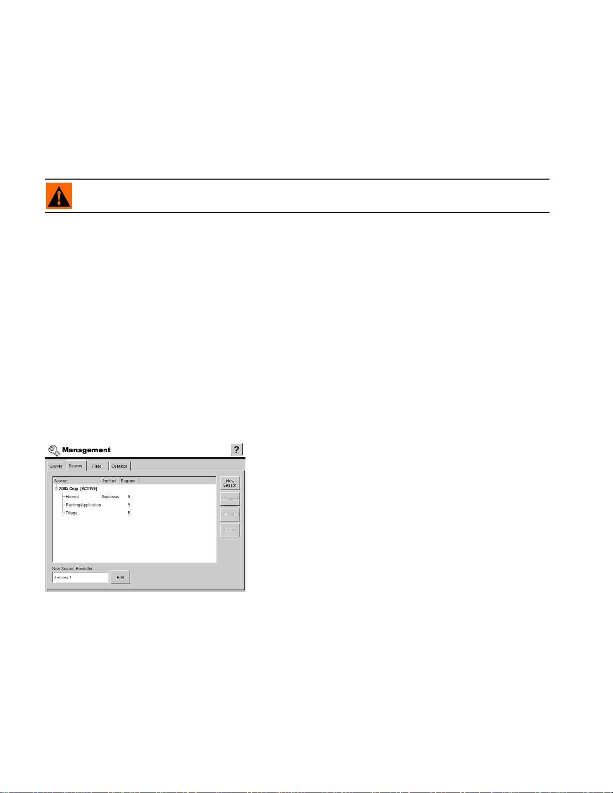
• Add button
Press to launch the software wizard used to create a new grower. For more information, see
Grower” on page 15
• Remove button
Press to remove a selected entry in the Grower list.
When the Remove button is pressed the following warning will be presented allowing the user to cancel the
remove process if desired.
WARNING: When removing a grower all data in the fields and regions relating to that grower
are also removed!
• Grower Information
This region of the screen displays all the optional information that is stored for a specific Grower.
• Edit button
Press to access a data entry screen for adding or editing the optional Grower information. For more
information, see
• Management Setup File (MSF)
Displays the Import button used for .MSF files.
.
“Adding or Editing Grower Personal Information” on page 16
.
“Adding A New
• Import button
Press to import a Management Setup File (.MSF) of Grower, Farm and Field information exported from
desktop software and stored on your Compact Flash Card. For more information, see
Management Setup File” on page 16
.
“Importing A
SEASON SETUP SCREEN
A season is defined as the calendar year that the crop will be
harvested. Creating a season and setting it to active is
required prior to the display logging any data.
• Summary list box
Displays a list of all seasons set up in the display.
• New Season
Press to create a new season. When a new season is created, it is set to active by default. No data will be
logged to any inactive seasons that are present in the display.
• Edit Name
Press to edit the name of the season currently selected in the summary list box.
• Set Active
14
Page 29
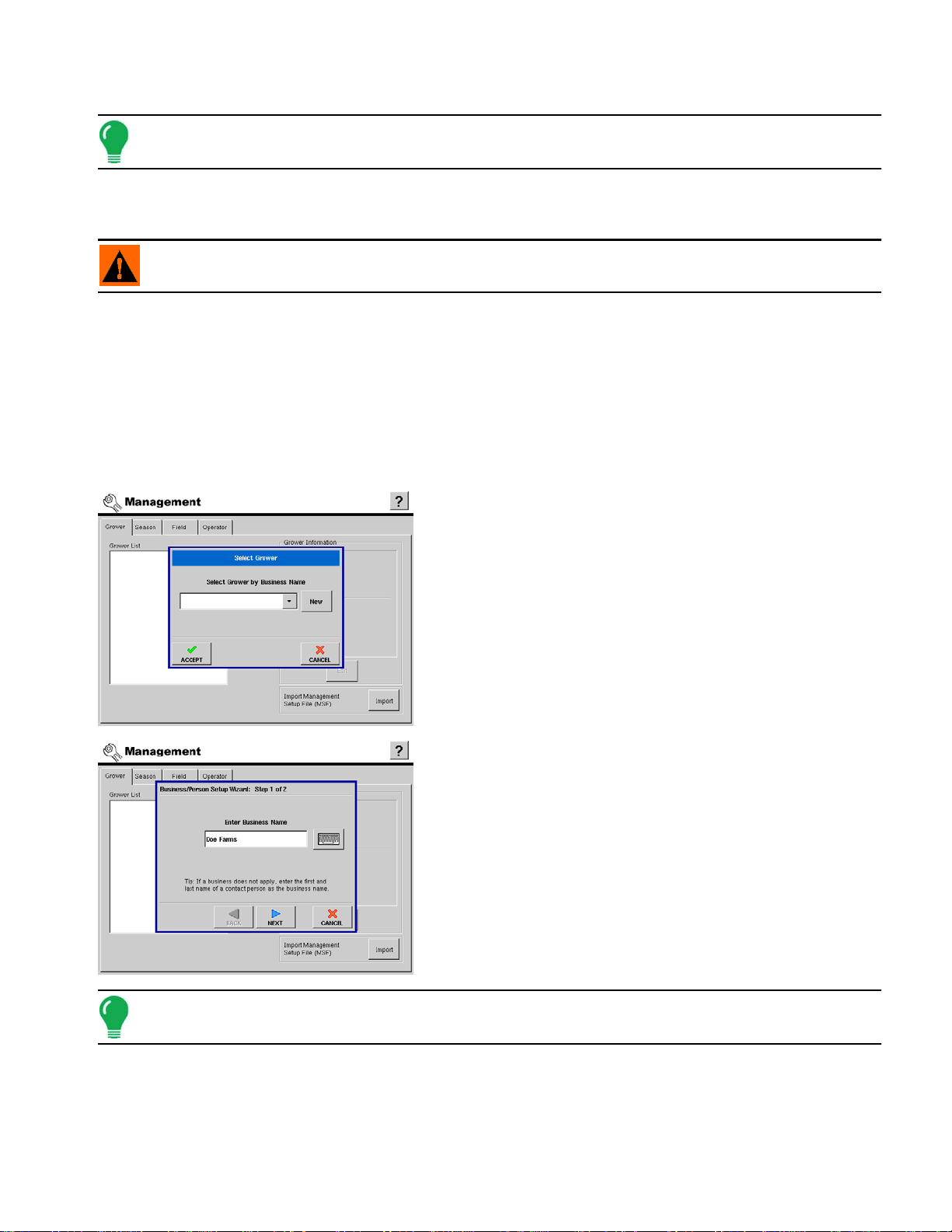
Press to set the season selected in the Summary list box to the active season.
Note: All data is logged to the active season.
• Remove
Press to remove the season that is currently selected in the Summary list box.
WARNING: All the data pertaining to operations, regions, and maps for a season will be removed when the
season is removed.
• New Season Reminder
Press to set the date that the display will prompt the user to create a new season.
GROWER SETUP
ADDING A NEW GROWER
The following screen shots represent the steps involved with setting up a new Grower.
1. Select Grower
After pressing the Add button on the Grower screen, the Select
Grower dialog is shown. The drop down list box displays all
businesses within the display and makes them available for
selection as a Grower. If the Grower is not present in the display
as a business contact or machine operator, press the New button
to start the process of adding new grower information.
SETUP
2. Business/Person Setup
Because in most cases Growers are Business or Farm owners,
the first step of the setup process asks that a Business Name be
entered into the display. On the rare occasion that the grower is
neither a business or farm owner, it is recommended that the
person's first and last name be entered as a Business Name.
After entering the Business Name into the display, press Next
to proceed to the final step in the setup process.
Note: If you are using desktop software, it is recommended that you use the same names as in the software.
15
Page 30
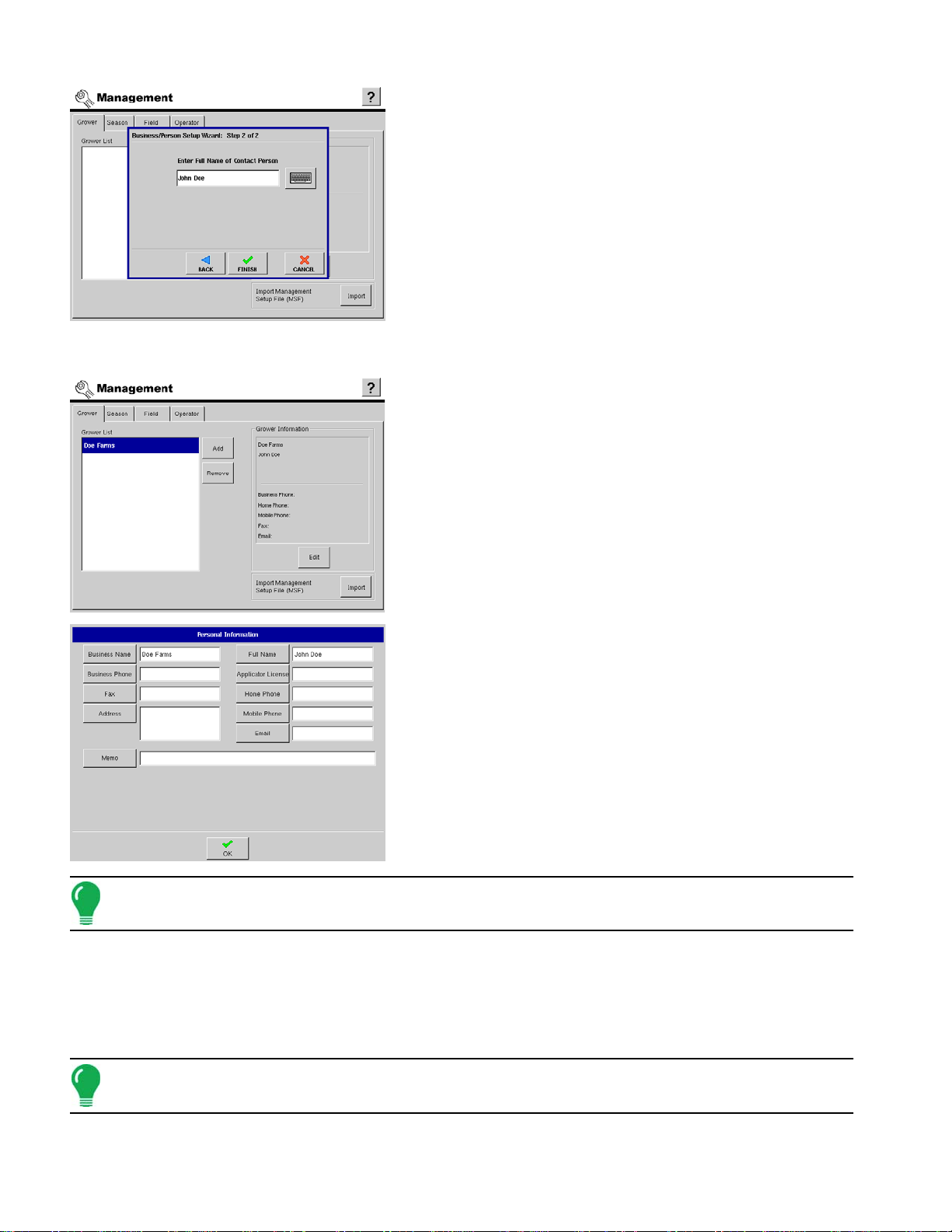
3. Business/Person Setup
Enter the first and last name to be used as a contact for the
Grower information then press Finish to complete the new
Grower setup process.
ADDING OR EDITING GROWER PERSONAL INFORMATION
1. Accessing the Edit Screen
Select a Grower from the Grower List and press the Edit button
to enter or edit any of the data displayed in the Grower
Information frame.
2. Personal Information Data Entry
After pressing the desired control button, the on-screen keyboard
or numeric keypad will show to allow data entry into the display.
Press OK to complete the process.
Note: Information on the screen can be added or edited at any time.
IMPORTING A MANAGEMENT SETUP FILE
A Management Setup File (.msf) is a file format that allows the display to import Grower and Field
information from desktop software via a Compact Flash Card. Follow the process outlined below to
import desktop software information from your Compact Flash Card.
Note: When importing management items from an .MSF setup file, the imported data will always update or
be added to existing management data and will not overwrite it.
16
Page 31

1. Press the Import button
Press the Import button on the Grower tab of the Management
screen. (Be sure that your Compact Flash Card is already placed
in the display).
2. Locate your file on the Compact Flash Card
The File Selection Screen appears. The folder titled "Ag Leader
Technology SMS" contains your .MSF files. Open this folder by
pressing the Plus (+) sign to the left of the folder.
SETUP
3. Accept the .MSF file
Press the .MSF file to highlight it. A blue bar highlights your
selected .MSF file, as shown at left. Press the Accept button to
import this file.
4. Display shows information from .MSF
The Grower information now appears in the Grower tab of the
Management screen. In the example at left, information for Smith
Farms now appears on the Management screen.
17
Page 32

FIELD SETUP
FIELD SETUP SCREEN
A field consists of one or more outer boundaries. Each outer
boundary can contain one or more inner boundaries used to
define any combination of roadways, waterways, building
sites, or bodies of water. If the display will be used for multiple
Growers, enter each Grower business name and associate
the field names with the correct grower when the fields are
setup within the display.
Select Grower
Used to select which grower's fields to display in the Farm/Field list.
Farm / Field List
Displays a list of all farms and fields associated with the selected
grower.
• Add
Press to launch the new field creation wizard. For more information, see
• Edit Name
Press to edit the name of the item selected in the Farm/Field list.
• Remove
Press to remove the item selected in the Farm/Field list.
“Adding a New Field” on page 19
.
WARNING: When a field is removed, all data for that field will be removed!
Information Frame
When a farm is selected in the Farm/Field list, the grower name
is displayed in this frame. When a field is selected in the
Farm/Field list, all descriptive text for legal description and field
geographic location is displayed in this frame.
• Edit
Press to summon the Field Information window, where you
can add or edit any of the information stored for the field
selected in the Farm/Field list. For more information, see
Information” on page 19
.
“Field
Boundary Frame
When a field is selected in the Farm/Field list any collected boundaries and total area will be displayed in this
frame. For more information on creating field boundaries, see “Field Boundary Creation” on page 36.
• Import
Press to import a field boundary from the external storage card. For more information, see
Exporting Boundaries” on page 20
• Export
Press to export a selected field boundary to the external storage card. For more information, see
/ Exporting Boundaries” on page 20
.
.
“Importing /
“Importing
18
• Clear
Page 33

Press to delete a field boundary from the display.
WARNING: All inner and outer boundaries associated with a field will be deleted from the display when
clearing a boundary.
Field Information
Pressing the Edit button underneath the Edit portion of the Field
Tab summons the Field Information window, as shown. Here
you can enter or edit field information and the legal description
of that field; clear the Map Bounds; and choose or enter a new
Farm with the Farm Setup Wizard.
Note: Pressing the Clear Bounds button centers the map on the current GPS position. This is particularly
useful if you have flyer points or have logged a point outside the mappable range of your current location.
SETUP
ADDING A NEW FIELD
1. Select Farm
Use the drop down list to choose the correct Farm. To enter a new
Farm name press the New button and use the on-screen
keyboard to enter in a name.
Press NEXT to continue.
2. Add Field Name
Use the New button to enter the new Field name. More than one
field can be created at this time.
Press FINISH to complete the setup process.
19
Page 34

IMPORTING / EXPORTING BOUNDARIES
Field Boundaries
Boundaries can be created with the display or imported from desktop GIS software. Any boundary files
present in the display can also be exported for use in desktop mapping software.
• Boundary Import
To import a boundary from the external data card, highlight the
correct field in the Farm/Field list.
Press Import, select the desired file.
Press Accept to complete the import process.
• Boundary Export
If you would like to export a boundary to the external data card
highlight the correct field in the Farm/Field list. Then press the
export button. A window will appear telling you that the boundary
was exported successfully.
OPERATOR SETUP
OPERATOR SETUP SCREEN
Press OK to return to the field setup screen.
A machine operator must be selected at initial startup of the
display and can be changed as needed from the Home
screen.
Operator List
Displays a list of all machine operators configured within the
display.
• Add
Press to add a new machine operator. The first and last name of any people entered into the display as
contact information for a business or grower will be made available for selection from a list. New people can
be added to the display by following the setup wizard steps. For more information, see
Operator” on page 21
20
.
“Adding A New
Page 35

• Remove
Press this button to remove the selected entry from the Operator List.
• Operator Information Frame
Displays all information stored within the display for the selected entry in the Operator List.
• Edit
Press to edit any information stored for a selected operator. For more information, see
Operator Personal Information” on page 22
.
ADDING A NEW OPERATOR
New Operators are added to the display by following the simple process outlined below.
1. Business/Person Setup
After pressing the Add button on the Operator screen, the Select
Operator dialog is shown. The drop down list box displays all
people setup within the display and makes them available for
selection as an Operator.
If the Operator is not present in the display as a business or farm
contact, press the New button to start the process of adding
Operator information.
SETUP
“Adding or Editing
2. Business/Person Setup
Because Operators are directly related to a Business or Farm
owner, the first step of the setup process asks that a Business
Name be entered into the display.
After entering the Business Name into the display, press Next to
proceed to the final step in the setup process.
Note: For situations where the Operator is not the primary owner of an existing business or farm, it is
recommended that the person's first and last name be entered as a Business Name.
3. Business/Person Setup
Enter the first and last name for the Operator and press Finish to
complete the new Operator setup process.
21
Page 36
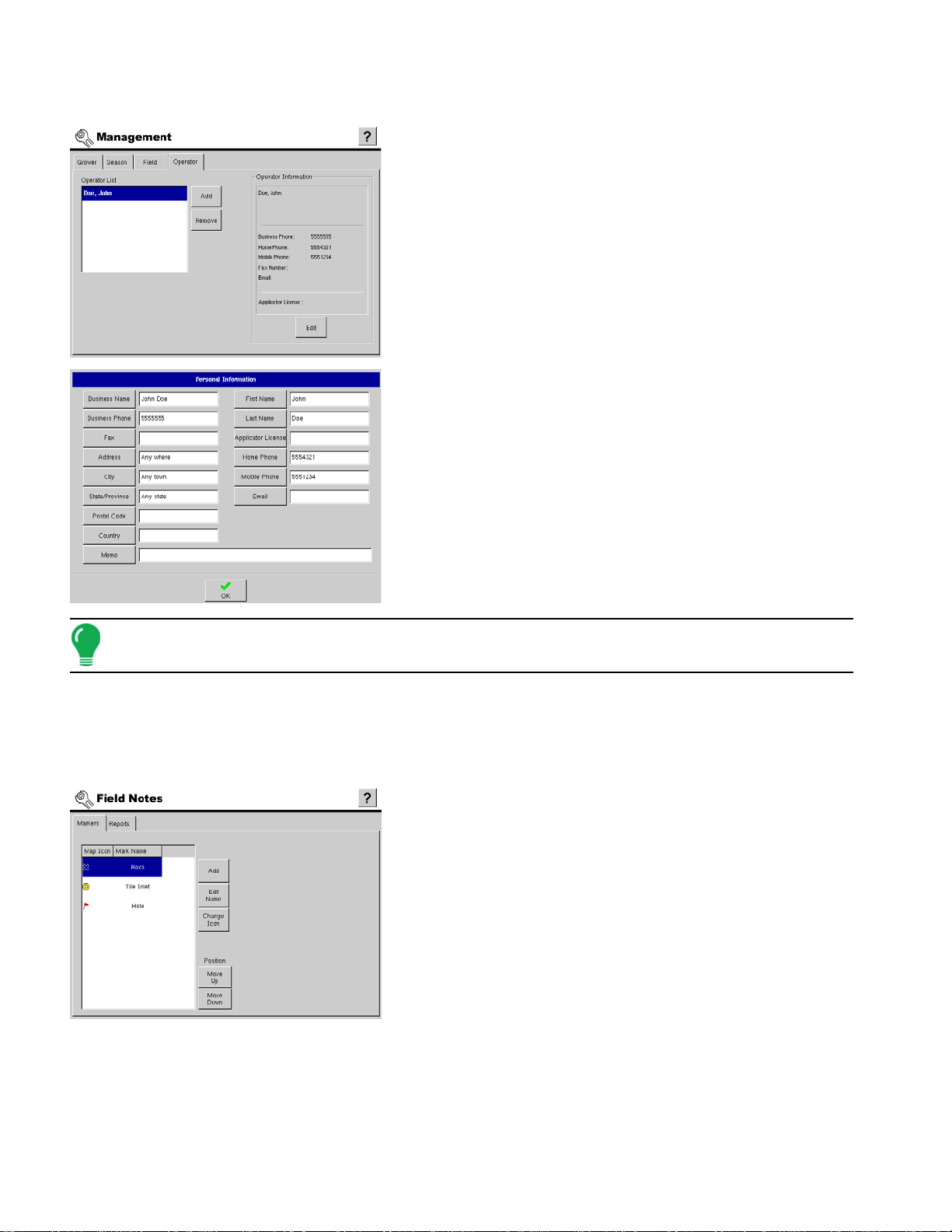
ADDING OR EDITING OPERATOR PERSONAL INFORMATION
1. Accessing the Edit Screen
Select an Operator from the Operator List and press the Edit
button to enter or edit any of the data displayed in the Operator
Information frame.
2. Personal Information Data Entry
After pressing the desired control button, the on-screen keyboard
or numeric keypad will be shown to allow data entry into the
display. Press OK to complete the edit process.
Note: Information on the screen can be added or edited at any time.
FIELD NOTES CONFIGURATION
FIELD NOTES SETUP SCREEN
Markers are a collection of point objects that are available on
the Field Notes tab of the run screen. As the name suggests,
markers allow mapping points on the go to identify specific
features within a field.
Displays all Markers and the icon in use for each Marker.
• Add
Press to display the keyboard screen to create and name a new marker. For more information, see
“Creating a New Marker” on page 23
.
• Edit Name
22
Page 37

Press to display the keyboard screen to edit the name of any selected marker. For more information, see
“Editing A Marker Name” on page 24
• Change Icon
Press to change the icon of any selected marker. For more information, see
page 25
• Move Up
Press to move a selected marker up one position in the markers list. This also changes the order in which
the Markers are displayed on the Run Screen.
• Move Down
Press to move a selected marker down one position in the markers list. This also changes the order in which
the Markers are displayed on the Run Screen.
• Reports Tabs items
The settings and options contained on the Reports tab of the Field Notes configuration settings determine
the behavior of the display at the Run Screen during the process of creating application reports. For more
information, see
.
“Application Reporting” on page 244
.
“Changing A Marker Icon” on
.
CREATING A NEW MARKER
The steps below outline the process of setting up Markers within the display.
No Markers
SETUP
Field Notes screen prior to any markers being configured.
Adding A Marker
Press the
launch the on screen keyboard. Enter any combination of
letters, numbers, and symbols up to 10 characters long to be
used as the name for the new Marker. Press the
button to finish adding the Marker to the display.
ADD button on the Field Notes setup screen to
ACCEPT
23
Page 38

EDITING A MARKER NAME
Field Notes setup screen after adding a Marker named Rock.
The process of renaming a Field Notes Marker is outlined in
the steps below.
Existing Marker Name
Field Notes screen with an existing Marker named Rock.
Select Rock from the list box and press the
to rename the Marker.
EDIT NAME button
Enter the new name for the existing Marker, press
save the change.
Field Notes screen with Marker renamed to Boulder.
ACCEPT to
24
Page 39

CHANGING A MARKER ICON
is the default icon assigned by the display for all new Markers. A different icon can be assigned to a
Marker by following the steps outlined below.
Select Marker To Edit
To change the icon for a Marker, select the desired Marker
from the list and press the
CHANGE ICON button.
SETUP
Select the desired icon from the list and press
save the change.
Field Notes setup after changing the rock icon.
ACCEPT to
25
Page 40

DISPLAY SETUP
GENERAL DISPLAY SETUP TAB
The General Tab contains settings related to time, date, and
display Owner information.
• Date
Press to set current date.
• Time
Press to set current time.
• Time Zone
Select the correct time zone for your area from the drop down list box.
• Operating Units
Select between using Imperial or Metric units for calibration and control units.
• Speaker Volume
Press the arrows to set the volume of on-board speaker.
• Calibrate Touchscreen
Press to launch the touch screen calibration wizard. For more information on calibrating the touch screen,
see
“Touch Screen Calibration” on page 26
• Display Owner
This area of the display contains functionality for setting up a Display Owner and making any needed edits
to the owner personal information. The Display Owner information is used in the product application report
feature of application rate control. An image for the Display Owner can be imported for inclusion on product
application reports. For more information on the Display Owner Setup, see
page 27
.
.
“Display Owner Setup” on
TOUCH SCREEN CALIBRATION
Do not use any sharp objects to operate the touch screen or the display may be damaged.
Confirm Touchscreen Calibration
26
Page 41

Press YES to confirm the start of the touchscreen calibration
process.
Calibration Wizard
Calibrate the touchscreen following the on-screen
instructions.
SETUP
DISPLAY OWNER SETUP
Image Import” on page 27
• Clear Image
Press to delete the Business Owner image.
.
• Select Owner
Press to display a list of all farm and business contacts set up
in the display. The on-screen dialog that is displayed will give
option to select an existing person/business or create a new
one to be used as the Display Owner.
• Edit Info
Press this button to edit or add the personal information for
the Display Owner.
• Import Image
Press to import the image file that is displayed with the
Display Owner information on any application reports that are
created. The display currently supports .bmp and .png file
formats. Size is limited to a maximum of 200 pixels wide x
100 pixels tall. For more information, see
“Display Owner
Display Owner Image Import
Follow the steps outlined below to import a Display Owner image.
Before Image Import
27
Page 42

Display General setup screen prior to a Display Owner image
being imported.
Image File Selection
After pressing the
Import Image button the dialog at the left is
displayed to allow the selection of a file to import. Press the
ACCEPT button to import the selected file.
After Image Import
Display General setup screen after importing a Display
Owner image.
28
Page 43

DISPLAY SETUP MEMORY TAB
Card Management Features
• Delete File
Press to delete a selected file from the external
memory card.
• Create Backup File
Press to create a backup file of all configuration
settings, products, and Grower-Field Management
data structure on the external memory card. Backup
files are stored using the .ibk file format.
• Restore from Backup
Press to restore a backup file from the external data
card to the internal memory of the display.
• Copy All Log Files
Press to copy all logged data to the external memory
card. Log files are stored using the .ilf file format.
• Clear Internal Memory
Press this button to clear the internal memory of the display. The display will present a warning dialog box
and ask if you would like to create a backup file prior to clearing the memory.
SETUP
CAUTION: The display will be returned to “new out of box” unconfigured state when the memory is cleared.
DISPLAY FEATURES
Enabling Display Features
Unlocking Features
Unlock codes are unique to the serial number of each display
and the feature registration number. You must supply these
numbers to your Ag Leader dealer when purchasing any
unlock codes. Use the on-screen keyboard to enter the
unlock code and press ACCEPT to enable the feature.
Note: Once a feature is unlocked, that feature remains with that display and cannot be transferred to another.
29
Page 44

ADVANCED
WARNING: The Advanced Parameters, Copy Error Logs, and Guidance Debug Files functionality on the
Advanced tab is reserved for use by Ag Leader Engineering. DO NOT change any of these settings without
specific instruction from Ag Leader Technology.
OPERATIONS SETUP
Advanced Display Settings
The Advanced Tab contains the following functions of interest to
most users:
• Copy Log Files to Memory Card at Shutdown - Checking this
check box will copy all log files to the external memory card when
the monitor is turned off.
OPERATIONS SETUP BASICS
30
Press to access setup of planter logging, mapping, and population control
configurations. For more information, see “Planting And Seeding Setup” on page 31.
Press to access setup of tillage operation mapping configurations. For more
information, see “Tillage Operation Setup” on page 31.
Press to access setup of product application logging, mapping, and rate control
configurations. “Application Setup” on page 32.
Press to access setup of Grain Harvest yield monitoring configurations. For more
information, see “Grain Harvest Yield Monitoring Setup” on page 32.
Press to access setup of Cotton Harvest yield monitoring configurations. For more
information, see “Cotton Harvest Yield Monitoring Setup” on page 33
Page 45

PLANTING AND SEEDING SETUP
The Planting setup screens contain all the necessary settings
to configure the display for logging, mapping, and population
control of all supported planting operations. For more
information, see
• Configuration
Add and edit operating configurations. Operating configurations are a combination of Vehicle, Implement,
and Controller.
Configuration examples:
- Tractor and planter mapping seed varieties.
- Tractor and planter using seed population control.
• Vehicle
Add and edit vehicle configurations. Settings include GPS offsets of rear axle and implement mounts in
relation to GPS antenna.
“Planting Setup Tabs” on page 89.
SETUP
• Implement
Add and edit implement configurations. Settings include locations for product dispense and swath locations
in relation to GPS antenna and vehicle hitch.
• Controller
Add and edit product population rate control channels.
• Product
Add and edit seed type and varieties.
TILLAGE OPERATION SETUP
The Tillage setup screens contain all the necessary settings
to configure the display for mapping tillage operations. For
more information, see
• Configuration
Add and edit operating configurations. Operating configurations
are a combination of Vehicle, and Implement.
Configuration examples:
• Tractor with pull-type field cultivator.
• Tractor with mounted cultivator.
• Tractor with mounted chisel plow.
“Tillage Setup Tabs” on page 75 .
• Vehicle
Add and edit vehicle configurations. Settings include GPS offsets of rear axle and implement mounts in
relation to GPS antenna.
• Implement
31
Page 46

Add and edit implement configurations. Settings include locations for tillage point in relation to GPS antenna
and vehicle hitch.
APPLICATION SETUP
The Application setup pages contain all the necessary
settings to configure the display for logging, mapping, and
rate control of supported methods of product application. For
more information, see
• Configuration
Add and edit operating configurations. Operating configurations
are a combination of Vehicle, Implement, and Controller(s).
Configuration examples:
• Self propelled sprayer with PWM valve rate control.
• Pull-Type sprayer with servo valve rate control.
• Single product self-propelled fertilizer spreader with hydraulic
servo valve control.
• Vehicle
Add and edit vehicle configurations. Settings include GPS offsets of rear axle and implement mounts in
relation to GPS antenna.
• Implement
Add and edit implement configurations. Settings include product dispense and swath locations in relation
to GPS antenna and vehicle hitch.
“Application Setup Tabs” on page 167.
• Controller
Add and edit product control channels. Settings include product control valve and response threshold
values.
• Product
Add and edit crop nutrient and protection products. Allows configuration of fertilizer blends and tank mixes.
GRAIN HARVEST YIELD MONITORING SETUP
The Grain Harvest setup screens contain all the
necessary settings for configuration of yield monitoring
operations. For more information, see
Setup Tabs” on page 281.
• Configuration
Add and edit operating configurations. Operating
configurations are a combination of Combine and Header.
• Combine
Add Combines from a list of all supported platforms.
• Header
Add and edit row, pickup, and platform style headers.
Settings include platform width and header lift switch
configuration.
“Grain Harvest
• Crops
Add and edit crop type and varieties.
32
Page 47

• Calibration
Provides access to all calibration settings related to an operating configuration.
COTTON HARVEST YIELD MONITORING SETUP
The Cotton Harvest setup screens contain all the
necessary settings for configuration of yield monitoring
operations. For more information, see the Cotton
Harvest Insert (Ag Leader Part No. 2002881).
• Configuration
Add and edit operating configurations. Operating
configurations are a combination of picker and head type.
• Picker
Add pickers from a list of all supported platforms.
• Crop
Add and edit crop and varieties.
• Calibration
Provides access to all calibration settings related to an operating configuration.
SETUP
RUN SCREEN GENERAL TABS
FIELD NOTES TAB
When an active configuration is selected at the Run Screen,
the Field Notes and related functionality will be present.
MARKERS
Press the Note button to launch an on-screen dialog that allows attaching a text memo to the
current field location.
Multiple text memo items can be created in each field.
USER DEFINED MARKERS
Press to add a point in the field with the desired attribute. The
use of these markers are described further in
on page 33.
Press the Fill Empty button to access the container fill events dialog. This functionality is only
used during liquid product application. For more details, see
the Application section.
“Using Field Notes”
“Fill/Empty Events” on page 250 in
Press the Report Details button to add specific, detailed content to product application
reports. For more information, see
section.
“Application Reporting” on page 244 in the Application
USING FIELD NOTES
The Field Notes tab contains functionality to mark points and attach text memos to points in a field at the
Run Screen. The Field Notes information is stored in the data log file for use with desktop GIS software.
33
Page 48

Markers Created At Run Screen
Press a markers button to map points with attached data in
the field. The example at the left shows a field that two rocks
and one tile inlet have been mapped in. Markers are defined
in Field Notes. For more information on Field Notes, see
“General Setup Overview” on page 12.
Press the NOTE button to launch an on-screen dialog that
allows attaching a text memo to the current field location.
Multiple text memo items can be created in each field.
Select the type of Text Note from the items in the Category
list box. The pre-defined types available are: General, Pest,
Weed, Field, and Tile.
Use the on-screen keyboard to enter the text note and press
ACCEPT to finish.
MAP TAB
MAP TAB BASICS
When an active configuration is selected at the Run Screen,
the Map tab and related functionality will be present.
Press the Load Rx button to load a GPS-referenced product application rate map. For
more information, see
Application section.
Press the Load Reference button to load and display a background map from another
operation. An example of this is loading a reference map of a planted seed variety while
harvesting a crop. From the on-screen dialog box, select the desired operation and
attribute to display. Press Accept to continue.
The Clear Reference button is not active until there is a reference map loaded. Press this
button to clear the current reference map from the Run screen.
The Layers part of the Map Tab includes the following check box options:
• Data - Shows data displayed on current map.
• Guidance - Shows A line and B line for Autopilot or Lightbar users.
• Boundary - Displays boundaries loaded into the display.
• Reference - Shows reference map.
• Markers - Displays markers specified in Field Notes.
“Variable Rate File Basics” on page 252, and subsequent pages in the
34
Page 49

• Grid - Overlays a grid on the map.
Press the Map Options button to display an on-screen dialog box that presents options for
removing mapped data from the screen. These map options are:
• CLEAR MAP = Permanently removes all logged data from the active field operation.
• CLEAR MARKS = Permanently removes all mapped marks from the active field.
Check the Zoom Detail Map Rotation check box to enable zoom detail, which displays a
rotating map with the vehicle at the center of the display. For more detail, see “Map Zoom
Detail” on page 35.
Press the Start button to display a dialog box that starts the process of creating a field
boundary. For more details see
The Stop button is only active after a boundary has been started. Press to finish collecting
the active boundary object.
Press the View button to view all mapped boundaries and associated area for the active field.
Boundary objects can be selected and deleted from the View Boundary dialog box.
The PAUSE and RESUME buttons are only displayed at the appropriate times during the
process of mapping a field boundary. A common use of these buttons would be pausing
boundary collection while driving around an obstruction in a fence line and resuming
boundary collection after clearing the obstruction. The display will automatically connect the points
where boundary collection was paused and resumed and show the actual field boundary, without the
obstruction.
“Field Boundary Creation” on page 36.
SETUP
MAP ZOOM DETAIL
The Zoom Detail changes the Run Screen’s appearance so that the vehicle icon is always shown
pointed to the top.
Check Zoom Detail Map Rotation box
To enable the Zoom Detail feature, check the Zoom Detail Map Rotation check
box on the Map Tab.
Zoom to Extent
On the Run Screen, an icon at bottom left gives
you the option of either Zoom to Extent (normal
view) or Zoom Detail.
At left is the Zoom to Extent view. The vehicle is
traveling southbound, and as such, is shown
pointing toward the bottom of the Run screen. As it
approaches the upcoming turn, the vehicle icon
will change direction.
35
Page 50

Zoom Detail
Change to Zoom Detail by pressing the Zoom Detail
icon at bottom left. The view changes so that the vehicle
icon is shown pointed toward the top, even as it turns
corners.
In other words, in Zoom Detail, the rest of the field is
shown with its spatial relationship changed in
accordance with the vehicle, not the other way around.
FIELD BOUNDARY CREATION
The following image shows the dialog box that is displayed after pressing the START field boundary
button.
Boundary Type
The boundary type can either be an Outer or an Inner
boundary. If inner boundary is chosen, select the type of
boundary from the Region Type list box. Region types are:
• Roadway
• Body of water
• Waterway
• Buildings
• Undefined
Boundary Offset
The boundary offset feature enables mapping a boundary at a user-defined distance to the left or right of
the GPS antenna centerline.
36
Page 51

GPS
GPS SETUP
(FURTHER GPS REFERENCES
For detailed information, see the following:
• “GPS General Setup Tab” on page 37,
• “GPS Serial Port Settings” on page 39.
• “OmniSTAR Differential Setup” on page 40
• “Beacon Differential Setup” on page 41
• “External Lightbar” on page 45
• “TSIP Lightbar Settings” on page 45
• “GPS Diagnostics” on page 49.
• “Autopilot Diagnostics” on page 53.
• “Autopilot Setup” on page 54.
• “Autopilot Guidance Options” on page 63.
• “Autopilot Guidance Operation” on page 66.
GPS
GPS SETUP PAGES
The GPS settings only apply to InSight Displays connected to
one of the Ag Leader Technology approved TSIP
receiver/lightbar combinations. These settings do not apply
when using the EZ-Guide Plus or EZ-Steer products.
The settings contained on the Autopilot Tab only apply to
InSight systems connected to Trimble Autopilot systems with
a navigation controller.
.
GPS TABS
GPS GENERAL SETUP TAB
AgGPS 252.
General GPS settings relate to choosing differential source
and NMEA messages output by the Ag Leader Technology
TSIP receiver. Details are explained below.
• For more information on other tabs which may appear on the GPS
screen next to the General tab, see “GPS Diagnostics” on page 49.
• For a GPS/Guidance Menu, see “GPS/Guidance Menu Tree” on
page 172.
• GPS Receiver box
Displays the name of your GPS Receiver on the upper left-hand
side of the GPS window. In the example shown above, the GPS
receiver used is either an Ag Leader GPS 5100 or a Trimble
37
Page 52

• Differential Source
Select choice of WAAS/EGNOS, Satellite (OmniSTAR®) or Beacon (Coast Guard) differential sources.
• WAAS Backup
Check the WAAS Backup selection if using Satellite or Beacon differential and you want the receiver to
automatically switch to WAAS in case of signal loss from the primary differential source.
• GPS Position Rate (Hz)
The GPS Position Rate drop-down menu represents the cycles per second that the display receives
guidance information from viewable satellites. You can select 1 Hz, 2 Hz, 4 Hz, 5 Hz or 10 Hz from the dropdown menu.
These represent two physical, parallel ports that are located on the receiver.
Both of these ports can individually configured to serve a variety of different
functions. For more information, see “GPS Serial Port Settings” on page 39.
Displays the elapsed time since reception of last differential correction signal.
Note: The Age of Differential button is only functional when GPS is connected.
Ignore GPS Checksum
Check this to ignore intermittent GPS message errors.
Connect to TSIP GPS Receiver
Forcibly connects to TSIP GPS receiver. Pressing this button will force the port to TSIP communication.
Note: This button is functional only if the TSIP GPS receiver is physically connected.
Press the Reset button to restore TSIP receiver settings to the factory default. This
will remove all custom TSIP settings.
Note: Differential settings and NMEA messages will need to be configured for the display to function properly
after resetting factory defaults.
38
Page 53

GPS SERIAL PORT SETTINGS
SERIAL PORT SETTINGS
To view the Serial Port Settings window, go to the GPS
screen and press the buttons labeled Port A Settings or
Port B Settings.
• Port
Indicates the physical (secondary) port that you are configuring.
• Connected to Port
Indicates the physical port that you are connected to.
GPS
• Output Type
Displays what type of protocol the receiver is using. (NMEA, TSIP or Lightbar).
• Output Baud Rate
Displays the speed at which the receiver communicates with the display. Some common Baud rates
include:
4800 - Used by most yield monitors.
19200 and 38400 - Used by DirectCommand and SeedCommand.
• Output Parity
Displays either Odd or None.
- If using TSIP, this setting should be Odd.
- If using NMEA, this setting should be None.
Note: Parity refers to a technique for checking data integrity after transmission.
• GPS Position Rate (Hz)
Represents the cycles per second (shown in Hz) that the display receives position information from
viewable satellites.
(This is the same number as shown on GPS Position Rate drop-down list menu located on the General tab).
• Output Rate (Hz)
Represents the cyclical rate (in Hz) at which the receiver sends information to the display. This field shows
a value of either 1 or ASAP.
The default rate is 1 Hz.
ASAP represents a Hz value of more than 1.
NMEA Messages
39
Page 54

These check boxes represent various communication protocols or formats that have been set by the National
Marine Electronics Association (NMEA), and used in information "strings" or sentences output by the GPS
Receiver. At present, the display only uses two NMEA Message formats: GGA and VTG.
• GGA - This NMEA message format is the data fix that establishes your position in longitude and latitude.
• VTG - This NMEA message format stands for ground speed (velocity) in area over distance
• GLL, GSV, GSA, ZDA, RMC, MSS - Leave these other NMEA message formats unchecked, unless you are
connected to a third-party monitor and have been directed to do so.
OMNISTAR DIFFERENTIAL SETUP
The use of OmniSTAR® differential requires purchase of a
subscription from OmniSTAR®. Settings related to using
satellite differential correction vary based upon your
geographic location. Setup details are explained in the
following table. More specific information can be obtained by
contacting OmniSTAR.
Note: You will need to know this number when contacting OmniSTAR in order to set up the receiver.
• Differential Source
The choices include VBS, HP/XP, and HP/XP with VBS backup. These three options are described below.
• VBS
OmniSTAR VBS (Virtual Base Station) is a "sub-meter" level of service.
• Xp
The OmniSTAR XP service is more accurate than VBS, but slightly less accurate than HP. It provides shortterm accuracy of a few inches and long term repeatability of better than 20 centimeters.
• HP/XP
The OmniSTAR HP (High Performance) service is the most accurate of the three options.
• HP/XP with VBS backup
If this option is chosen, and you lose your HP/XP signal, your receiver will automatically switch to VBS.
• Frequency
In the Frequency drop-down list box, select the geographic region where you are located. In the example
above, the Central USA has been selected. If you wish to enter a Custom Frequency, select Custom,
located at the bottom of this drop-down list box.
• Custom Frequency
If you wish to enter a Custom Frequency, select Custom from the Frequency drop-down list box. Then enter
the frequency number in the text box below.
Note: Ag Leader Technology does not provide custom frequency numbers. Enter a number only if directed
to by OmniSTAR.
• Baud Rate
40
Page 55

The baud rate represents the speed at which your receiver obtains information from the satellite.
Note: Although three different baud rates are shown in this list, you should always keep the baud rate set at
1200.
• AutoSeed™ Fast Restart
Checking this box before the vehicle is shut down allows the receiver to utilize shutdown time to acquire the
appropriate satellites in order to ensure a quick and efficient startup. This reduces the time taken for satellite
convergence after startup, and thus increases accuracy in the field.
Note: To get the most benefit from AutoSeed technology, you should shut down the vehicle in a place where
the receiver has a clear view of the sky. Do not move the vehicle before powering up again.
OmniStar Contact Information
The table below contains contact information for OmniSTAR for all locations in the world. A map of these
service regions can be found at
• North & South America
1-888-883-8476
1-713-785-5850
• Europe & North Africa
31-70-317-0900
www.Omnistar.com.
GPS
• Australia & Asia
61-8-9322-5295
• Southern Africa
27-21-552-0535
BEACON DIFFERENTIAL SETUP
The Beacon Settings window is where you can enter settings for a Coast Guard Beacon differential
correction source. This signal is ground-based and generally available throughout the United States, but
may be limited in some areas. The signal is free, but requires a Beacon-capable receiver.
There are three different methods of determining the specific Beacon tower that the GPS system uses
for differential corrections: Auto Range, Auto Power and Manual. The details of these settings are
outlined in the following table.
• Mode
Determines what method the GPS receiver uses to select a
Beacon tower location and differential signal.
• Auto Range
Uses the frequency for the closest Beacon differential tower.
• Auto Power
Uses the strongest available Beacon differential signal.
• Manual
Uses the manually-configured Beacon Frequency Settings
• Frequency Settings
41
Page 56

Enter frequencies for use with Manual mode selection. Frequency settings for Channel 0 and Channel 1
can range between 283.5 and 325.0.
Note: Call Ag Leader Technical Support if you have questions about changing frequencies in manual mode.
42
Page 57

GUIDANCE
GUIDANCE TAB
The Guidance Tab, located on the GPS screen includes
some general settings for the Autopilot and External Lightbar
features. Further information on Autopilot functions can be
found at the Autopilot tab on the GPS screen.
For a menu detailing GPS Guidance Settings, see
“GPS/Guidance Menu Tree” on page 172.
• Guidance Controls
The Guidance Controls area of the Guidance Tab includes information specific to the external lightbar and
Autopilot Guidance.
GUIDANCE
• Enable Guidance on RUN
Checking this box allows you to use the settings shown on the Autopilot tab on the Run screen.
• External Lightbar option button
Press this option button if you wish to use a lightbar in addition to the display.
• Autopilot Guidance option button
Press this option button if you have purchased the display's autopilot feature.
• Settings Button
This button will appear next to either the External Lightbar or Autopilot Guidance option buttons, depending
upon which you have selected.
• For information on the External Lightbar settings, see “TSIP Lightbar General Settings” on page 45.
- For information on the Autopilot Guidance settings, see “Autopilot Guidance General Settings” on
page 44.
• Pattern Files
The Pattern Files area of the Guidance Tab allows you to move .pat (pattern) files between the display and
the compact flash card.
• Import
Imports guidance pattern files from the compact flash card. For more information, see
Import/Export” on page 69
• Export
Exports guidance pattern files from the display to the compact flash card. Upon pressing this button, the
Guidance Pattern window appears. Choose the desired Grower and Field and press the Accept button. To
export all field patterns, clock the Export All Field Patterns check box and press Accept. For more
information, see
“Pattern Import/Export” on page 69
.
.
“Pattern
• Remove All Patterns
43
Page 58

This will remove all guidance pattern files from the display. Upon pressing this button, the Remove Pattern
window appears, with a message stating "All Guidance Patterns will be permanently erased from memory."
Press the Accept button to remove all patterns from the display's internal memory.
AUTOPILOT GUIDANCE GENERAL SETTINGS
If you select the Autopilot Guidance option button on the GPS screen's Guidance Tab, the Autopilot
Guidance window appears as shown. At this window, you can adjust the display's logging information for
new passes and lightbar operations.
For a detailed menu that includes Autopilot Guidance Settings, see “GPS/Guidance Menu Tree” on
page 172.
Adaptive Curve
The Adaptive Curve area of the Autopilot Guidance window
contains settings that tell the Autopilot where to log a new pass.
• Heading Threshold
Enter in the degree of turning angle your vehicle will need to
make before creating another pass.
Note: You should always set this Heading Threshold number past 90 degrees. The default number is 110
degrees.
• New Pass
This sets the conditions for the display to log a new pass. Select either Area Count or Heading Change.
- Area Count generates the next pass, based on coverage area of the previous pass. The display must
be logging coverage data to generate the next pass.
- Heading Change logs the next pass when the vehicle turns past the heading threshold.
• On-Screen Lightbar
The On-Screen Lightbar area of the Autopilot Guidance window contains settings that affect how you can
use the lightbar to keep your vehicle centered on the AB Line. These settings include Spacing and Mode.
• Spacing
Enter in an amount specifying the distance represented by each square of the on-screen lightbar. You can
enter in a number ranging between 6 and 72 inches.
• Mode
This determines which method to use the GPS information provided on the display's Run screen to center
the vehicle on the AB Line. Select either Chase or Pull
· If you select Chase, then in order to center the vehicle on the AB Line, you must follow the indicator lights on
the on-screen lightbar.
· If you select Pull, then in order to center the vehicle on the AB Line, you must turn the vehicle in the opposite
direction of the indicator lights on the on-screen lightbar.
Note: For more information on how the Chase and Pull modes work in the field, see “Using the Lightbar ” on
page 61.
44
Page 59

EXTERNAL LIGHTBAR
TSIP LIGHTBAR GENERAL SETTINGS
The display is able to control an AgGPS 21A lightbar when hooked up to an Ag Leader Add on GPS,
such as the model 3050, 3100 and 4100.
Note: For further TSIP compatibility information , see “TSIP Compatibility Reference” on page 45.
The Power, Units, and LED Brightness frames are general
lightbar settings.
The Power frame allows you to turn the lightbar on and off through
the display since there is no power switch on the lightbar.
The Units frame allows the selection on Imperial or Metric units.
The LED Brightness frame adjusts lightbar display intensity. Use
the up and down arrow keys to adjust the brightness.
GUIDANCE
Note: For further information on TSIP Lightbar settings, see “TSIP Lightbar Settings” on page 45.
TSIP COMPATIBILITY REFERENCE
TSIP is an acronym for Trimble Standard Interface Protocol, which is used by receivers manufactured by
Trimble Navigation Ltd. For receivers with appropriate capabilities, TSIP can be used to control TSIP
and satellite DGPS parameters and external sensor configurations.
At present, the following TSIP receivers are supported by Ag Leader Technology products:
Ag Leader® model number
• GPS 3000
• GPS 3050
• GPS 3100
• GPS 4050
• GPS 4100
• GPS 5100
TSIP LIGHTBAR SETTINGS
The lightbar settings frame includes settings that are used to configure the lightbar for a specific
installation and set of needs.
Mounting Position
Ceiling mounting of the lightbar requires that it be inverted. This setting will allow the text to be inverted
also.
Text Display Mode
• No Text
45
Page 60

No text is displayed on the screen.
• Pass & Error
Provides the pass number and error from the center of the swath.
• GPS Status
Displays GPS and Differential information on the text screen.
• Pass Number
Displays the current pass number for that field.
• Start Line Distance
Displays the distance from the start of a pass (increasing).
• End Line Distance
Displays the distance from the end of a pass (decreasing).
• True Heading
Displays the actual degree heading from True North.
• X Track Err
Displays the error between current position and swath.
• Heading Err
Displays the degree error for the heading from the center of the swath.
• Ground Speed
Displays ground speed only.
• Pass & Speed
Provides pass number and ground speed.
• Demo Mode
Used for demonstration only, cycles power on and off.
• Curve Arrows
Displays arrows indicating the direction and magnitude of the correction, more arrows indicate a sharper
turn. For curved modes only.
• Pts On Curve
Displays the number of points that have been logged on the pass.
LED Spacing Mode
Use the Linear or Scaled settings to set the spacing interval of the lightbar LED’s.
• Linear
Set the light bar to show off-line distance on a line. i.e. A setting of one foot off line from the center of the
swath will be represented by one LED. The second LED will represent two feet etc.
• Scaled
Sets the first 10 LED’s each side of the lightbar on a linear scale. The outer 7 LED’s on each side are scaled
to represent an end value setting.
46
Page 61

LED Spacing
This setting establishes LED spacing distance. If the setting is 3 feet, the LED slides one unit to the left
or right for every 3 feet off line.
Note: The smaller the LED spacing the more precise guidance the lightbar will provide.
End Distance
This setting is used when in Scaled for LED Spacing Mode. You cannot set an end value smaller than
the LED spacing multiplied by 17 (there are 17 LEDs on each side of the lightbar.)
LED Sensitivity
This setting sets the sensitivity for the PAUSE function. It only affects the large center LED of the Light
Bar. The large LED changes color as you approach headlands, or the Pause/Resume point.
Note: LED sensitivity should be set larger as ground speed increases.
TSIP GUIDANCE SETTINGS
The Guidance Settings frame includes settings that are used for setting up the guidance pattern.
GUIDANCE
Pattern
Determines which guidance pattern is driven.
• None
Configures straight line guidance parallel to the beginning and end of the first swath driven.
• Curve Spiral
Use this curve setting to drive spirals or closed rings.
• Curve
Activates last curve following. Positions are logged during current swath. The next swath is parallel to the
previous swath driven.
• Skip Pass
Provides parallel guidance in a racetrack pattern with a user specified swath skip. This setting is for
equipment with a large turn radius.
• A+ Heading
Allows establishing a reference line from True North.
Headlands
Determines the type of headland used.
• None
In this mode, swath lengths are infinite. The center LED remains one color, never changing to indicate end
of swath.
• C-Clamp
Field ends are sprayed as headlands so parallel passes may be used with minimal overlap.
• Curved
Logs irregular boundary shapes for guidance.
47
Page 62

• Closed
Defines headlands with a series of user entered points. The last point connects to the first point to form a
closed loop.
• A-B End Zones
A & B points mark the center of the boundary swath. When the system is inside the boundary area the
center LED illuminates green. The center LED glows red when beyond the boundary area.
Swath Direction
This setting determines whether the swath is manually or automatically incremented.
• Auto
Automatically increments in the direction turned after the first swath. The swath increments when the
vehicle turns more than 110 degrees.
• Right
Swaths are manually incremented to the right of the A-B line.
• Left
Swaths are manually incremented to the left of the A-B line.
• Snap
Automatically increments swath number to the closest swath. (Not available with Pass Skip and Curve
following.) This is the default setting.
Contour Log Interval
The settings are Swath Change and Heading Change. Heading change is the default and recommended
setting. With the Contour Log Interval set to Heading Change a reference point will be logged whenever
the heading changes slightly.
LED Display Mode
Determines which direction from the center of the light bar the LEDs light indicate off-line error.
Show Error
Displays the extent and direction of the error between current position and swath line. Steer vehicle to
"pull" lights back to center of the lightbar.
Show Correction
Displays the extent and direction of the necessary correction to match the swath line. Steer vehicle by
"chasing" lights left or right.
Look-Ahead
The value that allows the system to predict future error. This accounts for system delays, including
operator response time. 3 seconds is the default setting.
Swath Width
Adjust in.5 ft increments from 1 to 999 ft. Set the swath width to 1 ft less than the actual swath width to
reduce skip. Set the swath width 1 ft more than the actual swath to reduce overlap.
Antenna Offset
The distance from the antenna, ahead or behind the spray boom so that guidance information is
referenced to the spraying boom instead of the antenna. It is adjusted in 0.5 ft increments from 0 to100
ft. The antenna must be placed along the vehicle’s centerline. Negative numbers are used for a boom in
front of the antenna, positive numbers are for a boom behind the antenna.
48
Page 63

OPERATING THE DISPLAY
GPS DIAGNOSTICS
There are three main tabs under the DGPS button that
display detailed information about the GPS signal and
receiver. If the display is interfaced to an autopilot navigation
controller, an additional tab will be present with appropriate
diagnostic information.
• Latitude, Longitude, Elevation
Displays current position (in longitude and latitude) and
elevation.
• Heading
Displays degree heading of travel
• Number of Satellites
Displays the number of satellites currently being tracked by the receiver.
• Differential
If a TSIP receiver is being used, the differential status will display the differential source,( i.e. WAAS,
Beacon or OmniSTAR). This message field will display either Diff On or Diff Off.
GUIDANCE
- Diff On - indicates the receiver is receiving a differential GPS signal.
- Diff Off - indicates the receiver is not receiving a differential GPS signal.
• View Messages
To view the NMEA and/or TSIP messages coming from the receiver, press the View Messages button.
GPS ADVANCED TAB
The Advanced Tab displays further diagnostic
information about the GPS receiver. The
Universal time, position errors (HDOP, PDOP),
GPS speed, and update rate are displayed for
receivers.
• UTC Time
UTC is an acronym for Coordinated Universal
Time, a high-precision atomic time standard that
defines local time throughout the world. Different
versions of universal time use atomic clocks to
correct for irregularities in the Earth's rotation and
orbit. UTC is used in navigation, astronomy,
aviation, Internet broadcasts, and amateur radio.
If you are receiving information from the satellite,
then the UTC Time should automatically update.
• HDOP
Horizontal Dilution of Precision (HDOP) indicates the quality of the horizontal GPS position. Lower HDOP
numbers are optimal, higher numbers are undesirable.
• PDOP
49
Page 64

Position Dilution of Precision (PDOP) is a unitless measure indicating when the satellite geometry can
provide the most accurate results. When satellites are spread around the sky, the PDOP value is low and
the computed position is more accurate. When satellites are grouped close together, the PDOP is high and
the positions are less accurate. Lower PDOP numbers are optimal, higher numbers are undesirable.
• Correction Frequency
The Correction Frequency indicates the GPS satellite frequency used by the receiver.
Note: The Correction Frequency diagnostic does not show for WAAS connections. Description.
• Correction SNR
If your receiver is using Beacon differential corrections, the frequency and signal to noise ratio (SNR) will
be displayed.
Signal-to-Noise Ratio (SNR) indicates the strength of the differential correction signal in relation to the
amount of background noise that can interfere with signal reception.
• Correction Age
The length of time since the GPS receiver has obtained its last update.
Note: The age of the DGPS corrections (as delivered to the GPS receiver) will vary from one second to
several seconds, depending on the characteristics of the individual satellite signals.
• GPS Speed (mph)
The speed of the vehicle.
• GPS Rate
The update rate from the GPS receiver, shown in Hz.
• GPS Settings
These settings include the following, which are displayed from left to right in the Advanced Tab picture on
the previous page:
- (Left) The protocol being used by the receiver. In the above instance, the receiver is using the TSIP
protocol.
- (Middle) The Baud Rate of the data received. In the above instance, the Baud Rate is 38,400.
- (Right) The data bits, parity, and stop bits of the GPS signal. In the above instance, the data bits are 8,
the parity is 0, and the stop bits are 1. This number is used in error detection, as it determines the
integrity of data received after transmission.
TSIP RECEIVER TAB
If a TSIP receiver is being used, the TSIP Receiver tab will
display appropriate diagnostics information. The receiver
Product ID, Firmware Version, and Voltage are displayed in
the top frame. The options frame tells you if the Fast Update
Rate or Everest Multipath features are enabled.
50
• TSIP GPS Receiver information
Displays Product ID, Firmware Version, and Voltage.
• Fast Update Rate
The Fast Update Rate indicates whether your receiver is capable
of outputting an update rate faster than 1 Hz per second.
Page 65

- If the Fast Update Rate is ON, then your receiver is capable of outputting an update rate faster than 1
Hz per second.
- If the Fast Update Rate is OFF, then currently your receiver is only capable of an update rate of 1 Hz
per second. Contact Ag Leader Technical Support to see if your receiver can be upgraded to a faster
update rate. This may require an unlock code from Ag Leader Technical Support.
• Everest Multipath
The Everest Multipath feature helps eliminate errors caused by signal deflection off of buildings or other
structures. If this is ON, then your receiver has this feature; if it is OFF then your receiver does not.
Note: Some older receivers may not be capable of the Everest Multipath feature.
OMNISTAR TAB
The OmniSTAR diagnostic tab will appear if you have purchased this wide-area differential GPS
correction service.
The AutoSeed™ Fast Restart feature reduces the time
needed for your receiver to reconverge (re-average) your
GPS position, thus insuring a quick and efficient startup. The
Fast Restart field indicates one of three types of status:
Disabled, Reading or User Rejected.
- Disabled - The AutoSeed feature is off.
- Reading - The AutoSeed feature is currently being used.
- User Rejected - The AutoSeed feature has been disabled by the
user.
GUIDANCE
• AutoSeed Status
The AutoSeed status indicates Active or Not Active, depending upon whether this feature is on or off.
• Estimated Position Error
The estimated position error relative to your actual position, shown in feet. This may be a greater number
when you first start up your GPS system, but it should diminish with time.
• HP/XP Expiration Date
The HP/XP Expiration Date is the date on which your HP/XP subscription ends. For more information,
contact OmniSTAR.
• HP/XP Time Remaining
The HP/XP Time Remaining is the amount of time left on your HP/XP subscription. For more information,
contact OmniSTAR.
• VBS Expiration Date
The VBS Expiration Date is the date on which your VBS subscription ends. For more information, contact
OmniSTAR.
• VBS Time Remaining
The VBS Time Remaining is the amount of time left on your VBS subscription. For more information,
contact OmniSTAR.
• R User ID
51
Page 66

The receiver’s OmniSTAR Identification number. Reference this number when contacting OmniSTAR to
purchase subscriptions.
• Reset Autoseed button
Allows you to reconverge your GPS position. This reset feature should be used if the vehicle has moved
after the GPS receiver was turned off.
Note: After you press this button, the receiver will take a certain amount of time as the reconvergence takes
place. Therefore, your GPS position will be less accurate for a time until the reconvergence is completed.
DIAGNOSTIC BUTTON
By pressing the System button, you can view the System Information window, which includes the
General, Display, and CAN tabs. This window shows generalized Diagnostic information, such as
memory, display, CAN device and firmware version information. Technical support may request that you
look at this window to help in diagnosing a problem. Additional tabs, appropriate to the connected
modules, are present as needed. For information on these additional tabs, see the Application section
under
Button” on page 307. Information on LED diagnostic states can be found at “Module LED Diagnostic States”
on page 174.
“System Diagnostic Button” on page 257; and the Grain Harvest section under “System Diagnostic
General Tab
The General Tab contains information about the external
storage card and display memory usage.
Display Tab
52
The Display tab shows general and diagnostic information
about the display. Information includes:
• Display temperature
• Display and CAN Bus voltage
• Firmware information
• Hardware information
• Display run time hours:minutes:seconds
• Display boot counter
Page 67

CAN Tab
The CAN Device List displays the modules that are connected to
the CAN Bus. Press the Refresh List button to have the display
search for any new modules that are connected to the CAN Bus.
Select a device to display specific details in the Firmware and
Hardware Information frames of the CAN tab,
Note: Check the CAN device list to ensure that all modules appear there.
AUTOPILOT DIAGNOSTICS
The Autopilot Tab under the DGPS button displays
diagnostic information about the Autopilot system.
GUIDANCE
• General Information
The General Information frame shows diagnostic information about the Autopilot system.
• Autopilot State
Displays either Select A or B Point, or AB Point Set.
• System State
Displays either Engaged or Standby.
• Controller Version
Firmware version of the Autopilot's Nav Controller.
• Receiver Version
Firmware version of the GPS receiver.
• API Version
Version of the Application Programming Interface.
• Position Fix Quality
Lists your specific source for differential correction (DGPS, RTK Fixed, RTK Float, OmniSTAR HP/XP
Unconverged, or OmniSTAR HP/XP Converged).
• Vehicle Information
The Vehicle Information frame displays Autopilot vehicle settings.
53
Page 68

• Max Fwd Engage Speed
Maximum forward speed limit for engaging the Autopilot.
• Max Rev Engage Speed
Maximum reverse speed limit for engaging the Autopilot.
• Max Forward Speed
Maximum forward speed allowed for the Autopilot to remain engaged.
• Max Reverse Speed
Maximum reverse speed allowed for the Autopilot to remain engaged.
• Antenna Height
Measured height of the antenna as it is placed on the vehicle.
• Swath Information
The Swath Information frame shows swath width and offset settings.
• Swath Width
Width of the implement's swath.
• Swath Offset
The swath distance right or left of the antenna.
• RTK Information
If RTK is used, the RTK Information frame shows the quality of the signal from the RTK base station by
displaying the CMR percentage value.
Note: Trimble RTK stations transmit data in a dual-frequency format called CMR (Compact Measurement
Record).
• View Faults
If a system fault has occurred, it can be viewed and cleared under the View Faults button.
AUTOPILOT INTERFACE
AUTOPILOT SETUP
The display can be used to interface the Trimble Autopilot navigation controller. User settings for the
system are contained on the Autopilot tab of the GPS setup screens.
Note: The Show Autopilot Controls on Run Screen checkbox must be selected for the appropriate control tab
to display on the Run Screen.
54
Page 69

Swath Change
GUIDANCE
The Swath Change setting shows the point of the vehicle at
which the Autopilot switches over to the next guidance pass.
This point is located either at the Tractor Nose or your
antenna location.
• Operator Alert
The Operator Alert determines the period of time that the
Autopilot system will run without any interaction from the
machine operator before displaying an on-screen warning
message. If the message is not acknowledged, the Autopilot
system will disengage.
• Look Ahead
The Look Ahead setting allows the Autopilot to anticipate the future vehicle position in relation to the
guidance line. This setting has more of an impact when driving at higher speeds.
• End of Row Distance
This setting determines the distance from the end of row that the system will display a warning message.
Press the numeric keypad button to edit this value.
• Auto-Config Receiver
Set to ON (recommended) for the Autopilot Navigation Controller to automatically configure the GPS
receiver for the correct Autopilot settings.
• GPS Receiver Type
Choose the GPS receiver currently being used from the list.
• Radio Network ID
This allows you to select your RTK radio network ID number. (Choose the correct network ID number that
references the RTK base station in your area). Edit using the numeric keypad button.
Note: The Network IDs range between 1 and 250.
.
• NMEA Diagnostic Port SEttings
This setting is for use by Autopilot users who wish to output data to a secondary device, such as a handheld device or planter monitor. For more information, see
“NMEA Diagnostic Port Settings” on page 56
.
• OmniSTAR XP/HP AutoSeed Fast Restart
This setting applies to Om nis tar XP or HP differential correction sources only. This setting causes the
receiver to use the last known position to derive a converged differential signal faster. If you are using this
option, you must not move the vehicle from the point where the GPS was previously shut off.
This button allows you to pick your active vehicle profile, and import or export
saved vehicle configurations. .
Note: For more information on Vehicle Management profiles, see “Autopilot Vehicle Configuration Profile
Management” on page 56.
55
Page 70

NMEA Diagnostic Port Settings
The Diagnostic Port Settings window, shown below, appears after you press the NMEA Diagnostic Port
Settings button on the Autopilot Tab. This window is where Autopilot users can specify that the display
should output data to a secondary device, such as a hand-held device.
Note: Enter the settings specified in the User Manual of your connected device.
• Enable NMEA Output
Check this checkbox to enable the Autosteer controller to
send data to a secondary device.
• Baud Rate
Speed at which the Autosteer controller communicates with
the connected device.
• Output Rate
Represents the cyclical rate (in Hz) at which the Autosteer
controller sends data to the connected device.
• Messages
These check boxes represent various communication protocols or formats that have been set by the
National Marine Electronics Association (NMEA), and used in information "strings" or sentences output by
the GPS Receiver. For more information, see
“GPS Serial Port Settings” on page 39
.
VEHICLE PROFILE MANAGEMENT
AUTOPILOT VEHICLE CONFIGURATION PROFILE MANAGEMENT
These calibrations should have been pre-set by your product
dealer. The vehicle profile can be saved and transferred from
the display to the Nav Controller with a .cfg (configuration)
file.
CAUTION: Do not change vehicle profiles unless you are authorized to do so.
• Active Vehicle Profile
Lists the vehicle profile currently used in the Nav Controller.
• Save to Display
This button allows you to save and/or rename a vehicle profile in the display's internal memory.
For more information, see “Naming Vehicle Profiles” on page 57.
56
Page 71

• Saved Vehicle Configurations
Lists all of the vehicle configurations that you have saved in thedisplay.
• Configuration Name
The name of the configuration files that you have saved in thedisplay.
• Vehicle
The vehicle associated with that configuration file.
• Restore to Controller
This button allows you to send a vehicle profile saved in thedisplay's internal memory to a Nav Controller.
GUIDANCE
For more information, see
• Export to Card
This button allows you to send a vehicle profile saved in internal memory of the display onto the compact
flash card when it is in the display.
For more information, see
• Import from Card
This button allows you to download the vehicle profile from the compact flash card onto the display's internal
memory.
For more information, see
• Remove from Memory
This button removes the vehicle profile from the internal memory of the display. For more information, see
“Removing Vehicle Configuration Profiles” on page 59
Note: This button will not remove the vehicle profile from either the compact flash card or the Nav Controller.
“Restoring Vehicle Configuration Profiles” on page 58
“Exporting Vehicle Configuration Profiles” on page 58
“Importing Vehicle Configuration Profiles” on page 59
.
.
.
.
NAMING VEHICLE PROFILES
You can rename an active vehicle configuration profile when saving it in the display’s internal memory.
To rename the vehicle profile, follow this procedure.
Press the Save to Display button
From the GPS screen, press the Vehicle Management
button. The Vehicle Profile Management window appears, as
shown at left. Highlight the desired vehicle profile as it
appears in the Saved Vehicle Configurations section of the
window.
Press the Save to Display button.
Enter vehicle profile name
57
Page 72

The File Name window appears, as shown at left. Use the
keypad to enter the new Vehicle Profile file name.
Press Accept.
RESTORING VEHICLE CONFIGURATION PROFILES
The following procedure allows you to send a vehicle configuration (.cfg) profile saved in the display’s
internal memory to a Nav Controller.
1. Choose vehicle configuration profile
At the Autopilot tab on the GPS screen, press the Vehicle
Management button. When the Vehicle Profile Management
screen appears, press and highlight the vehicle profile you wish
to export that is shown in the Configuration Name window.
Press the Restore to Controller button.
2. Accept the Restore File operation
The Restore File window shows, as appears as left.
Press the Accept button.
3. Accept the Autopilot Liability Notice
A message appears stating "Configuration Successfully Restored." When you receive this message, the
Nav Controller reboots. The Autopilot Liability Notice appears.
Press the Accept button.
EXPORTING VEHICLE CONFIGURATION PROFILES
This procedure allows you to export a .cfg (vehicle configuration) file that has been saved in the internal
memory of the display onto the compact flash card when it is in the display.
1. Choose the Configuration File to Export
At the Autopilot tab on the GPS screen, press the Vehicle
Management button. When the Vehicle Profile Management
screen appears, press and highlight the vehicle profile you wish
to export that is shown in the Configuration Name window.
Press the Export to Card button.
2. Export either one or all files
A message appears, asking if you would like to export the selected
file, or all files.
Press either the Selected File or All Files button.
3. Confirm Configuration Export
A message appears, stating "Configuration Successfully Exported." Press OK.
58
Page 73

IMPORTING VEHICLE CONFIGURATION PROFILES
The following procedure allows you to download the vehicle profile from the compact flash card onto the
display's internal memory.
Choose the Configuration File to Import
At the Autopilot tab on the GPS screen, press the Vehicle
Management button. When the Vehicle Profile Management
screen appears, press and highlight the vehicle profile you wish
to export that is shown in the Configuration Name window.
Press the Import from Card button.
Accept the File Selection
The File Selection window appears.
Press Accept.
Accept the Vehicle Profile
Note: If the name of the vehicle configuration file you wish to import already exists in the display, a message
will appear asking you to rename the new configuration file.
The Vehicle Profile window appears, as shown at left. A message in this window states "Successfully imported."
Press OK.
GUIDANCE
REMOVING VEHICLE CONFIGURATION PROFILES
The following procedure removes the vehicle configuration profile from the internal memory of the
display.
Note: This procedure will not remove the vehicle profile from either the compact flash card or the Nav
Controller.
1. Chose the Configuration File to Remove from Memory
At the Autopilot tab on the GPS screen, press the Vehicle
Management button. When the Vehicle Profile Management
screen appears, press and highlight the vehicle profile you wish
to export that is shown in the Configuration Name window. Then
press the Remove From Memory button.
2. Delete the File
The Delete File window appears, as shown at left. Press the Accept button to permanently erase your file
from the display's memory.
59
Page 74

AUTOPILOT FUNCTIONS
AUTOPILOT TAB AND LIGHTBAR
Autopilot is compatible with the Trimble Autopilot system. For the Autopilot Tab and Lightbar to appear,
you must have:
• Purchased the Autopilot unlock code.
• Connected the Autopilot system in your vehicle.
• Enabled Autopilot guidance on the Run screen.
When an active configuration is selected at the Run Screen and the system is communicating with an
Autopilot navigation controller, the Autopilot tab and lightbar will be present.
• Guidance lights
The guidance lights indicate directional changes as you steer the vehicle right or left. You can specify the
distance each guidance light indicates (for example, 6 inches or 1 foot).
• Cross-Track Error (XTE) and Distance from AB Line
The Cross-Track Error indicates your vehicle's distance from the AB Line.
This Distance from AB Line number, located to the right of the XTE acronym, shows the length between the
location of your vehicle's GPS antenna and the guidance line of that vehicle's pass.
• Pass Number
The number of passes (either right or left) from the AB Line.
• New Pattern
allows you to select a new pattern type. Use the drop down list to select the pattern type. For more
information, see
• Load Pattern
will appear when there is not an active pattern. It allows you to load an existing pattern. Highlight the pattern
in the list and press accept. For more information, see
• Save Pattern
will appear when there is an active pattern. It allows you to save the current guidance pattern. Use the
keyboard button to enter in a pattern name and then press accept. For more information, see
on page 72
“Set New Pattern” on page 70
.
.
“Load Pattern” on page 72
.
“Save Pattern”
60
Page 75

• Reset
GUIDANCE
clears out the current guidance pattern. It will allow saving the pattern prior to clearing it. If you save the
pattern, you must press the Reset button again.
• Set A
appears after a new guidance pattern has been accepted. Press Set A to set the A point for the new pattern.
• Set B
appears after the A point has been set. Press Set B to set the B point for the pattern.
• Remark A
appears after the Remark A option is selected under the Guidance Options button. This will move the Apoint to the current position while maintaining the same heading.
• Pause
allows your display to stop logging points along an AB Line. Once this button is pressed, a Resume button
will take its place until you press this button and Pause reappears.
• Guidance Options
button has four settings in it that allow you to Remark A, Shift, Trim/Nudge, and Adjust Steering. For more
details, see
“Autopilot Guidance Options” on page 63
.
The Nudge Settings will appear if WAAS or OmniSTAR is selected as the
differential GPS source. The Nudge Settings button allows you to adjust the
swaths by a specified distance while leaving the AB line in its original location.
Otherwise, the Trim Settings button will appear if RTK is selected as the
differential GPS source. The Trim Settings button allows you to adjust the
swaths by a specified distance while leaving the AB line in its original spot.
Press the Auto Steer button to engage the Autopilot System.
• When the system is engaged the button displays green, as shown at left.
• If the system is not engaged, (but still able to be engaged), the button displays black.
• If the system cannot be engaged, the Auto Steer button is grayed out.
• Engage button
(shaped like a wheel with two hands on its sides) displays the Autopilot status, and also
allows you to engage the Autopilot System.
• If the system is engaged, it shows two hands next to the steering wheel.
• When disengaged, the steering wheel is shown minus the two hands.
• If conditions don't permit engaging the Autopilot, the steering wheel will be grey and the control button is
disabled until the condition is no longer present.
USING THE LIGHTBAR
The display's on-screen lightbar remains black unless you set an AB Line. When you set an AB Line,
and a pattern is active, the on-screen lightbar activates.
Note: For information on how to set the lightbar for either Chase Mode or Pull Mode, see the Autopilot General
Settings page in the Guidance Tab section.
61
Page 76

Chase Mode
To bring the vehicle back to the AB Line, follow the
indicator lights.
Note: In this example, the operator must move the vehicle 38.1 feet to the left (the same direction as the
indicator lights).
Pull Mode
To bring the vehicle back to the AB Line, turn the vehicle
in the opposite direction of the indicator lights.
Note: In this example, (as with the one above), the operator must move the vehicle 38.1 feet to the left.
Notice, however, that the yellow indicator lights are to the right of the lightbar.
AUTOPILOT TRIM AND NUDGE SETTINGS
The Nudge Settings will appear if WAAS or OmniSTAR is selected as the differential GPS source. The
Nudge Settings button allows you to adjust the swaths by a specified distance while leaving the AB line
in its original location.
Otherwise, the Trim Settings button will appear if RTK is selected as the differential GPS source. The
Trim Settings button allows you to adjust the swaths by a specified distance while leaving the AB line in
its original spot.
Nudge Settings
Adjust AB Line (optional)
The blue arrows allow you to adjust the AB Line by the specified distance left or
right. To change the specified distance, press the Nudge Settings button.
62
Page 77

Trim Settings
Adjust AB Line (optional)
Adjust swaths (optional)
The Nudge Settings button allows you to adjust the swaths
by a specified distance while leaving the AB line in its original
spot. Use the Up and Down arrows or the Number Pad
button to enter a distance to move the swaths. To clear out
the adjustment and go to the original position, press Clear.
The blue arrows allow you to adjust the AB Line by the specified distance
left or right. To change the specified distance, press the Trim Settings
button.
Adjust swaths (optional)
GUIDANCE
The Trim Settings button allows you to adjust the swaths by
a specified distance while leaving the AB line in its original
spot. Use the Up and Down arrows or the Number Pad
button to enter a distance to move the swaths. To clear out
the adjustment and go to the original position, press Clear.
AUTOPILOT GUIDANCE OPTIONS
The Guidance Option window appears when you press the
Guidance Option button on the Run screen's Autopilot tab.
• REMARK A
63
Page 78

The Remark A button "re-marks" the A point by moving it to the current position while maintaining the same
heading. Press Remark A on this screen and then press the Remark A button on the Autopilot tab when
you are ready to reset your A point.
• For more information, see “Autopilot Re-Mark A” on page 64 .
• SHIFT
The Shift button moves all of the swaths by a specified distance to the left or right, (including the AB line).
The swaths can be shifted by a distance or number of rows.
• For more information, see “Shift Pattern” on page 65 .
• ADJUST STEERING
The Adjust Steering button will adjust the steering aggressiveness, which is the rapidity of response that
the Autopilot will use to restore the vehicle's proper position on the AB line. You can adjust the
aggressiveness between 50 and 150 percent (with 150 percent being the most aggressive).
For more information, see “Adjust Autopilot Steering ” on page 66.
Autopilot Re-Mark A
You can move the AB Line to the correct position, by re-marking it with the following procedure.
Select Remark A in Guidance Options window
On the Run Screen's Autopilot tab, press the Guidance
Options button. The Guidance Options window appears, as
shown at left. Press the Remark A button on this window.
Re-Mark the AB Line
64
After returning to the Run screen's Autopilot tab, press the
Remark A button on the tab. The AB Line moves to your
vehicle's current position.
Point A Remarked
Page 79

The AB Line now appears in the center of the vehicle icon
shown on the display. A brief message appears in the green
bar of the display, stating "Point A Remarked."
Shift Pattern
The Shift Pattern window appears after you have pressed the Shift Pattern button on the Guidance
Option window. From this window, you can select one of two ways to shift the Autopilot's Guidance
Pattern: either Shift by Distance or Shift by Rows.
Press Shift button
On the Guidance Options window, press the Shift button.
Shift by Distance option
GUIDANCE
The Shift Pattern window appears, as shown at left. If you
have chosen the Shift by Distance option, use the numeric
keypads to select the distance, in feet and inches, that you
wish to shift the pattern.
Use the bottom drop-down menu to enter the direction, (either left
or right), which you wish to shift the pattern relative to the AB Line.
Last, press Accept.
65
Page 80

Shift by Rows option
If you have chosen the Shift by Rows option, use the first numeric
keypad to select the number of rows you wish to shift. Next, use the
second numeric keypad to select the row spacing in inches that
you wish to shift the pattern.
Use the bottom drop-down menu to enter the direction, (either left
or right), which you wish to shift the pattern relative to the AB Line.
Last, press Accept.
ADJUST AUTOPILOT STEERING
Adjust your vehicle's steering aggressiveness (defined as
how fast it responds to steering changes) by entering
information in the window below.
percentage number
Use the up and down arrows to select a percentage number. This
number must fall between 50 and 150 percent, and will vary
depending upon soil conditions, line acquisition time, as well as
your vehicle's size and steering axle movement.
• Accept
Press the Accept button after you have entered the desired steering aggressiveness.
AUTOPILOT GUIDANCE OPERATION
About Guidance Patterns
The following pages define the available guidance patterns.
The AB Line is a line that runs between Point A and Point B, although you may not always set a Point B.
In most cases, the AB Line is the reference line for subsequent swaths.
When you press the Set A button on your display, the "A" point will appear on your display's screen.
When you press the Set B button, the "B" point will also appear on the screen, and the line between the
two points serves as your AB Line.
AB Pattern
66
Page 81

Use the AB line pattern when no headlands are required and
you drive the field in parallel straight lines.
1. At the start of the first swath, map Point A.
2. Drive to the other end of the field, and at the end of the first
swath, map Point B.
3. Turn left or right for the next swath. The next swath is
automatically generated.
4. Steer the vehicle so that you center the green lights on the
lightbar as you drive forward along the swath.
5. Press Engage.
Note: On straight AB lines, if you complete a swath that is longer than the previous one, the display
automatically extends the guidance path for the following swaths so that headland warnings do not appear
prematurely.
A+ Pattern
An A+ line is also a straight line. It is defined by a single point on
the line (the A point) and the heading of the line. Use this pattern
when you wish to make a straight line based on a compass
heading.
GUIDANCE
The A+ line entends 1 mile (1.6 km) before and after the A
point.
1. To map the start of the first swath, map Point A.
The heading of the AB line equals either the previous AB heading of the manually-entered heading (if the
current vehicle is within plus or minus 90 degrees of the AB heading). Otherwise, the A+ heading is in the
opposite direction.
2. Follow the AB line for guidance down the first swath.
3. Turn left or right for the next swath. The next swath is automatically selected.
4. Steer the vehicle so that you center the green lights in the lightbar as you drive forward along the swath.
5. Press Engage.
Adaptive Curve
Use the Adaptive curve pattern to follow gentle contours in the
field, or when you need to avoid obstacles. This pattern provides
guidance based on the last curve driven.
67
Page 82

Note: Guidance extends beyond the end of curved swaths. This makes it possible to get LED guidance back
onto the swath if the vehicle drives past the end of a swath.
Identical Curve
Use the Identical curve pattern when you want to work the field with
gentle curves. This pattern provides guidance based on the initial
curve. It ignores any deviation around an obstacle.
1. At the start of the first swath, map Point A.
2. Drive the initial curve. At the other end of the first swath,
map Point B.
3. Turn left or right for the next swath. The next swath is
automatically selected.
4. Steer the vehicle so that you center the green lights in the
lightbar as you drive forward along the swath.
Note: Guidance extends beyond the end of curved swaths. This makes it possible to get LED guidance back
onto the swath if the vehicle drives past the end of a swath. The extended swath lines do not appear on screen.
5. Press Engage.
Center Pivot
Center Pivot AB Line
Pivot Field Edge window (shown for Shift by Rows)
68
Page 83

Shift By Rows example
Use the Center-pivot pattern for a field that is irrigated using a centerpivot. With this pattern, you can drive concentric circles around the
center-pivot. The display will calculate the center point based on
where you have driven. Otherwise, you can enter in the latitude and
longitude of the center point, if known.
Note: If necessary, enter the Longitude value as a negative number
1. Position one wheel of the vehicle in a pivot wheel rut, with the rear of the vehicle to the pivot arm.
2. To start the pivot, set Point A.
3. Drive around the field. Keep the vehicle wheel in the rut. The lightbar does not yet provide
guidance.
GUIDANCE
4. When you are almost back to the pivot arm or the edge of the field, set Point B.
Next, you must set the Field Edge. You may do this when the Pivot Field Edge window appears on your
display, as shown at left. From here, you may choose one of three options:
• Shift By Distance - This sets the field edge as the distance and direction in relation to the AB Line created. In
the Pivot Field Edge Distance portion of the window, enter the distance in feet and inches.
• Shift By Rows - This sets the field edge as the number of crop rows multiplied by the number of spacing. In
the Pivot Field Edge Distance portion of the window, enter the Number of Rows and Row Spacing. In the
example shown at bottom, if you entered 3 rows and 30 inch-spacing, the field edge would equal 90 inches.
• Cancel - The vehicle uses the driven pass as the AB Line.
Use the numeric keypads to enter the Number of Rows and Row Spacing. Choose the direction relative to the
AB Line (either Outward or Inward), and press Accept.
5. Turn left or right for the next swath. The next swath is automatically selected.
6. Steer the vehicle so that you center the green lights in the lightbar as you drive forward along the path.
Note: To work from the center of the field outwards, the initial pivot must have:
• A radius of at least two swath widths.
• An arc length of at least two swath widths.
7. Press Engage.
PATTERN IMPORT/EXPORT
You can import or export a .pat (pattern) file to and from the display by following the procedure below.
69
Page 84
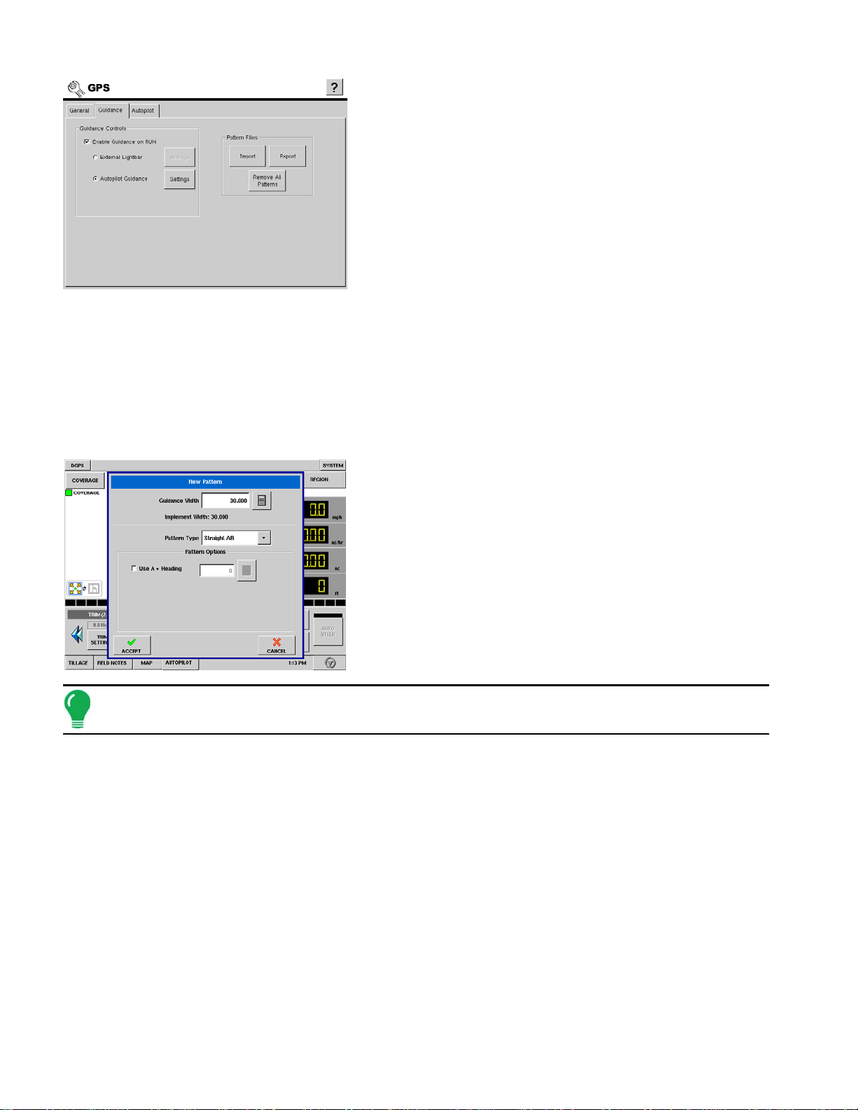
1. Choose a file selection option
From the GPS screen, select the Guidance tab, as shown at left.
Here you can select either Import, Export, or Remove All
Patterns. The import and procedures are explained below.
2. Select Guidance Pattern
To import a guidance line from your external storage card, press
the Import button. A window will pop up and display the guidance
patterns on the card. Highlight the pattern you wish to import and
press Accept.
3. Select Field
Choose the Grower and Field to import the pattern into and press
Accept.
4. Export Guidance Pattern
To export a pattern, either choose the grower and field you would like to export patterns from, or select the
Export All Field Patterns check box. This selection will export all patterns in the display. Press Accept.
Set New Pattern
You can create a new pattern for a field by using the following procedure to set an AB pattern.
1. Choose new pattern
At the Autopilot tab on the Run screen, press the New Pattern
button. The New Pattern window appears, as shown at left. Select
the pattern type in the drop-down menu. Pattern types include:
• Straight AB Line
• A+ Pattern
• Pivot
• Adaptive Curve
• Identical Curve
Note: If you would like to use an A+ Heading, check the check box and use the number pad to enter in the
heading (in degrees). Then press Set A (you do not need to set the B point, as this is done automatically).
2. (Optional) Enter Guidance Width
At the top of the New Pattern window, a default Guidance Width is shown, based on the Implement Width that
you specified in Implement Configuration.
If you wish to change this Guidance Width, enter the new number using the numeric keypad.
When finished, press Accept.
3. Set the A point
To set the A point, press the Set A button on the Autopilot tab. You must now drive the vehicle for the distance of at
least 100 feet before you can set the B point. (The Set B button will not highlight until you have driven that distance).
4. Set the B point
After setting the A point, you will see a message flash at the center of the lightbar stating "Need B". You
must now set a B point.
After driving at least three swath widths, the Set B button appears, allowing you to Set the B point.
Set the B point by pressing the Set B button. You now have created an AB line.
70
Page 85

5. Engage AutoSteer
After setting the AB Line, the lightbar will become active. At the green-colored center of the newlyactivated lightbar, the XTE (Cross-Track Error) message is now displayed.
· To engage the AutoSteer on the current line, you can either press the Auto Steer button immediately.
Or
· To engage the Auto Steer on the next pass, drive the vehicle to that pass, and after you turn the vehicle
around, press the Auto Steer button.
Pause and Resume a Pattern
If you are using the display to follow a set AB Line and wish
to temporarily deviate from this line, you can use the Pause
button to pause the display's logging activity. This feature
could be used, for example, by a vehicle operator who must
refill a sprayer. When paused, the display will continue to
give the distance back to the original pause point position.
GUIDANCE
You can pause a pattern by pressing the Pause button on
the Autopilot tab. Once you do so, a "paws" print will appear
on your display's screen, as shown here.
This paws print indicates the physical location where you
paused the display.
Note: You can pause a pattern even if you have not set the "B" point yet (see top example). If you do so, the
message in the lightbar will read "Need B." If you pause the pattern after you have set your AB Line, then the
lightbar will indicate the distance your vehicle must travel to return to the pause point (see lower example).
Resume a pattern
To resume your pattern, press the Resume button to resume
logging on your AB Line.
71
Page 86

Note: f you press the Resume button before you have returned to the original AB Line, your display will select
the closest AB Line to your vehicle.
Save Pattern
To save a pattern (.pat file), follow the procedure below.
Open the Save Pattern window
First, press the Save Pattern button located at the Run screen's
Autopilot Tab. The Save Pattern window appears, as shown at left.
Name the pattern
Press the keyboard button and enter a unique pattern name. Press
Accept.
Note: To verify that the pattern is saved, you can open the Save Pattern window again by pressing the Save
Pattern button. Your newly saved or named pattern should now appear in the Save Pattern window.
Load Pattern
You can load a pattern from the display's internal memory to the current field by using the following
procedure.
1. Press the Load Pattern button
Press the Load Pattern button on the Run screen's Autopilot tab.
2. Select a pattern
The Load Pattern window appears, as shown at left. Select and
highlight the desired pattern.
If the pattern you selected was an AB Line, that pattern now appears on the Run screen.
Press Accept to continue.
3. (Optional) Enter Guidance Width
After pressing the Accept button, the Shift Pattern window appears. At the top of this window, the default
Guidance Width is shown, based on the Implement Width that you specified in Implement Configuration.
If you wish to change this Guidance Width, enter the new number using the numeric keypad.
Press OK to continue.
72
Page 87

4. If curve, choose Identical or Adaptive
Select either the Identical Curve or Adaptive Curve options. The curve pattern now appears on the
Run screen.
Note: f you selected a curve pattern in Step 2, the Autopilot window will appear, as shown.
Reset Existing Pattern
If you have been using an already-saved pattern, and wish to switch over to a different pattern in the
same field, you can use the Reset Pattern feature by following the steps below.
1. Press Reset
Press the Reset button on the Run screen's Autopilot tab.
2. Press Reset again
The Guidance window appears as shown at left, asking you to
reset the current guidance pattern. Press Reset on the Guidance
window.
3. Create new pattern (optional)
The pattern is now reset. You may now create a new pattern, if
desired.
GUIDANCE
Reset New Pattern
If you have just created one pattern, and wish to use a different pattern in the same field, you can use
the Reset Pattern feature by following the steps below.
1. Press Reset
Press the Reset button on the Run screen's Autopilot tab.
2. Save or Reset Existing Pattern
If you have not saved your existing pattern, the Guidance window appears, warning that your
guidance pattern has not been saved.
• If you choose Save, the existing pattern is saved to the display's internal memory. (For more information see
“Save Pattern” on page 72.
• If you choose Reset, then the existing pattern will be deleted from the display's internal memory, and the
pattern will be reset.
Step 3: Create new pattern (optional)
If you pressed the Reset button, you may now create a new pattern, if desired.
73
Page 88

Remove Patterns
You can remove one or all pattern files from the display's internal memory by following the procedure
below.
1. Press the Load Pattern button
The Load Pattern button can be accessed on the Autopilot tab,
(as long as a pattern is not currently active).
2. Highlight the pattern
Select and highlight the pattern that you wish to remove from the
display. When this pattern is highlighted, the Remove and
Remove All buttons become active.
3. Remove the Pattern
On the Load Pattern window, press either the Remove or Remove
All buttons to delete pattern.
• If you select the Remove button, your selected pattern will be
removed from the display's internal memory.
• If you select the Remove All button, then all guidance patterns for
the current field will be removed from the display's internal
memory.
4. Accept the Remove or Remove All message
The Remove Pattern window appears. The content of this window varies depending upon whether you chose
the Remove or Remove All options.
• If you selected the Remove button, the window states: "This pattern will be permanently removed from
memory."
• If you selected the Remove All button, the window states: "All guidance patterns in this field will be
permanently erased from memory."
5. The pattern is removed
Press the Accept button on the Remove Pattern window. After pressing this button, the pattern file disappears
from the Load Pattern window. Press Accept again.
74
Page 89

TILLAGE
TILLAGE SETUP TABS
CONFIGURATION
TILLAGE
The Tillage setup pages contain all the
necessary settings to configure the display for
logging, mapping, and rate control for Tillage
operations. The combination of Vehicle,
Implement, and Controller are referred to as a
Configuration within the display.
• Configuration
The Configuration Tab is where you can add and edit operating configurations. For more information, see
“Configuration Tab Buttons” on page 75
• Vehicle
The Vehicle Tab is where you can add and edit vehicle configurations. For more information, see
Tab Buttons” on page 79
• Implement
The Implement Tab is where you can add and edit implement configurations. For more information, see
“Implement Tab Buttons” on page 81
.
.
“Vehicle
.
CONFIGURATION TAB BUTTONS
The configuration tab is where tillage configurations are
made and displayed. The configuration settings are also
edited on this tab. Press the Setup button and then the
Tillage button to reach this screen.
• To see a Tillage Configuration Menu, see “Tillage Menu Tree” on
page 170.
• Add button
75
Page 90

Press to add a new tillage configuration. An on-screen wizard will walk you through the setup process in a
step-by-step manner. New Vehicles and Implements can be created during the setup process. For detailed
information see
“Adding a New Configuration” on page 76
.
• Edit button
Press to edit the name of a selected configuration. The on-screen keyboard will be displayed to complete
the desired text edits.
• Remove button
Press to remove a configuration. The vehicle and implement associated with the configuration will not be
deleted.
WARNING: When deleting a configuration all regions and data logged with that configuration will be deleted!
• Configuration Settings
Press to edit the implement switch polarity. For detailed information, see
“Configuration Settings” on page 77
.
• Calibrate Distance
Press to launch speed sensor calibration wizard. For detailed information, see
page 77
.
“Calibrate Distance” on
• Speed Input Settings
Press to select speed input device.
• AutoSwath Settings
The AutoSwath feature automatically increases or decreases the logged width of the tillage equipment,
according to your field's boundaries and previously-tilled areas. The AutoSwath feature includes sensitivity
levels, which compensate for varying degrees of GPS performance. To change these sensitivity levels,
press the AutoSwath Settings button.
Note: You must have an unlock code to activate the AutoSwath feature. If you have been using AutoSwath
with the DirectCommand™ system, the feature is already activated and ready to use. If you have not unlocked
the AutoSwath feature yet, the code can be purchased through your local Ag Leader dealer.
ADDING A NEW CONFIGURATION
To add a new configuration press the Add button. The Operating Configuration Wizard appears, as
shown.
1. Select a Vehicle
Using the drop down box select the vehicle you would like to use
in this configuration. If there are no vehicles in the list press the
New button.
For help with the adding a new vehicle wizard see
Vehicle” on page 80
.
Press Next to continue.
“Adding A New
2. Select Implement
Using the drop down box select the implement you would like to use in this configuration. If there are no
implements in the list, press the New button.
76
Page 91

For help with the adding a New Implement Wizard, see
Press Next to continue.
3. Select Implement Switch Polarity
If you will be using an implement switch, choose standard or reversed polarity. If an implement switch is not
in use, select None.
Press Next to continue.
4. Select Ground Speed Source
Select your ground speed source. If you will be using GPS as the primary you will need to select a
secondary source.
Press Next to continue.
5. Edit Configuration Name
Use the Keyboard button to edit the suggested configuration
name. Press Finish to complete the configuration process.
“Adding A New Implement” on page 82
.
TILLAGE
CONFIGURATION SETTINGS
To access the equipment configuration settings screen first highlight a configuration in the list and then press the Configuration Settings button.
Implement Switch Setting
If you will be using an implement switch choose standard or
reversed polarity. If an implement switch is not in use, select
none. Press Accept when done.
CALIBRATE DISTANCE
If you are not using GPS for ground speed, then after you have created a configuration you must
calibrate the ground speed input for accurate speed and area calculations. If you are using GPS, it is
recommended to calibrate distance in the event of GPS loss.
Select a Configuration from the list and press the Calibrate Distance button to calibrate the radar,
track or wheel speed sensor. This calibration is specific to that combination of Vehicle, Implement, and
Controller.
77
Page 92

1. Select Speed Input
The Speed Sensor Calibration wizard appears, as shown at left.
Select the sensor type to calibrate.
Press NEXT to continue.
2. Calibration Distance
The display defaults to 100 feet (meters) distance for calibration.
Press Edit Distance to change if needed. This value must match
the actual distance of the course driven for calibration.
Press NEXT to continue.
3. Start Driving Course
Follow the on-screen directions and press START to begin the calibration process.
4. Course Completed
Drive vehicle over the measured course and press STOP.
Press NEXT to continue to final step.
5. Calibration Completed
Press FINISH to complete calibration and store the calculated value.
Note: Calibration settings can be manually adjusted if desired by pressing Enter CAL Number and making
small changes to the setting.
Speed Input Settings
• Speed Input Settings Tab
Press the Speed Input Settings button on the Configuration Tab,
and the Speed Input Settings window appears, as shown at left.
From here, select the primary and backup Ground Speed Source.
AUTOSWATH SENSITIVITY SETTINGS
The AutoSwath feature automatically increases or decreases
the logged width of the tillage equipment, according to your
field's boundaries and previously-tilled areas. For a more
detailed explanation of the AutoSwath feature, see
Swath Control, Run Screen Operation” on page 86.
The AutoSwath feature includes sensitivity levels, which
compensate for varying degrees of GPS performance. To
change sensitivity levels, select the Configuration tab, and
press the AutoSwath Settings button. These sensitivity
settings are specific to that combination of Vehicle and
Implement.
“Automatic
78
Page 93

If swath adjustments are performing inaccurately, adjust the sensitivity accordingly. Sensitivity 3 is the
default setting. Other settings include:
• Sensitivity 5
Use with RTK or DGPS sub-meter, terrain-compensated GPS.
• Sensitivity 4
Use with RTK or DGPS sub-meter GPS. Terrain compensation recommended.
• Sensitivity 3
Use with sub-meter accurate GPS.
• Sensitivity 2
Use with 1+ meter accurate GPS.
• Sensitivity 1
Swath segments are all on or all off. Use with 1+ meter accurate GPS.
You must have an unlock code to activate the AutoSwath feature. If you have been using AutoSwath
with the DirectCommand™ system, the feature is already activated and ready to use. If you have not
unlocked the AutoSwath feature yet, the code can be purchased through your local Ag Leader dealer.
VEHICLE CONFIGURATION
TILLAGE
VEHICLE TAB BUTTONS
The vehicle tab provides functionality for setting up and
configuring additional vehicles. The vehicle list will show any
vehicles that have already been created.
To see a Tillage Configuration Menu that includes Vehicle
Tab information, see
• Add
button allows you to add a new vehicle. A wizard will walk you through setting up the vehicle. For detailed
information see
• Edit Name
button allows you to edit the name of a vehicle in the list. To edit highlight the name of a vehicle in the list
and then press this button. Use the on screen keyboard to edit the name.
• Remove
button allows you to remove a vehicle. The implement and any regions and configurations using it will be
deleted.
“Adding A New Vehicle” on page 80
.
“Tillage Menu Tree” on page 170.
WARNING: When deleting a vehicle all regions and configurations using it will be deleted!
• GPS Offsets
79
Page 94

button allows you to specify the location of the GPS antenna in relation to the vehicle. A wizard will walk
you through these edits. It also allows you to enter the distances from the rear axle to the different
implement mounting positions on the tractor. See
“GPS Offsets” on page 80
.
ADDING A NEW VEHICLE
To start the process of adding a new vehicle press the Add button.
1. Choose Vehicle Type
Choose the vehicle type from the drop down list.
Press Next to continue.
2. Enter Vehicle Make and Model
Use the keyboard buttons to enter the vehicle's make and model.
Press Next to continue.
3. Finish
Use the keyboard button to edit the name of the vehicle.
Press FINISH to complete the setup process.
GPS OFFSETS
After completing the process of setting up a Vehicle,
advanced GPS Offsets must be configured. The GPS Offsets
define where machine rear axle and hitch is in relation to the
GPS antenna. These settings are used by mapping, product
control, and Automatic Swath Control.
Antenna Offsets
The Antenna Tab contains three different settings. Accuracy when
measuring for a specific setting is essential to ensure proper
machine performance.
• Measure and enter the horizontal distance from the rear axle to
the position of the GPS antenna. Select IN FRONT or BEHIND from
the list box to indicate the position of the antenna in relation to the
rear axle.
• Measure and enter the horizontal distance from the center line of the vehicle to the position of the GPS
antenna. Select LEFT or RIGHT to indicate the position from the vehicle centerline.
• Measure and enter the vertical height of the antenna above the ground.
Note: Accuracy when measuring for a specific setting is essential to ensure proper machine performance.
80
Page 95

Hitch Tab Settings
The Hitch tab allows you to enter in the distance from four
different mounting positions on the tractor to the rear axle. Use
the Number Pads to enter these values in if using the hitch
point.
Note: Accuracy when measuring for a specific setting is essential to ensure proper machine performance.
IMPLEMENT CONFIGURATION
IMPLEMENT TAB BUTTONS
Individual implements are setup and configured from the
implement tab. The implement list displays all previously
setup implements that are available for use when creating
new configurations.
TILLAGE
To see a Tillage Configuration Menu that includes information
on the Implement Tab, see
• Add button
Press to add a new implement. A wizard will walk you through setting up the implement. For detailed
information see
• Edit Name button
Press to edit the name of a selected implement from the list. The on-screen keyboard will be available to
make any required edits.
• Remove button
Press to remove a selected implement. The implement and any regions and configurations using it will be
deleted.
WARNING: When deleting an implement all regions and configurations using it will be deleted!
• Implement Offsets button
Press to edit the implement offsets, distance from tractor hitch to application point, and distance from front
hitch to rear hitch of the implement. An on-screen wizard will walk you through the edit process. For detailed
information see
“Adding A New Implement” on page 82
“Implement Offsets” on page 82
.
.
“Tillage Menu Tree” on page 170.
81
Page 96
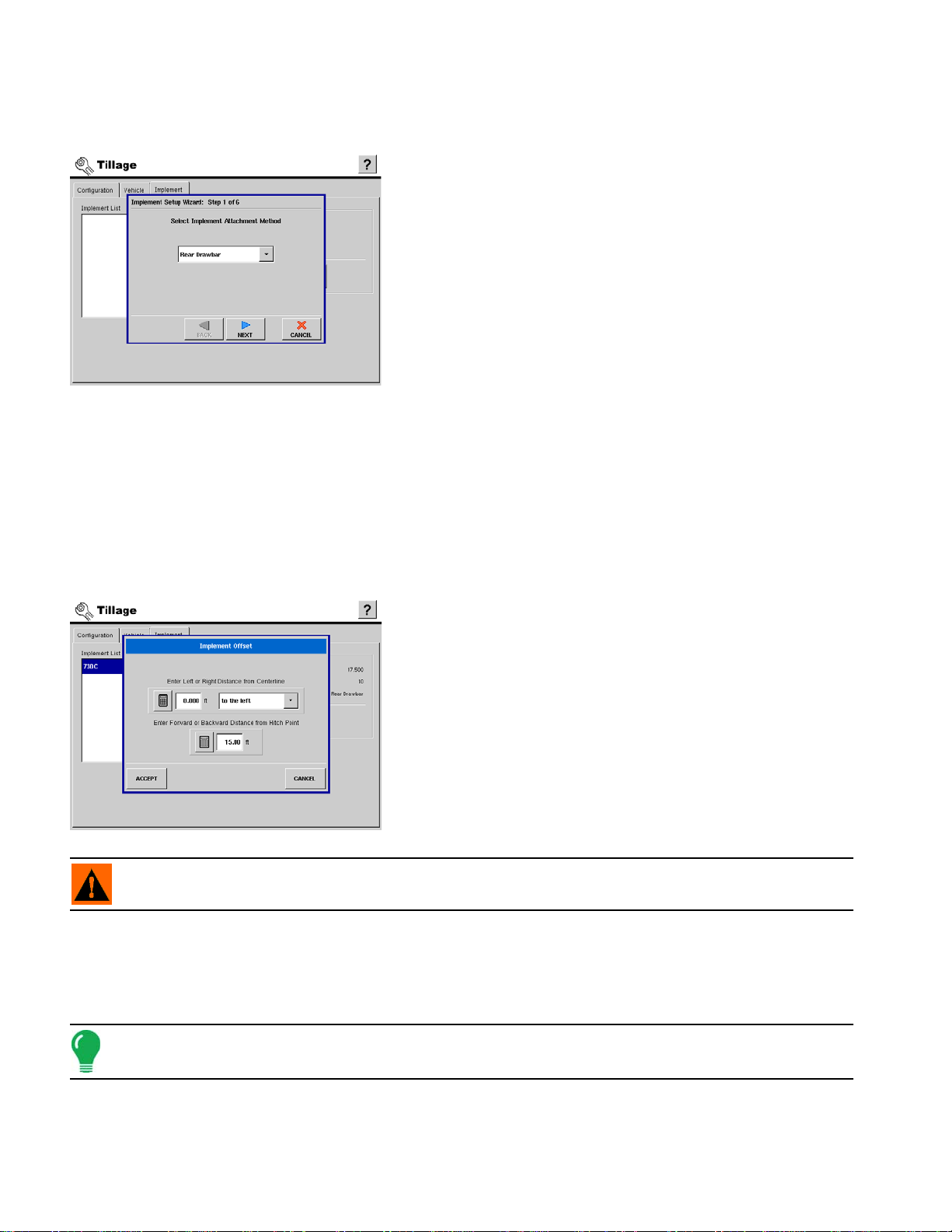
ADDING A NEW IMPLEMENT
To add a new implement, press the Add button. The Implement Setup Wizard appears, as shown.
1. Select Attachment Method
Use the drop down list to select an implement attachment
method.
Press NEXT to continue.
2. Enter Full Swath Width
Use the numeric keypad to enter the full swath width of the
implement.
Press Next to continue.
3. Enter Hitch to Application Point Distance
Enter the distance from the hitch to the application point using the
numeric keypad.
Press Next to continue.
4. Enter the Implement Name
Use the keyboard button to enter a name for the implement.
Press Finish to complete the implement setup process.
IMPLEMENT OFFSETS
After completing the initial process of configuring an
Implement, you must enter accurate values in the Implement
Offsets. Press the Implement Offset button, and the
Implement Offset window appears, as shown.
Enter distances from hitch point and centerline
• Use the first numeric keypad to enter the distance from the midpoint of the swath section to the machine’s centerline. Select to the
left/to the right to indicate the direction the swath section is located
from the vehicle centerline.
• Use the second numeric keypad to enter the distance that the
swath section is located from the hitch point.
Press the Accept button when finished.
WARNING: Accuracy when measuring and entering implement offsets is required to ensure proper
machine performance.
RUN SCREEN OPERATION
RUN SCREEN BUTTONS
Note: In order to log data on the Run Screen, you must first go to the field button and accept a field,
configuration, and region. For detailed information see “Field Button (While Not Logging)” on page 84.
82
Page 97

TILLAGE
• Field button
The Field button functionality changes based upon the status of the master switch. If the master is off it
allows you to change grower, farm, field, and configuration. If the master status is on it allows you to view
field totals. For more information, see
Logging” on page 85
.
“Field Button (While Not Logging)” on page 84
, and
“Field Button While
• Region button
Press to change and name regions of the field. For more information, see
“Region Button” on page 85
.
• System button
Press to access diagnostic information about the internal memory, display information, and CAN module
information.
• DGPS button
• AutoSwath check box
The AutoSwath feature automatically increases or decreases the logged width of the tillage equipment
according to your field's boundaries and previously-tilled areas. Check the AutoSwath check box to enable
the AutoSwath feature. For more information, see
page 86
.
Note: You must have an unlock code to activate the AutoSwath feature. If you have been using AutoSwath
with the DirectCommand™ system, the feature is already activated and ready to use. If you have not unlocked
the AutoSwath feature yet, the code can be purchased through your local Ag Leader dealer.
The master button controls area logging. When the switch is set to green area is being recorded
and displayed on the map.
“Automatic Swath Control, Run Screen Operation” on
83
Page 98

When the master button is set to off area is not being recorded and the map will stop drawing.
The box will remain red until the button is pushed again to set it to auto.
RUN SCREEN - MAIN TABS
Tillage Tab
The tillage tab on the Run Screen contains controls related to
data logging during tillage operations.
• Use the master switch to turn area logging off and on.
• The Swath display allows you to change the amount of swath that
is being mapped for area calculation. The full implement width is displayed as 10 sections and can be
changed in 10% increments. To adjust the swath width use the arrow keys on either side of the swath display.
The full swath button allows you to go from any partial swath back to the full swath position.
Field Notes Tab
Map Tab
FIELD BUTTON (WHILE NOT LOGGING)
Start of tillage in a field is accomplished by setting up a Field Operation at the Run Screen. This process
is similar regardless of the type of field operation currently taking place. To begin, press the Field button
on the Run screen, and the Field Operation Wizard appears, as shown.
1. Select Grower, Farm, Field
Choose the field for tillage by making the proper selections from
the Grower, Farm, and Field list boxes.
If the Filter Fields by Farm check is cleared, the display will
display all fields in the Field list box regardless of what farm the
fields are associated with.
Press NEXT to continue.
84
Page 99

Note: You may view Field Totals by pressing the Field Totals button on the Field Operation Wizard. For more
information on field totals, see “Field Button While Logging” on page 85.
2. Choose Configuration
Select the Operating Configuration that relates to the equipment in use.
Press NEXT to continue.
3. Finish
Press Finish to start the tillage operation.
TILLAGE
REGION BUTTON
The Region Selection window is made available during
initial tillage operation setup and anytime during a tillage
operation by pressing the REGION button.
Press New to add a region to an existing tillage operation. The
display uses sequential numbers to assign default names to field
regions.
Press the keyboard button to edit the Region name.
FIELD BUTTON WHILE LOGGING
If the Field button is pressed while logging data, the Field Totals
window will show the field totals.
85
Page 100

DISPLAY ITEMS
The display items selection window can be accessed by
pressing any one of the four display items that are active on
the Run screen.
Once the display items window is visible, press on the display item
you would like to display. It will then be available on the Run screen.
• Area button
Displays the area that has been tilled in that field region.
• Area Per Hour button
Shows the instantaneous productivity.
• Ground Speed button
Shows the instantaneous ground speed.
• Distance button
Shows the total distance driven in the region.
AUTOMATIC SWATH CONTROL, RUN SCREEN OPERATION
The AutoSwath feature automatically increases
or decreases the logged width of the tillage
equipment according to your field's boundaries
and previously-tilled areas. By doing so, the
display records a change in logging data, even
though no mechanical change has actually taken
place. By recording changes to your logging
data, AutoSwath ensures the display's correct
area calculation, which also improves the
accuracy of your field summaries and reports
AutoSwath explained
As your vehicle travels beyond a tilled area, the AutoSwath feature automatically changes the active width of
the tillage equipment by the use of a "stair-step" method, in which the logged width is reduced by successive
amounts.
86
 Loading...