

Page 1

GPS 4100
INSTALLATION
AND
GENERAL INSTRUCTIONS
Page 2

Page 3

GPS 4100 Contents
Ag Leader Technology
Important Notices
Before beginning installation of your GPS 4100, please take the time to
thoroughly read these instructions. Signal words (CAUTION,
IMPORTANT, and NOTE) are provided to draw attention to
information that is important for the safe/correct installation and
operation of this product.
• CAUTION--will alert you to situations that will impact the
physical safety of you or others.
• IMPORTANT—will alert you to the potential for damage to the
product or loss of data.
• NOTE--will provide you with additional information to simplify a
procedure or clarify a process.
After completing installation of the GPS 4100 we recommend that you
place these instructions in the Options Section of your PF3000 or
PF3000 Pro Operator’s Manual to prevent their loss.
To receive upgrade/update information of this product you must send
in or fax the Registration Form. Refer to the Registration Form for
address and fax number.
Item Page
Updating Operating Program 2
Parts, Tools for Antenna Installation 3
Installing the Antenna 3
Routing the Cable to the Cab 4
General Information 6
WAAS Selection 6
Satellite Selection 8
Diagnostic Screen 14
NMEA Message 16
GPS/Port Configuration 16
Troubleshooting 17
Parts List 18
Updating GPS Firmware 19
Installing FlashLoader 19
Installing AgRemote 20
Commercial Satellite Frequencies and Contacts 21
March 2001
1
Page 4

UpDating Operating Program
GPS 4100
Ag Leader Technology
Updating
Operating
Program
1 Using a computer card reader, copy the file "upgrade.pld" to
2 Insert the memory card in the monitor and turn on the monitor.
3 The monitor will detect a new operating program on the card.
4 The monitor will erase the old program and install the new
5 Check some of the field and load information and settings to
Your operating program version must be greater than 3.22 (greater than
3.23 for cotton mode) for the PF3000 to use the GPS 4100. The version
of the monitors operating program currently installed is displayed when
you turn on the PF3000.
If your version is before this, contact Ag Leader Technology at 515-2325363 to obtain an update. You may also download the update off the Ag
Leader web site at www.agleader.com.
Perform the following steps to install the new operating program:
Step Action
the memory card.
Press the SHOW FILES key. The monitor will display the
version number of the current program and new program.
Press ACCEPT key to install the new version.
program.
double check that the new program is operating correctly
2
March 2001
Page 5

GPS 4100
Ag Leader Technology
Parts, Tools for
Antenna
Installation
Installing the
Antenna
Installing with antenna magnet:
Installing antenna with L-bracket:
The following parts and tools are needed to install the antenna and its
bracket:
• 5/16 in. self tapping bolts • L-bracket
or 5/16 in. bolts with serrated nuts • Antenna
• 1/4 in. drill bit for thin metal • Marker
or 9/32 in. for thicker metal • Punch
• Antenna cable • Hand drill
• Three white cable tie-downs
with self tapping screws
• Three white cable tie-downs
The antenna magnet is very powerful and will stick securely to any metal
surface. If needed, an L-bracket for mounting the antenna is provided.
The L-bracket is used for mounting the antenna (especially on combines)
but not necessary.
Determine a mounting location that is in the center of the swath and the
highest point of the vehicle. Ensure that no part of the machine is
blocking a clear view of the sky to the antenna. Ensure the antenna is
mounted low enough so it won't be knocked off when pulling the vehicle
into shed. Find a mounting location that if it does get struck it can slide
off.
Step Action
1 Locate a flat metal surface on the vehicle; set the antenna
2 Ensure you leave some slack in the cable between the
Step Action
1 Place the top surface of the bracket 1/4-in. above the top of
Installing Antenna
on it ensuring the magnet adheres securely.
antenna connection and first tie down. Route cable to cab
using cable tie-downs every 12-18 inches to secure cable.
the highest metal surface of the vehicle. This ensures the
antenna is the highest point of the vehicle and can slide off
if struck.
March 2001
3
Page 6
Installing Antenna
Routing the Cable
to the Cab
GPS 4100
Ag Leader Technology
2 After you determine this position, place the L-bracket against
the metal surface, mark and punch the places you will be
drilling.
3 Drill the holes in the surface and attach bracket as follows:
If the metal is … Then use a…
Thin 1/4-in. drill bit and 5/16 in.
bolts with serrated nuts.
Thick (1/8 in. or more) 9/32 in. bit and self-tapping
bolt.
4 Center the antenna on the top surface of the bracket. Place
the antenna so the cable connector is pointing towards the
right side of combine or vehicle.
5 Attach the cable to antenna, connecting the end with the plug
to antenna.
6 Attach a white cable tie-down to metal surface 1 or 2 ft
below and 6 in. to right of the L-bracket.
NOTE: You may need to increase the above
distances, depending on the type of grain track
extension you are using.
7 Place another white tie-down 3 to 5 ft to the right of the first
tie-down.
8 Use a cable tie and attach the cable to the first white tie-
down leaving some slack in cable between antenna
connection and tie down to allow for strain relief if the
antenna is knocked off the L-bracket.
9 Use another cable tie to attach the cable to the second tie-
down.
10 Route cable to cab using cable tie-downs to secure cable.
Follow these steps to route cable into the cab:
Step Action
1 Find a place on the right side or bottom of the cab to route
cable into cab (the point of entry is up to you).
IMPORTANT: The cable can be routed through
windows or doors but make sure that there will be
no damage to the cable.
4
March 2001
Page 7

GPS 4100
Ag Leader Technology
Step Action
2 Attach the cable from the antenna to Port 1 of the PF3000
Figure 2. Cable attachment for PF3000 Pro without GPS, Optional Lightbar (if
Port 1
Figure 1. Cable attachment for PF3000, Optional Lightbar (if used) and GPS
AUX Port 1
Installing Antenna
or AUX 1 on the PF3000 Pro without GPS. See Figures 1
and 2.
NOTE: If you are using the optional Lightbar,
refer to Figures 1 and 2 for cable attachment.
NOTE: If you are NOT using the optional
Lightbar, tie the excess cable so it will not interfere
with the operations inside the vehicle. The
connector that attaches to the Lightbar will not be
connected to anything.
4100
used) and GPS 4100
March 2001
5
Page 8

General Instructions
Overview
General
Information
WAAS Selection
The GPS 4100 requires no initial setup to begin fieldwork. The PF3000
or PF3000 Pro will display a "D" or "G" on the top right hand corner of
the display to indicate a GPS signal. A "D" indicates that you have a
differential signal. A "G" indicates that you have a GPS signal and your
GPS receiver is tracking four or more satellites (which means you can
get an elevation reading). A lower case "g" indicates that you have a
GPS signal but your GPS receiver is tracking only three satellites which
means you can not get an elevation reading. Your GPS receiver must
track four or more satellites to get an elevation reading. You may wish
to use the GPS to show your ground speed, which requires changing the
ground speed sensor settings. Refer to Primary and Secondary Speed
Sensor under Vehicle Setup in the PF3000 or PF3000 Pro Operator’s
manual for instructions.
Wide Area Augmentation System (WAAS) differential correction is an
alternative to subscription based satellite differential correction.
The following provides information to change factory settings on the
GPS 4100.
If you are going to use the WAAS option complete the following:
GPS 4100
Ag Leader Technology
IMPORTANT: WAAS is currently free of charge, and is
being funded by the Federal Aviation Administration (FAA).
WAAS is currently in test mode, and Ag Leader Technology
can not guarantee the availability or quality of its position
signals. Only two (2) WAAS satellites are currently covering
North America.
Step Action
1 Press Menu key on PF3000 until SETUP is displayed, press
SETUP key.
2 Press bottom left or right arrow key until GPS is displayed and
press GPS key. You should now see the screen shown in
Figure 3.
6
March 2001
Page 9

GPS 4100
GPS SETUP
NMEA MESSAGE
GPS/PORT
CONFIGURATION
BEACON DIFFERENTIAL
SATELLITE DIFFERENTIAL
LIGHTBAR
GUIDANCE
SATELLITE DIFFERENTIAL SETUP
Ag Leader Technology
Step Action
3 At the GPS SETUP screen (Figure 3) scroll down to Satellite
General Instructions
EDIT
Differential Mode with down arrow key and press EDIT. You
should now see the screen shown in Figure 4.
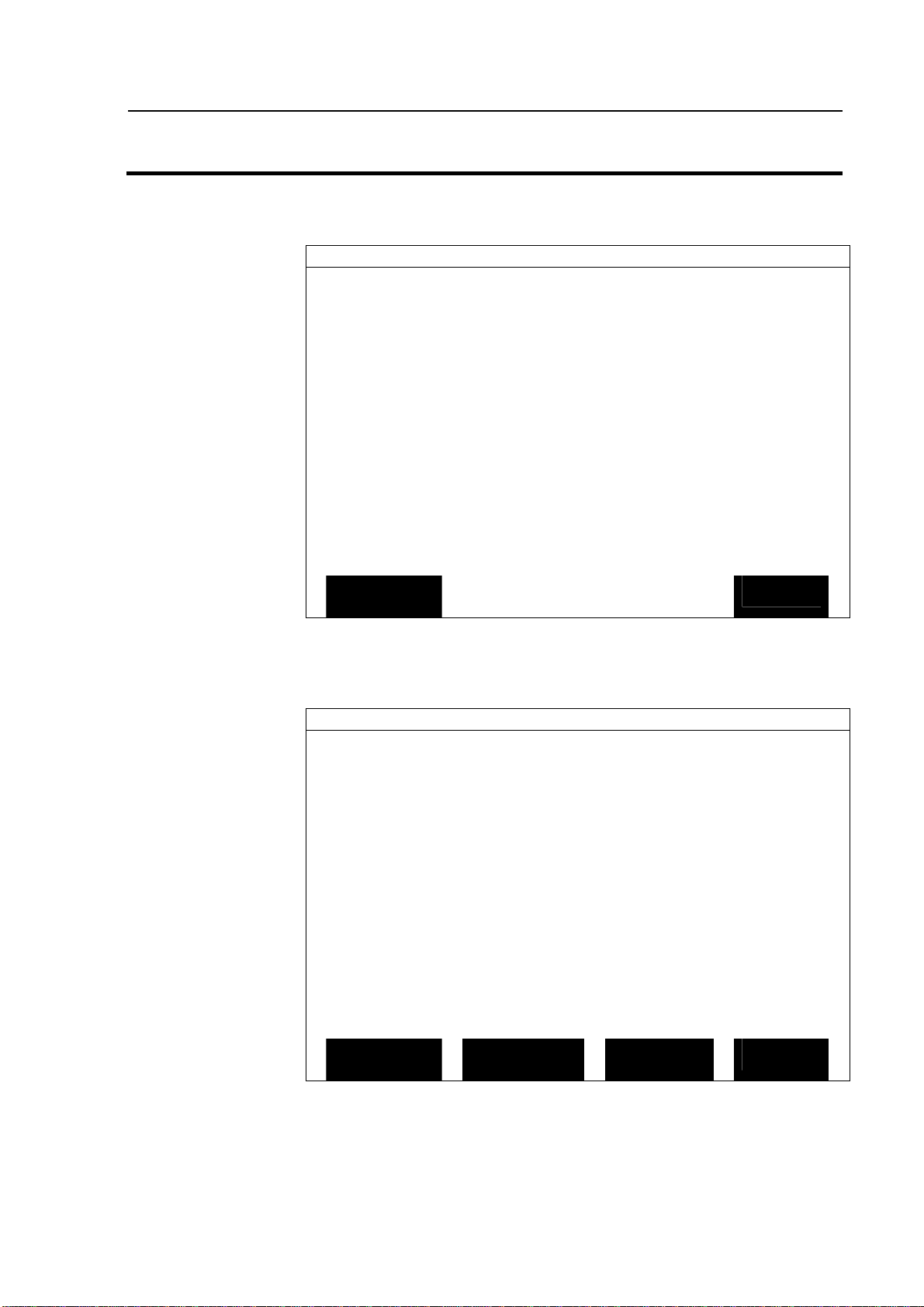
Figure 3. GPS SETUP Screen
EXIT
Differential Source WAAS
Differential Provider
Satellite Frequency 0000.0000
Satellite Baud Rate 0000
Provider User Code 0
OMNISTAR Code 000000000000000000000000
Subscription Expiration 00/00/0000
EDIT
EXIT
Figure 4. Satellite Differential Setup Screen
Step Action
4 At the SATELLITE DIFFERENTIAL SETUP screen (Figure
4) Differential Source will be highlighted, press EDIT key and
use UP or DOWN ARROW key until WAAS is displayed and
press ACCEPT key.
5 Now press EXIT key to return to GPS SETUP screen, press
EXIT key again to return to the main operating screen.
March 2001
7
Page 10

General Instructions
GPS
SETUP
NMEA MESSAGE
GPS/PORT CONFIGURATION
BEACON DIFFERENTIAL
SATELLITE DIFFERENTIAL
LIGHTBAR
GUIDANCE
SATELLITE DIFFERENTIAL SETUP
Satellite Selection
If you will be using the satellite differential option, complete the following
steps depending on which service provider you select.
GPS 4100
Ag Leader Technology
Step Action
1 Press Menu key on PF3000 until SETUP is displayed, press
SETUP key.
2 Press bottom left or right arrow key until GPS is displayed and
press the GPS key.
EDIT
Figure 5. GPS SETUP Screen
Step Action
3 At the GPS SETUP screen (Figure 5) scroll down to Satellite
Differential Mode with down arrow key and press EDIT.
Differential Source Satellite
Differential Provider Omnistar
Satellite Frequency 0000.0000
Satellite Baud Rate 0000
Provider User Code 0
OMNISTAR Code 000000000000000000000000
Subscription Expiration 00/00/0000
EDIT
Figure 6. Satellite Differential Setup Screen
EXIT
EXIT
8
March 2001
Page 11

GPS 4100
SATELLITE DIFFERENTI
AL SETUP
Ag Leader Technology
If you
will be
using…
Omnistar At SATELLITE DIFFERENTIAL SETUP screen (Figure 6)
General Instructions
Then…
Differential Source will be highlighted, press EDIT key and
use up or down arrow key until Satellite is displayed and
press ACCEPT key. Scroll down to Differential Provider
and press EDIT key. Use the up or down arrow key until
Omnistar is displayed and press ACCEPT key. Scroll down
to Satellite Frequency and press EDIT key. Use the up or
down arrow key to select your region (Figure 7) and press
ACCEPT key. If you will be using a custom frequency
(Figure 8) with this provider, scroll down to Custom (1) and
push EDIT NAME key. Use the up/down and left/right
arrow keys to name this frequency. Push EDIT VALUE
key and use the up/down and left/right arrow keys to enter
the frequency. Push ACCEPT key. Your customized
frequency should appear as the Satellite Frequency.
Omnistar Satellite Beacon Frequencies:
Eastern USA 1556.825
Central USA 1554.497
Western USA (1) 1551.429
Western USA (2) 1551.489
Australia 1558.510
Europe 1531.230
South America (1) 1541.705
South America (2) 1541.715
Custom (1) 0000.0
Custom (2) 0000.0
EDIT
EXIT
Figure 7. Omnistar Region Frequencies Screen
March 2001
9
Page 12

General Instructions
SATELLITE DIFFERENTIAL SETUP
Omnistar Satellite Beacon Frequencies:
Eastern USA
1556.825
Central USA
1554.497
Western USA (1)
1551.429
Western USA (2)
1551.489
Australia
1558.510
Europe
1531.230
South America (1)
1541.705
South America (2)
1541.715
Custom (1)
0000.0
Custom (2)
0000.0
ED
IT
EDIT
GPS 4100
Ag Leader Technology
EDIT
NAME
VALUE
Figure 8. Custom Frequency Screen
If you will
Then…
be using…
Omnistar Before contacting Omnistar you must have the Receiver
Serial Number (Found on the Add-On GPS Diagnostic
screen – Press DIAG key, GPS key, Add-On GPS key) and
the Provider User Code (this value will appear on screen
shown on Figure 6 when Differential Provider is set to
Omnistar). Call the Omnistar subscription number (1-888666-4782 in the USA) and give them these two numbers.
Omnistar will then give you a 24-digit code. Key the code
into the right of Omnistar Code (See Figure 8) using up
and down arrow keys. Once the code is entered, press
ACCEPT key to send the code to the unit. Now press
EXIT key to return to GPS SETUP screen, press exit key
to return to operating screen. After 30 minutes, the
receiver should start receiving corrections and display a
"D" in the upper right hand corner of the PF3000.
EXIT
10
March 2001
Page 13

GPS 4100
SATELLITE DIFFERENTIAL SETUP
Ag Leader Technology
Differential Source Satellite
Differential Provider RACAL
Satellite Frequency 0000.000000
Satellite Baud Rate 0000
Provider User Code 0000
OMNISTAR Code 000000000000000000000000
General Instructions
ACCEPT
Figure 9. Satellite Differential Setup.
If you will
Then…
be using
RACAL…
RACAL At SATELLITE DIFFERENTIAL SETUP screen (See
Figure 9) Differential Source will be highlighted press
EDIT key and use up or down arrow key until Satellite is
displayed and press ACCEPT key. Scroll down to
Differential Provider and press EDIT key. Use the up or
down arrow key until RACAL is displayed and press
ACCEPT key. Scroll down to Satellite Frequency and
press EDIT key. Use the up or down arrow key to select
your region (Figure 10) and press ACCEPT key. Use the
up or down arrow key to select your region and press
ACCEPT key. If you will be using a custom frequency
(Figure 11) with this provider, scroll down to Custom (1)
and push EDIT NAME key. Use the up/down and
left/right arrow keys to name this frequency. Push EDIT
VALUE key and use the up/down and left/right arrow keys
to enter the frequency. Push ACCEPT key. Your
customized frequency should appear as the Satellite
Frequency.
CANCEL
March 2001
11
Page 14
General Instructions
SATELLITE DIFFERENTIAL SETUP
RACAL Satellite Beacon Frequencies:
North American East
1553.345
Nor
th American Mtn
1554.350
North American West
1556.225
Australia
1553.525
Europe
1531.210
South Africa
1552.640
Custom (1)
0000.0
Custom (2)
0000.0
Custom (3)
0000.0
Custom (4)
0000.0
SATELLITE DIFFERENTIAL SETUP
RACAL Satellite Beacon Frequencies:
North American East
1553.345
North American Mtn
1554.350
North American West
1556.2
25
Australia
1553.525
Europe
1531.210
South Africa
1552.640
Custom (1)
0000.0
Custom (2)
0000.0
Custom (3)
0000.0
Custom (4)
0000.0
EDIT
EDIT
GPS 4100
Ag Leader Technology
ACCEPT
Figure 10. RACAL Region Frequencies Screen
EXIT
Figure 11. Custom Frequency Screen
12
ACCEPT
March 2001
NAME
VALUE
EXIT
Page 15

GPS 4100
S
ATELLITE DIFFERENTIAL SETUP
Ag Leader Technology
If you will
be using
RACAL…
Before contacting RACAL you must have the Receiver
General Instructions
Then…
Serial Number (Found on the Add-On GPS Diagnostic
screen – Press DIAG key, GPS key, Add-On GPS key) and
the Provider User Code (this value will appear on screen
shown on Figure 6 when Differential Provider is set to
RACAL). Call the RACAL subscription number (1-888-
434-7757 in the USA) and give them these two numbers.
RACAL will activate a code for the serial number that was
given. After the serial number is called in, press the EXIT
key (Figure 12) to return to operating screen. A "D"
should appear in the upper right hand corner of the
PF3000. Within 15 to 30 minutes the receiver should start
receiving corrections from RACAL.
Differential Source Satellite
Differential Provider RACAL
Satellite Frequency 1553.345000
Satellite Baud Rate 1200
Provider User Code 8111
OMNISTAR Code 000000000000000000000000
ACCEPT
Figure 12.
EXIT
March 2001
13
Page 16

General Instructions
GPS DIAGNOSTICS
UTC TIME
00:00:00
Latitude
0000.0000 S
Longitude
0000.0000 E
Elevation
0 ft
GPS speed
0.0 MPH
Number of satellites
0
Differential Status
OFF
Beacon/Sat. Frequency
0.000
Differential SNR
0.0
HDOP/PDOP
0.0
0/0.00
Rcvr Voltage
13.73
ADD
-
ON
ADD
-
ON GPS DIAGNOSTICS
DG
Product Id
AL 9114
Trimble Firmware Version
1.71
Firmware Date
6/8/2000
Receiver Serial Numb
er 0224004738
PV Filter Status
ON
Everest Multipath
OFF
Fast Update Rate
OFF
Guidance Status
OFF
Diagnostic Screen
The diagnostic screen (Figure 13) provides troubleshooting and
reference information for the GPS. Provided are definitions of
screen terms.
Press the DIAG key to view Figure 13. Then press the Add-On
GPS key to view Figure 14.
GPS 4100
Ag Leader Technology
GPS
FORMAT
CARD
COPY TO
CARD
Figure 13. GPS Diagnostics Screen
EXIT
Figure 14. Add-On GPS Diagnostic Screen
14
March 2001
EXIT
Page 17

GPS 4100
UTC TIME
Latitude
Longitude
Elevation
GPS Speed
Number of Satellites
Differential Status
Beacon/Satellite Frequency
Differential SNR
HDOP/PDOP
Ag Leader Technology
Greenwich, England
NOTE: The US Coast Guard may also refer to GMT as "ZULU".
fractional minutes.
minutes.fraction minutes.
is using. The unit can track a maximum of twelve satellites.
differential signal is being used.
differential source that the GPS is using for the location of the
differential source.
strength of the correction signal in relation to the amount of
background noise that can interfere with signal reception. A good
SNR is 10 to 18.
indicates the quality of the horizontal GPS position. Position
Dilution of Precision (PDOP) is a unitless measure indicating
when the satellite geometry can provide the most accurate results.
When satellites are spread around the sky, the PDOP value is low
and the computed position is more accurate. When satellites are
grouped close together the PDOP is high and the positions are
less accurate.
General Instructions
: Greenwich Mean Time (GMT), the current time in
: Current latitude of the receiver in degrees-minutes.
: Current longitude of the receiver in degree-
: Current elevation of the receiver in feet.
: Current speed of the receiver in miles-per-hour.
: Indicates the number of satellites the unit
: Indicates ON or OFF, telling you whether a
: Indicates the frequency of the
: Signal-to-noise-ratio (SNR) indicates the
: Horizontal Dilution of Precision (HDOP)
March 2001
15
Page 18

General Instructions
NMEA MESSAGES
G
PS/PORT CONFIGURATION
Position Rate
1 Hz
NMEA Messages
The GPS unit uses Trimble TSIP to provide position information to the
PF3000. This means that NMEA messages (Figure 15) do not need to be
set and will not be displayed on the NMEA diagnostic screen.
GGA ON
GLL OFF
VTG ON
GSV OFF
GSA OFF
ZDA OFF
ALM OFF
RMC OFF
MSS ON
EDIT
Figure 15. NMEA Messages Screen
GPS/Port
Configuration
The GPS/Port Configuration screen (Figure 14) requires no
adjustment at this time. This screen will be used for future options
for the AUX Port of the GPS.
Ag Leader Technology
GPS 4100
EXIT
Figure 16. GPS/ Port Configuration Setup Screen
16
NEMA Output rate ASAP
AUX port parity NONE
P/v FILTER ON
Port AUX
Output baud rate 19200
Output type NMEA
Input baud rate 19200
Input type None
EDIT
March 2001
EXIT
Page 19

GPS 4100
•
•
•
•
•
•
Ag Leader Technology
Troubleshooting
Problem Cause Solution
Monitor dims when
using external power
source for PF3000.
After powering up the
PF3000 you are
unable to enter the
GPS setup screen.
I lose "D" around
buildings when using
WAAS Differential
The following is a list of problems that you may encounter with the GPS
4100 and suggestions for troubleshooting. If you have a problem with the
system, please review the list before calling Ag Leader Technology. If
your troubleshooting does not solve the problem, please call Technical
Support at Ag Leader Technology (515-232-5363).
External power
source for PF3000
does not provide
enough power.
PF3000 did not
properly detect the
GPS.
WAAS signal isn't
being transmitted.
• The WAAS
satellite you are
using is being
blocked.
Troubleshooting
New external power source is
available to support GPS to
PF3000.
Power the PF3000 down and then
restart.
• Ensure the connector cable
between the PF300 and GPS is
properly connected.
• If these actions fail, please call
Technical Support at 515-232-
5363.
Go to Raytheons website
(wwws.raytheontands.com/waas/)
and check the current status of
WAAS transmission.
• There are only two (2) WAAS
satellites that are low on the East
and West horizon. Building and
tree lines can easily block the
signal.
March 2001
17
Page 20

Parts List
Parts List
—
GPS 4100
Part Name/Description
Part Number
Quantity
Manual Insert
– GPS 4100
3000368
1
GPS 4100
– Antenna/Receiver
3000332
1
Antenna Bracket (L
-
shape)
2000161
1
Cable Kit (PF3000)
2001252
1
Cable Kit (PF Pro)
2001253
1
Cab/Cable Install Kit
3000505
1
PF3000 to Lightbar to GPS 4100 Cable 2000978 1
Add-On GPS Cable Installation Kit 3000505 1
GPS 4100 Auxiliary Power/Data Cable (PF3000) 3000516 1
PF Pro to Lightbar to GPS 4100 Cable 2000979 1
Add-On GPS Cable Installation Kit 3000505 1
GPS 4100 Auxiliary Power/Data Cable (PF Pro) 3000517 1
Ag Leader Technology
GPS 4100
Cable ties—6 in. – Black 2002817-6 10
Cable ties—15 in. – Black 2002817-15 5
Alcohol Swab Pack 2002811 4
Grey Plastic Cable clamps 2002812 6
18
March 2001
Page 21
GPS 4100
FlashLoader
Ag Leader Technology
Updating GPS
Firmware
Cable
Attachment and
Installing
As new firmware upgrades are released the GPS 4100 will need to
be updated. This procedure requires a PC running the FlashLoader
program. This software and an Auxiliary Power/Data Cable are
included with the GPS 4100 system and are also available from Ag
Leader Technology
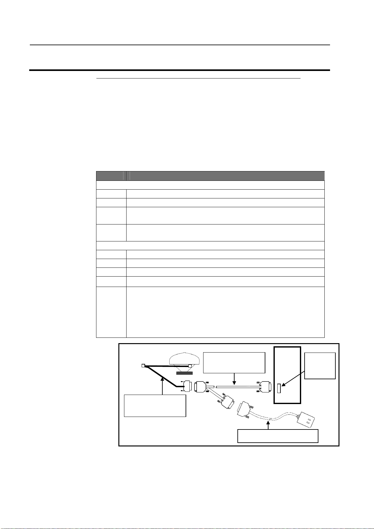
This program is available for download from the Ag Leader web site at
www.agleader.com. To install the program follow the steps below. Refer
to Figure 17 for cable attachments.
Installing Software
Step Action
Cable Attachment
1 Connect the GPS 4100 Lightbar cable to the GPS 4100 receiver.
2 Attach Auxiliary Power Data cable to the GPS 4100 cable
3 Connect the GPS Power Supply to the male connector of the
pigtail on the Auxiliary Power Cable.
4 Connect the remaining single 9-pin connector from the Auxiliary
Power Data Cable to an open COM Port on the PC.
Install Flashloader
1 Install Trimble Flashloader v.2.10 software on the PC.
To start Flashloader program, click on Find Reciever.
2 Click on the check box by UPLOAD NEW FIRMWARE.
3 Select flash code file S171.TNR
4 Click PROCEED to begin the update process, when completed,
click OK.
CAUTION: Any interruption during this process will
leave the GPS inoperable and will require sending the
receiver back for repair.
GPS 4100 Lightbar
Cable
Figure 17. Antenna to PC cable connection
Auxiliary Power
Data Cable
GPS Power Supply Cable
PC
Comm
Port
March 2001
19
Page 22

Installing Software
Installing
AgRemote
Software
AgRemote software requires Windows 95, 98, or 2000. This program is
used to Setup the GPS when you are not using the PF3000 or PF3000
Pro. If you have any questions or problems using this program contact
Technical Support at 515-232-5363.
1. Download the AgRemote software from the Ag Leader web site at
2. In the file download dialog, select "Save this program to disk" and
NOTE: Download will take 5 – 30 minutes depending on your Internet
connection speed.
3. Select My Documents from your computer's desktop.
4. In the My Documents window, double-click AGREMOTE.EXE.
5. Click NEXT and follow the instructions displayed by the Ag
GPS 4100
Ag Leader Technology
www.agleader.com.
specify My Documents on your computer's harddrive.
Remote setup program.
20
March 2001
Page 23

GPS 4100
OMNISTAR
Region
Frequency
RACAL
Region
Frequency
Ag Leader Technology
Commercial Satellite Differential Providers
OmniSTAR Contacts Racal – LandStar Contacts
North America 888-666-4782 North America 1-888-434-7757
Central & South America 1-713-785-5850 Central & South America +1-713-785-5850
Europe 31-70-317 0900 Europe (44)1224 249 700 Extn 7255
Africa 27-11-315 0420 Middle East (9712) 554 817
Australasia 61-8-9322 5295 Africa (27) 21 704 1600
Far East 65-542 5001
Commercial Satellite Frequencies
Satellite Frequencies
Eastern USA 1556.825
Central USA 1554.497
Western USA 1551.489
Europe 1531.230
Australia 1555.255
Indian Ocean 1538.050
Atlantic Ocean 1541.705 & 1541.715
USA East 1553.345
USA Mountain 1554.350
USA West 1556.255
Europe 1531.210
Australia 1555.330
***
March 2001
21
Page 24

Page 25

Product Registration
Ag Leader Technology stands by all new products with a 2-year limited warranty from the warranty
start date. The warranty start date will initially be set to the date on which your product is shipped from
Ag Leader Technology
If you return this registration/warranty card within 30 days of purchasing this product from your dealer,
the warranty start date will be changed to the date that you purchased the product from your dealer.
Leader Technology
Timely product registration will allow you to receive important product bulletins, upgrade information,
and notice regarding product training in your area.
(Click on Product Registration from the Quick Links list on the Ag Leader Home Page.)
Return this sheet in the enclosed postage-paid envelope or by fax.
.
reserves the right to request proof of the date of purchase stated.
Register On-Line at www.agleader.com
OR
515-232-3595 - fax
Ag Leader Technology
2202 South Riverside Drive
P.O. Box 2348
Ames, Iowa 50010
Ag
Name: _______________________________________________________________________________________
Street Address: ______________________________________________________________________________
City, State, ZIP: ______________________________________________________________________________
Phone # (including area code): ________________________________________________________________
Mobile Phone #: ________________________ Fax #: _________________________________________
Email address:________________________________________________________________________________
Ag Leader Dealer:_____________________________________________________________________________
Date Purchased
Monitor Serial #: _______________________ Flow Sensor Serial #: _________________________________
GPS Antenna Serial #:__________________ Elevator Mount Serial #:______________________________
Light Bar Serial #:_________________________ Key Pad Serial #:___________________________________
:_____________________________________________________________________________
Combine Model #: ________________ Combine Serial #: _________________________________________
 Loading...