

Page 1

ADD-ON GPS
3000/3050/3100
INSTALLATION
AND
GENERAL INSTRUCTIONS
June 2001 Rev. 1 3000124
Page 2

2
Page 3

Add-On GPS 3000/3050/3100
Ag Leader Technology
Contents
Important Notices
Before beginning installation of your Add-On GPS 3000/3050/3100,
please take the time to thoroughly read these instructions. Signal
words (CAUTION, IMPORTANT, and NOTE) are provided to draw
attention to information that is important for the safe/correct
installation and operation of this product.
• CAUTION--will alert you to situations that will impact the
physical safety of you or others.
• IMPORTANT—will alert you to the potential for damage to the
product or loss of data.
• NOTE--will provide you with additional information to simplify a
procedure or clarify a process.
After completing installation of the Add-On GPS we recommend that
you place these instructions in the Options Section of your PF3000
Operator’s Manual to prevent their loss.
To receive upgrade/update information of this product you must send
in or fax the Registration Form. Refer to the Registration Form for
address and fax number.
Item Page
Installing Add-On GPS 2
Updating Operating Program 4
Install Window –Mount PF3000 Bracket 5
Antenna Installation 6
Parts, Tools for Antenna Installation 7
Installing the Antenna Bracket 7
Installing the Antenna 8
Routing the Cable to the Cab 9
General Instructions 10
Overview 10
General Information 10
Beacon Selection 10
Satellite Selection 13
Optional WAAS Selection 20
Diagnostic Screen 21
NMEA Messages 24
GPS Output/Input 24
Troubleshooting 25
Parts List 27
Beacon Information 28
WAAS Information 32
Satellite Information 33
June 2001 Rev. 1 3000124
1
Page 4

Installing Add-On GPS
Add-On GPS 3000/3050/3100
Ag Leader Technology
Installing AddOn GPS
Window Mounting
U-bracket
L-bracket with Velcro
The following parts and tools are needed to install the Add-On GPS
3000/3050/3100 in the combine cab or another vehicle:
• Add-On GPS • Phillips screw driver
• Bottom cover plate • Window scraper
• L-bracket with Velcro • Two alcohol swabs
• Connector cable • Clean, unused paper towels
• Mounting U-bracket NOTE: The type of U-bracket will
depend on your installation requirements.
Mounting U-bracket
Add-On GPS
Connector Cable
Perform the following steps to install the GPS in your vehicle:
NOTE: It is recommended that installation of Add-On GPS be done in a
shop environment.
Bottom Cover Plate
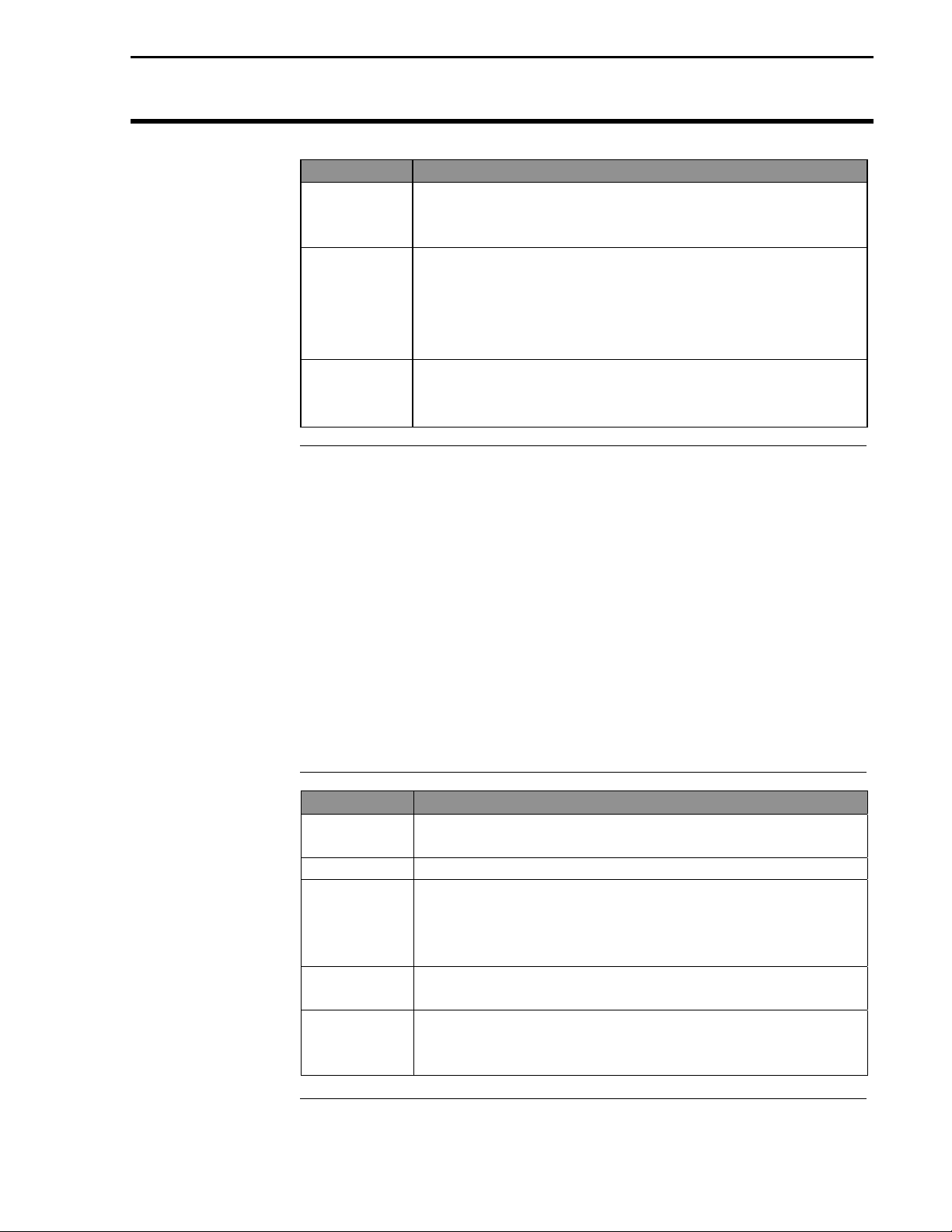
Step Action
1 Remove 25-pin connector from PF3000.
2 Remove PF3000 from mounting bracket.
3 Where the PF3000 ports are located, remove and retain
eight-bottom cover plate screw.
• Four screws in each corner, two screws in the middle and
two screws for the covers on Ports 2 and 3.
4 Remove and discard cover plate.
2
June 2001 Rev. 1 3000124
Page 5

Add-On GPS 3000/3050/3100
Ag Leader Technology
New bottom cover plate
Step Action
5 Position new bottom cover plate on PF3000 (as shown) so
the 25-pin connector and Ports 1, 2 and 3 are aligned with
their slots on the cover plate.
6 Re-install eight bottom screws.
NOTE: Ensure covers for Ports 2 and 3 are re-installed
also.
7 Position Add-On GPS to bottom cover plate so the GPS
and AUX ports are aligned with GPS and AUX slots on
cover plate.
8 Install six additional bottom cover plate screws.
9 Remove and retain top center screw on PF3000.
10 Position L-bracket slot over screw hole with solid part of
bracket with Velcro strip on back of GPS. Squeeze L-
bracket, GPS and PF3000 together and re-install screw.
Installing Add-On GPS
Top center screw
11 Attach connector cable to Port 1 and GPS.
June 2001 Rev. 1 3000124
Connector Cable
3
Page 6
Installing Add-On GPS
Step Action
Add-On GPS 3000/3050/3100
Ag Leader Technology
NOTE: The mounting U-bracket that came with
yourPF3000 will not work with the Add-On GPS, you
must install the new bracket.
12 For U-brackets other than window mount brackets:
• Remove existing U-bracket and retain fasteners.
• Install new U-bracket with fasteners from old bracket
• Attach PF3000 to the U-bracket and attach 25-pin
connector.
13 For window mounted brackets:
• Remove window mounting bracket and discard.
• Completely remove old adhesive from window.
Updating
Operating
Program
The version of operating program that the monitor is using is displayed
when you turn on the PF3000. You MUST have the 3.1 or later
operating program for the PF3000 to use the Add-On GPS3000/3100.
For the Add-On GPS 3050 you must have version 3.13 operating system
installed. To determine if version 3.13 is installed, press the MENU key
until DIAG is displayed. Press the SYSTEM key. Look on the Program
version line to determine the current program.
If you do not have the 3.1 or 3.13 or later version, contact Ag Leader
Technology at 515-232-5363 to obtain an update.
Perform the following steps to install the new operating program:
Step Action
1 Using a computer card reader, copy the file “upgrade.pld”
to the memory card. Delete all other files off the card.
2 Install the card in the monitor and turn on the monitor.
3 The monitor will automatically detect a new operating
program on the card. The monitor will display the version
number of the current program and new program. Press
the ACCEPT key to install the new version.
4 The monitor will erase the old program and install the
new program.
5 Check some of the field and load information and settings
to double check that the new programs is operating
correctly
4
June 2001 Rev. 1 3000124
Page 7

Add-On GPS 3000/3050/3100
Ag Leader Technology
Installing Add-On GPS
Install Window
Mount PF3000
Bracket
The window mount bracket for the Add-On GPS 3000/3050/3100, will
provide a very secure mounting for the PF3000 ONLY IF the window
glass surface is chemically cleaned. Some installers have reported
problems with the adhesive strips coming off the glass. This is a
problem only if the glass was not properly cleaned and dry. Follow
Steps 1 through 6 to ensure the glass is clean and dry for installation:
Step Action
1 In humid conditions where moisture may condense on the
glass, run the air conditioner on a medium to warm
temperature setting to fill the cab with dry air. Run air
conditioner until the glass is dry.
2 Determine the position for the window bracket on the
window.
3 Using a clean, unused paper towel, wipe off an area of the
window larger than where you have determined is proper
position for the bracket.
4 When the glass is visually clean, use one of the provided
alcohol swabs to wipe a slightly smaller area.
5 Before the alcohol dries, use a clean, unused paper towel
to wipe off the area.
6 Repeat Steps 4 and 5, so the glass has been cleaned twice
with alcohol swabs.
7 Carefully remove the peel-off strips from the adhesive
strips on the back of the PF3000. Do not touch the
adhesive surface of the strips.
8
9 When bracket is properly aligned, push the bracket firmly
10 Use the heel of your hand or fist to gently pound on the
11 Attach PF 3000 to the bracket and attach 25-pin
IMPORTANT: Once the adhesive strip contacts the
glass the bracket cannot be moved without damage to
adhesive strips.
Without touching the strips to the glass, align the window
bracket with the position you determined in Step 2.
against the glass to bond the adhesive strips.
bracket to ensure that the adhesive is fully bonded to the
glass.
connector.
NOTE: The adhesive strips cannot be re-installed if they
have pulled off the glass. Call Ag Leader Technology
(515-232-5363) if you need new adhesive.
***
June 2001 Rev. 1 3000124
5
Page 8
Antenna Installation
Add-On GPS 3000/3050/3100
Ag Leader Technology
Antenna
Installation
Before mounting the Add-On GPS 3000/3050/3100 on your vehicle, the
user should test the system in the planned installation location. Turn on
all accessories or features of the vehicle that use electrical power,
examples being lights, air-conditioners, etc. In order to determine your
signal-to-noise-ratio (SNR) while installing your antenna, you must be on
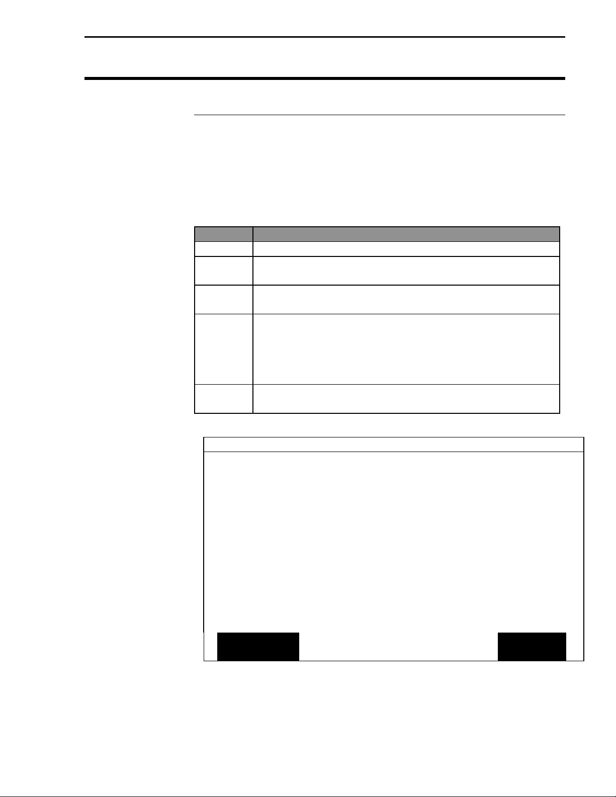
the GPS Diagnostic screen of the PF3000. To view this screen:
Step Action
1 Plug antenna jack into GPS unit.
2 Press the Menu key until DIAG is displayed and press DIAG
Key.
3 Press GPS key. NOTE: An example of the GPS Diagnostic
screen (Figure 1) is shown below.
4 If the SNR drops below 6 or is lost completely, move the
antenna to a location where the signal is not as affected by
the interference. Moving the antenna horizontally or
vertically between 1 to 3 ft will usually eliminate the
problem.
5 Once you have completed positioning your antenna push
EXIT key.
GPS DIAGNOSTICS
UTC TIME 00:00:00
Latitude 0000.0000 S
Longitude 0000.0000 E
Elevation 0 ft
GPS speed 0.0 MPH
Number of satellites 0
Differential Status OFF
Beacon/Sat. Frequency 0.000
Differential SNR 0.0
HDOP/PDOP 0.00/0.00
Antenna/Rcvr Voltage 5.00/13.73
ADD-ON
GPS
Figure 1. GPS Diagnostic screen
FORMAT
CARD
COPY TO
CARD
EXIT
6
June 2001 Rev. 1 3000124
Page 9

Add-On GPS 3000/3050/3100
Ag Leader Technology
Antenna Installation
Parts, Tools for
Antenna
Installation
Installing the
Antenna Bracket
The following parts and tools are needed to install the antenna and its
bracket:
• 5/16 in. self tapping bolts • L-bracket
or 5/16 in. bolts with serrated nuts • Antenna
• ¼ in. drill bit for thin metal • Marker
or 9/32 in. for thicker metal • Punch
• 15 ft coaxial cable • Hand drill
• Three white cable tie-downs
with self tapping screws
• Three white cable tie-downs
Follow these steps to attach the L-bracket to the grain tank or bin
extension (whichever is on your combine).
Step Action
1 Center the L-bracket on the combine making sure that it is
in the center of header. If you are installing on a vehicle
other than a combine, you may or may not be able to use
the L-bracket. Make sure, though, that the antenna is in the
center of the swath.
2 Place the top surface of the bracket about ¼ in. above the
top of the highest metal surface of the vehicle so that the
antenna is the highest point of the vehicle and can slide off
if struck.
3 After you site this position, place the L-bracket against the
metal surface, mark and punch the places you will be
drilling.
4
Drill the holes in the surface and attach brackets as
follows:
If the metal is … Then use a…
Thin ¼ in. drill bit and 5/16 in.
bolts with serrated nuts.
Thick (1/8 in. or more) 9/32 in. bit and self-tapping
bolt.
June 2001 Rev. 1 3000124
7
Page 10

Installing Add-On GPS
Add-On GPS 3000/3050/3100
Ag Leader Technology
Installing
Antenna
Follow these steps to install the antenna:
Step Action
1 Center the antenna on the top the top surface of the
bracket, placing the antenna so the cable connector is
pointing towards the right side of combine or vehicle.
2 Attach the 15 ft cable to antenna, connecting the end with
the plug to antenna.
3 Attach a white cable tie-down to metal surface 1 or 2 ft
below and 6 in. to right of the L-bracket.
NOTE: you may need to increase the above distances,
depending on the type of grain extension you are using.
4 Place another white tie-down 3 to 5 ft. to the right of the
first tie-down.
5 Use a cable tie and attach the coaxial cable to the first
white tie-down leaving some slack in cable between
antenna connection and tie down to allow for strain relief if
the antenna is knocked off the L-bracket.
6 Use another cable tie to attach the cable to the second tie-
down.
7 Route cable to cab using cable tie-downs to secure cable.
8
June 2001 Rev. 1 3000124
Page 11

Add-On GPS 3000/3050/3100
Ag Leader Technology
Antenna Instructions
Routing the Cable
to the Cab
You will need the following parts and tools to route the coaxial cable into
the combine:
• Bulkhead connector (threaded on both ends)
• ½ in. drill bit
• Power drill
Follow these steps to route cable to the cab:
Step Action
1 Find a place on the right side or bottom of the cab to route
coaxial cable into cab (the point of entry is up to you).
IMPORTANT: Do NOT route cable through a door or
window because this will crimp the cable and ruin it.
2 Find a sit to drill where you will not drill into any cabling
or hoes; then drill a hole with the 1/2 in. bit.
NOTE: Make sure before you drill that:
•
The coaxial cable will reach to the site you have
chosen.
•
That you do not bend the cable at a 90-degree
angle.
3 Thread bulkhead connector through hole, so that the
threaded end to which you attach the lock washer and jam
nut is inside cab.
NOTE: For JD9000 series combines, a rubber grommet is
included to mount the bulkhead connector through cab
wall plate. Use auxiliary hole in the plate or drill a new
hole if the auxiliary hole is in use.
4 Attach the coaxial cable from the antenna to the outside
end of the connector.
***
June 2001 Rev. 1 3000124
9
Page 12

General Instructions
Add-On GPS 3000/3050/3100
Ag Leader Technology
Overview
General
Information
The Add-On GPS 3000/3050/3100 requires no initial setup to begin
fieldwork. The PF3000 will display a “D” or “G” on the top right hand
corner of the display to indicate a GPS signal. A “D” indicates that you
have a differential signal. A “G” indicates that you have a GPS signal
and your GPS receiver is tracking four or more satellites. A lower case
“g” indicates that you have a GPS signal but your GPS receiver is
tracking only three satellites. Your GPS receiver must track four or more
satellites to get an elevation reading. You may wish to use the GPS to
show your ground speed, which requires changing the ground speed
sensor settings. Refer to Primary and Secondary Speed Sensor under
Vehicle Setup in the PF3000 Operator’s manual for instructions.
NOTE: WAAS is an optional feature now available for use with
the Add-On GPS. Contact Ag Leader Technical Support at 515232-5363 for more information on this capability.
The following provides information to change factory settings on the
Add-On GPS 3000/3050/3100:
Beacon Selection
The settings for beacon selection are Auto range, Auto Power and
Manual.
• Auto Range: This is the default setting. In this setting the receiver
keeps a record of the closest three beacons within the receivers
range. It then selects a beacon based on the ranking of the beacon
in memory.
• Auto Power: The receiver keeps a record of the three strongest
beacons in its range. It then selects a beacon based on the ranking
of the available beacons.
• Manual: Allows you to input frequencies for two beacons.
To change Beacon Selection complete the following steps:
Step Action
1 Press Menu key on PF3000 until SETUP is displayed and
press SETUP.
2 Press bottom left or right arrow key until GPS is
displayed and press GPS key.
10
June 2001 Rev. 1 3000124
Page 13

Add-On GPS 3000/3050/3100
Ag Leader Technology
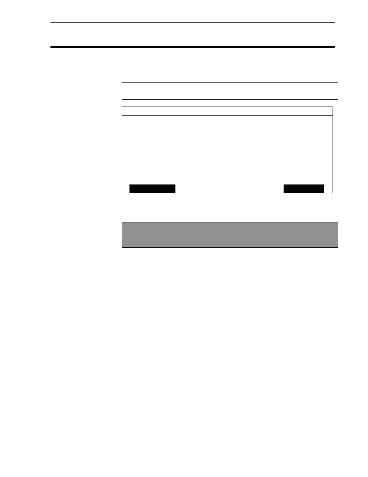
GPS SETUP
EDIT EXIT
Figure 2. GPS SETUP Screen
General Instructions
NMEA MESSAGE
GPS PORT CONFIGURATION
BEACON DIFFERNTIAL
SATELLITE DIFFERNTIAL
LIGHTBAR
GUIDANCE
3 From the GPS SETUP screen (Figure 2) scroll down to
Beacon Mode and press EDIT key. Use up or down
arrow keys to set mode.
BEACON SETUP
Mode: Auto Power
Channel 0 Frequency AUTO
Channel 1 Frequency AUTO
ACCEPT EXIT
Figure 3. Auto Power Setting
4 After setting Auto Power (Figure 3) mode, push
ACCEPT key and then EXIT.
June 2001 Rev. 1 3000124
11
Page 14

General Instructions
Add-On GPS 3000/3050/3100
Ag Leader Technology
BEACON SETUP
Mode: Manual
Channel 0 Frequency 300.0
Channel 1 Frequency 300.0
ACCEPT EXIT
Figure 4. Manual Setting
5 If you are setting to Manual (Figure 4) push ACCEPT key then
use down arrow key to scroll to Channel 0 Frequency and
press EDIT key. Use the up or down arrow key to set desired
frequency and press ACCEPT key. Scroll down to Channel 1
Frequency and press EDIT key. Use up or down arrow keys to
set desired frequency and press ACCEPT key.
Age of Differential
6 Press the EXIT key two times to return to operating screen.
Age of Differential is the delay setting used to continue logging data if
Beacon or Satellite reception is lost.
Step
1 At the GPS SETUP screen (Figure 5) scroll down to Satellite
Differential Mode with down arrow key and press EDIT.
2 Scroll down to Age of Differential and press EDIT.
3 Use the UP or DOWN ARROW keys to set the time.
NOTE: If you are using Trimble firmware below
version 1.50 you will be able to set the delay up to 90
seconds. If you are using version 1.50 or greater the
value may be set as high as 250 seconds.
Action
12
June 2001 Rev. 1 3000124
Page 15

Add-On GPS 3000/3050/3100
Ag Leader Technology
SATELLITE DIFFERENTIAL SETUP
Differential Source Beacon
Age of Differential 90 seconds
EDIT EXIT
Figure 5. Setting Age of Differential for Add-On GPS 3000 and 3050
General Instructions
Satellite Selection
This option is available on the Add-On GPS 3100 only. If you will be
using the satellite differential option then do the following depending on
which service provider you select.
Step Action
1 Press Menu key on PF3000 until SETUP is displayed,
press SETUP key.
2 Press bottom left or right arrow key until GPS is
displayed and press GPS key.
GPS SETUP
NMEA MESSAGE
GPS PORT CONFIGURATION
BEACON DIFFERNTIAL
SATELLITE DIFFERNTIAL
LIGHTBAR
GUIDANCE
EDIT EXIT
Figure 6. GPS SETUP Screen
June 2001 Rev. 1 3000124
13
Page 16
General Instructions
Add-On GPS 3000/3050/3100
Ag Leader Technology
3 At the GPS SETUP screen (Figure 6) scroll down to Satellite
Differential Mode with down arrow key and press EDIT.
SATELLITE DIFFERENTIAL SETUP
Differential Source Satellite
Differential Provider Omnistar
Satellite Frequency 0000.0000
Satellite Baud Rate 0000
Provider User Code 0
OMNISTAR Code 000000000000000000000000
Age of Differential 90 seconds
EDIT EXIT
Figure 7. Satellite Differential Setup Screen
If you
will be
using…
Omnistar At SATELLITE DIFFERENTIAL SETUP screen (Figure 7)
Then…
Differential Source will be highlighted, press EDIT key and
use up or down arrow key until Satellite is displayed and
press ACCEPT key. Scroll down to Differential Provider
and press EDIT key. Use the up or down arrow key until
Omnistar is displayed and press ACCEPT key. Scroll down
to Satellite Frequency and press EDIT key. Use the up or
down arrow key to select your region (Figure 78 and press
ACCEPT key. Use the up or down arrow key to select your
region and press ACCEPT key. If you will be using a
custom frequency (Figure 9) with this provider, scroll down
to Custom (1) and push EDIT NAME key. Use the
up/down and left/right arrow keys to name this frequency.
Push EDIT VALUE key and use the up/down and left/right
arrow keys to enter the frequency. Push ACCEPT key.
Your customized frequency should appear as the Satellite
Frequency.
14
June 2001 Rev. 1 3000124
Page 17

Add-On GPS 3000/3050/3100
Ag Leader Technology
SATELLITE DIFFERENTIAL SETUP
Omnistar Satellite Beacon Frequencies:
Eastern USA 1556.825
Central USA 1554.497
Western USA (1) 1551.429
Western USA (2) 1551.489
Europe 1531.230
South America (1) 1541.705
South America (2) 1541.715
Custom (1) 0000.0
Custom (2) 0000.0
EDIT EXIT
General Instructions
Australia 1558.510
Figure 8. Region Frequencies Screen
SATELLITE DIFFERENTIAL SETUP
Omnistar Satellite Beacon Frequencies:
Eastern USA 1556.825
Central USA 1554.497
Western USA (1) 1551.429
Western USA (2) 1551.489
Australia 1558.510
Europe 1531.230
South America (1) 1541.705
South America (2) 1541.715
Custom (1) 0000.0
Custom (2) 0000.0
EDIT EDIT
NAME
EDIT
VALUE
EXIT
Figure 9. Custom Frequency Screen
June 2001 Rev. 1 3000124
15
Page 18
General Instructions
Add-On GPS 3000/3050/3100
Ag Leader Technology
Call the Omnistar subscription number (713-785-5850 in
the USA) and give them the number to the right of the GPS
serial number. Omnistar will then give you a 24-digit code.
Key the code into the right of Omnistar Code (See Figure
10) using up and down arrow keys. Once the code is
entered, press ACCEPT key to send the code to the unit.
Now press EXIT key to return to GPS SETUP screen, press
exit key to return to operating screen. After 30 minutes, the
receiver should start receiving corrections and display a “D”
in the upper right hand corner of the PF3000.
SATELLITE DIFFERENTIAL SETUP
Differential Source Satellite
Differential Provider Omnistar
Satellite Frequency 1554.497000
Satellite Baud Rate 1200
Provider User Code 3466
OMNISTAR Code 000000000000000000000000
Age of Differential 90 seconds
Age of Differential
ACCEPT CANCEL
Figure 10.
Age of Differential is the delay setting used to continue logging data if
Beacon or Satellite reception is lost.
Step
1 Scroll down to Age of Differential and press EDIT. See
Figure 10.
2 Use the UP or DOWN ARROW keys to set the time.
NOTE: If you are using Trimble firmware below
version 1.50 you will be able to set the delay up to 90
seconds. If you are using version 1.50 or greater the
value may be set as high as 250 seconds.
Action
16
June 2001 Rev. 1 3000124
Page 19

Add-On GPS 3000/3050/3100
Ag Leader Technology
General Instructions
If you will
be using
RACAL…
RACAL At SATELLITE DIFFERENTIAL SETUP screen (See
Then…
Figure 7) Differential Source will be highlighted press
EDIT key and use up or down arrow key until Satellite is
displayed and press ACCEPT key. Scroll down to
Differential Provider and press EDIT key. Use the up or
down arrow key until RACAL is displayed and press
ACCEPT key. Scroll down to Satellite Frequency and press
EDIT key. Use the up or down arrow key to select your
region (Figure 11) and press ACCEPT key. Use the up or
down arrow key to select your region and press ACCEPT
key. If you will be using a custom frequency (Figure 12)
with this provider, scroll down to Custom (1) and push
EDIT NAME key. Use the up/down and left/right arrow
keys to name this frequency. Push EDIT VALUE key and
use the up/down and left/right arrow keys to enter the
frequency. Push ACCEPT key. Your customized
frequency should appear as the Satellite Frequency.
SATELLITE DIFFERENTIAL SETUP
RACAL Satellite Beacon Frequencies:
North American East 1553.345
North American Mtn 1554.350
North American West 1556.225
Australia 1553.525
Europe 1531.210
South Africa 1552.640
Custom (1) 0000.0
Custom (2) 0000.0
Custom (3) 0000.0
Custom (4) 0000.0
ACCEPT EXIT
Figure 11. Region Frequencies Screen
June 2001 Rev. 1 3000124
17
Page 20

General Instructions
Add-On GPS 3000/3050/3100
Ag Leader Technology
SATELLITE DIFFERENTIAL SETUP
RACAL Satellite Beacon Frequencies:
North American East 1553.345
North American Mtn 1554.350
North American West 1556.225
Australia 1553.525
Europe 1531.210
South Africa 1552.640
Custom (1) 0000.0
Custom (2) 0000.0
Custom (3) 0000.0
Custom (4) 0000.0
ACCEPT EDIT
NAME
Figure 12.Custom Frequency Screen
Call the RACAL subscription number (713-784-4482 in
the USA) and give them the number to the right of the
GPS serial number. RACAL will activate a code for the
serial number that was given. After the serial number is
called in, press the EXIT key (Figure 13) to return to
operating screen. A “D” should appear in the upper right
hand corner of the PF3000. Within 15 to 30 minutes the
receiver should start receiving corrections from RACAL.
SATELLITE DIFFERENTIAL SETUP
Differential Source Satellite
Differential Provider RACAL
Satellite Frequency 1553.345000
Satellite Baud Rate 1200
Provider User Code 8111
OMNISTAR Code 000000000000000000000000
Age of Differential 90 seconds
EDIT
VALUE
EXIT
18
SUMMARY CAL SETUP DIAG
Figure 13.
June 2001 Rev. 1 3000124
Page 21

Add-On GPS 3000/3050/3100
Ag Leader Technology
General Instructions
Age of Differential
Age of Differential is the delay setting used to continue logging data if
Beacon or Satellite reception is lost.
Step
1 Scroll down to Age of Differential and press EDIT. See
Figure 13.
2 Use the UP or DOWN ARROW keys to set the time.
NOTE: If you are using Trimble firmware below
version 1.50 you will be able to set the delay up to 90
seconds. If you are using version 1.50 or greater the
value may be set as high as 250 seconds.
Action
June 2001 Rev. 1 3000124
19
Page 22

General Instructions
Add-On GPS 3000/3050/3100
Ag Leader Technology
Optional WAAS
Selection
NOTE: WAAS is an optional feature now available for use with
the Add-On GPS. Contact Ag Leader Technical Support at 515232-5363 for more information on this capability.
NOTE: Ag Leader Technology cannot guarantee the availability
or performance of the WAAS signal or that it will continue to be
free of charge.
If you are going to use the Optional WAAS differential option complete
the following:
Step Action
1 Press Menu key on PF3000 until SETUP is displayed, press
SETUP key.
2 Press bottom left or right arrow key until GPS is displayed and
press GPS key. You should now see the screen shown in
Figure 14.
GPS SETUP
NMEA MESSAGE
GPS PORT CONFIGURATION
BEACON DIFFERENTIAL
SATELLITE DIFFERENTIAL
LIGHTBAR
GUIDANCE
20
EDIT EXIT
Figure 14. GPS SETUP Screen
Step Action
3 At the GPS SETUP screen (Figure 14) scroll down to Satellite
Differential Mode with down arrow key and press EDIT. You
should now see the screen shown in Figure 15.
June 2001 Rev. 1 3000124
Page 23

Add-On GPS 3000/3050/3100
Ag Leader Technology
SATELLITE DIFFERENTIAL SETUP
Differential Source WAAS
Differential Provider
Satellite Frequency 0000.0000
Satellite Baud Rate 0000
Provider User Code 0
OMNISTAR Code 000000000000000000000000
Subscription Expiration 00/00/0000
Ag of Differential 90 seconds
EDIT EXIT
Figure 15. Satellite Differential Setup screen.
General Instructions
Diagnostic Screen
The diagnostic screen (Figure 16) provides troubleshooting and
reference information for the Add-On GPS. Provided are
definitions of screen terms.
GPS DIAGNOSTICS
UTC TIME 00:00:00
Latitude 0000.0000 S
Longitude 0000.0000 E
Elevation 0 ft
GPS speed 0.0 MPH
Number of satellites 0
Differential Status OFF
Beacon/Sat. Frequency 0.000
Differential SNR 0.0
HDOP/PDOP 0.00/0.00
Antenna/Rcvr Voltage 5.00/13.73
ADD-ON
GPS
Figure 16. GPS Diagnostics Screen
FORMAT
CARD
COPY TO
CARD
EXIT
June 2001 Rev. 1 3000124
21
Page 24

General Instructions
Figure 17. Add-On GPS Diagnostic Screen
Add-On GPS 3000/3050/3100
Ag Leader Technology
ADD-ON GPS DIAGNOSTICS DG
Product Id AL 9001
Trimble Firmware Version 1.50
Firmware Date 03/15/01
Receiver Serial Number 0224004738
PV Filter Status ON
Everest Multipath OFF
Fast Update Rate OFF
Guidance Status OFF
EXIT
22
June 2001 Rev. 1 3000124
Page 25

Add-On GPS 3000/3050/3100
Ag Leader Technology
UTC TIME: Greenwich Mean Time (GMT), the current time
Greenwich, England
NOTE: The US Coast Guard may also refer to GMT as “ZULU”.
Latitude: Current latitude of the receiver in degrees-minutes.
fractional minutes.
Longitude: Current longitude of the receiver in degreeminutes.fraction minutes.
Elevation: Current elevation of the receiver in feet.
GPS Speed: Current speed of the receiver in miles-per-hour.
Number of Satellites: Indicates the number of satellites the unit
is using. The unit can track a maximum of twelve satellites.
Differential Status: Indicates ON or OFF, telling you whether a
differential signal is being used.
Beacon/Satellite Frequency: Indicates the frequency of the
differential source that the GPS is using of the location of the
differential source.
Differential SNR: Signal-to-noise-ration (SNR) indicates the
strength of the correction signal in relation to the amount of
background noise that can interfere with signal reception. A good
SNR is 10 to 18.
HDOP/PDOP: Horizontal Dilution of Precision (HDOP)
indicates the quality of the horizontal GPS position. Position
Dilution of Precision (PDOP) is a unitless measure indicating
when the satellite geometry can provide the most accurate results.
When satellites are spread around the sky, the PDOP value is low
and the computed position is more accurate. When satellites are
grouped close together the PDOP is high and the positions are
less accurate.
Antenna/Receiver Voltage: An antenna/receiver voltage of 5 or
higher indicates that the antenna is not plugged into the GPS
receiver. When the antenna is properly installed, the voltage
should read .5 or less.
General Instructions
June 2001 Rev. 1 3000124
23
Page 26

General Instructions
Add-On GPS 3000/3050/3100
Ag Leader Technology
NMEA Messages
The Add-On GPS unit uses Trimble TSIP to provide position
information to the PF3000. This means that NMEA messages (Figure
18) do not need to be set and will not be displayed on the NMEA
diagnostic screen.
NMEA MESSAGES
GGA ON
GLL OFF
VTG ON
GSV OFF
GSA OFF
ZDA OFF
ALM OFF
RMC OFF
MSS ON
EDIT EXIT
Figure 18. NMEA Messages Screen
GPS
Output/Input
The GPS Output/Input screen (Figure 19) requires no adjustment
at this time. This screen will be used for future options for the
AUX Port of the GPS.
GPS OUTPUT/INPUT SETUP
Output rate 1Hz
Port AUX
Output baud rate 4800
Output type NMEA
Input baud rate 9600
Input type TSIP
SUMMARY CAL SETUP DIAG
Figure 19. GPS Output/Input Setup Screen
***
24
June 2001 Rev. 1 3000124
Page 27

Add-On GPS 3000/3050/3100
Ag Leader Technology
Troubleshooting
Troubleshooting
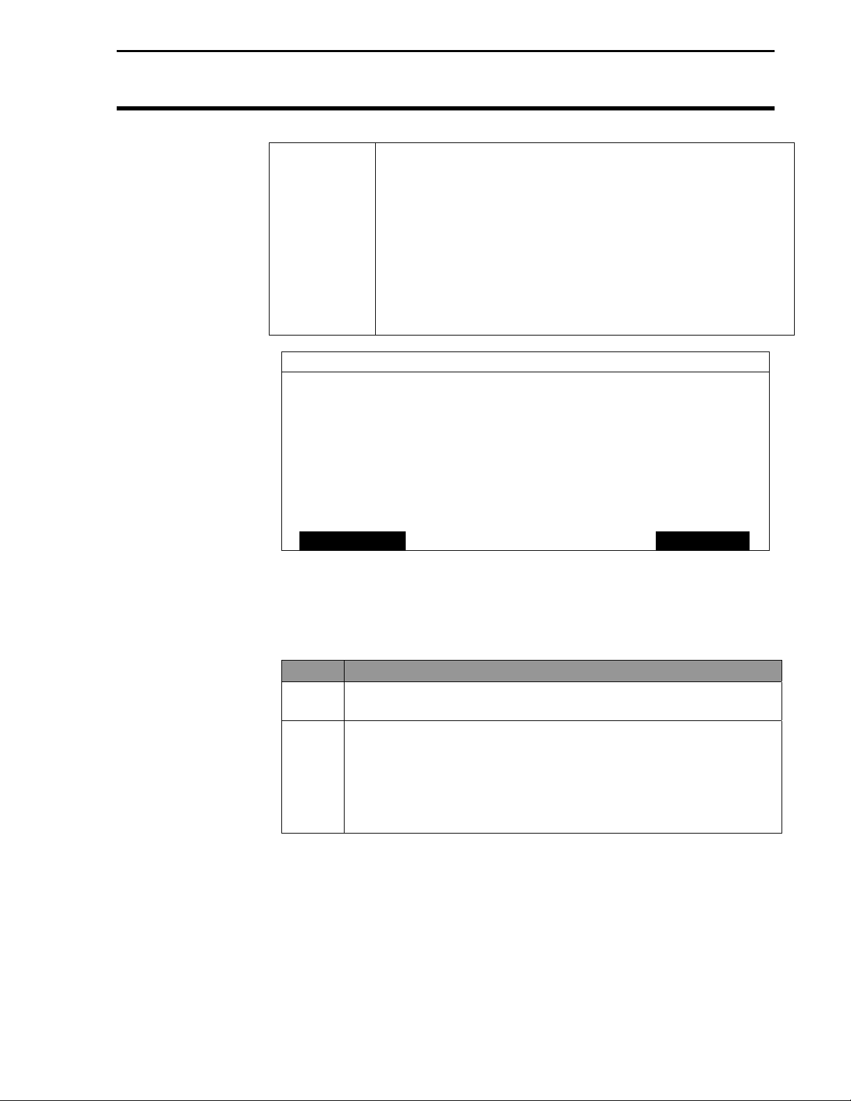
Problem Cause Solution
Differential correction
fades in and out
The Add-On GPS
3000/3050/3100 will
not stay locked on a
beacon and switches
erratically back and
forth from one beacon
to another.
The following is a list of problems that you may encounter with the AddOn GPS 3000/3050/3100 and suggestions for troubleshooting. If you have
a problem with the system, please review the list before calling Ag Leader
Technology. If your troubleshooting does not solve the problem, please
call Technical Support at Ag Leader Technology (515-232-5363).
• A strong
thunderstorm or
disturbance is near
or located between
antenna and
differential source.
• You are in a fringe
area for reception.
• Interference from
your vehicle or
machinery.
• Either one or more
of the beacons has
an unhealthy or
unmonitored status
or there is a large
amount of
interference in the
signal from a
certain beacon.
• The thunderstorm must pass or
decrease in intensity.
• Determine if there are
thunderstorms in the vicinity or
call Ag Leader Technology to see
whether the beacon near you is
operational.
• Move the antenna to a position
where it is not as strongly
affected by the interference.
• Adjust your Age of Differential to
90 seconds or 250 seconds
depending on your firmware.
• Press the Menu key until SETUP
is displayed. Press SETUP key.
GPS is displayed. Press GPS key.
Scroll down to Beacon Mode, the
user has two options (See Beacon
Selection in General Information
section):
• Select Auto power
• Select Manual mode. Manual
mode is the best choice in this
case if the user has a beacon that
they know is providing a good
signal.
• Press the EXIT key. The display
returns to the startup screen and
within about one minute or less
the unit will lock on to the
selected frequency.
June 2001 Rev. 1 3000124
25
Page 28

Troubleshooting
Problem Cause Solution
When the Add-On
GPS is used on a
vehicle, such as a
truck or car, the SNR
for the beacon being
used is very low or the
unit cannot lock on a
differential correction.
Antenna voltage
indicates 5 volts or
more.
Near dusk the Add-On
GPS loses differential
or switches erratically
from beacon to beacon
for about one halfhour.
When the lights on a
vehicle, specifically
the combine, are
turned on the SNR
value drops
considerably or
differential correction
is lost completely
Monitor dims when
using external power
source for PF3000.
After powering up the
PF3000 with Add-On
GPS you are unable to
enter the GPS setup
screen.
Add-On GPS 3000/3050/3100
• Electrical noise
generated by the
vehicles electrical
system.
• Loose connection.
• Antenna is
malfunctioning.
• Changes in
atmospheric
properties near
dusk affect signal
quality and can
induce skipping of
signals that usually
can be received.
• The load on he
electrical system
has increased and
noise has been
introduced into the
system.
• External power
source for PF3000
does not provide
enough power.
• PF3000 did not
properly detect the
Add-On GPS.
Ag Leader Technology
• Move the antenna to a location
that is not affected.
• Use a line filter on main power to
unit.
• Attach a 6 inch or 12 inch square
sheet of metal to the vehicle for
mounting the antenna on to aid in
blocking interference.
• Check bulkhead connection.
• Check antenna connections.
• Set unit in Manual Mode on the
BEACON OPTIONS screen to
help keep the correction the user
receivers more consistent. This is
an operational characteristic that
can not be eliminated.
• Check the alternator to see
whether it is in satisfactory
condition and whether its capacity
is correct for the loads it must
carry.
• New external power source is
available to support Add-On GPS
to PF3000.
• Power the PF3000 down and then
restart.
• Ensure the connector cable
between the PF300 and GPS is
properly connected.
• If these actions fail, please call
Technical Support at 515-232-
5363.
26
June 2001 Rev. 1 3000124
Page 29

Add-On GPS 3000/3050/3100
Ag Leader Technology
Parts List—Add-On GPS 3000/3050/3100
Part Name/Description Part Number Quantity
Installation/Instructions 1
GPS receiver unit
Model3000
Model3050
Model3100
Pivot Bracket
Bottom Cover Plate 3000118 1
Antenna assembly
GPS2000 or,
GPS2100
Antenna Bracket (L-shape) 2000161 1
L-Bracket with Velcro 3000125 1
Add-On GPS cable kit 3000501 1
Antenna Installation Kit
5/16 in. self tapping bolts
5/16 in. hex bolts
5/16 in. serrated nuts
White cable tie down
#10 self tapping screw
Bulkhead connector
Grommet--1/2 in. inside
diameter
Cab/Cable Kit
Cable ties—6 in.
Cable ties—15 in.
Alcohol swabs
Cable clamps
3000120
3000138
3000121
2000162
2000179
2000192
2001310-1 1
1
1
1
2
1
1
4
4
4
3
3
1
1
1
2
Parts List
***
June 2001 Rev. 1 3000124
27
Page 30

Beacon Information
Add-On GPS 3000/3050/3100
Ag Leader Technology
Beacon
Information
Location ID Baud Rate Frequency
Brunswick, ME 800 100 316
Cape Canaveral, FL 809 100 289
Cape Henlopen, DE 805 200 298
Reedy Point, DE 870 200 309
Alexandria, VA 820 100 305
Cape Henry, VA 806 100 289
C2Cen, Portsmouth, VA 821 200 313
Charleston, SC 808 100 298
Diver, VA 806 100 289
Chatham, MA 802 200 325
Fort Macon, NC 807 100 294
New Bern, NC 771 100 294
Miami, FL 810 100 322
Monriches, NY 803 100 293
Penobscot, ME 799 200 290
Portsmouth, NH 801 100 288
Hudson Falls, NY 844 200 324
Annapolis, MD** 847 200 301
Savannah, GA 818 100 319
Macon, GA 822 200 301
Sandy Hook, NJ 804 200 286
In the USA, call 1-703-313-5900 for Coast Guard GPS support.
Or use the web site at
operation status of the beacon stations.
Atlantic Coast
http://www.navcen.uscg.mil/gps/status/txt for the
Gulf Coast
Location ID Baud Rate Frequency
Aransas Pass, TX 816 100 304
Egmont Key. FL 812 200 312
Galveston, TX 815 100 296
Key West, FL 811 100 286
Mobile Point., AL 813 100 300
Millers Ferry, AL 865 200 320
English Turn , LA 814 200 293
Puerto Rico 818 200 295
*Engineering Test Site (Not fully operational, only in test mode)
**Under Construction
28
June 2001 Rev. 1 3000124
Page 31

Add-On GPS 3000/30503100
Ag Leader Technology
Great Lakes
Location ID Baud Rate Frequency
Cheboygan, MI 836 200 292
Detroit, MI 838 200 319
Milwaukee, WI 833 100 297
Neebish Island, MI 835 200 309
Saginaw Bay, MI 837 100 301
Sturgeon Bay, MI 832 100 322
Upper Keweenaw, MI 831 100 298
Whitefish Pt., MI 834 100 318
Wisconsin Pt., WI 830 100 296
Youngstown, NY 839 100 322
Pacific Coast
Location ID Baud Rate Frequency
Chico, CA 878 100 318
Cape Mendocino, CA 885 100 292
Pigeon Point, CA 883 100 287
Point Arguello. CA 882 100 321
Point Blunt, CA 884 200 310
Point Loma, CA 881 100 302
Fort Stevens, OR 886 100 287
Appleton, WA 871 100 300
Robinson Point, WA 887 200 323
Spokane, WA* 848 100 316
Whidbey Is., WA 888 100 302
Beacon Information
Alaska
Location ID Baud Rate Frequency
Annette Island, AK 889 100 323
Biorka Island, AK* 821 200 313
Cape Hinchenbrook 894 100 292
Cold Bay, AK 898 100 289
Gustavus, AK 892 100 288
Kenai, AK 896 100 310
Kodiak, AK 897 100 313
Potato Point, AK 895 100 298
*Engineering Test Site (Not fully operational, only in test mode)
June 2001 Rev. 1 3000124
29
Page 32

Beacon Information
Add-On GPS 3000/3050/3100
Ag Leader Technology
Hawaii/Puerto Rico
Location ID Baud Rate Frequency
Isabella, Puerto Rico 817 200 295
Kokole Point, HI 880 200 300
Upolo Point, HI 897 100 286
Inland
Location ID Baud Rate Frequency
St. Louis, MO 862 200 322
Kansas City, MO 867 200 305
Vicksburg, MS 860 200 313
Memphis, TN 861 200 310
Hartsville, TN 858 100 317
St. Paul, MN 864 200 317
Sillisaw, OK 866 200 299
Millers Ferry, AL 865 200 320
Billings, MT 874 100 313
Clark, SD 850 100 309
Louisville, KY 869 200 290
Rock Island, IL 863 200 311
Omaha, NE 868 200 298
Whitney, NE 859 200 310
Flagstaff, AZ 876 100 319
Kirkland, NM 845 100 291
Polson, MT* 849 100 287
Summerfield, TX 823 100 318
*Engineering Test Site (Not fully operational, only in test mode)
30
June 2001 Rev. 1 3000124
Page 33

Add-On GPS 3000/3050/3100
Beacon Information
Ag Leader Technology
Canada
Location Baud Rate Frequency
Alert Bay, BC 200 309
Amphitrite Point, BC 200 315
Richmond, BC 200 307
Sandspit, BC 200 300
Canada
Location Baud Rate Frequency
Partridge Island, NB 200 295
Point Escuminiac, NB 200 319
Cape Ray, NF 200 290
Cape Race, NF 200 288
Cape Norman, NF 200 310
Fox Island, NS 200 307
Western Head, NS 200 312
Cardinal. ON 200 306
Wiarton, ON 200 286
Lauzon, PQ 200 309
Moisie, PQ 200 313
Riviere du Loup, PQ 200 300
St. Jean sur Richelieu, PQ 200 296
Trois Rivieres, PQ 200 321
June 2001 Rev. 1 3000124
31
Page 34

WAAS Information
NOTE: Ag Leader Technology cannot guarantee the availability or
performance of the WAAS signal or that it will continue to be free of
charge.
AOR-W (PRN 122) POR (PRN 134)
Add-On GPS 3000/3050/3100
Ag Leader Technology
WAAS
32
June 2001 Rev. 1 3000124
Page 35

Add-On GPS 3000/3050/3100
Ag Leader Technology
OMNISTAR
Region Frequency
Eastern USA 1556.825
Central USA 1554.497
Western USA 1551.489
Europe 1531.230
Australia 1555.255
Indian Ocean 1538.050
Atlantic Ocean 1541.705 & 1541.715
RACAL
Region Frequency
USA East 1553.345
USA Mountain 1554.350
USA West 1556.255
Europe 1531.210
8.5 Australia 1555.330
Satellite Information
***
June 2001 Rev. 1 3000124
33
Page 36

Page 37

Add-On GPS3000/3050/3100
Owners Registration
You will NOT receive upgrade/update information of this product if you are
not registered.
Return this sheet in the enclosed postage-paid envelope or by fax.
(Outside the USA 011) -1- 515-232-3595 - fax
Ag Leader Technology
2202 South Riverside Drive
P.O. Box 2348
Ames, Iowa 50010
Name: _______________________________________________________________________
Street Address: ______________________________________________________________
City, State, Country: __________________________________________________________
Postal or USA ZIP code: __________________________
Phone # (including Country code or USA area code):_____________________________
Mobile Phone #: ________________________ Fax #: __________________________
Email address:_______________________________________________________________
Ag Leader Dealer:____________________________________________________________
Dealer Address:___________________________________________________________________
Intended Use (Please circle all that apply): Combine Sprayer Planter ATV
Other, please specify____________________________________________
PF3000 Serial #: __________________
Add-On GPS3000 Serial #__________________ Antenna Serial #___________________
Add-On GPS3050 serial #__________________ Antenna Serial #_____________________
Add-On GPS3100 Serial #__________________ Antenna Serial #___________________
June 2001 Rev. 1 3000124
Page 38

Page 39

Add-On GPS 3000/3050/3100
Summary of Changes
Ag Leader Technology
Summary of Changes
June21, 2001 Rev. 1 Updated the Beacon Information, added WAAS information and setup
and how to set Age of Differential.
June 2001 Rev. 1 3000124
 Loading...