

Page 1
GPS2500B
GPS2500BT
ECHNICAL SERVICE BULLETIN
RTK RADIO INSTALLATION
INSTRUCTIONS
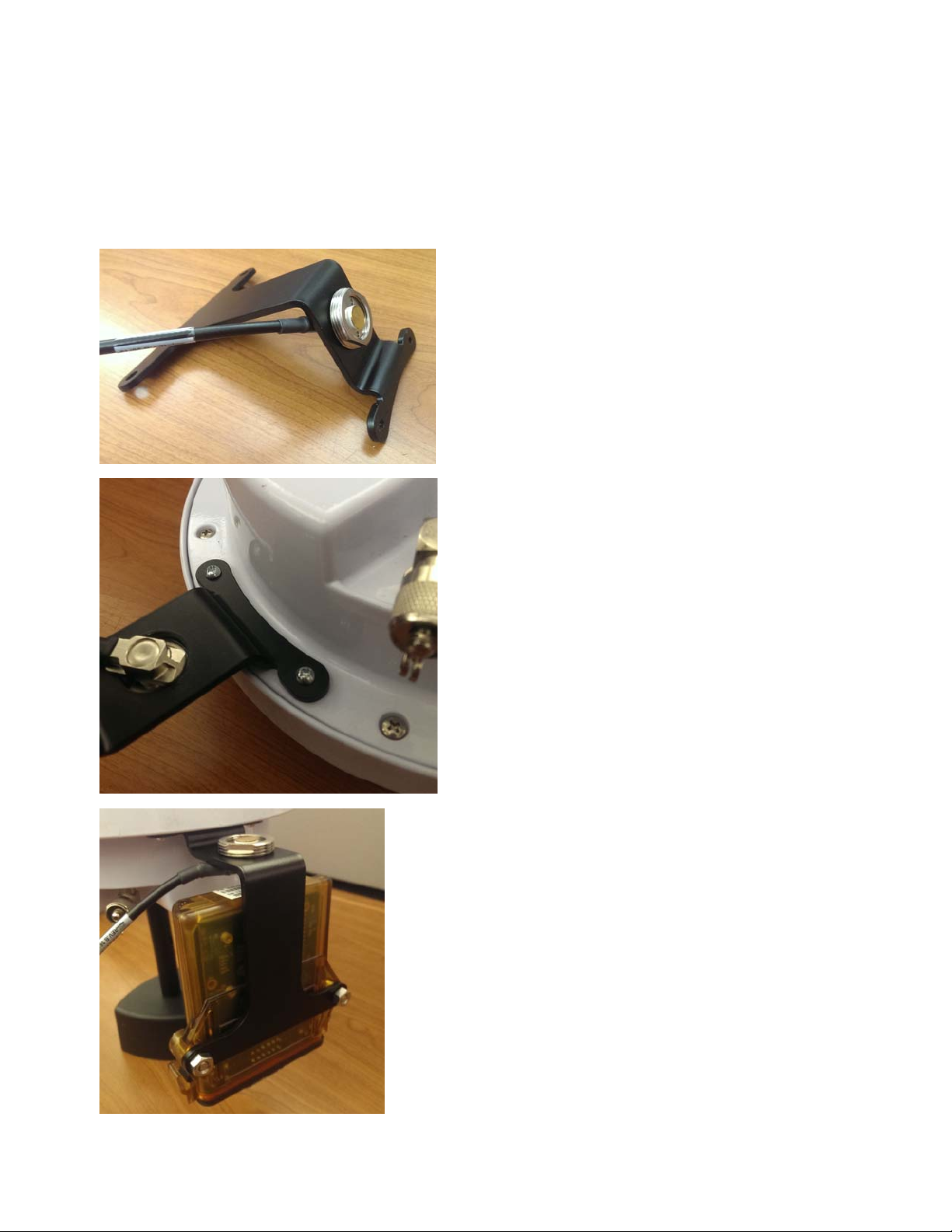
1. Install NMO mount in the radio bracket. Verify the side
with the o-ring is against the bracket and tighten with a
15/16” wrench.
2. Install the radio mount onto the GPS 2500B with the
included PHILLIPS ROUND HEAD SCREW, ZP 6-32
X.50IN.
GPS2500B
RTK RADIO INSTALLATION INSTRUCTIONS
3. Attach the RTK Radio to the bracket as shown using the
included PHILLIPS PAN HD., M6-1.0 X 25 and HEX NYLOCK
NUT - ZP, 6MM.
4. Attach the coax cable to the RTK Radio.
1 PN 2006358 Rev. B
Page 2
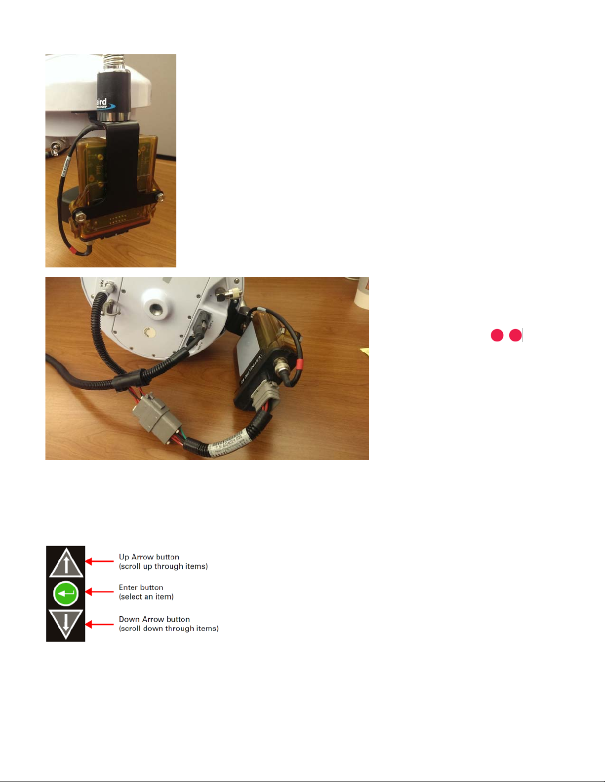
5. Install the RTK antenna onto the NMO mount.
6. Install cable 4004021-8 as
shown.
-a.Insert the round connector into the
PWR port on the bottom of the GPS
2500B. Align the red dots .
-b.Insert the 9-pin serial connector
into Port A on the bottom of the GPS
2500B.
-c.Insert the 12-pin Deutsch connector
into the RTK Radio
adapter/programming cable
(p/n 4004024-006).
7. Apply power to the GPS 2500B and verify the internal light on the RTK Radio powers.
-a. Once RTK corrections are being sent to the radio, the Green LED will flash Yellow about once per
second.
Configure the GPS 2500B to send corrections to the external radio using the LCD panel and the buttons
shown below:
8. Configure the Data Output Format:
-a. GPS > Configure > Data PORT A
-b. Select CMR+ or RTCMv3 (if using GLONASS)
2 Installation Instructions
Page 3

9. Configure the Baud Rate:
-a. System Setup > Baud Rates > Data PORT A
-b. Select 38400
10. Programming the radio channel/frequency
-a. AFLink Lite is available from www.agleader.com
-b. Requires External Radio Programming Cable Kit (p/n: 4002136)
Default Channel/Frequency:
900 MHz – 667
4xx MHz – 462.1250 (12.5 kHz spacing)
Note: See the GPS 2500B user manual for additional information
GPS2500B
RTK RADIO INSTALLATION INSTRUCTIONS
3 PN 2006358 Rev. B
Page 4

4 Installation Instructions
 Loading...