

Page 1

GPS 2000/2100
Operator’s Manual
Copyright 1998 Ag Leader Technology
Page 2

Page 3

GPS 2000/2100
Table of Contents
The following sections appear in this manual:
1-1
2-1
Initial Setup
2-1
Harvest
2-3
Mobile Applications
2-4
Soil Sampling
2-5
Site Verification
2-8
3-1
General
3-1
Keypad Functions
3-3
Standard Mode
3-4
Mark Key
3-5
Screen Description
3-5
On-Screen Map
3-6
Selecting a Map Scale
3-7
Calculating Area
3-9
Tape Measure Feature
3-9
Internal Memory Size
3-11
Logging Data
3-12
Making Spot Marks
3-13
Nav
Key 3-13
Navigating to a Point or a Mark
3-14
Run Key
3-15
Setup Key
3-15
Program
3-15
Send Mem
3-15
Load Mem
3-16
TSIP 3-16
Log Ext. 1 and 2
3-16
Edit Mark
3-16
Edit FLD
3-17
Edit Log
3-18
Ag Leader Technology
Table of Contents
General
Setup
Operation
Section Page
April 1998
Page 4

Table of Contents
GPS 2000/2100
Setup cont.
Edit Format
3-18
NMEA Message
3-20
Sat Opt
3-21
Beac Opt
3-22
Rad Opt
3-23
Elv\Spd 3-24
Freq\Loc 3-25
Set Units
3-25
Version #
3-26
4-1
Installing the Utilities Program
4-1
Changing Data Type Names
4-2
Changing Field Names
4-3
Changing Mark Names
4-4
Saving or Loading a set of Names
4-4
Transferring Logged Data to a PC
4-5
Converting Internal Format to AL2000 or HEXASCII Formats
4-7
Creating New Data Files
4-7
Editing Data from the GPS 2000
\
2100 4-8
Separa
ting Fields
4-9
Updating the GPS 2000
\
2100 Programming
4-9
5-1
6-1
7-1
8-1
9-1
* * *
Operation cont.
Section Page
Ag Leader Technology
Software
Troubleshooting
Parts List
Installation
Reference
Index
April 1998
Page 5

GPS 2000/2100
General Overview
1-1
Welcome to the
Ag Leader Technology
family.
Ag Leader Tech
nology
is
We want to he
ar from you! Feel free to call any time to discuss:
We will do our best to ensure that you are happy with your current system
Ag Leader Technology
will periodically mail you a software upgrade that
Ag Leade
r Technology
will repair or replace, at no charge, any component
Warranty is not provided for damage
resulting from abuse, neglect,
Ag Leader Technology
Welcome
System Upgrades
Limited Warranty
dedicated to developing advanced, yet practical and cost-effective tools for
grain production. Above all, however, we are dedicated to meeting your
needs for support of existing products and development of product
improvements.
• Operational problems with your system
• Features you don’t like about your system
• Features you would like added to your system
and that it is upgraded in the future to better meet your needs.
replaces the existing program in your GPS 2000/2100 unit. The new
software will upgrade your unit with new features and improvements on the
current features.
To receive upgrade software and new product news, you must send in or
fax (515-232-3595) the Registration Form that is at the beginning of the
operator’s manual. Our mailing address is:
You can also reach us at our web site: http://www.agleader.com
of the GPS 2000/2100 system that fails during normal service for which the
system is intended to be used within two years from the date of first use.
accidents, vandalism, acts of nature, or any other causes that are outside the
normal, intended use of the GPS 2000/2100 system.
Ag Leader Technology
2202 South Riverside Drive
Ames, IA 50010
April 1998
Page 6

General Overview
GPS 2000/2100
1-2
Ag Leader Technology
shall not be liable for indirect, incidental, or
If you have a problem with your system call us directly at the phone number
Note:
Return failed hardware to us by UPS (preferred) or US mail.
Service
Copyright Notice
Ag Leader Technology
consequential damages to the dealer, end user, or third parties arising from
the sale, installation, or use of the GPS 2000/2100 system.
below. If we determine you have a hardware failure, we will ship
replacement hardware immediately. Our mailing address and phone
numbers are:
Ag Leader Technology
2202 South Riverside Drive
Ames, IA 50010
Phone: 515-232-5363
Fax: 515-232-3595
Ag Leader Technology has copyrighted (1998) the contents of this
manual and the operating program for the GPS 2000/2100 system. No
reproductions of this material may be made without first obtaining the
consent of Ag Leader Technology.
April 1998
Page 7

GPS 2
000/2100
Introduction
1-3
GPS is the acronym for
G
lobal
P
ositioning
S
ystem. The GPS system
DGPS
is the acronym for
D
ifferential
GPS
. This is a correction system that
•
•
Ag Leader Technology
What is GPS?
consists of 24 orbital satellites that are used to determine positioning on
earth. GPS receiver units, such as the GPS 2000/2100, use these satellites to
provide position data as you harvest, thus helping to map your movements
in the field.
What is DGPS?
allows your position to be calculated more accurately than with only GPS
signals. DGPS signals can originate from varying sources.
One form of correction originates from Medium Frequency (MF)
radiobeacons. These beacons are located worldwide, free, and are run by the
Army Corps of Engineers and the Coast Guard in the United States. The
GPS 2000 uses the free MF radiobeacon system for its DGPS.
Another form of correction can be obtained from satellites. This correction
type requires a yearly subscription from a satellite correction provider. This
method can provide a higher degree of accuracy in some coverage areas and
allows for usage in areas not currently serviced by the MF radiobeacons.
The GPS 2100 has the ability to use either of these methods of differential
correction.
GPS 2000 Features
GPS 2100 Features
The GPS 2000 unit contains a combined twelve-channel GPS and
radiobeacon receiver board. It uses DSP, Digital Signal Processing, for
the radiobeacon signals, and it tracks two beacons at all times. Trimble
Navigation, the leading company making GPS receivers, manufactures
the receiver board.
• The system has a Trimble combined GPS/DGPS antenna.
• The unit features a graphics display and keypad.
• The unit is programmable, which means it can be updated in the future
to meet the user’s needs.
The GPS 2100 has all the features listed above for the GPS 2000.
• Has the ability to also use satellite based differential correction.
• Choice between using either Omnistar or Racal to provide the
differential correction service.
April 1998
Page 8

Introduction
GPS 2000/2100
1-4
The primary difference between these units an
d others on the market is
* * *
GPS 2000/2100
Advantages over
Other Systems
Ag Leader Technology
The GPS 2000/2100 systems are submeter class receivers, which means
they can be extremely accurate under certain conditions as compared with
lower-accuracy and cost systems. This accuracy allows the GPS 2000/2100
to provide accurate speed to the Yield Monitor 2000, thus eliminating the
need for a radar gun and eliminating slip problems associated with wheel
sensors.
The units can also store data in their 128K memory, which allows the user
to take the units out in the field by themselves to mark points and
boundaries. This is tied in with the ability to navigate back to marked points
in the field, and to navigate to soil sampling sites.
The GPS 2100 adds the ability to use two different forms of differential
correction in one unit. The user can choose to use either the free MF
radiobeacons for corrections or subscribe to Omnistar or Racal satellite
services to provide differential. This allows for total flexibility should
problems arise with one source of differential or a MF radiobeacon is added
in your area.
versatility and the ability to upgrade. Instead of being a single operation and
use device the GPS 2000/2100 allow the user to put more precision into
farming.
April 1998
Page 9
GPS 2000/2100
Setup
2-1
The GPS 2000/2100 syst
em can be used for various functions. This section
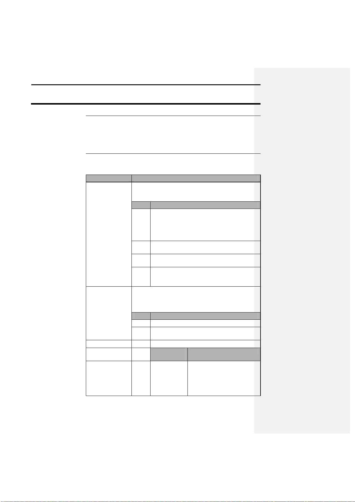
The following provides information on GPS 2000/2100 factory settings:
Beacon selection
The GPS 2000/2100 is set in Auto range mode. This
1
Set the unit in standard mode.
2
Press the SETUP key until BEAC OPT is
3
Press F3 again to place the unit in Manual
4
Set the desired beacon frequency.
Satellite selection
This option is available on the GPS 2100 only. If you
1
Set the unit in standard mode.
2
Press the SETUP key until SAT OPT is above
3
Press F1 to select Satellite differential.
4
OMNISTAR
covers your usage area best.
Ag Leader Technology
Overview
Initial Setup
covers a few possible applications, but it is not comprehensive because the
user may discover applications that Ag Leader Technology has not
attempted or tested.
Operation Setting
normally is acceptable, but if the user prefers to set the
receiver to a particular beacon, do the following:
Step Action
Note: Standard mode refers to the screen that
the GPS 2000/2100 starts up in after the power
has been turned on. This is the default screen.
above F3. Press F3.
mode.
Refer to section 3, Operation, for more
information about making this change.
will be using the satellite differential option then do the
following depending on which service provider you
select:
Step Action
the F2 key. Press F2.
If you will be
using….
Then …
Press the F2 key to select
Service
the SAT SOURCE: that
Apri1998
Call the OMNISTAR
subscription number
Page 10
Operation
GPS 2000/2100
2-2
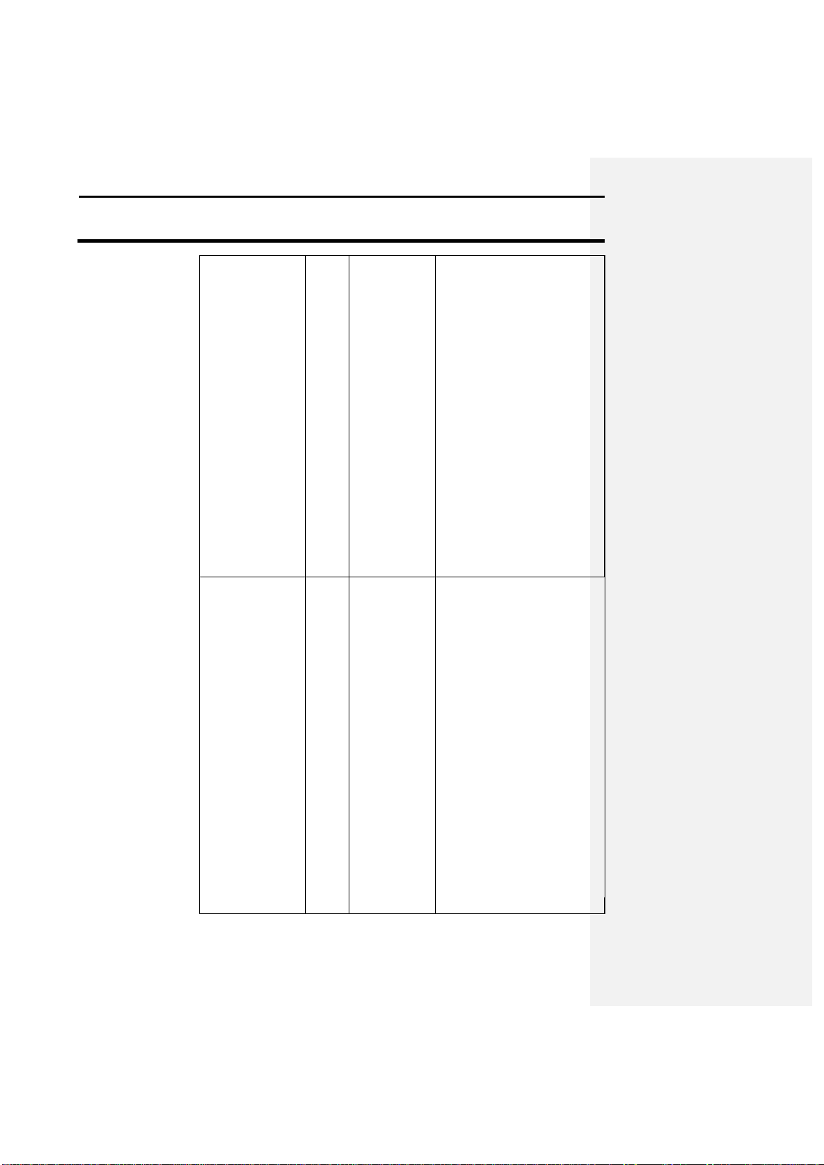
RACAL
Ag Leader Technology
provided and give them the
number to the right of GPS
SERIAL#. OMNISTAR
will then give the user a 24digit code for the serial
number that was given.
Key the code in to the right
of OMNISTAR CODE:
using the arrow keys. Once
the code is entered press the
F3 key to send the code to
the GPS board inside the
unit. Now press the F4 key
to quit this screen and
return to standard mode.
Let the receiver run for at
least 30 minutes, after
which the receiver should
start receiving corrections
and display “DIFF ON”
Service
Press the F2 key to select
the SAT SOURCE: that
covers the usage area best.
Call the RACAL
subscription number
provided and give them the
number that is displayed to
the right of GPS SERIAL#.
RACAL will then activate a
code for the serial number
that was given. After the
serial number has been
called in, press the ENTER
key to return to standard
mode and wait for DIFF: to
change from OFF to ON.
Within 15-30 minutes the
receiver should start
receiving corrections from
RACAL.
April 1998
Page 11

GPS 2000/2100
Setup
2-3
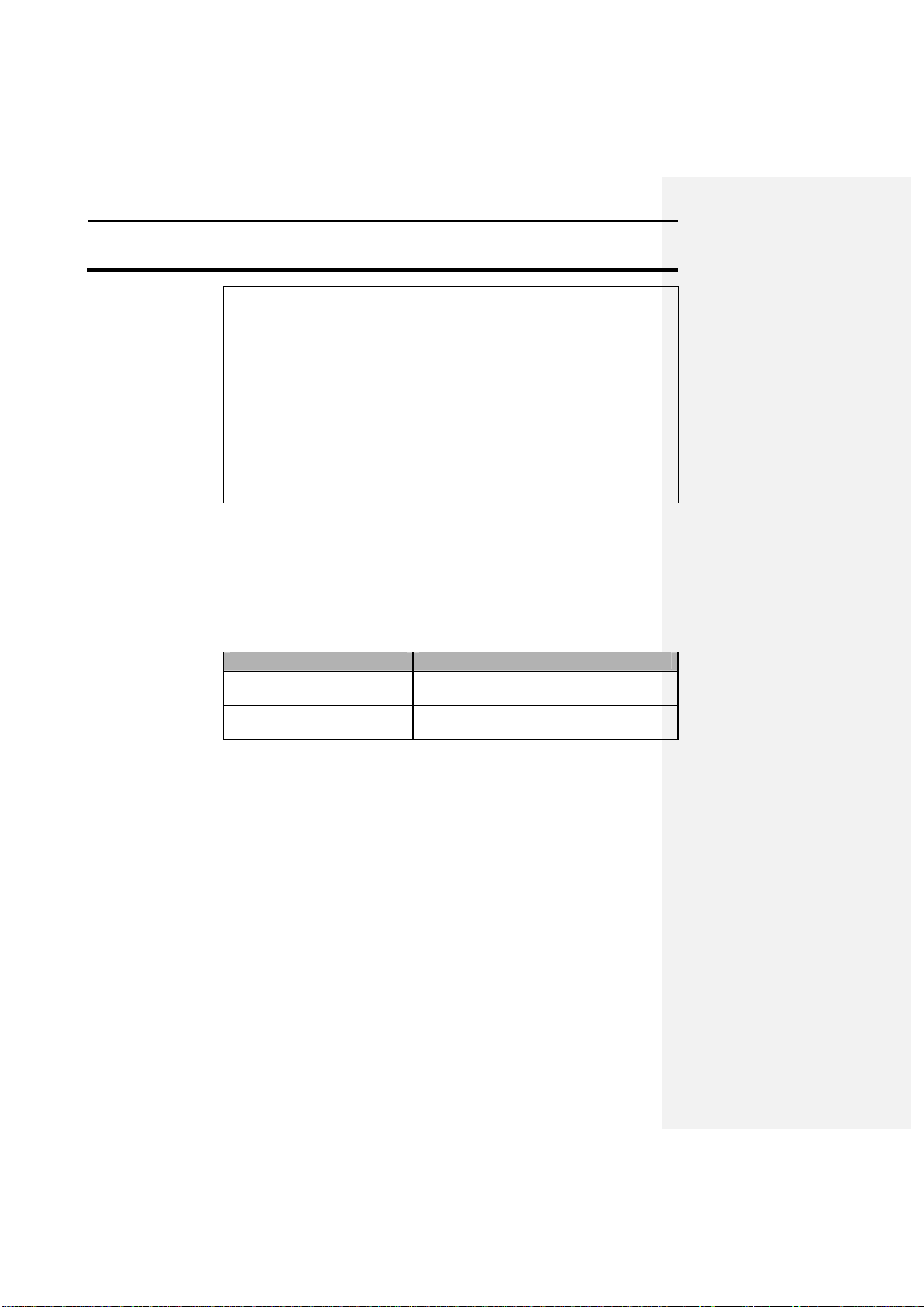
NMEA message
The GPS 2000/2100 has only the GGA NMEA string
Changing field,
The user can either change these names on the receiver
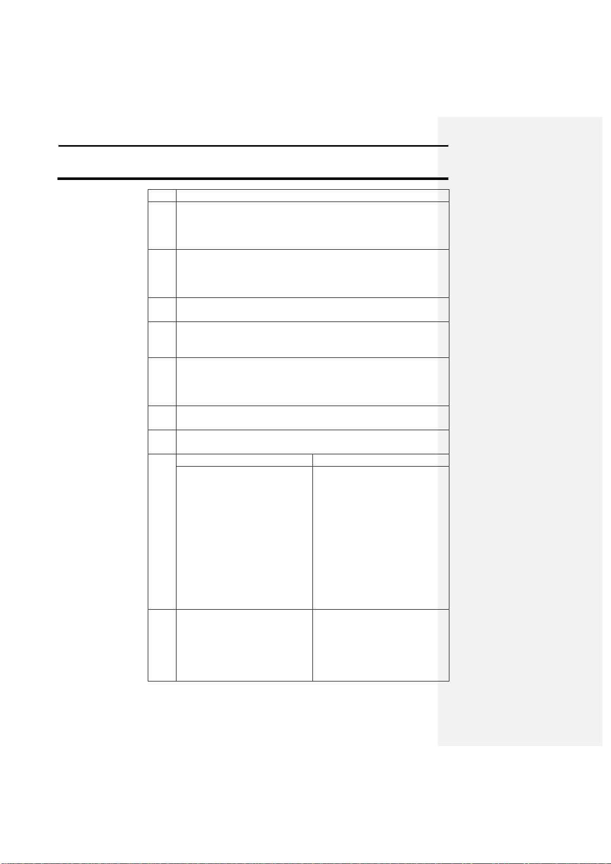
Follow these steps to set up the rec
eiver for harvest operation:
1 Attach the 10
-
foot coaxial cable inside the cab to the cable
2 Turn on the receiver.
3 Verify whether the yield moni
tor is receiving data from the
Ag Leader Technology
Harvest
selection
data type, and
mark names
Step Action
connection on the receiver.
Important: Make sure the y-cable connecting the yield monitor
and the receiver is securely connected, and the two connectors
attached to the receiver are connected to the indicated ports.
Result: After a few seconds various types of information should
appear on the screen. After the unit becomes oriented, it will
indicate a number of satellites and whether it is receiving a
differential signal.
Note: The screen may take a few minutes to display data because
the unit must adjust to its location and acquire a good lock on
satellites and a differential source.
receiver:
a) Turn the yield monitor on.
b) Under the yield monitor SETUP key, make sure that a memory
card has been detected. See the Yield Monitor 2000 manual for
more information on setting up the yield monitor to log GPS
turned on initially. It is the only message string that the
Yield Monitor 2000 needs for position data. If the user
wants to use the GPS 2000/2100 to provide speed to
the Yield Monitor 2000 or display speed on the GPS
2000/2100 itself, then the VTG message must also be
turned on. Depending on the proposed use of the GPS
2000/2100, other messages may need to be turned on.
See section 3-21 for more information on changing the
NMEA strings that are output.
or use the GPS 2000/2100 Utilities program provided
with the system to enter the desired names.
Refer to sections 3 and 4, Operation and Software, for a
description of this process.
Apri1998
Page 12
Operation
GPS 2000/2100
2-4
data.
The GPS 2000/2100 system was de
signed to provide a great deal of
In a vehicle that has a
The GPS cigarette power cable.
On an all
-
terrain vehicle
The GPS ATV/tractor power cable.
Mount the GPS 2000/2100
-
display
unit in a location that is secure and clear
Mobile
Applications
Ag Leader Technology
c) Select the desired logging interval.
d) Go to the field and load into which you will be putting data.
Result: An upper-case D and G should be in the top right
corner of the screen on the yield monitor, which indicates that
you have GPS and differential signal from the receiver. You are
now ready to harvest.
Note: The marking functions can be used while harvesting, but
keep in mind that any marks made with the GPS 2000/2100 while
harvesting are not stored on the memory card. They are stored only
in the GPS 2000/2100’s memory and will not show up on the yield
map, but on a separate map downloaded from the GPS.
versatility for alternative applications. The only limitations to usage are
availability of power and a secure mount for the antenna.
The appropriate power cable for the GPS 2000/2100 depends on the type of
vehicle you are using:
If you are . . . Then use . . .
cigarette lighter,
(ATV) or tractor,
of interference from moving parts. The provided U-bracket may suit this
requirement best.
The antenna can be mounted on any metal surface, as long as the dome side
of the antenna is pointing up towards the sky. To avoid noise problems from
vehicle electrical systems, you may need to move the antenna around the
vehicle until you find a suitable location. Finding a suitable location may
require building a small stand for the antenna so that it can be placed an
acceptable distance from interference.
After the system is securely mounted and all the wires are connected, turn
the GPS 2000/2100 on.
Note: The unit may take a few minutes to orient itself and provide a lock
on satellites and a differential source, then it is ready to run.
April 1998
Page 13

GPS 2000/2100
Setup
2-5
Ag Leader Technology
Soil Sampling
Using the GPS 2000/2100 the user has the capability to enter sample
locations, navigate to these points, and then mark the site where the
sample was taken. To transfer data to and from the GPS 2000/2100
the user will need to install the GPS 2000 Utilities program provided
with the system. Refer to section 4, Software, to install the GPS
Utilities program and general usage instructions.
The following is a description of how to collect soil samples using the
GPS 2000/2100:
Step Action
1 Use a software program capable of griding fields to generate a
soil sample grid map.
2 Write down the LATITUDE & LONGITUDE for each point or
print out a copy of the locations. Also record the total number
of samples that will be collected in the field.
3 The user must now create a new file with the desired sample
points in it. Follow the steps starting on 4-8 to create and save
this file. The file created must be saved in the HEXASCII
format before it can be transferred into the GPS 2000/2100.
4 From the main window of the GPS Utilities program, click on
the MEMORY button. Click on the TRANSFER TO GPS
button. Select the file that was modified with the sample points
and click OK. Follow the on screen instructions and place the
GPS unit in LOAD MEM mode. The progress indicator in the
lower right-hand corner of the screen will indicate that data is
being transferred to the GPS unit.
5 The program will now prompt the user to put the GPS unit
back into LOAD MEM mode to complete the transfer. Once
the unit is in the correct mode click OK. When completed the
GPS unit will return to standard mode.
6 On the GPS 2000/2100, press the MARK key. Using the arrow
keys select a field that contains sample data. The screen should
indicate the number of points that you entered. Press the
SETUP key once and then press the F2 key to select the
RESCALE function. A map of the points that were entered for
the field should now be visible on the screen. Press SETUP
again and press F4 to QUIT and return back to mark mode. The
Apri1998
Page 14
Operation
GPS 2000/2100
2-6
Ag Leader Technology
map should still be visible.
7 Return to standard mode by pressing the RUN key and then
press the NAV key. Once again select a field that sample data
was entered for. The latitude and longitude that were entered
for the first sample site should now be shown on the screen.
8 The GPS 2000/2100 now has the locations of the sample sites
loaded into memory and is now ready to guide the user to the
indicated sample sites and record the location that the samples
are taken at.
9 Refer to the instructions on Mobile Applications, section 2-4,
to setup the GPS 2000/2100 for usage on a vehicle.
10 Once the user has the unit mounted and is ready to head for the
first sample point put the unit in navigation mode by pressing
the NAV button.
11 Select the field that contains the sample sites and the distance
in two directions should be displayed. These distances refer to
the direction and distance that the user must travel to reach the
indicated location.
12 Once the point is reached, stop the vehicle and press the RUN
key to get back to standard mode.
13 The user has several options for recording the current location
of the samples:
Names each MARK (up to 32)
as a different sample point.
If the user… Then
From the standard mode, use
the UP and DOWN arrow
keys to scroll through the
marks until the user sees the
desired spot mark. Press the F
key below the mark name to
log that point. The GPS unit
will now go into mark mode
and make one mark. Press the
RUN key to return to standard
mode then the Nav key to
continue to the next point.
Names each FIELD, (up to
255), as a different sample
point.
From standard mode, press the
MARK key and then select
the field for logging. Turn
logging on and off manually
by moving the cursor to LOG
and then use the UP or
April 1998
Page 15

GPS 2000/2100
Setup
2-7
Ag Leader Technology
DOWN arrows to turn logging
ON and OFF. Or use a mark
above the F keys to log one
point to the field. Press the
Run key and then the Nav key
to continue to the next point.
Now change to the next field
to represent the next sample
point.
14 Repeat steps 11-13 for each point until all the samples have
been collected.
The following steps describe an alternate method for taking soil
samples using the GPS 2000/2100:
Step Action
1 Use a software program capable of generating grid maps to
create soil sample sites.
2 Write each sample location down or print off a copy of the
latitude and longitudes.
3 Turn the GPS 2000/2100 on and place it in standard mode.
Press the MARK key.
4 Select a field that will not be used to log any other points in
when the sample locations are recorded. Press one of the F
keys to make a mark. Return the GPS to standard mode by
pressing the RUN key.
NOTE: The GPS unit must have data in it to be able to
manually put coordinates in for navigation, thus the need for
this step.
5 Go to the field where the samples will be collected. From the
standard mode of the GPS 2000/2100, press the NAV key.
6 Press the F1 key. A cursor should now be flashing on the first
number of the LAT: value.
7 Use the arrow keys to move the cursor to the right and adjusts
the values. As the user changes the values and the desired
number is entered, the directional headings and distance to the
point should update and indicate which direction and distance
the user must travel to reach the sample site entered.
8 Once the user reaches a sample site follow steps 12-14 of the
previous instructions.
Apri1998
Page 16

Operation
GPS 2000/2100
2-8
For site verification, the unit most likely will be mounted on a tractor. If this
The following steps represent the recommended method to operate the unit
1 Place the GPS 2000/2100 in MARK mode by pressing the MARK
2 Use the directional
arrow keys to select the field that data will be
3 The user must now decide how they will differentiate the data that
4 Now select a logging interval (INT
:)
which is located on the MARK
5 After all the names have been entered and the field that data will be
Ag Leader Technology
9 After the site is marked return to navigation mode and enter the
next site to navigate to. Navigation mode will continue to only
allow the user to enter in manual location values until the user
presses the enter key.
10 Repeat steps 7-9 until all the sample sites have been logged.
Site Verification
is the case, the GPS 2000/2100 can be powered with the supplied GPS
ATV/tractor power cable or the GPS cigarette lighter cable.
for site verification:
Step Action
key.
logged in. If a field name has not been entered the user has the
option to manually key the name in by going to EDIT FLD which
can be found from the standard mode using the setup key. Or the
user can use the GPS Utilities program to enter in custom names
(refer to 4-3). If the user wants to change the data type to be used
they must create or edit the name using the Utilities program and
then select that data type for the desired field using the EDIT FLD
option.
will be collected in the field. It is recommended to use the available
32 marks to distinguish differences in a field. An example would be
to name the marks on the basis of the different hybrids that will be
planted.
screen. Use the directional arrow keys to select a logging interval
that will provide enough memory to complete a desired amount of
work. NOTE: If you use a logging interval greater than 3 you will
need edit it back to 1, 2 or 3 sec. using Excel
logged in is selected, the user has two options for logging.
• Set LOG: to ON by moving the cursor to LOG and use the up,
down arrow keys to turn logging on and off. Then activate
either spot or continuous marks as needed.
Or
• Activate a continuous mark and also use spot marks.
April 1998
Page 17

GPS 2000/2100
Setup
2-9
For more information on editing names and logging data se
e sections 3 and
Another possible configuration is to use the Yield Monitor 2000 to collect
* * *
Ag Leader Technology
Note: To activate a continuous mark press the MARK key followed
by the appropriate mark.
To activate a spot mark, press the appropriate F key
Either method is valid but the first option will provide maps with
greater detail and less gaps.
Collecting Site
Verification Data on
a Memory Card
4, Operation and Software.
the site verification data on a memory card, which allows the user to name
fields and loads like the Yield Monitor does during harvest. Follow the
setup steps above under Collecting Data, but note that the GPS 2000/2100 is
not used to log the data. Refer to the Yield Monitor 2000 manual for more
instructions on this procedure.
Apri1998
Page 18

Page 19

GPS 2000/2100
Operation
3-1
This section of the manual will be updated as new features are added to the
The GPS 2000/2100 system utilizes the latest technology for use in
The display is a graphics display, which means that it can display images
Ag Leader Technology
Important Notice
unit, and current features are revised. When you receive your software
updates, you also will receive new sections or pages for your manual that
will explain the new features and updates.
General Description
agriculture for GPS and DGPS. The front cover of the receiver has a 13button keypad, a power switch, and a graphics display. The unit also has
three 9-pin ports that provide power, GPS message information, secondary
differential source access, and allow for the transfer of data to and from the
GPS 2000/2100.
Display and Keypad
and characters. The keypad has 13 buttons, most of which are flexible in
function for future upgrades.
Apri1998
Page 20
Operation
GPS 2000/2100
3-2
The unit is turned on and off with the rocker switch in the upper right corner
The unit has three 9
-
pin serial ports.
The antenna is a combined antenna, hous
ing the GPS and DGPS antennas.
A magnetic base attached to the bottom of the antenna housing provides
Power Switch
Serial Ports
Antenna
Ag Leader Technology
of the keypad (POWER).
Note: Always turn the GPS 2000/2100 unit off when you leave it in the cab
because the unit draws power from the Yield Monitor 2000, even when the
yield monitor is off. If the GPS 2000/2100 is left on, the unit could run
down the vehicle battery.
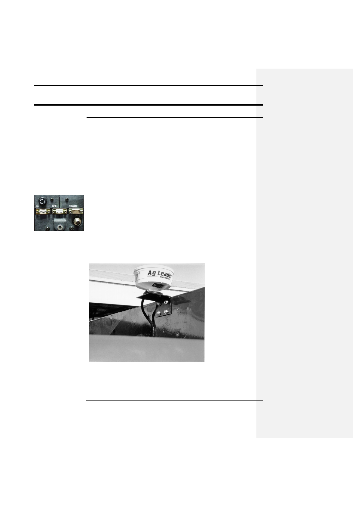
• The right port, labeled POWER, provides power to the unit and access
to a secondary differential system.
• The middle port, labeled GPS, sends NMEA messages to the Yield
Monitor 2000 or to an external data logger.
• The left port, labeled PC, provides access to the unit for updating,
troubleshooting, and data logging.
easy mounting on metal surfaces. The magnetic base also breaks away if
any object strikes the antenna. The antenna is mounted to a combine with
the provided L-bracket (shown in the photo above).
April 1998
Page 21

GPS 2000/2100
Operation
3-3
The MARK
key activates the marking mode and screen. In this mode, the
The NAV key activates the navigation mode and screen.
In this
mode, the
The RUN key
is used to ret
urn the user to standard mode, unless otherwise
Pressing SETUP
allows
you to scroll through various operating and
You use F1, F2, F3, and F4
to select the current option or selection that is
The directional keys
allow the user to change or edit values and activate
Ag Leader Technology
Keypad Functions
The following information pertains to the functions of the keys on the GPS
2000/2100 keypad.
user can log data internally in the GPS 2000/2100 and mark locations on the
basis of a field name/number and a data type.
user has the option of selecting a location based on each individual point
logged, or the user can scroll through the marks made in that field and then
navigate back to the point.
specified by other “on screen” instructions.
configuration options in standard and Mark modes. The setup options are
displayed above the F keys. It also has specialized functions that, when
applicable, are explained on the screen.
displayed above these keys on the screen.
, ,
,
certain functions on the screen. Use the left and right keys to move the
cursor from one editable/changeable location to another. Use the up and
down keys to change a value or activate a function that the cursor is on. The
ENTER key is configured for multiple uses, and its current use is displayed
on the screen if it has a function.
Apri1998
Page 22

Operation
GPS 2000/2100
3-4
The standard mode is the mode in which the GPS 2000/2100 starts when
Screen Description
The following is a photo of the standard mode display. An explanation of
TIME
LAT Current latitude of the receiver in degrees
-
minutes.fractional
LON Current longitude of the receiver in degrees
-
ELV or
Current elevation of the receiver in feet or current speed
#SAT
Indicates the number of satellites that the unit is using. The
DIFF
Indicates ON or OFF, telling the
user whether a differential
SNR Signal
-to-
noise ratio indicates the strength of the correction
FREQ or
Indic
ates the frequency of the differential source that the GPS
STATUS
Indicates whether one of the external logging formats is
MARKXX
Four marks are displayed on the bottom of the sc
reen. The
Standard Mode
Ag Leader Technology
turned on. It provides basic position and receiver information.
the display and the information it provides follows.
Field Description
GPS timeGreenwich Mean Time, the current time in
Greenwich, England.
minutes.
minutes.fractional minutes.
SPD
displayed in MPH.
unit can track a maximum of twelve satellites.
signal is being used.
signal in relation to the amount of background noise that can
interfere with signal reception. A good SNR is 10-18.
LOC
2000/2100 is using or the location of the differential source.
turned on.
user can change the marks displayed by using the up and
down arrow keys. The user can select from 32 possible marks.
April 1998
Page 23
GPS 2000/2100
Operation
3-5
Pressing this key allows the user to log point and marker data to the internal
1 The user selects a field to log the data in and a data type to log it as.
2 The user can then select a logging interval, ranging from 1 to 20
3 Marks can also be logged, either with normal logging or just as
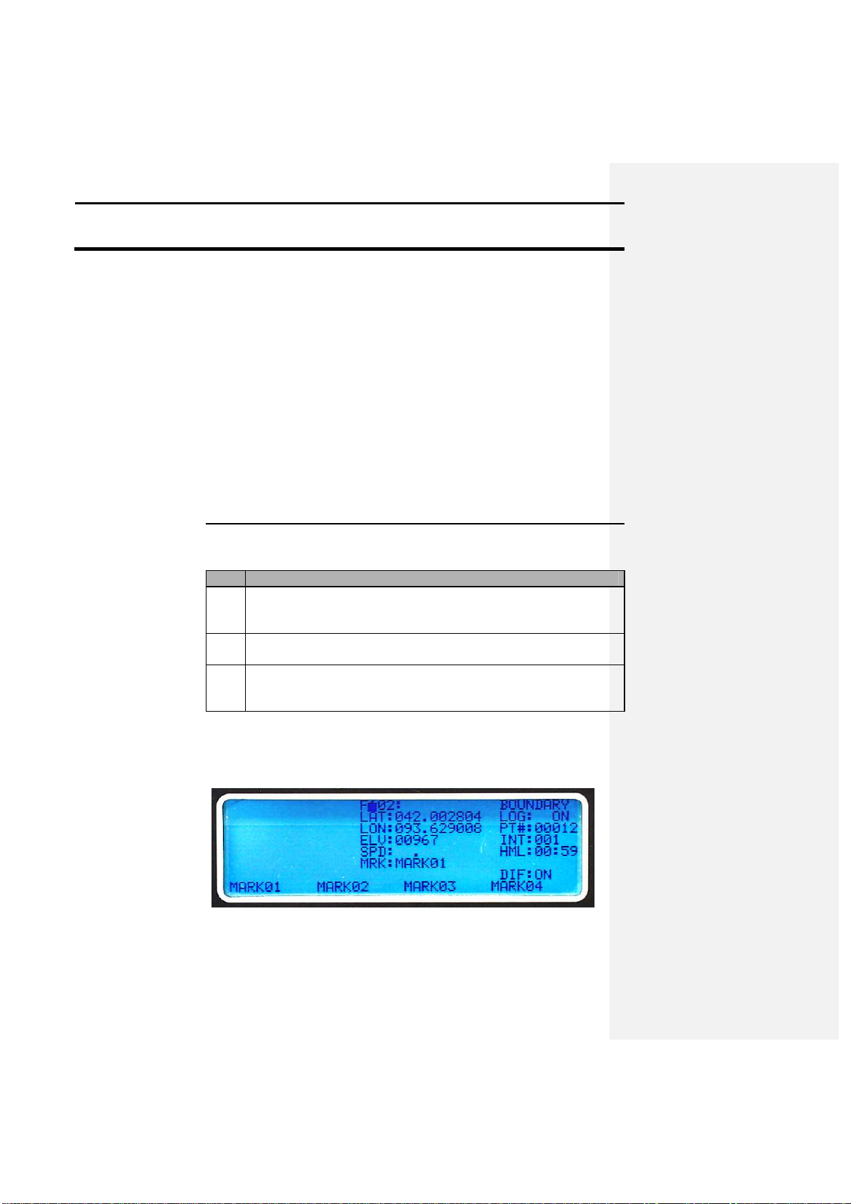
Screen Description
The following is a photo of the MARK screen. An explanation of the
Ag Leader Technology
General Information
The time displayed is the time at the Prime Meridian. This time is useful
mainly because the updating time indicates that the receiver is receiving
new information.
The format for latitude and longitude readings is ddmm.mmmm. This
reading will be different from that of the Yield Monitor 2000 because the
yield monitor displays the values in a different format, which is dd.dddddd.
(d=degrees, m=minutes). The PF3000 however, will use the same format as
the GPS 2000/2100.
To maintain differential correction, the unit must receive a minimum SNR
of 6.0 for radiobeacon differential. On average, the unit will run between 10
and 18 SNR, depending on your location in relation to a beacon. For
satellite differential an SNR of 4.0 must be received. An acceptable range is
6 – 10.
Mark Key
memory as follows:
Step Action
There are 256 possible fields and 20 data types, all of which can be
edited.
seconds.
individual or continuous marks. There are 32 possible mark
selections, which also can be edited.
display and the information it provides follows.
Apri1998
Page 24
Operation
GPS 2000/2100
3-6
F000:XX
The field number and name the user selects in which to log
Boundary
Data type that the data will log as. Can be edited using the
LAT:
Current latitude in ddmm.mmmm.
LON:
Current longitude in ddmm.mmmm.
ELV:
Current elevation in feet.
SPD: Current speed in mph.
MRK:
Displays the mark that is being marked continuously if a
LOG:
Displays whether logging is turned on or off.
PT#: Displays the number of points that have been collected in a
INT: Displays the selected logging interval.
HML:
Hours and minutes left. This indicates the amount of time left
Mark01
One of four current marks that the user can select by pressing
DIFF:
This tells you whether you are receiving a differential
This function allows the user to see the lines and boundaries that they have
1 From the standard mode press the Ma
rk key, this will put you
2 Select the field that has known data points logged into it.
3 Press the setup key.
4 Press F1 to turn the map on.
5 Press the setup key.
6 Press the area key to display the acres in the boundary.
Ag Leader Technology
Description
data. This can be edited using the EDIT FLD option.
EDIT FLD option.
continuous mark is selected.
field.
in the interval memory to log points on the current logging
interval.
the corresponding F key below the mark name.
On-Screen Map
correction signal. It will be either ON or OFF
created. It also allows a person to display the number of acres in a
boundary.
Step Action
into the Mark mode.
April 1998
Page 25
GPS 2000/2100
Operation
3-7
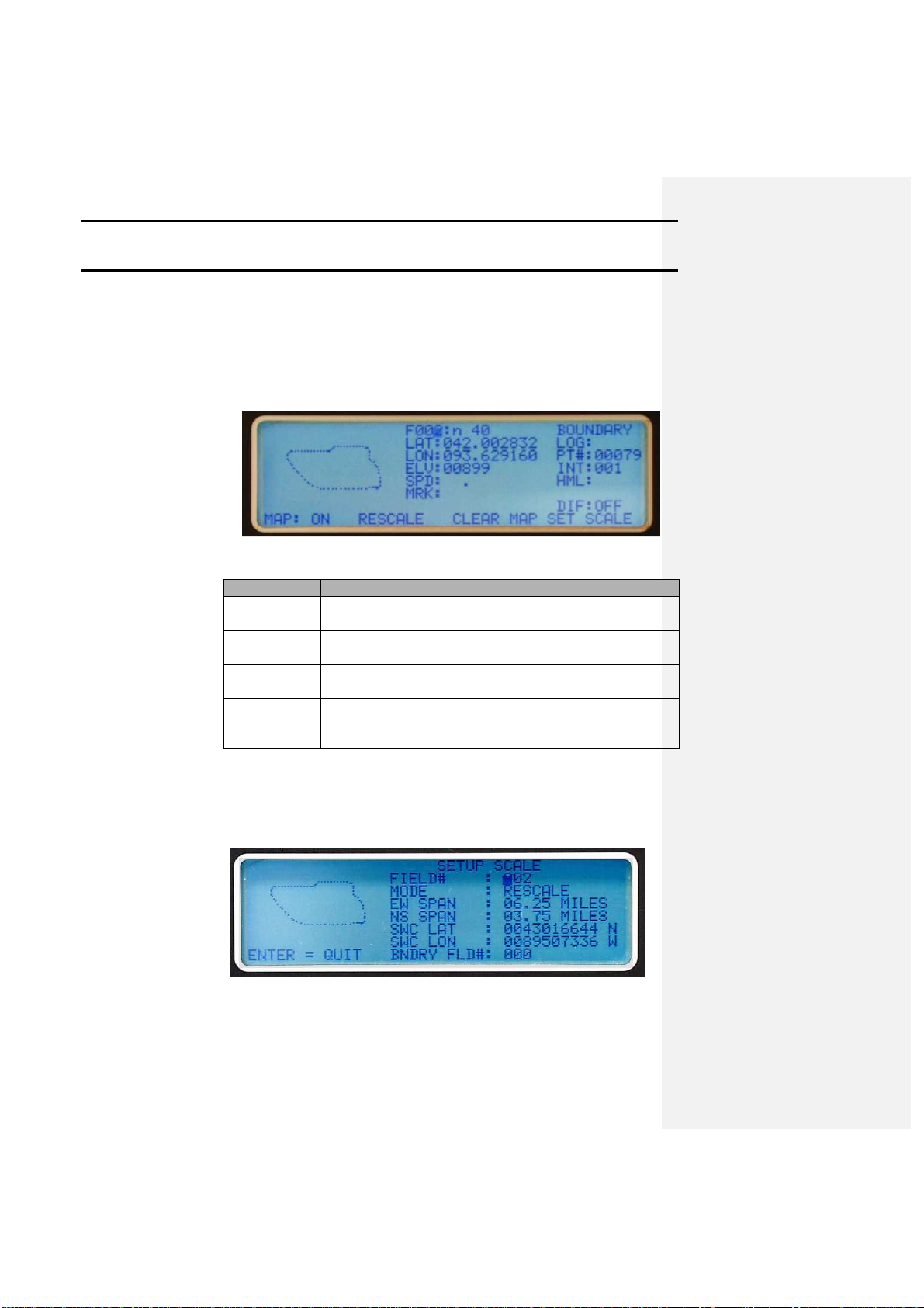
The following is a photo of the mark mode screen with the map option
MAP:ON
Displays the current status of the mapping option. The
RESCALE
Adjusts the scale of the map to provide a best
fit of the
CLEAR MAP
Erases the map that is being currently viewed from the
SET SCALE
Allows the user to select the type of scaling to be used for
Selecting a Map Scale
To create a point map on the GPS 2000/2100 the user must select an
Ag Leader Technology
On-Screen Map
activated. This is activated by pressing the setup key while in the mark
mode and then toggling the map on or off with the F1 key. The information
following the photo describes the setup options for generating the on screen
map.
Menu Option
Description
default setting is OFF.
logged data on the screen.
screen.
the map. The user has the following options: Span,
Rescale, Boundary, and Location.
appropriate scale so that the map generated on the screen will be viewable at
all times. To do this the user must select a scale using the available options.
The following photo is of the SETUP SCALE screen:
From the MODE line the user can select one of the following choices to
Apri1998
Page 26

Operation
GPS 2000/2100
3-8
scale the on
-
screen map:
The following describes how to set the scale for the on
-
screen map:
1
Set the unit in standard mode.
2
Put the unit in mark mode by pressing the MARK key.
3
Press th
e setup key.
4
Press the F4 key to select the SET SCALE option
5
Select the field that the scale is to be set for using the right arrow
6
Once a field has been selected use
the right arrow key to move the
RESCALE
The program will pick the best
SPAN
Move the curs
or using the right
BOUNDARY
Move the cursor down beside
Ag Leader Technology
• RESCALE: Automatically determines the best fit for currently logged
points to be displayed on the screen. This mode is best used after points
have been logged into the memory.
• SPAN: Allows the user to select an EW and NS span for the points to be
mapped. The maximum value is 26.56X15.93 and a minimum of
0.10X0.06 miles.
• BOUNDARY: Allows the user to select a field currently in memory to
be used as the scale. This is useful when returning to a field that has
already been boundary mapped using the GPS 2000/2100. This allows
for an optimum scale to be set for the area to be covered.
• LOCATION: This option allows the user to enter in a latitude and
longitude for the southwest corner of the area to be mapped. This helps
to provide a more accurate reference for the map and also allows for
better usage of the available screen area.
Step Action
key to move to the desired digit and the UP/DOWN keys to changes
the values.
cursor down beside MODE:. Use the UP/DOWN arrow key to
change the current mode selection.
If the user selects… Then…
fit for data that is already in
memory.
arrow key down beside EW
SPAN: and change the value
using the UP/DOWN arrow keys
to increment the value.
BNDRY FLD#: using the right
arrow key. Select the field
number that will be used for the
scale using the UP/DOWN arrow
April 1998
Page 27

GPS 2000/2100
Operation
3-9
keys.
LOCATION
Move the cursor down besides
6
Once the scale mode
has been set , press ENTER to return to the
Calculating area
If the user logs points in a manor that generates a perimeter map, such as a
The following describes how to display the area of an enclosed data set:
1
Set the unit standard mode.
2
Press the MARK key.
3
Select the field that contains data t
hat will be used to calculate the
4
After the field is selected or the data is recorded, press the SETUP
5
AREA: should now replace MRK: and the area in acres
will be
6
Press the F4 key to return to normal MARK mode.
Tape measure feature
Using this feature allows the user to drive from one point to another and
Ag Leader Technology
mapping menu screen and turn mapping on by pressing the F1 key.
boundary map (shown below), then the total area can be displayed for the
enclosed area.
SWC LAT: using the right arrow
key. Use the UP/DOWN arrow
keys to enter the desired latitude
and then repeat the process
above to enter in the longitude.
Step Action
area or collect the data now.
key until AREA is displayed above the F1 key. Press the F1 key.
displayed after a few moments.
display a straight-line distance as well as the path distance on the screen. A
map of the distance traveled is also displayed. The following photo
illustrates the tape measure feature and the text following the photo details
the screen options and values:
Apri1998
Page 28

Operation
GPS 2000/2100
3-10
START
Used to select the starting location for distance
HOLD
Freezes the screen display so that distances on the
CLEAR
Clears all current distance measure
ments.
QUIT
Exits back to the main screen in MARK mode.
PT-
PT DIST: and
These two values represent a straight
-
line distance
PATH DIST: and
These two values represent the actual path and
The f
ollowing describes how to use the Tape Measure feature:
1
Set the unit in standard mode.
2
Press the MARK key.
3
Press the SETUP key until MEASURE is displayed above the F2
4
The Tape Measure screen will now be
displayed, and on the left side
5
Now the screen will ask the user to SET START USING
-
>. Press
Ag Leader Technology
Screen options and
variables
measurements.
screen can be recorded without the value changing
or fluctuating.
TOT:
from the start point that was chosen to the current
location of the antenna. Every time the user presses
START without clearing the memory the PT-PT
DIST: is reset but the PT-PT TOT: will display the
sum of the segments that have been marked.
TOT:
distance that the user has traveled from the start
point. The map on the screen represents this travel
distance. When START is selected again the DIST:
value will rest to zero and the TOT: value will add
the last segment into its running total.
Step Action
Description
key. Press the F2 key.
of the screen a cursor will be flashing on the first digit of a number.
This value is the span for the map that will be displayed on the
screen. Use the arrow keys to change the value to the desired EW
span for the map. Once this is entered press the ENTER key.
April 1998
Page 29

GPS 2000/2100
Operation
3-11
the right arrow key to move an asterisk around the screen. Select a
6
The cursor will now flash to the right of # SAMPLES:, this
value
7
After the number of samples has been set press the F1 key to select
8
Once the user reaches the desired distance indicated next to PT
-
PT
9
If at any point the user wants to freeze the values on the screen to
10
To clear all displayed distances press the F3 key to select CLEAR.
The following table illustrates possible logging intervals and the resulting
Ag Leader Technology
point on the screen where the map will start and move the asterisk to
the nearest possible location. This is where the map will start, so
when choosing the start point consider the direction that will be
traveled from the start point.
Example: If the user will be starting at the north end of a fence line
that ends in the south east corner of a field, then the cursor should be
placed in the top left corner of the screen so that the map will stay on
the viewable area.
When the location has been selected press the ENTER key.
can be set from 1 to 250 samples, which represents the number of
samples that the unit will average together to provide a position for
measurement. If the user selects a value greater than one, the unit
must remain stationary while the unit is averaging. 1 sample
represents one second.
START. This will mark the users current location as the starting
point for measurement.
RESULT: As the user travels away from the start point, distances
will be displayed on the right hand side of the screen and a point
map will be generated on the left hand side.
DIST: the user can then press F1 to reset this value and use the
current location as the new start point or continue to drive and
display distance. If the user presses the F1 key the PATH DIST:
will also return to zero but the PT-PT and PATH TOT: values will
continue to add distance. These values are cumulative and each time
the user starts a new segment to measure the values from the last
segments are added into the total.
record values or mark a location select HOLD by pressing the F2
key to freeze the screen. Select START by pressing the F1 key to
resume keypad operation and screen updates.
Internal Memory Size The GPS 2000/2100 has 128K of memory available to store mark and
navigation data.
amounts of time that the GPS 2000/2100 can be used to log data before the
Apri1998
Page 30

Operation
GPS 2000/2100
3-12
memory is filled:
Logging
Time Left to Log
Logging
Time Left to Log
1
1:05 11 11:55
2
2:10 12 13:00
3
3:15 13 14:05
4
4:20 14 15:10
5
5:25 15 16:15
6
6:30 16 1
7:20
7
7:35 17 18:25
8
8:40 18 19:30
9
9:45 19 20:35
10
10:50
20
21:40
Logging Data
Follow these steps to log data:
1 Press the MARK key to access mark mode
. A cursor should flash on
2 Select the desired field number to log data in:
3 After selecting the desired field and data type, press the left or right
Ag Leader Technology
Interval
(Seconds)
(Hours and
Minutes)
(Seconds)
Step Action
the current field number.
a) Move the cursor to the digit in the field number that you want to
change by using the left or right arrow keys.
b) After you select a digit to increment, use the up or down arrow
keys to change the value of the current digit.
Result: A corresponding data type should appear with the selected
field.
Example: To select F152, move the cursor to the left-most digit
and press the up arrow key once to change the number from 0 to 1.
Repeat this process for each digit until the desired number shows on
the screen.
arrow key until the cursor flashes next to LOG:. To begin logging
data internally, press either the up or down arrow key. To turn
logging off, press the up or down arrow key again.
Note: The unit will make audible beeps each time it logs a point.
The points will show up on mapping software as dots color coded by
elevation.
Interval
(Hours and
Minutes)
April 1998
Page 31

GPS 2000/2100
Operation
3-13
1 Press the MARK key to access mark mode.
2 Select the desired field number/name
.
3 Use the left or right arrow key to position the cursor on the mark
4 Use the up or down arrow keys to scroll through the 32 possible
5
•
6 Another method of marking locations would be to select a mark
The following is a photo of the NAV screen. An explanation of the display
Ag Leader Technology
Making Spot Marks Follow these steps to make spot marks:
Step Action
name in the lower left corner of the screen.
mark names.
To make a mark with the desired name press the F key below the
corresponding mark name. Logging will begin for one logging
interval.
or
• Follow the previous four steps, but with logging already active.
from standard mode:
a) When the standard mode display appears with the default
information displayed the mark names are displayed above the F
keys.
b) Scroll through the 32 marks by pressing the up and down arrow
keys.
c) Press the F key below the desired mark name to make a mark.
The screen then switches to the mark screen and marks for one
interval.
d) To return to standard mode press RUN.
Note: Spot marks 1-4 will show on current software as attributes
such as a square, circle, triangle, or a X. Spot marks 5-32 will
show as a point or a dot.
NAV Key
and the information it provides follows.
Apri1998
Page 32

Operation
GPS 2000/2100
3-14
FLD: 152
Indicates the field number the user has sel
ected.
FNM: North 40
Shows the name entered for the selected field number.
PT#: 0002
Allows the user to increment through each individual
SMK:
Indicates that there is a spot mark in the data for the
CMK:
Same as SMK:, but it displays only marks made using
LAT:
Displays the latitude of the current point to which you
LON:
Displays the longitude of the current point to which you
Compass
Displays the distance in feet you must drive in a direction
1 Press the NAV key to access navigation
mode. The cursor should
2 Use the directional arrow keys to increment the field numbers to
3
Use the left or right arrow keys to move to either PT#: or
4 Use the up or down arrow keys to scroll to the desired point or
5 Another method of navigation is to manually enter in a Latitude
Ag Leader Technology
Field Description
point that was logged into the selected field.
LAT/LON displayed. The user also can scroll from mark
to mark in the selected field.
the continuous mark function.
will navigate in degrees-decimal degrees.
will navigate in degrees-decimal degrees
Directions
to reach the desired location.
Navigating to a Point
Follow these steps to navigate to a point or mark:
or Mark
Step Action
flash on the last digit of FLD: 000 or the last FLD selected.
the desired field.
SMK:/CMK:.
mark to which you want to navigate.
Result: A distance in feet should appear on two of the compass
directions, which indicates the distance you must travel in those
directions to reach the selected location. After you reach the
selected location, the numbers should read zero.
and Longitude value to navigate to:
a) From the navigation mode, press the F1 key. A flashing cursor
should now appear on the first digit of the LAT: value. Use the
UP/DOWN arrows to increment the values and the right arrow
key to move to the next value. After entering the LAT: value
enter the LON: value. As the user enters the manual location
the directional headings and distance to the location should
begin to update.
b) To exit the manual mode for navigation press the ENTER key.
April 1998
Page 33

GPS 2000/2100
Operation
3-15
Press the RUN key to return to the standard mode. This key also has
Press the SETUP key to access the GPS 2000/2100 options selections and
PROGRAM
Select this option to update the software in your receiver.
SEND MEM
Select this option, located under the s
etup key, to transfer data in the
Ag Leader Technology
Note: To use the manual navigation feature at least one point must
be logged in the field selected. This point does not have to be a
valid location or related to the manual value being entered.
RUN Key
specialized functions explained on the screen when they apply.
SETUP Key
different operation configurations from the standard mode. These options
are displayed above the F keys. This key also has specialized functions
explained on the screen when they apply.
Follow the instructions on the screen to connect the unit to a personal
computer. To update the GPS 2000/2100, use the GPS 2000/2100 Utilities
program and refer to section 4, Software.
internal memory to an external device through the PC port.
Apri1998
Page 34

Operation
GPS 2000/2100
3-16
Refer to section 4, Software, for an explanation of the use of this function.
LOAD MEM
Select this option, found under the setup key, to import data from an
TSIP Select this option under the setup key to troubleshoot the GPS board. The
LOG EXT 1
Select this option, located under the setup key, to send NMEA strings
LOG EXT 2
Select this option under the setup key to send a user
-
selected string of
EDIT MARK
Select this option under the setup key to activate the EDIT MARK NAMES
Ag Leader Technology
external source through the PC port, using either a communications
program or the GPS 2000/2100 Utilities program provided by Ag Leader
Technology.
Refer to section 4, Software, for an explanation of the use of this function.
provided software must be used to access this function.
Important: You should access this feature only if you are having problems
and have contacted Ag Leader Technology.
through the PC port. Data will still be logged internally in the GPS or sent
to the yield monitor.
ASCII text data through the PC port. THIS FUNCTION HAS BEEN
DISABELED
screen to change the names for each of the 32 possible marks. Use the left
or right arrow keys to select the values or characters you want to change,
April 1998
Page 35

GPS 2000/2100
Operation
3-17
then use the up or d
own arrow keys to change the values.
1
Set the GPS 2000/2100 in stan
dard mode.
2
Press the SETUP key until EDIT MARK is located above F1.
3
Use the directional arrow keys to select a mark number.
4
Use the left and right arrow keys to move the cursor down next
to
5
Press EN
TER to return to standard mode.
EDIT FLD
Select this option, found under the setup key, to activate the FIELD EDIT
Ag Leader Technology
Follow these steps to edit mark names:
Step
Action
Press F1, and the EDIT MARK NAMES screen should appear.
MARK NAME:. Now use the left and right arrow keys to move
from character to character in the name. The up and down arrow
keys are used change the current character that the cursor is located
on. The mark name can consist of 8 characters.
Another method of editing mark names is to use the GPS 2000/2100
Utilities program. To use this program to edit names see section 4,
Software.
SCREEN to edit field information. Use the directional arrow keys to select
the field number, then change its name and select a data type to correspond
with that field.
Follow these steps to edit field names and change data types:
Step Action
Apri1998
Page 36

Operation
GPS 2000/2100
3-18
1
Set the display to the standard mode
2
Press
the SETUP key until EDIT FLD is above F2.
3
Press F2.
4
Use the directional arrow keys to select a field #.
5
Use the LEFT/RIGHT arrow keys to move the cursor next to
6
Use the directional arrow keys to enter the desired name.
7 Using the directional arrow keys position the cursor by DATA
8
Press the UP/DOWN arrow keys to scroll through the available
9
Press ENTER when done.
Another method of editing field names and data types is to use the GPS
EDIT FORM
Select this option under the setup key to choose which data format to use
Ag Leader Technology
FIELD NAME:.
TYPE:.
data types.
Note: Data type names can not be edited on the GPS 2000/2100
screen, only selected from the 20 names in memory. To edit these
selections the GPS 2000/2100 Utilities program must be used, see
section 4, Software.
2000/2100 Utilities program. This process is explained in section 4,
Software.
EDIT LOG
Select this option under the setup key to edit the variables that are included
in the ASCII string that is sent through the PC port when the unit is set in
the LOG EXT 2 mode.
for exporting data. The two choices are
• The standard internal format that the GPS 2000/2100 uses. This format
includes all the specific data pertaining to a logged location. It is
necessary to download this format to convert the data to other formats
and for usage in future software packages.
• Advanced Ag Leader format. This format is the same that is used for
April 1998
Page 37

GPS 2000/2100
Operation
3-19
yield data, and thus lacks some of the information contained in the
Follow these steps to change the format of the data the GPS 2000/2100
1 Set the unit to the standard mode.
2 Press the SETUP key until EDIT FORM is located above F4. Press
3 To export in …
Then …
GPS 2000/2100 format
Press F4.
Advanced Ag Leader
Press the Up arrow key.
Follow these steps to clear internal memory:
1 Set the GPS 2000/2100 in standard mode.
2 Press the SETUP key until EDIT FOR
M is above F4, then press F4.
3 Press SETUP.
4 The GPS 2000/2100
5 Press the up arrow key to continue and eras
e memory. Press any
Ag Leader Technology
internal format. This format is useful to make maps in almost allmapping software that allows the user to import the Advanced Ag
Leader format.
This screen also allows you to clear the memory in the GPS 2000/2100.
outputs to a PC:
Step Action
F4.
Step Action
• Beeps long and audibly.
• Asks whether the user is sure he or she wants to clear the
memory.
• Gives instructions for proceeding on the screen.
other key to abort.
Note: Clearing the memory clears all points stored in the internal
memory and the field names. It does not clear data types or mark
names.
Apri1998
Page 38

Operation
GPS 2000/2100
3-20
NMEA MSG
Select this key, found under the setup key, to change the type and number
The following is a description of the NMEA messages that the GPS
NMEA
Message
Description
GGA
Provides the time, position, and fix related data.
VTG Provides ground speed.
ZDA Provides UTC day, month, year, and local time zone
GSA Identifies the GPS position fix mode, SVs used for
RMC
Provides position and time information.
Follow these steps to turn on different NMEA messages:
1 Set the unit in standard mode.
2 Press the SETUP key until NMEA MSG is located above F1. Press
3 A total of five possi
ble messages can be turned on at one time. To
Ag Leader Technology
of GPS messages that the unit sends. This screen also allows the user to
select the rate of NMEA message output.
Note: The VTG message must be turned ON if you want to use the GPS
2000/2100 for ground speed. This capability is available only if you have
the Version 5.25 or higher chip for the Yield Monitor 2000.
2000/2100 can output:
offset.
navigation, and ?DOP values.
Step Action
F1.
turn on a message press the F key that corresponds to its name on
the screen. The screen will indicate whether a message is turned on
or off. To turn on the RMC message, press the right arrow key.
Note: When used with the Yield Monitor 2000, only the GGA and
VTG strings should be turned on. If the user is not using the GPS
2000/2100 for speed then only the GGA string should be turned on,
which is the default setting.
April 1998
Page 39

GPS 2000/2100
Operation
3-21
Follow these steps to change the N
MEA message output rate:
1 Set the unit in standard mode.
2 Press the SETUP key until NMEA MSG is above F1. Press F1.
3 Press the up arrow key to increment up the rate to a maximum of 20
SAT OPT
This option is only functional on the GPS 2100 system. This option, found
If the user chooses to use satellite differential then follow these steps to
1
Set the unit in standard mode.
2
Press the SETUP key until SAT OPT is above the F2 key. Press
3
Press the F1 key to change DIFF SOURCE: from beacon to
4
The user must now decide which satellite differential service they
RACAL
Press the F2 key to select the
Ag Leader Technology
Step Action
seconds. To reduce the number from a setting higher than 1
second, press the down arrow key.
under the setup key, allows the user to select which type of differential
correction will be used, either radiobeacon or satellite.
activate this mode:
Step Action
the F2 key.
satellite.
Step Action
wish to use. The two options are RACAL or OMNISTAR.
Registration and purchasing information from both companies is
provided in this manual.
If the user chooses… Then…
SAT SOURCE: that covers the
usage area best. Call the
RACAL subscription number
provided and give them the
number that is displayed to the
right of GPS SERIAL#:.
Apri1998
Page 40

Operation
GPS 2000/2100
3-22
RACAL will then activate a
OMNISTAR
Press the F2 key to select the
BEAC OPT
Select this option under the setup key to activate the BEACON OPTIONS
Ag Leader Technology
code for the serial number that
was given. After the serial
number has been called in, press
the ENTER key to return to
standard mode and wait for
DIFF: to change from off to on.
Within 15-30 minutes the
receiver should start receiving
corrections from RACAL.
SAT SOURCE: that covers your
usage area best. Call the
OMNISTAR subscription
number provided and give them
the number to the right of GPS
SERIAL#:. OMNISTAR will
then give the user a 24-digit
code for the serial number that
was given. Key the code in to
the right of OMNISTAR CODE:
using the arrow keys. Once the
code is entered press the F3 key
to send the code to the GPS
board inside the unit. Now press
the F4 key to quit this screen
and return to standard mode.
Let the receiver run for at least
30 minutes, after which the
receiver should start receiving
corrections and display ON next
to DIFF:.
screen to choose how the receiver picks a beacon to use for differential
correction. The user can choose one of the following modes for receiver
operation:
• Auto range: The receiver keeps a record of the closest three beacons
within the receiver’s range. It then selects a beacon based on the
ranking of the beacons in memory.
• Auto power: The receiver keeps a record of the three strongest beacons
in its range. It then selects a beacon based on the ranking of the
available beacons.
• Manual: Allows the user to input beacon frequencies for two beacons.
April 1998
Page 41

GPS 2000/2100
Operation
3-23
1
Set the unit to standard mode.
2
Press the SETUP key until BEAC OPT is above F3. Press F3.
3
To set the receiver in…
Press…
Auto Range mode
F1
Auto Power mode
F2
Manual mode
F3
1 Use the up an
d down arrow keys to increment the
2 Press the left or right arrow keys to switch from CH0 ID:
3 Use the UP/DOWN arrow keys to enter in a frequency that
4 Pr
ess the ENTER key when finished to activate the change.
Ag Leader Technology
Follow these steps to change the beacon selection mode:
Step Action
If manual mode is selected…
Action
frequency number to the desired beacon frequency.
to CH1 ID:.
RAD OPT
the channel will be set to.
Select this option under the setup key to set the output for simulating a radar
gun. The user can set the pulses/ft value to either a custom value or select
one that will simulate a common brand of radar gun. This feature is not
related to the VTG NMEA message, but that message must be turned on for
the velocity option to function. This feature is intended for users that have
equipment that can accept a speed input from a radar gun. Call Ag Leader
Technology for more information and special cabling needed to use this
feature.
Apri1998
Page 42

Operation
GPS 2000/2100
3-24
Follow these steps to setup the unit to simulate a radar gun:
1
Set the unit in standard mode.
2
Press the SETUP key until RAD OPT is displayed above
3
Press the F1 key to scroll through default values for some
4
Press the ENTER key when
done to set the value entered.
ELV/SPD
Select this option, located under the setup key, to toggle between the speed
Follow these steps to switch between elevation and speed being displayed in
1
Set display to standard mode.
2
Press the SETUP key until ELV/SPD is above F1. Press
F1.
3
SPD: is now displayed in place of ELV:.
4
To return ELV: to the display, press F1 or repeat the previous steps.
FREQ/LOC
Select this option, found under the setup key
, to toggle between displaying
Ag Leader Technology
Step Action
the F4 key. Press the F4 key.
common brands of radar guns. Select a radar gun brand
that will be simulated or set the selection to user and use
the arrow keys to enter in a custom value. If a brand is
selected but the value shown does not match the value
required, adjust the displayed value using the arrow keys.
The value used for the pulses/100 ft setting should be set
according to what the distance calibration setting is on the
device to be used, or change the distance calibration on the
device to match the setting of the GPS 2000/2100. The
default value is 1505 pulses/100 ft.
and elevation that the unit shows in standard mode. The user can display
either elevation in feet or speed in mph.
standard mode:
Step Action
April 1998
Page 43

GPS 2000/2100
Operation
3-25
the numeric beacon frequency that the receiver is using or the actual name
1
Set t
he display to standard mode.
2
Press the SETUP key until FREQ/LOC is above F2. Press F2.
3
LOC: is now displayed on the screen.
4
To return FREQ: to the display, press F2 or repeat the previous
SET UNITS
Select this option under the setup key to display the units that the GPS
1
Set the display in standard mode.
2
Press the SETUP key until SET UNITS is displayed above the F4
3
A description of the units for the main screens is now displayed.
4
To switch the units from the default setting of Imperia
l units to
5
6
Repeat the above process to change the units back at any time. The
Ag Leader Technology
of the beacon location in standard mode.
Follow these steps to switch between displaying beacon frequency or
location:
Step Action
steps.
2000/2100 provides on the three different modes.
Follow these steps to change the units displayed on all screens:
Step Action
key. Press the F4 key.
Metric units, press the F1 key.
The screen will now switch back to standard mode and the units
change is now in effect.
units setting do not effect data collection.
Apri1998
Page 44

Operation
GPS 2000/2100
3-26
VERSION #
Select this option to provide the current firmware version for the GPS
* * *
Ag Leader Technology
2000/2100 internal programming.
April 1998
Page 45

GPS 2000/2100
Software
4-1
This
Ag Leader Technology
program
runs in Windows 3.1, Windows 95,
To run the GPS 2000/2100 Utilities program the followi
ng minimum
The GPS 2000/2100 Utilities program is provided on a CD Rom. Insert the
Follow these steps to install the Utilities Program on a Windows 3.X
1 Insert the CD into the appropriate drive.
2 Start Windows.
3 Click on Main.
4 Click on File Manager.
5 Pick t
he appropriate drive.
6 Click on the GPS folder.
7 Click on Utilit folder
8 Double click on Setup.exe.
Follow these steps to install the Utilities Program on
a Windows 95 or NT
1 Insert the CD into the appropriate drive.
2 Open My Computer.
3 Double
-
click on the icon for the CD Rom drive.
4 Click on
Install GPS 2000/2100 Utilities
.
Ag Leader Technology
GPS 2000/2100
Utilities Program
System
Requirements
Installing the GPS
2000/2100 Utilities
Program
Windows 3.X
Installation
Windows 95,
Windows NT
Installation
and Windows NT. It is a windows-based program with a user-friendly
interface. The program allows data transfer to and from the GPS 2000/2100
unit, and provides the capability to update unit programming easily.
requirements are necessary:
• Windows 3.X, 95, or NT
• 386 or higher processor
• 4 MB of RAM
• An unused nine-pin serial port
CD into the drive and the autoplay will bring a window up. Click on
Install GPS 2000/2100 Utilities and follow the instructions. The following
is a basic set of instructions for installing the program on the three
supported operating systems when autoplay is not supported by a computer:
system:
Step Action
system:
Step Action
April 1998
Page 46
Software
GPS 2000/2100
4-2
5 Follow the instructions on the screen to compl
ete the installation.
To use the GPS 2000/2100 Utilities program, follow these steps:
1 Use the PC interface cable provided wi
th the system to connect the
2 Power the GPS 2000/2100 with either the wall power suppl
y or one
3 Turn the GPS 2000/2100 on.
4 Press the SETUP key until LOAD MEM is above F2. Press F2. The
5 Double
-
click on the icon for the GPS 2000/2100 Utilities
program to
6 After the main screen appears, click on the button labeled PORT
Follow these steps to change data type names:
1 Double
-
click on the GPS 2000/2100 Utility program icon or select
2 Connect the comp
uter and GPS 2000/2100 with the PC interface
3 Set the unit in the LOAD MEM mode.
4 Determine whether the serial port has been set. If it has, the
Not been set,
Click on the PORT DETECT button to
Been detected previously,
The program will save the last port it
Getting Started
Changing Data
Type Names
Ag Leader Technology
Step Action
PC port on the GPS 2000/2100 to an available nine-pin port on a
computer.
Note: The GPS 2000/2100 unit must be connected to a computer to
use the Utilities program.
of the other power cables if you are at a mobile site.
unit is now set in LOAD MEM mode.
start the program.
DETECT to find the port connected to the GPS 2000/2100 and make
the necessary configuration changes. The program is now ready to
communicate with the GPS 2000/2100.
Step Action
the gpsutil.exe program from the File Manager to run the program.
Result: The GPS 2000/2100 Utilities program screen should appear
after a few seconds.
cable, then power the GPS 2000/2100 with the wall power supply.
computer is ready to communicate with the GPS 2000/2100.
If the serial port has . . . Then . . .
set it.
used.
April 1998
Page 47

GPS 2000/2100
Software
4-3
5 Click the Data Type button.
6 The Data Type Prefs window
appears on the screen. The first time
1
Click on the name in the Change to: column.
2
Type in the new name in the white area.
3
Click OK or press enter on the keyboard when you are
7 Click the Update GPS Memory button
to update the GPS 2000/2100
8
•
9 Click the Close button after you are finished making changes.
Follow these steps to change field names:
1 Repeat steps 1 through 4 in the procedures for Changing Data Type
2 Click the Field button.
3 Put the GPS 2000/2100 in LOAD MEM mode if it is no
t already,
Ag Leader Technology
Changing Field
Names
the program is used to connect to the GPS 2000/2100, 10 of the 20
possible data type names already will be named. These are
changeable; they are just default names. Follow these steps to
change a name:
Step Action
with the name you just changed.
Note: You can wait until you have made all your changes if you
like.
Click the Reload All button.
or
• Click on the name that was changed to access a small window,
Note: Either method reloads the names stored in the GPS
2000/2100. The difference in methods is that the Reload All button
reloads all the names in the GPS 2000/2100 memory, but the Reload
button reloads only the current name.
Result: The unit should indicate the name changed in the previous
steps.
Step Action
Names.
then click OK or press Enter.
Note: 256 fields can be named, which requires time to transfer
names to and from the GPS 2000/2100. If you do not want to wait
Result: A window labeled Change “Name” to…? appears.
finished.
then click the Reload button.
April 1998
Page 48

Software
GPS 2000/2100
4-4
for this process to complete, click on the Abort Loading Field
4 Follow steps 6 through 9 in the procedures for Changing Data Type
Follow these steps to change mark names:
1 Repeat steps 1 through 4 in the procedures for Changing Data Type
2 Click on the Marker button.
3 Set the GPS 2000/2100 in LOAD MEM mode, and then cl
ick OK or
4 Follow steps 6 through 9 in the procedures for Changing Data Type
When you change names in the GPS 2000/2100 you may want to keep a
1 Click on the GPSUTIL icon to start the GPS 2000/2100 Utilities
2 Set the GPS 2000/2100 to LOAD MEM mode.
3 Select either the Data Type, Field, or Marker names to edit and then
4 Click on File at the top of the window and choose either Load or
5 Use the
open
window or the
save as
window to name t
he file in
Changing Mark
Names
Saving or Loading
a Set of Names
Ag Leader Technology
Names button on the screen.
Names.
Step Action
Names.
press enter on the keyboard. The program will read the 32 possible
marks and put them in the Marker Prefs window.
Names.
copy of the old values or the new values that you created. You could then
reload the saved names into the GPS 2000/2100 later with the Utilities
program.
Follow these steps to save or load a set of names:
Step Action
program.
click on the appropriate button.
Result: The columns with the current names in memory should
appear in the preferences window.
Save names.
which you store the names or to open a file with a corresponding file
extension for that type of data.
Note: Each of the different name types has its own file extension:
• Data type is *.nmd,
• Field is *.nmf
April 1998
Page 49

GPS 2000/2100
Software
4-5
•
6 If you are loading a
file, click on Update GPS Memory after you
There are three reasons to transfer data from the GPS 2000/2100 to a PC:
Follow these steps to transfer logged data from the GPS 2000/2100 to a PC:
1 Connect the GPS 2000/2100 to your PC following the steps in
2 Click on the Memory button in the GPS 2000/2100 Uti
lities
3 Click on the Transfer to PC button.
4 The user now decides what format they would like to export.
Make maps o
nly, Select AL2000 and click on
To reload into the GPS
Select INTERNAL and click on
For reloading only,
Select HEXASCII and click on
Ag Leader Technology
Mark is *.nmm
Transferring
Logged Data from
the GPS 2000/2100
to a PC
select the file name. The GPS 2000/2100 memory will be updated
with the names in the selected file.
• To make a map of logged data.
• To save data for reloading into the GPS 2000/2100 at a later time.
• To modify collected data.
To make maps with the data collected with the GPS 2000/2100 with
software currently available, the data must be in a .txt format. The Utilities
program will allow the user to download the information from the GPS
2000/2100 in three different formats or just one and convert the data to the
other two formats.
If the user will be transferring data back into the receiver at a later date the
GPS 2000/21000 internal format must be downloaded.
Step Action
Getting Started on page 4-2.
window.
Result: The Memory Utils window appears.
Result: A dialog box appears for TRANSFER FORMAT.
If exporting to … Then …
2000/2100 later, use in future
mapping software, and
conversion to other formats,
Start.
Start
Start.
April 1998
Page 50

Software
GPS 2000/2100
4-6
5 The progra
m now prompts the user to place the unit in LOAD MEM
6 The Save as… window is now visible. Depending on the type of
7 The program now prompts the user to put the unit in the necessary
AL2000 or INTERNAL format,
Place the GPS 2000/2100 in
HEXASCII format
, Place the GPS 2000/2100 in
Result
: The data stored in the GPS 2000/2100 is transferred from
8 When the transfer is completed the GPS 2000/2100 will return to
Recommendation
: It is recommended that the user download data logged
Ag Leader Technology
mode. Press the SETUP key until LOAD MEM is above the F2 key.
Press F2.
export, the program selects the proper file extension and stores the
file in a folder that is specific to the export format. Click OK if the
name is correct and the location for saving it is acceptable.
Note: The file extensions for exported data are as follows:
• Advanced Ag Leader format = *.txt
• GPS 2000/2100 Internal format = *.gps
mode to transfer data.
If the user selected … Then …
SEND MEM mode and press the
ENTER key.
LOAD MEM mode and press
the ENTER key.
the GPS 2000/2100 to the PC. Progress of the transfer is displayed
in the lower right-hand corner of the screen in the Progress box.
standard mode. The GPS 2000/2100 Utilities program will return to
the Memory Utils window.
with the GPS 2000/2100 in the following formats:
• AL2000 format to make maps in current mapping software.
• Internal format to make maps in future mapping software, reload into
the GPS, and to convert to other formats.
• HEXASCII format (not to make maps) to reload back into the unit at a
later date.
NOTE: The INTERNAL format is the most versatile, as the AL2000
and the HEXASCII formats are unable to be converted to any other
format.
This will insure that the user has all necessary data for use with future
software products and updates to the GPS 2000/2100 programming.
April 1998
Page 51

GPS 2000/2100
Software
4-7
Ag Leader Technology
Converting
INTERNAL
format to AL2000
or HEXASCII
formats
If the user has downloaded data from the GPS 2000/2100 in the
INTERNAL format then they have the option to convert this data into
either the AL2000 format (to make maps) or HEXASCII format(to
reload into the GPS).
Follow these steps to convert the INTERNAL format:
Step Action
1 Start the GPS 2000 Utilities program.
2 Click on the MEMORY button.
3 Click on the EDIT GPS MEMORY FILE button.
4 The OPEN MEMORY FILE window is now open. Select the
file that will be converted and click OK.
5 The SELECT FIELD window now appears. Use the down
arrow to select a specific field to convert or select ALL to
convert all the fields in the selected file. Click on OK once the
selection is made.
6 The EDIT GPS RECORDS window is now visible. Click on
FILE. The user now has three save options; Save as AL2000,
Save as INTERNAL, and Save as HEXASCII. Select the
format that is desired and click on it.
7 The OPEN/SAVE AL2000 window appears. Click on OK to
accept the name the program gives the new file or enter in a
custom name for the file.
8 Depending on which format is selected and the size of the file
the program will now process the data and return to the EDIT
GPS RECORDS window when done.
Creating new data
files
The user has the option to create a new data file that can then be
loaded back into the GPS 2000/2100 and used for navigation or soil
sampling.
The following steps describe the process of creating a new data file:
Step Action
1 Start the GPS 2000 Utilities program.
2 Click on the MEMORY button.
3 Click on the EDIT GPS MEMORY FILE button.
4 A question window will now appear. Click on YES to create a
new file.
April 1998
Page 52

Software
GPS 2000/2100
4-8
Ag Leader Technology
5 The program will now prompt the user to enter in the number
of records that will be created. This refers to the number of soil
sample that will be taken for example. Once a value has been
entered click the OK button.
6 The EDIT GPS RECORDS window is now displayed. Double
click on a blank cell in the column and row that a value will be
entered for. The EDIT RECORD X window will now be
displayed. Enter in all appropriate values and then click the OK
button. If the user has failed to enter in required values or only
wished to enter in latitude and longitude values then the
program will ask the user whether or not to fill in required
information with a default value. This allows for quick and
easy creation of data files.
7 After all the records to be entered have been created, click on
the FILE menu option and select one of the formats to save the
file as.
Recommendation: Save the file in the internal format first
then as the HEXASCII.
8 The user can now load the HEXASCII file that was created into
the GPS 2000/2100. In GPS Utilities click on the Memory key,
then click Transfer to GPS. Or view the data that was saved in
the internal format.
Editing data from
the GPS 2000/2100
Once a file is transferred into a PC from the GPS unit, the user has several
options for editing the logged data depending on the format that they
transferred the data in.
The following describes how to edit a file transferred from the GPS
2000/2100:
Step Action
1 Start the GPS 2000 Utilities program.
2 Click on the MEMORY button.
3 Click on the EDIT GPS MEMORY FILE button.
4 The OPEN MEMORY FILE window should now be visible.
Select the file to be edited and click OK.
April 1998
Page 53

GPS 2000/2100
Software
4-9
As new features and refinements are added to the GPS 2000/2100, owners
Ag Leader Technology
5 The EDIT GPS RECORDS window should now be visible.
This window displays all the logged data that the user picked to
display. To edit a value, double-click on the value and a dialog
box will appear for the entire record. Type in the new value and
click OK to make the change. To delete an entire record click
on the DELETE button and the records values will be deleted.
6 Click on FILE and select the format that you wish to save the
edited data in. It is recommended that you save the edited file
under a different name so that you keep the original file for
later use.
Separating fields
in the AL2000
format
When downloading files in the AL2000 format from the GPS
2000/2100 or converting from the INTERNAL format to AL2000 the
user will more than likely have more than one field included in the
file. When making maps the user would typically map each field
separately. This can be accomplished by using a common spreadsheet
program such as Excel or by using the utilities program.
The following describes how to create AL2000 ( .txt) files for a
selected field out of a current file:
Step
Action
1 Start the GPS 2000 Utilities program.
2 Click on the MEMORY button.
3 Click on the EDIT AL2000 button.
4 Click on BROWSE and select the .txt file to capture data from.
5 Use the down arrow beside Field Number to select the specific
field to create a file for. Or the user could select GRAB ALL to
create a new file with all the fields in the file selected.
6 Click on the GRAB button. The program automatically creates
a new file with the selected file name plus the field number that
was selected in the ALEXPORT folder.
Updating the
GPS 2000/2100
Programming
will receive program updates for their units. The GPS 2000/2100 Utilities
program makes the update process quick and easy. Program updates will be
sent on floppy disk and be available on the Ag Leader Technology Home
Page at www.agleader.com.
Follow these steps to update the GPS 2000/2100 program:
April 1998
Page 54

Software
GPS 2000/2100
4-10
1 Follow the procedures un
der Getting Started, page 4
-2.
2 Place the update disk from
Ag Leader Technology
into your PC’s
3 Click on the Program button in the GPS 2000/2100 Utilities
4 The program checks your A: drive to find the update file. S
elect the
5 Set the GPS 2000/2100 display in standard mode. Press the SETUP
6 Follow the directions in the GPS Dialog box to prepare for the
7 Press the ENTER key on the GPS 2000/2100 to begin the update
8 Set the GPS 2000/2100 back into PROGRAM mode and press the
After the update is complete, the GPS 2000/2100 will restart itself and all
* * *
Ag Leader Technology
Step Action
3.5-inch floppy drive.
window.
file name in the white dialog box and click OK.
Note: If you downloaded the update file from the Internet, select
the drive and location of the file in the Open window.
key until PROGRAM is displayed above F1. Press F1.
update and make sure the unit is in PROGRAM mode.
process.
Result: The GPS 2000/2100 will restart itself when the first stage
of the update is done.
Note: To abort the update, press the down arrow key on the unit.
ENTER key on the unit. This will complete the final stage of the
update.
Note: Do not abort this stage of the update. The update could
become corrupted if this part of the update is disrupted.
program updates will be available.
April 1998
Page 55

GPS 2000/2100
Troubleshooting
5-1
The following is a list of problems that you may encounter with the GPS
Differential correction fades in
•
•
•
•
•
•
The GPS 2000/2100 locks up
•
•
•
•
You find yourself in another
Accidentally pushed
•
Ag Leader Technology
Troubleshooting
2000/2100 unit and suggestions for troubleshooting. Please review the list
before calling Ag Leader Technology if you have a problem with the unit.
If your troubleshooting does not solve the problem, please call Technical
Problem Cause Solution
and out or is not present.
and the values on the screen
will not change.
menu or there are instructions
on the screen that do not
pertain to your current
operation.
Support at Ag Leader Technology (515-232-5363).
A strong
thunderstorm or
other electrical
The thunderstorm must pass or
decrease in intensity.
disturbance is
near or located
between the
antenna and the
differential
source.
You are in a
fringe area for
reception.
Check to see whether there are
thunderstorms in the vicinity or call
Ag Leader to see whether the beacon
near you is operational.
Interference from
your vehicle or
machinery.
Power surge.
The unit is not
receiving a signal
from the antenna.
Move the antenna to a position where
it is not as strongly affected by the
interference.
Turn the unit off and turn it back on.
Make sure the antenna cable
connections are secure and the cables
are not damaged.
Press the run key.
a wrong key.
• Press the enter key.
• Turn the unit off and then back on.
April 1998
Page 56

Troubleshooting
GPS 2000/2100
5-2
The receiver will not display
The NMEA VTG
•
The GPS 2000 will not stay
Either one or more of the
•
Near dusk the GPS 2000 loses
Changes in atmospheric
Set the unit in manual mode on the
Ag Leader Technology
Problem Cause Solution
Press the SETUP key until NMEA
velocity on the screen, or the
Yield Monitor 2000 is not
receiving a velocity from the
GPS 2000/2100.
message is not turned on.
MSG is above the F1 key.
• Press F1 to access the NMEA
message screen.
• Make sure that the VTG message
says ON next to it on the screen.
• If it does not, press the F key
• Press enter to return to the
Press the SETUP key until BEAC
locked on a beacon and
switches erratically back and
forth erratically from one
beacon to another.
beacons has an unhealthy
or unmonitored status or
there is a large amount of
interference in the signal
from a certain beacon.
OPT is displayed above the F3
key.
• Press F3. The screen should
change to the Beacon Options
screen. The user has three options:
• Select Auto range (the default)
• Auto power
• Manual mode. Manual mode is
• Set the CH0 and CH1 IDs to two
different frequencies that the user
is confident are providing
acceptable signals.
• Press the ENTER key. The display
returns to the startup screen and
within about one minute or less the
unit will lock on to the selected
frequency.
that is indicated on the screen
to turn it on.
main screen.
the best choice in this case if
the user has a beacon that he or
she knows is providing a good
signal.
differential or switches
erratically from beacon to
beacon for about one-half
hour.
properties near dusk
affect signal quality and
can induce skipping of
signals that usually can
not be received.
April 1998
BEACON OPTIONS screen to help
keep the correction the user receives
more consistent. This is an operational
characteristic that can not be
eliminated.
Page 57

GPS 2000/2100
Troubleshooting
5-3
When the lights on a vehicle,
The load on the electrica
l
Check the alternator to see whether it
When the GPS 2000 is used on
Electrical noise generated
•
The user has connected a
The transmit and receive
The unit needs a null modem cable.
When using the GPS
The unit is receiving
Start the vehicle moving or move
* * *
Ag Leader Technology
Problem Cause Solution
specifically the combine, are
turned on, the signal-to-noise
ratio (SNR) value drops
considerably or differential
correction is lost completely.
a vehicle, such as a truck or
car, the SNR for the beacon
being used is very low or the
unit cannot lock on a
differential correction.
laptop computer or an HPC,
Hand-held Personal Computer,
running WinCE, but the
computer or HPC is not
receiving data from the GPS
2000/2100. When connected,
the GPS 2000/2100 display
may also stop updating
information.
2000/2100 on a motorized
vehicle that is not moving:
• Latitude (LAT) and
longitude (LON) readings
are erratic
• The map on the GPS
2000/2100 screen or
external computer shows
erratic movement.
system has increased and
noise has been
introduced into the
system.
by the vehicles electrical
system.
wires for the connected
units do not correspond
with each other.
multipath signals, which
means that the signals the
unit receives are
bouncing off another
surface before reaching
the antenna, thus giving
erratic position
information.
is in satisfactory condition and
whether its capacity is correct for the
loads it must carry.
Move the antenna to a location
that is not affected.
• Use a line filter on main power to
unit.
This type of cable needs only pins 2,
3, and 5 connected.
away from any surrounding vehicles
or metallic buildings that could be
providing a surface off which the
signal bounces.
April 1998
Page 58

Page 59

GPS 2000/2100
Parts List
Note:
Bulleted items indicate parts included in the assembly
Installation/Operators Manual
1
GPS 2000 Utilities program
1
Beacon program
1
AGC-3 1
MDA
-5 1
GPS receiver unit,
•
2000162
2
Small U
-
bracket
2000163
1
Plastic knob
2000111
2
Antenna unit,
•
1
L-
bracket
2000161
1
Ag Leader Technology
Parts List
GPS 2000/2100
listed above the items.
Part Name/Description
Part No.
Quantity
Fuse3-amp, fast-acting (spare
for unit)
Fuse5-amp, slow-blow (spare
for power)
2000 model
or
2100 model
2000595
2000695
1
1
Pivot bracket
2000 model
or
2100 model
Magnetic base
29653-10
33580-30
April 1998 6-1
1
1
Page 60

Parts List
GPS 2000/2100
6-2
Antenna Installation kit
2001310
-1
•
4
•
4
•
4
•
3
•
3
•
1
•
1
15-
foot coaxial cable with end
2000830
-15 1
10-
foot coaxial cable
2000830
-10 1
Cab/Cable Kit
•
10
•
5
•
4
•
6
•
2
YM2000 to GPS2000 cable
2000826
-10 1
GPS 2000 auxiliary power cable
2000827
-12 1
GPS 2000 power supply (9
-
pin) 2000825
1
GPS 2000 cigarette lighter
2000824
1
PC i
nterface kit
•
2000877
1
•
1
Part Name/Description
Part No.
Ag Leader Technology
Quantity
1
5/16-inch self-tapping bolts
5/16-inch hex bolts
5/16-inch serrated nuts
White cable tie-down
#10 self-tapping screw
Bulkhead connector
Grommet1/2-inch inside
diameter
plug
1
Cable ties6-inch
Cable ties15-inch
Alcohol swabs
Cable clamps
Dual lock (bottom)
power cable
1
9-pin to 25-pin adapter
PC cable
April 1998
Page 61

GPS 2000/2100
Installation
7-1
The following topics are in this section:
Combine Installation
7-2
* * *
Ag Leader Technology
Topics in This
Section
Topic Page
April 1998
Page 62

Page 63

GPS 2000/2100
Installation
7-1
Before permanently mounting the GPS 2000/2100 system on your combine
You will need the following parts and tools to install the antenna and its
•
•
•
•
•
•
•
•
•
•
Follow these steps to attach the L
-
bracket to the grain tank or bin extension
1 Center the bracket on the combine or feeder house centerline.
2 Place the top surface of the bracket about 1/4
-
inch above the top of
Ag Leader Technology
General Notes
Parts, Tools for
Antenna
Installation
Installing the
Antenna Bracket
or any other vehicle the user should test the system in the planned
installation location. Depending on what vehicle the user plans to mount the
system, turn on all accessories or features of the vehicle that use electrical
power, examples being lights, air-conditioning, etc. If the SNR drops below
8 or is lost completely, move the antenna to a location where the signal is
not as effected by the interference. Moving the antenna horizontally or
vertically between 1-3 feet will usually eliminate the problem.
NOTE: On combines such as the JD XX20 series, the antenna may need to
be mounted on the back of the grain tank. The reception problems occur due
to the location of the engine. Other models that have a side-mounted engine
may also experience reception problems. Ag Leader Technology provides a
25-ft antenna cable for these installations if needed, contact Technical
Support at (515) 232-5363 to get this cable if it was not included in your kit
already.
bracket:
L-bracket
Antenna
15-foot coaxial cable
Three small cable ties
Three white cable tie-downs
with self-tapping screws
(whichever is on your combine):
Step Action
the metal surface so that the antenna can slide off the bracket if it is
struck.
5/16-inch self-tapping bolts or
5/16-inch bolts with serrated
nuts
1/4-inch drill bit for thin metal or
9/32-inch for thicker metal
Marker
Punch
Hand drill
April 1998
Page 64

Installation
GPS 2000/2100
7-2
3 After you site this position, place the L
-
bracket against the metal
4 Drill the holes in the surface and attach the bracket as follows:
Thin, 1/4-inch drill bit and the 5/16
-
inch
Thick (1/8” or more),
9/32-inch bit and the self
-
tapping
Follow these steps to install the antenna:
1 Center the antenna on the top surface of the bracket, placing the
2 Att
ach the 15
-
foot cable to the antenna, connecting the end with the
3 Attach a white cable tie
-
down to the metal surface of the grain tank
4 Place another white cable tie
-
down 3 to 5 feet to the right of the first
5 Use a cable tie and attach the coaxial cable to the first white tie
-
6 Use another cable tie to attach the cable to the second tie
-
down.
7 Rout
e the cable down between the cab and the grain tank.
8 If necessary, use another cable tie
-
down if the coaxial cable is
9 If possible, use cable ties to attach the coaxial cable to other cables
You will need the following parts and tools to rout the coaxial cable into the
Installing the
Antenna
Routing the Cable
to the Cab
Ag Leader Technology
surface and mark and punch the places you will be drilling.
If the metal surface is . . . Then use a . . .
bolts with the serrated nuts.
bolts.
Step Action
antenna so that the cable connector is pointing towards the right side
of the combine (if you were sitting in the cab).
plug to the antenna.
Step Action
1 or 2 feet below and 6 inches to the right of the L-bracket.
Note: You may need to increase the above distances, depending on
the type of grain tank extension you are using.
tie-down.
down as shown in Figure 1, leaving some slack in the cable between
the antenna connection and the tie down to allow for strain relief if
the antenna is scraped off the L-bracket.
moving around too freely.
in the area that will help to keep it stationary
combine cab:
• Bulkhead connector (threaded on both ends)
• 1/2-inch drill bit
• Power drill
April 1998
Page 65

GPS 2000/2100
Installation
7-3
Follow these steps to rout the cable to the cab:
1 Find a place on the right side or bottom of the cab to rout the coaxial
2 Find a site to drill where you will not drill into any cabling or hoses,
3 Thread the bulkhead connector through the hole, so that the threaded
4 Attach the coaxial cable from the antenna to the outside end of the
You will
need the following parts and tools to install the GPS 2000/2100 in
Follow these steps to install the GPS 2000/2100 in the cab:
1 Attach the 10
-
foot coaxial cable to the end of the bulkhead
2 Find a position to mount the GPS 2000/2100 unit.
Ag Leader Technology
Installing the GPS
2000/2100 in the
Cab
Step Action
cable into the cab (the point of entry is up to you).
Note: Do not rout the cable through a door or window because this
could crimp the cable and ruin it.
then drill a hole with a 1/2-inch bit.
Note: Make sure before you drill that:
• The coaxial cable will reach to the site you have chosen.
• That you do not bend the cable at a 90-degree angle.
Step Action
end to which you attach the lock washer and jam nut is inside the
cab.
Note: For JD 9000 series combines, a rubber grommet is included
to mount the bulkhead connector through the cab wall plate. Use the
auxiliary hole in the plate or drill a new hole in the plate if the
auxiliary hole is in use.
connector.
the combine cab:
• GPS 2000/2100 unit
• GPS2000/2100 to YM2000/2100 adapter cable
• 10-foot coaxial cable
• Cable installation kit
Step Action
connector inside the cab.
Important: Mount the unit so that it does not vibrate or move
April 1998
Page 66

Installation
GPS 2000/2100
7-4
excessively.
3 Attach the 10
-
foot coaxial cable to the connector on the unit.
4 Connect the GPS 2000/2100 to the Yield Monitor 2000/2100 with
5 Plug the other end of the cable, which has two, nine
-
pin connectors,
6 The system is ready to run.
If you have any questions or need further clarification, please call
Ag
* * *
Installation
Questions
Note: Two mounting options are available:
• Use the dual lock on the back of the unit to mount the GPS
2000/2100 on the combine glass.
• Use the provided U-bracket.
Note: Make sure you place the cable so that it is safe from damage.
the adapter cable, using the end with the single, nine-pin connector.
Step Action
into the GPS 2000/2100.
Note: Match the labels on the two connectors with the labels on the
GPS 2000/2100 housing when you plug the cables into the unit.
Leader Technology at (515) 232-5363.
Ag Leader Technology
April 1998
Page 67

GPS 2000/2100
Reference:
1
The foll
owing topics are in this section:
Radiobeacons
8-2
Satellite Reference Stations
8-5
Order Form
8-6
Export Formats
8-7
* * *
Ag Leader Technology
Topics in This
Section
Topic Page
April 1998
8-
Page 68

Page 69

GPS 2000/2100
Reference:
1
Key West, FL
100 286
Milwaukee, WI
100 297
Neebish Island, MI
200 309
Cape Mendocino, CA
100 292
Ag Leader Technology
Location Baud Rate Frequency
Alexandria, VA 100 305
Cape Canaveral, FL 100 289
Cape Henlopen, DE 200 298
Cape Henry, VA 100 289
Charleston, SC 100 298
Chatham, MA 200 325
Fort Macon, NC 100 294
Miami, FL 100 322
Montauk Pt., NY 100 293
NSA Brunswick, ME 100 316
Portsmouth, NH 100 288
Sandy Hook, NJ 200 286
Wildwood, NJ 200 301
Location Baud Rate Frequency
Aransis Pass, TX 100 304
Egmont Key, FL 200 312
Galveston, TX 100 296
Atlantic Coast
Gulf Coast
Mobile Pt., AL 100 300
New Orleans, LA 200 293
Puerto Rico 200 295
Great Lakes
Location Baud Rate Frequency
Cheboygan, MI 200 292
Detroit, MI 200 319
Saginaw Bay, MI 100 301
Sturgeon Bay, MI 100 322
Upper Keweenaw, MI 100 298
Whitefish Pt., MI 100 318
Wisconsin Pt., WI 100 296
Youngstown, NY 100 322
Pacific Coast
Location Baud Rate Frequency
April 1998
8-
Page 70

Reference:
GPS 2000/2100
St. Paul, MN
200 317
Alma, WI
200 317
Point Atkinson, BC
320
Race Rocks, BC
309
Pacific Coast
Location Baud Rate Frequency
Fort Stevens, OR 100 287
Pigeon Point, CA 100 287
Point Arguello, CA 100 321
Point Blunt, CA 200 310
Point Loma, CA 100 302
Robinson Point, WA 100 302
Whidbey Is., WA 100 302
Alaska
Location Baud Rate Frequency
Annette Island, AK 100 323
Cape Hinchenbrook 100 292
Cold Bay, AK 100 289
Gustavus, AK 100 288
Kenai, AK 100 310
Kodiak, AK 100 313
Patato Point., AK 100 298
Hawaii
Location Baud Rate Frequency
Ag Leader Technology
Kokole Point, HI 200 300
Upolo Point, HI 100 285
Inland
Location Baud Rate Frequency
St. Louis, MO 200 322
Vicksburg, MS 200 313
Memphis, TN 200 310
Kansas City, MO 200 305
Tulsa, OK 200 299
Millers Ferry, AL 200 320
Louisville, KY 200 290
Rock Island, IL 200 311
Canada
Location Baud Rate Frequency
April 1998
Page 71

GPS 2000/2100
Reference:
3
Ag Leader Technology
Location Baud Rate Frequency
Triple Island, BC 308
Partridge Island, NB 311
Cape Race, NF 288
Pistolet Bay, NF 317
Port Aux Basques, NF 299
Western Head, NS 296
St. Jean sur Richelieu, PQ 308
Trois Rivieres, PQ 306
Pointe Petre, ON 303
Lauzon, PQ 314
Canada
April 1998
8-
Page 72

Reference:
GPS 2000/2100
Ag Leader Technology
RACAL Stations
Region Frequency
USA East 1553.345
USA Mountain 1554.350
USA West 1556.255
Europe 1531.210
8.5 Australia 1555.330
OmniStar Stations
Region Frequency
Eastern USA 1556.825
Central USA 1554.497
Western USA 1551.489
Europe 1531.230
Australia 1555.255
Indian Ocean 1538.050
Atlantic Ocean 1541.705 & 1541.715
April 1998
Page 73

GPS 2000/2100
Reference:
5
The following is an order form for parts for the GPS 2000/2100:
Small U
-
bracket
2000163
15
Magnetic base
2000182
15
L-bracket
2000161
10
F-F bulkhead connector
2002744
10
6-foot coaxial cable with two
2000830
-6 45
10-foot coaxial cable with one
200083
0-10 45
15-foot coaxial cable with one
2000830
-15 50
25-foot coaxial cable with one
2000830
-25 55
YM2000 to GPS2000 cable
2000826
-10 30
GPS 2000 tractor/ATV battery
2000827
-12 25
GPS 2000 power
supply (9
-
pin) 2000825
25
GPS 2000 cigarette lighter
2000824
15
* * *
Ag Leader Technology
Parts Order Form
Part Name/Description Part No. Unit Price ($) Quantity Total Price
moisture/dust caps
moisture/dust cap
moisture/dust cap
moisture/dust cap
power cable
power cable
April 1998
8-
Page 74

Reference:
GPS 2000/2100
The GPS 2000/2100 is capable of exporting data in two different formats;
GPS 2000/2100 Format
Format that the GPS 2000/2100 uses to store data internally. It provides a
The following is a description of the information in the GPS 2000/2100
Variable
Description
Record Type Number
Indicate
s the type of data stored.
Field Number
Indicates the field number between 0
-
255.
Field Name
Indicates the 8
-
character field name.
Data Type Number
Number between 0
-
19 that indicates a data type.
Data Type Name
Data type name corresponding to the d
ata type
Latitude
Expressed in dd.dddddd
Longitude
Expressed in dd.dddddd
Elevation
In feet.
Continuous Mark
Number between 0
-
31 that indicates a continuous
Continuous Mark
Name that corresponds with the Cont. Mark
Spot Mark Number
Number between 0
-
31 that indicates a spot mark.
Spot Mark Name
Name that corresponds with the Spot Mark
Seconds
Count from 1
-
60 seconds that resets at 60.
Date The date in yymmdd format.
GPS Status
Indicates number of s
atellites and differential
Beacon ID
Beacon station reference ID based on the beacon
Velocity
Speed in MPH.
USER 1
Unused location.
The following is
an example of the GPS 2000/2100 export file:
1 255 North 80
0
BOUNDARY
42002036
-93627840
935 2 Mark 3 1 Mark 2 4 970317 82 157 0 0
Comment [VGC1]:
Export Formats
Ag Leader Technology
GPS 2000/2100 internal format, and Advanced Ag Leader format.
variety of information in regard to location and conditions that points were
logged under. A future release of Precision Map 2000 will support this
data format, third-party support of this format should follow shortly after.
internal export file:
number
Number
Name
mark.
Number.
Number.
status.
Upper 4 - bits = Number of satellites
Lower 4 - bits = Differential status
being used.
April 1998
Page 75

GPS 2000/2100
Reference:
7
Advanced Ag Leader
This format is used to output data in a format that most
of the
The following is a description of the information in the Advanced Ag
Variable
Description
Longitude
Displayed in dd.dddddd
Latitude
Displayed in dd.dddddd
Flow Fixed value of .5
Time 60 second
cycle going from 1
-
60.
Logging Interval
Displays the current time interval between
Distance
Fixed value of 1.
Swath
Fixed value of 360.
Moisture
Fixed to 13%.
Marker data
Bits 1
-
4 mask as Marker data.
Pass Fixed to 0.
Serial Number
Fixed to 970101.
Field Name
Indicates the field number and name.
Data Type
Indicates the data type number and name.
Grain
Fixed to corn.
GPS Status
Indicates the number of satellites and
PDOP
Fixed to 0.
Ele
vation
Displayed in feet.
The following is an example of the Advanced Ag Leader export
-
93.62784
42.002036
.5 6 1 1
360 13 3 0 970101 F001:North
L002: Tile
Corn 13 0 935
Ag Leader Technology
Format
currently available software can map. This format is the same as that
used to export data from the Yield Monitor 2000. If the mapping
software you are using supports the Advanced format used with the
Yield Monitor 2000, then the data from the GPS 2000/2100 can be
imported.
Leader export file:
logged points in seconds.
differential status.
format:
April 1998
8-
Page 76

Page 77

GPS 2000/2100
Index
Ag Leader Technology
A
Advanced Ag Leader Format ..................................... 8-9
Advantages of GPS 2000 ........................................... 1-4
Ag Leader Technology-Fax Number ........................ 1-2
Ag Leader Technology-Mailing Address .................. 1-2
Ag Leader Technology-Phone Number .................... 1-2
Alaska Radiobeacons ................................................. 8-4
Antenna Bracket Installation ..................................... 7-1
Antenna Installation ................................................... 7-2
Parts, Tools ............................................................ 7-1
Antenna, Operation .................................................... 3-2
Atlantic Coast Radiobeacons ..................................... 8-3
B
BEAC OPT .............................................................. 3-22
Beacon selection ........................................................ 2-1
BOUNDARY ............................................................ 3-8
C
Cable Installation ....................................................... 7-2
Calculating area ......................................................... 3-9
Canada Radiobeacons ................................................ 8-4
Changing Data Type Names ...................................... 4-2
Changing Field Names .............................................. 4-3
Changing Mark Names .............................................. 4-4
Collecting Site Verification Data
Memory Card ......................................................... 2-9
Combine Antenna Installation
Parts, Tools ............................................................ 7-1
Combine Installation
GPS 2000 Installation ............................................ 7-3
Installation Questions ............................................ 7-4
Installing the Antenna ............................................ 7-2
Installing the Antenna Bracket .............................. 7-1
Routing the Cable to the Cab ................................. 7-2
Table of Contents ................................................... 7-1
Computer Not Receiving Information ....................... 5-3
Converting ................................................................ 4-7
Copyright Notice ....................................................... 1-2
D
Data Type Names, Changing ..................................... 4-2
Description ......................................................... 3-4, 3-5
DGPS ..................................................................... 1-3
GPS ........................................................................ 1-3
DGPS ......................................................................... 1-3
DGPS Description ..................................................... 1-3
Differential Correction Fading, Not There ................ 5-1
Differential Correction Lost ...................................... 5-3
Differential Correction, Can't Lock On ..................... 5-3
Differential Loss at Dusk ........................................... 5-2
Display, Operation ..................................................... 3-1
E
EDIT FLD ............................................................... 3-17
EDIT FORM ........................................................... 3-18
EDIT LOG .............................................................. 3-18
EDIT MARK .......................................................... 3-16
Editing data from the GPS 2000/2100 ................... 4-8
ELV/SPD ................................................................ 3-24
Enter Key .................................................................. 3-3
Export Formats ....................................................... 8-8
F
F1 Key ....................................................................... 3-3
F2 Key ....................................................................... 3-3
F3 Key ....................................................................... 3-3
F4 Key ....................................................................... 3-3
Factory Settings ........................................................ 2-1
Fax Number .............................................................. 1-2
Features of the GPS 2000 .......................................... 1-3
Field Names, Changing ............................................. 4-3
Field Sampling .......................................................... 2-4
Field Scouting ........................................................... 2-4
FREQ/LOC ............................................................. 3-25
G
General Description, Operation ................................ 3-1
General Information, Operation ................................ 3-5
GPS ........................................................................... 1-3
GPS 2000 Advantages .............................................. 1-4
GPS 2000 Features .................................................... 1-3
GPS 2000 Format ...................................................... 8-9
GPS 2000 Utilities Program ................................... 4-1
GPS Description ........................................................ 1-3
GPS Unit Installation ................................................ 7-3
Great Lakes Radiobeacons ........................................ 8-3
Gulf Coast Radiobeacons .......................................... 8-3
H
Harvest Setup ............................................................ 2-3
Hawaii Radiobeacons ................................................ 8-4
HPC Not Receiving Information ............................... 5-3
I
Important Notice ....................................................... 3-1
Incorrect Menus ........................................................ 5-1
Initial Setup ............................................................... 2-1
Inland Radiobeacons ................................................. 8-4
Installation Questions ................................................ 7-4
Installing the Antenna Bracket .............................. 7-1
Installing the GPS 2000 ............................................ 7-3
Internal Memory Size .............................................. 3-11
Page 78

Index
GPS 2000/2100
K
Keypad ...................................................................... 3-1
Directional Keys .................................................... 3-3
Enter Key ............................................................... 3-3
F1 Key ................................................................... 3-3
F2 Key ................................................................... 3-3
F3 Key ................................................................... 3-3
F4 Key ................................................................... 3-3
Left/Right Keys ..................................................... 3-3
MARK ................................................................... 3-3
NAV key ................................................................ 3-3
RUN Key ............................................................... 3-3
SETUP Key ........................................................... 3-3
Up/Down Keys ...................................................... 3-3
Keypad Functions, Operation .................................... 3-3
Keypad, Operation ..................................................... 3-1
L
LAT and LON Readings Erratic on Stationary Vehicle
............................................................................... 5-3
List of Parts ................................................................ 6-1
LOAD MEM ............................................................ 3-16
LOCATION ............................................................. 3-8
Lock-Ups ................................................................... 5-1
LOG EXT 1 ............................................................. 3-16
LOG EXT 2 ............................................................. 3-16
M
Mailing Address......................................................... 1-2
Map Shows Erratic Movement .................................. 5-3
Mark Key
Making Spot Marks ............................................. 3-13
MARK key ................................................................ 3-3
Mark Key, Logging Data ......................................... 3-12
Mark Key, Operation ................................................. 3-5
Mark Key, Screen Description ................................... 3-5
Mark Names, Changing ............................................. 4-4
memory ...................................................................... 1-4
Memory Card
Site Verification Data ............................................ 2-8
N
NAV key .................................................................... 3-3
NAV Key
Navigating to a Point or Mark ............................. 3-14
NAV Key, Operation ............................................... 3-13
Navigating to a Point or Mark ................................. 3-14
NMEA message selection .......................................... 2-3
NMEA MSG ............................................................ 3-20
O
OMNISTAR .................................................... 2-1, 3-22
OmniStar Stations ................................................... 8-6
On-Screen Map .........................................................
3-6
Ag Leader Technology
Operation
Antenna ................................................................. 3-2
Display .................................................................. 3-1
General Description............................................... 3-1
General Information .............................................. 3-5
Important Notice ................................................... 3-1
Keypad .................................................................. 3-1
Keypad Functions .................................................. 3-3
Mark Key .............................................................. 3-5
Mark Key, Logging Data .................................... 3-12
Mark Key, Making Spot Marks ........................... 3-13
Mark Key, Screen Description .............................. 3-5
NAV Key ............................................................ 3-13
NAV Key, Navigating to a Point or Mark ........... 3-14
Power Switch ........................................................ 3-2
Run Key .............................................................. 3-15
Serial Ports ............................................................ 3-2
SETUP Key ......................................................... 3-15
SETUP Key, BEAC OPT .................................... 3-22
SETUP Key, EDIT FLD ..................................... 3-17
SETUP Key, EDIT FORM .................................. 3-18
SETUP Key, EDIT LOG ..................................... 3-18
SETUP Key, EDIT MARK ................................. 3-16
SETUP Key, ELV/SPD ....................................... 3-24
SETUP Key, FREQ/LOC .................................... 3-24
SETUP Key, LOAD MEM ................................. 3-16
SETUP Key, LOG EXT 1 ................................... 3-16
SETUP Key, LOG EXT 2 ................................... 3-16
SETUP Key, NMEA MSG .................................. 3-20
SETUP Key, PROGRAM ................................... 3-15
SETUP Key, SEND MEM .................................. 3-15
SETUP Key, SET UNITS ................................... 3-25
SETUP Key, TSIP ............................................... 3-16
SETUP Key, VEL OPT ....................................... 3-24
SETUP Key, VERSION # ................................... 3-26
Standard Display ................................................... 3-4
Standard Display, Screen Description ................... 3-4
Order Form ................................................................ 8-7
Parts ....................................................................... 8-7
P
Pacific CoastRadiobeacons ....................................... 8-3
Parts List ................................................................... 6-1
PATH DIST: and TOT: ........................................... 3-10
Phone Number ........................................................... 1-2
Power Switch ............................................................ 3-2
Program ................................................................... 3-15
Programming, Update ............................................... 4-9
PT-PT DIST: and TOT: .......................................... 3-10
R
Racal ......................................................................... 2-2
RACAL ................................................................... 3-21
RACAL Stations ...................................................... 8-6
radiobeacon ............................................................... 1-3
April 1998
Page 79

GPS 2000/2100
Index
Ag Leader Technology
Radiobeacons
Alaska .................................................................... 8-4
Atlantic Coast ........................................................ 8-3
Canada ................................................................... 8-4
Great Lakes ............................................................ 8-3
Gulf Coast .............................................................. 8-3
Hawaii.................................................................... 8-4
Inland ..................................................................... 8-4
Pacific Coast .......................................................... 8-3
Reference
Table of Contents ................................................... 8-1
Registration Form ...................................................... 1-1
RESCALE ................................................................ 3-7
Routing the Cable to the Cab ..................................... 7-3
Run Key ................................................................... 3-15
RUN Key ................................................................... 3-3
S
SAT OPT ................................................................. 3-21
Satellite selection ....................................................... 2-1
Saving or Loading a Set of Names ............................ 4-4
Selecting a Map Scale ................................................ 3-7
SEND MEM ............................................................ 3-15
Separating fields in the AL2000 format ................. 4-9
Serial Ports, Operation ............................................... 3-2
Service ....................................................................... 1-2
SET UNITS ............................................................. 3-25
Setup
Collecting Site Verification Data, Memory Card .. 2-9
Factory Settings ..................................................... 2-1
Field Sampling ....................................................... 2-5
Field Scouting ........................................................ 2-4
Harvest ................................................................... 2-3
Initial...................................................................... 2-1
Overview ............................................................... 2-1
Performing Site Verification .................................. 2-8
Site Verification ..................................................... 2-7
SETUP Key ...................................................... 3-3, 3-15
BEAC OPT .......................................................... 3-22
EDIT FLD ........................................................... 3-17
EDIT FORM ........................................................ 3-18
EDIT LOG ........................................................... 3-18
EDIT MARK ....................................................... 3-16
ELV/SPD ............................................................. 3-24
FREQ/LOC .......................................................... 3-25
LOAD MEM........................................................ 3-16
LOG EXT 1 ......................................................... 3-16
LOG EXT 2 ......................................................... 3-16
NMEA MSG ........................................................ 3-20
PROGRAM ......................................................... 3-15
SEND MEM ........................................................ 3-15
SET UNITS ......................................................... 3-25
TSIP ..................................................................... 3-16
VEL OPT ............................................................. 3-23
VERSION # ......................................................... 3-26
Site Verification ........................................................ 2-7
Site Verification Data
Collecting on a Memory Card ............................... 2-9
Site Verification, Performing .................................... 2-8
SNR is Low ............................................................... 5-3
SNR Value Drops...................................................... 5-3
Software
Changing Mark Names ......................................... 4-4
GPS 2000 Utilities Program .................................. 4-1
Installing the Utilities Program ............................. 4-1
Saving or Loading a Set of Names ........................ 4-4
System Requirements ............................................ 4-1
Utilities Program Installation, Windows 3.X ........ 4-1
Utilities Program Installation, Windows 95 .......... 4-1
Utilities Program Installation, Windows NT ......... 4-1
Utilities Program, Changing Data Type Names .... 4-2
Utilities Program, Changing Field Names ............ 4-3
Utilities Program, Changing Mark Names ............ 4-4
Utilities Program, Getting Started ......................... 4-2
Utilities Program, Loading a Set of Names ........... 4-4
Utilities Program, Saving a Set of Names ............. 4-4
Utilities Program, Transferring Data ..................... 4-5
Utilities Program, Updating Programming ........... 4-9
Software Upgrades .................................................... 1-1
Soil Sampling ........................................................... 2-5
SPAN ........................................................................ 3-8
Spot Marks .............................................................. 3-13
Standard Display
Screen Description ................................................ 3-4
Standard Display, Operation ..................................... 3-4
System Requirements
Software ................................................................ 4-1
System Upgrades
Software ................................................................ 1-1
T
Table of Contents
Reference .............................................................. 8-1
Tape measure feature ................................................ 3-9
Time Left to Log ..................................................... 3-12
Transferring Logged Data ...................................... 4-5
Troubleshooting ........................................................ 5-1
Can't Lock on Differential Correction ................... 5-3
Computer Not Receiving Information ................... 5-3
Differential Correction Fading, Not There ............ 5-1
Differential Correction Lost .................................. 5-3
Differential Loss at Dusk ...................................... 5-2
HPC Not Receiving Information ........................... 5-3
Incorrect Menus .................................................... 5-1
LAT and LON Readings Erratic on Stationary
Vehicle .............................................................. 5-3
Lock-Ups ............................................................... 5-1
Map Shows Erratic Movement .............................. 5-3
SNR is Low ........................................................... 5-3
SNR Value Drops .................................................. 5-3
Unit Doesn't Lock on a Beacon ............................. 5-2
Page 80

Index
GPS 2000/2100
Velocity Not Displayed ......................................... 5-2
TSIP ......................................................................... 3-16
U
Unit Doesn't Lock on a Beacon ................................. 5-2
Updating Programming.............................................. 4-9
Utilities Program ........................................................ 4-1
Changing Data Type Names .................................. 4-2
Changing Field Names ........................................... 4-3
Changing Mark Names .......................................... 4-4
Getting Started ....................................................... 4-2
Installation, Windows 3.X ..................................... 4-1
Installation, Windows 95 ....................................... 4-1
Installation, Windows NT ...................................... 4-1
Installing ................................................................ 4-1
Loading a Set of Names ......................................... 4-4
Saving a Set of Names ........................................... 4-4
Ag Leader Technology
Transferring Logged Data from the GPS 2000 to a
PC ...................................................................... 4-5
Updating Programming ......................................... 4-9
V
VEL OPT ................................................................ 3-23
Velocity Not Displayed ............................................. 5-2
VERSION # ............................................................ 3-26
W
Warranty.................................................................... 1-1
Windows 3.X
Utilities Program Installation ................................ 4-1
Windows 95
Utilities Program Installation ................................ 4-1
Windows NT
Utilities Program Installation ................................ 4-1
April 1998
Page 81

Page 82

Page 83

GPS 2000/2100
GPS 2000/2100
GPS 2000/2100GPS 2000/2100
Owners Registration
Owners Registration
Owners Registration Owners Registration
You will NOT receive upgrade/update information of this product if you are not
registered.
Return this sheet in the enclosed postage-paid envelope or by fax.
(Outside the USA 011) -1- 515-232-3595 - fax
Ag Leader Technology
2202 South Riverside Drive
2202 South Riverside Drive
2202 South Riverside Drive2202 South Riverside Drive
P.O. Box
P.O. Box 2348
P.O. BoxP.O. Box
Ames, Iowa 50010
Ames, Iowa 50010
Ames, Iowa 50010Ames, Iowa 50010
Name: _______________________________________________________________________
City, State, Country: __________________________________________________________
Postal or USA ZIP code: __________________________
Email address:_______________________________________________________________
Ag Leader Dealer:____________________________________________________________
Dealer Address:_______________________________________________________________
Intended Use (Please circle all that apply): Combine Sprayer Planter ATV
Other, please specify____________________________________________
PF3000 or YM 2000 Serial #: __________________
GPS 2000 Serial #__________________ Antenna Serial #___________________
GPS 2100 Serial #__________________ Antenna Serial #_____________________
Street Address: _______________________________________________________________
Phone # (including Country code or USA area code):_____________________________
Mobile Phone #: ________________________ Fax #: __________________________
2348
23482348
 Loading...