

Page 1

Please Read
First!
The GPS 1100 default configuration of 4800 1Hz is set to work with all Ag
Leader monitors (YM2000, PF3000/3000Pro/Advantage and Insight.) If the
intended use of the GPS 1100 is for Direct Command application, it needs to
be configured to output 4hz. This configuration will allow the GPS 1100 to
output four positions per second using GGA and VTG NMEA messages.
Instructions for configuring the GPS 1100 can be found on page 8 of the
manual.
Page 2

GPS 1000
GPS 1000Plus
GPS 1100
GENERAL INSTRUCTIONS,
INSTALLATION
AND
CONFIGURATION
2
3000021
Page 3

Important Notices
Before beginning installation of your GPS1000/GPS1000+/GPS1100,
please take the time to thoroughly read these instructions. Signal
words (CAUTION, IMPORTANT, and NOTE) are provided to draw
attention to information that is important for the safe/correct
installation and operation of this product.
• CAUTION--will alert you to situations that will impact the
physical safety of you or others.
• IMPORTANT—will alert you to the potential for damage to the
product or loss of data.
• NOTE--will provide you with additional information to simplify a
procedure or clarify a process.
After completing installation of the GPS1000/GPS1000+/GPS1100 we
recommend that you place these instructions in an easily accessible
place.
To receive upgrade/update information of this product you must send
in or fax the Registration Form. Refer to the Registration Form for
address and fax number.
Item Page
General Information 3
Product Overview 4
General Information 5-6
Using GPS1000/GPS1000+/GPS1100 Utility
Version 1.1
Configuring the GPS1000/GPS1000+/GPS1100
for Direct Command
Installing Antenna/Receiver 9
Parts, Tools for Antenna Installation 9
Installing the Antenna on Combine or Tractor 9
Routing the Cable to Cab 10
Other Cable Connections 11
Radar Speed Simulation 12
Specifications 13-14
Installation on GreenStar™ Monitors
Troubleshooting 20
Parts List 21
GPS1000/GPS1000+/GPS1100 Owners Registration
8
8
15-19
3000021
3
Page 4

Product Overview
The GPS1000/GPS1000+/GPS1100 is an all in the antenna DGPS
receiver that provides position data for operations that do not require submeter position accuracy or guidance. The GPS1000/GPS1000+/GPS1100
utilizes differential correction from the WAAS satellite differential
system. The GPS1000/GPS1000+/GPS1100 provides 2-meter accuracy
when using WAAS differential and 4 meter accuracy without any
differential correction.
The GPS1000/GPS1000+/GPS1100 is a valuable addition for general
data logging such as soil sample collection, scouting, and site verification
or as a GPS receiver for yield mapping.
The GPS1000+/GPS1100 has the ability to output a radar speed signal
into your controller or other equipment that accepts radar speed input.
Adaptor cables are available through Ag Leader Technology for Hiniker,
Raven, and Dickey-John radar guns.
The GPS1100 has the ability to be used in a Direct Command
application requiring a higher output rate. The GPS 1100 is
defaulted to output 1hz, but can be configured to output 4hz as
needed for Direct Command/Autoswath applications (See GPS 1100
Utility section). Four positions per second are outputted per second
using GGA and VTG NMEA messages with this configuration.
The GPS1000/GPS1000+/GPS1100 is weatherproof and protected
against power surges that are common on agricultural equipment. The
GPS1000/GPS1000+/GPS1100 is also backed by a 2-year warranty.
*NOTE – The GPS 1100 default configuration of 4800
1Hz is set to work with all Ag Leader monitors YM2000,
PF3000/3000Pro/Advantage and Insight.) If the
intended use of the GPS 1100 is for Direct Command,
which requires a higher output rate, the GPS 1100
WILL HAVE TO BE CONFIGURED TO DO SO. See
page 8 for instructions on how to configure the GPS
1100
4
3000021
Page 5

General
Information
Wide Area Augmentation System (WAAS) differential correction is an
alternative to subscription based satellite differential correction.
IMPORTANT: WAAS is currently free of charge, and is
being funded by the Federal Aviation Administration (FAA).
WAAS is currently in test mode, and Ag Leader Technology
can not guarantee the availability or quality of its position
signals. Only two (2) WAAS satellites are currently covering
North America.
The GPS1000/GPS1000+/GPS1100 requires no initial setup to begin
fieldwork. The PF3000, (Figure 1), YM 2000, (Figure 2), or Insight
yield monitor will display a "D" or "G" on the top right hand corner of
the display to indicate a GPS signal. A "D" indicates that a differential
signal is being received. A "G" indicates that you have a GPS signal and
your GPS receiver is tracking four or more satellites (which means you
can get an elevation reading). A lower case "g" indicates that you have a
GPS signal but your GPS receiver is tracking only three satellites, which
means you cannot get an elevation reading. Your GPS receiver must
track four or more satellites to get an elevation reading.
The unit is defaulted to 4800-baud, 8, N, 1, 1Hz output. One position is
output per second using GGA and VTG NMEA messages by default.
3000021
5
Page 6
F1: HOME 40 L1: ENDS DG >
10.1
Harvesting: CORN 1
AREA OFF
DG
avg
bu/ac
avg
%
acres
YIELD
44.3
MOISTURE
[auto man]
AREA
SWATH
< width rows >
FIELD LOAD SHOW MAP OPTIONS
Figure 1. PF3000 screen with DG displayed
F8: WEST 80 L4: 3417
15.4
19 ft 0
in.
22.4 % 214 bu/ac
Figure 2. YM 2000 screen with DG displayed
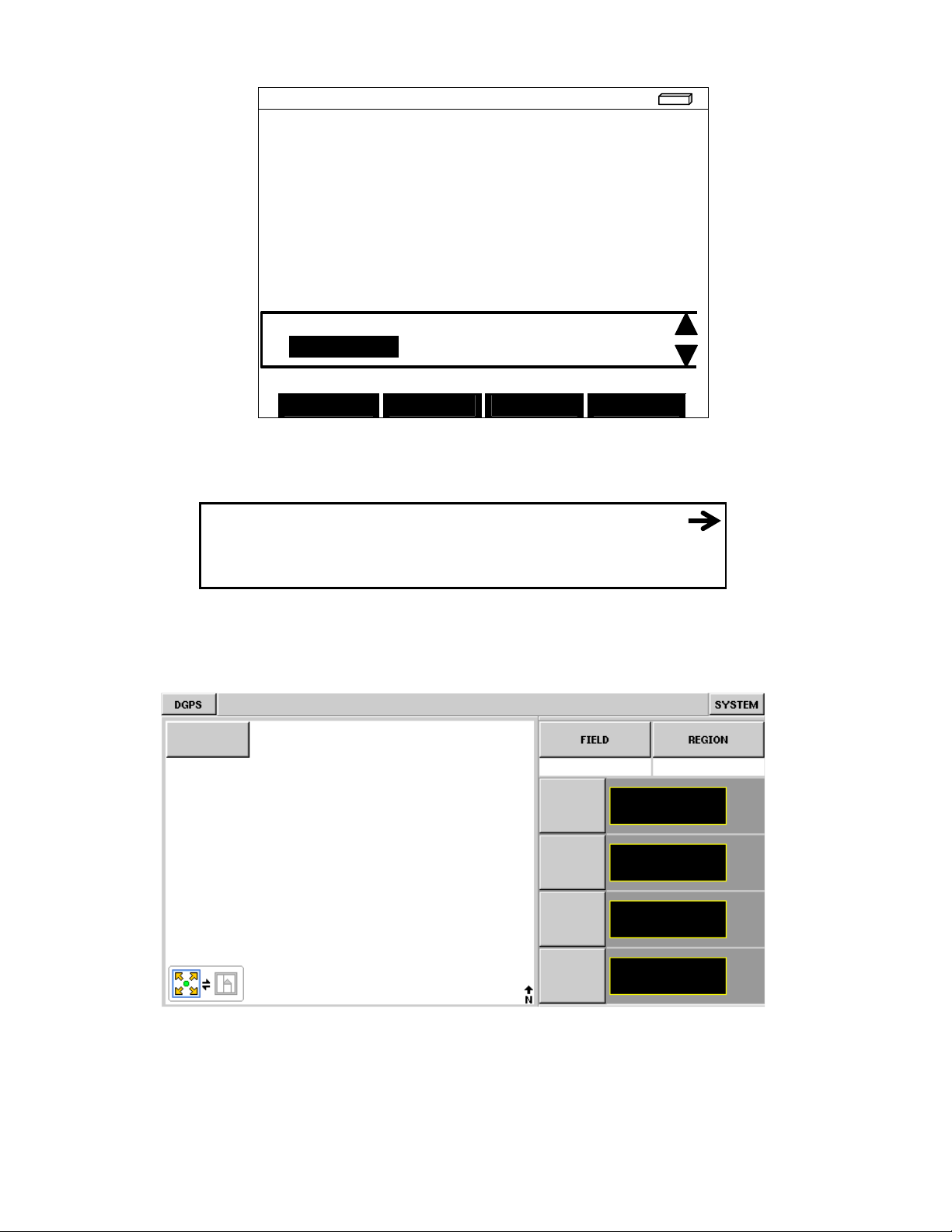
Figure 3. Insight run screen with DGPS displayed
6
3000021
Page 7

NMEA DIAGNOSTICS
Valid GGA and VTG strings…
$GPGGA,182118.00,4201.1377,N,09338.1416,W,2,0
General
Information
To view NMEA messages on the PF3000:
Press MENU key until DIAG is displayed and press the DIAG key.
On the DIAGNOSTIC SELECTIONS screen press the RAW NMEA key
to view the GGA and VTG strings.
8,0.9,276.05,M,-31.54,M,5.4,0166*7F
$GPVTG,168.7,T,,,000.13,N,000.25,K*20
$GPGGA,182119.00,4201.1377,N,09338.1414,W,2,0
8,0.9,275.97,M,-31.54,M,4.0,0166*71
$GPVTG,96.5,T,,,000.73,N,001.35,K*14
$GPGGA,182120.00,4201.1377,N,09338.1409,W,2,0
8,0.9,275.89,M,-31.54,M,5.0,0166*79
$GPVTG,90.4,T,,,002.94,N,005.44,K*1A
LOAD EXIT
Figure 4. PF3000 screen showing NMEA message string.
3000021
7
Page 8

Using
GPS1000/GPS1000+/
GPS1100
Plus
Utility Version 1.1
The GPS1000/GPS1000+/GPS1100 is pre-set at the factory to work
with an Ag Leader yield monitor system. Other applications may
require special message settings, which can be changed with this
utility. Refer to the documentation for your software application and/or
hardware to determine its required baud rate, NMEA messages and Hz
output rate.
1. Connect the GPS1000/GPS1000+/GPS1100 to a computer using
either the Ag Leader GPS1000/GPS1000+/GPS1100 Mobile
Logging or GPS1000/GPS1000+/GPS1100 Auxiliary Power/Data
cable.
2. Insert the Ag Leader SMS CD into the computer CD-ROM drive.
3. The CD Menu will now appear. Click on "Browse CD," then the
“Misc Folder,” now the GPS 1100 folder will now appear.
4. Click on the "Connect" button below, then select the COM port and
the baud rate for the computer that you are connected to. The
correct baud rate should be 4800 unless you have previously
changed it on the GPS1000/GPS1000+/GPS1100.
5. The Messages tab will now be displayed. Once you have specified
the desired settings, click the "Send Settings" button to send the
changes to the GPS1000/GPS1000+/GPS1100.
6. If you are going to be using the GPS 1100 for Direct Command
application, you will need to configure the GPS 1100 for a baud
rate of 19200, 4hz output rate
NOTE: The Messages tab does not display the current
configuration of the GPS1000/GPS1000+/GPS1100, only the
setting options that are available and the recommended factory
defaults.
7. The Serial Data tab will now appear and the selected NMEA
messages should now be scrolling down the screen as they are
output from the GPS1000/GPS1000+/GPS1100. Click pause to
stop the message sending for easier viewing.
8. Click on Exit to finish.
8
3000021
Page 9

Antenna
Installation
Installing the
Antenna on
Combine or
Tractor
Installing with antenna magnet:
The following parts and tools are needed to install the antenna and
bracket:
• 5/16 in. self tapping bolts • L-bracket
or 5/16 in. bolts with serrated nuts • Antenna/Receiver
• 1/4 in. drill bit for thin metal • Marker
or 9/32 in. for thicker metal • Punch
• Power/Data Cable
• Three white cable tie-downs
with self tapping screws
• Three white cable tie-downs
The antenna magnet is very powerful and will stick securely to any metal
surface. If needed, an L-bracket for mounting the antenna is provided.
The L-bracket is used for mounting the antenna (especially on combines)
but not necessary.
Determine a mounting location that is in the center of the swath and the
highest point of the vehicle. Ensure that no part of the machine is
blocking a clear view of the sky to the antenna. Ensure the antenna is
mounted low enough so it won't be knocked off when pulling the vehicle
into the shed. Find a mounting location that if it does get struck it can
slide off.
1 Locate a flat metal surface on the vehicle; set the antenna
on it ensuring the magnet adheres securely.
2 Ensure you leave some slack in the cable between the
antenna connection and first tie down. Route cable to cab
using cable tie-downs every 12-18 inches to secure cable.
Installing antenna with L-bracket:
1 Place the top surface of the bracket 1/4-in. above the top of
the highest metal surface of the vehicle. This ensures the
antenna is the highest point of the vehicle and can slide off
if struck.
3000021
9
Page 10

Routing the Cable
to the Cab
2 After you determine this position, place the L-bracket against
the metal surface, mark and punch the places you will be
drilling.
3 Drill the holes in the surface and attach bracket as follows:
If the metal is … Then use a…
Thin 1/4-in. drill bit and 5/16 in.
bolts with serrated nuts.
Thick (1/8 in. or more) 9/32 in. bit and self-tapping
bolt.
4 Center the antenna on the top surface of the bracket.
5 Attach the cable to antenna, connecting the end with the plug
to antenna.
6 Attach a white cable tie-down to metal surface 1 or 2 ft
below and 6 in. to right of the L-bracket.
NOTE: You may need to increase the above
distances, depending on the type of grain tank
extension you are using.
7 Place another white tie-down 3 to 5 ft to the right of the first
tie-down.
8 Use a cable tie and attach the cable to the first white tie-
down leaving some slack in cable between antenna
connection and tie down to allow for strain relief if the
antenna is knocked off the L-bracket.
9 Use another cable tie to attach the cable to the second tie-
down.
10 Route cable to cab using cable tie-downs to secure cable.
Follow these steps to route cable into the cab:
1 Find a place on the right side or bottom of the cab to route
cable into cab (the point of entry is up to you).
IMPORTANT: The cable can be routed through
windows or doors but make sure that there will be
no damage to the cable.
2 Attach the GPS cable from the antenna to Port 1 of the
PF3000, Port 1 on the YM 2000, or the GPS port on the
Insight. See Figures 4 and 5.
10
3000021
Page 11

NOTE: If you are attaching the
GPS1000/GPS1000+/GPS1100 to a PF 3000 Pro
without GPS, attach the GPS cable to AUX. 1 Port.
NOTE: If you are connecting your
GPS1000/GPS1000+/GPS1100 to an alternative
logging or mapping device (i.e. handheld or laptop
computer), refer to your Operator's Manual for that
particular unit for correct cable connection.
Figure 5. Cable attachment for PF3000 and GPS1000/GPS1000+/GPS1100
Figure 6. Cable attachment for YM 2000 and GPS1000/GPS1000+/GPS1100
Figure 7. Cable attachment for Insight and GPS1000/GPS1000+/GPS1100
3000021
11
Page 12

Radar Speed
Output
Radar Speed
Compatibility
Radar Speed
Default Settings
The GPS1000+/GPS1100 is capable of outputting a simulated radar
speed pulse. This simulates a similar pulse output that you would receive
from a standard radar gun. The GPS1000+/GPS1100 provides the
capability to provide simulated radar speed to your YM2000, PF3000,
PF3000 Pro, PF Advantage, or Insight display. To use the radar speed
input with an Ag Leader display, you must set the speed input to
RADAR under the appropriate setup screen for the monitor/display.
Additional cables will also be required to obtain the simulated speed
output. Contact Ag Leader’s Technical support team for these additional
cables.
*NOTE – The GPS1000 is not capable of simulated radar speed output.
Adaptor cables are available through Ag Leader Technology for the
following three radar gun brands Dickey-John, Raven, and Hiniker.
These adaptor cables provide the ability to use the GPS1000+/GPS1100
in place of a radar gun. If using the GPS1000+/GPS1100 as a standalone antenna, you will need to obtain an Auxiliary Power/Data Cable,
GPS power supply cable listed on page 15, and the appropriate Radar
Speed Adaptor Cable.
The default output parameter provided in the GPS1000+/GPS1100 is a
minimum output speed of .5 MPH, meaning speed pulses will not be
output below this speed. The default radar pulse output rate is 45 Hz per
MPH.
Radar Speed Adaptor Cable Name Part Number
Hiniker adaptor cable 3000478
Raven adaptor cable 3000479
Dickey John adaptor cable 3000480
12
3000021
Page 13

Specifications
Environmental
Physical
Specifications
Receiver
Specifications
Data
Input/Output
Specification
Operating Temp: -40C to +85 C
Humidity: 99% condensing
Size: 5.5 in. H x 5.0 in. W x 2.1 in. D
Weight Under 12 oz
Power: 9 to 16 VDC
Power Consumption: Less than 200 mA
Connector: 7-pin circular
GPS Engine: 10 Channel L1 C/A and WAAS
Accuracy: WAAS Diff. – 2m RMS
GPS only – 4 m RMS
Update Rate: 1Hz or 4Hz
Cold Start Time: 120 seconds (DGPS)
• Data is output once per second
• NMEA-0183 output via RS232
• Output rate and parameters can be set from PC
• Default output of GGA and VTG NMEA messages. Other
possible output messages are: GLL, GSA, GSV, RMC, ZDA
3000021
13
Page 14

DUETCH
1
TXDA
RED
3
2
RXDA
BLACK
2
3
GND
GREEN
6
WHITE 2
4
BOO
T BROWN
CUT
5
RADAR
BLUE
N.C.
BLACK 1
6
+12V
WHITE
4
7
GND
ORANGE
5
DUETCH
1 TXDA
RED
14
2 RXDA
BLACK
13
3 GND
GREE
N 5 WHITE 2
4 BOOT
BROWN
CUT
5 RADAR
BLUE
N.C.
BLACK 1
6 +12V
WHITE
10
7 GND
ORANGE
11
1 TXDA
RED
2
2 RXDA
BLACK
3
3 GND
GREEN
5
WHITE 2
4 BOOT
BROWN
CUT
4 RADAR
BLUE
BLACK 1
6 +12V
WHITE
WHITE 1
7 GND
ORANGE
BLACK 2
Cable Pinouts
for YM 2000,
PF 3000 &
Insight
PN 3000474
Cable Pinouts
for PF PRO/ PF
Advantage
PN 3000477
Cable
Pinouts
CONXALL
Connector
for Mobile
Logging
PN
3000475
CONXALL
Connector
CONXALL
Connector
SIGNAL COLOR DB9
SIGNAL COLOR DB9
Connector
SIGNAL COLOR HDB15
Connector
DUETCH
Connector
2-Pin
RADAR
2-Pin
RADAR
2-Pin
RADAR
CIGARETTE
Plug
14
3000021
Page 15

Configuration
Setup
Refer to the General Instructions section, Using GPS1000/GPS1000+/GPS1100
Utility Version 1.1; install the GPS1000/GPS1000+/GPS1100 Utility on your
personal computer.
Step-by-Step
Procedure
1. Double click on the GPS1000/GPS1000+/GPS1100 Utility icon.
2. Click "Connect" button
3. Select appropriate Com Port.
4. Verify a Baud Rate of 4800 and click the "O.K." button.
5. Select the appropriate value under Rate column as shown below.
RATE MESSAGE NAME
1 $GPGGA
OFF $GPGLL
1 $GPGSA
OFF $GPGSV
1 $GPRMC
OFF $GPVTG
OFF $GPZDA
6. Baud rate setting is dependent on the firmware version used on the processor.
Set the required Baud Rate.
Firmware Baud Rate
5.3P 9600
5.3R 4800
6.32F 4800
7. Click "Send Configuration" button.
8. A new screen for Serial Data should now appear.
9. Verify the serial data strings appear beginning with:
$GPGSA……………
$GPRMC……………
$GPGGA……………
10. If the serial data strings are incorrect repeat Steps 5 through 8.
11. Configuration is now complete. Click "Exit" button.
3000021
15
Page 16

Cable
Installation
Step-by-Step
Procedure for
Display
Mounted Mobile
Processor
3. Locate position "C" on same gray connector. The wire should be black and
The cable installation described here is for the Display mounted Mobile
Processor and Silver Wedge-Box Mobile Processor.
1. Locate gray 10-position connector on the GreenStar mapping processor and
find position "F". The wire should be a light blue color and be labeled
"232RXLD". If there is no wire in position “F”, insert the blue wire included
in the cable kit.
2. Install Blue splice 4 inches from gray connector. See Figure 1.
Figure 1. Installing Blue splice on wire 232RXLD
labeled "050B".
4. Install Blue splice 4 inches from gray connector. See Figure 2.
16
3000021
Page 17

Figure 2. Installing Blue splice on wire 050B
5. Connect blue terminals on adapter cable P.N. 2000998 to splices installed in
Step 2, in the following order (See Figure 3):
Black – Black
Blue – Light Blue
Figure 3. Adapter cable installed.
3000021
17
Page 18

6. Tuck blue and black wires back into the corrugation of original harness.
Have the 9-pin connector come out near the gray 10-position connector.
Replace cable ties as necessary. See Figure 4.
Figure 4. Cable corrugation back in place.
7. Connect 9 pin D-Sub connectors of P.N. 2000998 and P.N. 3000475 or
3000476. See Figure 5.
Figure 5. 9-Pin connector attached.
18
3000021
Page 19

Step-by-Step
Procedure for
Silver WedgeBox Mobile
Processor.
8. Hook-up appropriate power connection.
9. Run antenna end of cable to appropriate locations and tie down where
necessary.
10. Verify operation on monitor's GPS display.
_________________________________________________________________
1. Locate wire bundle coming out of Silver Processor and expose wires.
2. Find wire labeled "CC967" (wire should be orange) and install splice
connector 4 inches from processor.
3. Find wire labeled "CC20" (wire should be black) and install splice connector
6 inches from processor.
4. Using adapter cable P.N. 2000998, connect terminal on blue wire to splice on
orange wire labeled "CC967".
5. Connect terminal on black wire to splice on black wire labeled "CC20".
6. Tuck blue and black wires back into the corrugation of original harness.
Have the 9-pin connector come out near the processor. Replace cable ties as
necessary.
7. Connect 9 pin D-Sub connectors of P.N. 2000998 and P.N. 3000475 or
3000476.
8. Hook-up appropriate power connection.
9. Run antenna end of cable to appropriate locations and tie down where
necessary.
10. Verify operation on monitor's GPS display.
3000021
19
Page 20

•
•
•
•
Troubleshooting
Problem Cause Solution
I lose "D" around
buildings when using
WAAS Differential
I'm connected to the
GPS1000/GPS1000+
GPS1100 but am not
getting position data.
The following is a list of problems that you may encounter with the
GPS1000/GPS1000+/GPS1100 and suggestions for troubleshooting. If
you have a problem with the system, please review the list before calling
Ag Leader Technology. If your troubleshooting does not solve the
problem, please call Technical Support at Ag Leader Technology (515232-5363 ext. 1).
WAAS signal isn't
being transmitted.
• The WAAS
satellite you are
using is being
blocked.
Go to Raytheon’s website
(wwws.raytheontands.com/waas)
and check the current status of
WAAS transmission.
• There are only two (2) WAAS
satellites that are low on the East
and West horizon. Building and
tree lines can easily block the
signal.
Bad Cable or
dirty/wet connector
pins
• The output settings
of the GPS have
changed.
• No Power
• The GPS1000
GPS1000+
GPS1100 is
damaged.
Check to make sure the cable isn't
damaged and that the connector is
clean and dry.
• Connect the
GPS1000/GPS1000+/GPS1100 to
a PC using the Aux. Power/Data
cable and run the
GPS1000/GPS1000+/GPS1100
utilities program. Set the outputs
to what is required for your
operation.
• Verify that you are properly
connected to a power source.
• Call Ag Leader Technical
Support.
20
3000021
Page 21

Parts Name/Description
Part Number
Quantity
YM2000/PF3000/Insight System
4100505
1
Antenna Bracket – L shaped 2000161 1
Pro w/o GPS/PF Advantage System
4100506
1
Mobile Lo
gging System
4100507
1
OPT
IONAL CABLES
Auxiliary Power/Data Cable
3000476
GPS Power Supply Cable
2000825
GPS Tractor Battery Power Cable
2000827
-12
GPS Cigarette Light Power Cable
2000824
Antenna Installation Kit (GPS 1100, GPS 4100)
2001310-2 1
SMS Basic/Advanced CD 2001606 1
GPS 1100 – Antenna /Receiver
Cable – YM2000/PF3000 to GPS 1100
Manual Insert – GPS 1100
3000518 1
3000474 1
3000021 1
Antenna Bracket - L shaped 200161 1
Antenna Installation Kit (GPS 1100, GPS 4100)
2001310-2 1
SMS Basic/Advanced CD 2001601 1
GPS 1100 – Antenna/Receiver
3000518 1
Cable – Pro w/o GPS/ PF Advantage 3000477 1
Manual Insert – GPS 1100
3000021 1
Antenna Installation Kit (GPS 1100, GPS 4100)
2001310-2 1
SMS Basic/Advanced CD 2001606 1
GPS 1100 – Antenna /Receiver 3000518 1
Cable – Cigarette Power/Data (GPS 1100)
Manual Insert – GPS 1100
3000475 1
3000021 1
3000021
21
Page 22

Product Registration
Ag Leader Technology stands by all new products with a 2-year limited warranty from the warranty
start date. The warranty start date will initially be set to the date on which your product is shipped from
Ag Leader Technology
If you return this registration/warranty card within 30 days of purchasing this product from your dealer,
the warranty start date will be changed to the date that you purchased the product from your dealer.
Leader Technology
Timely product registration will allow you to receive important product bulletins, upgrade information,
and notice regarding product training in your area.
(Click on Product Registration from the Quick Links list on the Ag Leader Home Page.)
Return this sheet in the enclosed postage-paid envelope or by fax.
.
reserves the right to request proof of the date of purchase stated.
Register On-Line at www.agleader.com
OR
515-232-3595 - fax
Ag Leader Technology
2202 South Riverside Drive
P.O. Box 2348
Ames, Iowa 50010
Ag
Name: _______________________________________________________________________________________
Street Address: ______________________________________________________________________________
City, State, ZIP: ______________________________________________________________________________
Phone # (including area code): ________________________________________________________________
Mobile Phone #: ________________________ Fax #: _________________________________________
Email address:________________________________________________________________________________
Ag Leader Dealer:_____________________________________________________________________________
Date Purchased
Monitor Serial #: _______________________ Flow Sensor Serial #: _________________________________
GPS Antenna Serial #:__________________ Elevator Mount Serial #:______________________________
Light Bar Serial #:_________________________ Key Pad Serial #:___________________________________
:_____________________________________________________________________________
Combine Model #: ________________ Combine Serial #: _________________________________________
22
3000021
Page 23

Summary of Changes for 3000021
December, 2003 Initial Release of GPS 1000 Manual Insert.
February, 2004 Updated registration form
January, 2006 Updated to GPS 1100 Manual Insert
3000021
23
 Loading...