

Page 1
GPS 1000 Plus
Ag Leader Technology
Configuration
Setup
Step-by-Step
Procedure
Refer to the GPS 1000 Plus General Instructions section, Using GPS 1000 Plus
Utility Version 1.1 on page 5, and install the GPS 1000 Plus utility on your
personal computer.
1. Double click on the GPS 1000 Plus Utility icon.
2. Click "Connect" button
3. Select appropriate Com Port.
4. Verify a Baud Rate of 4800 and click the "O.K." button.
5. Select the appropriate value under Rate column as shown below.
6. Baud rate setting is dependent on the firmware version used on the processor.
Set the required Baud Rate.
7. Click "Send Configuration" button.
8. A new screen for Serial Data should now appear.
9. Verify the serial data strings appear beginning with:
$GPGSA……………
$GPRMC……………
$GPGGA……………
10. If the serial data strings are incorrect repeat Steps 5 through 8.
11. Configuration is now complete. Click "Exit" button.
Installation on GreenStar™ Monitors
RATE MESSAGE NAME
1 $GPGGA
OFF $GPGLL
1 $GPGSA
OFF $GPGSV
1 $GPRMC
OFF $GPVTG
OFF $GPZDA
Firmware Baud Rate
5.3P 9600
5.3R 4800
6.32F 4800
December 2003 2005638 1
Page 2
Installation on GreenStar™ Monitors
GPS 1000 Plus
Ag Leader Technology
Cable
Installation
Step-by-Step
Procedure for
Display
Mounted Mobile
Processor
The cable installation described here is for the Display mounted Mobile
Processor and Silver Wedge-Box Mobile Processor.
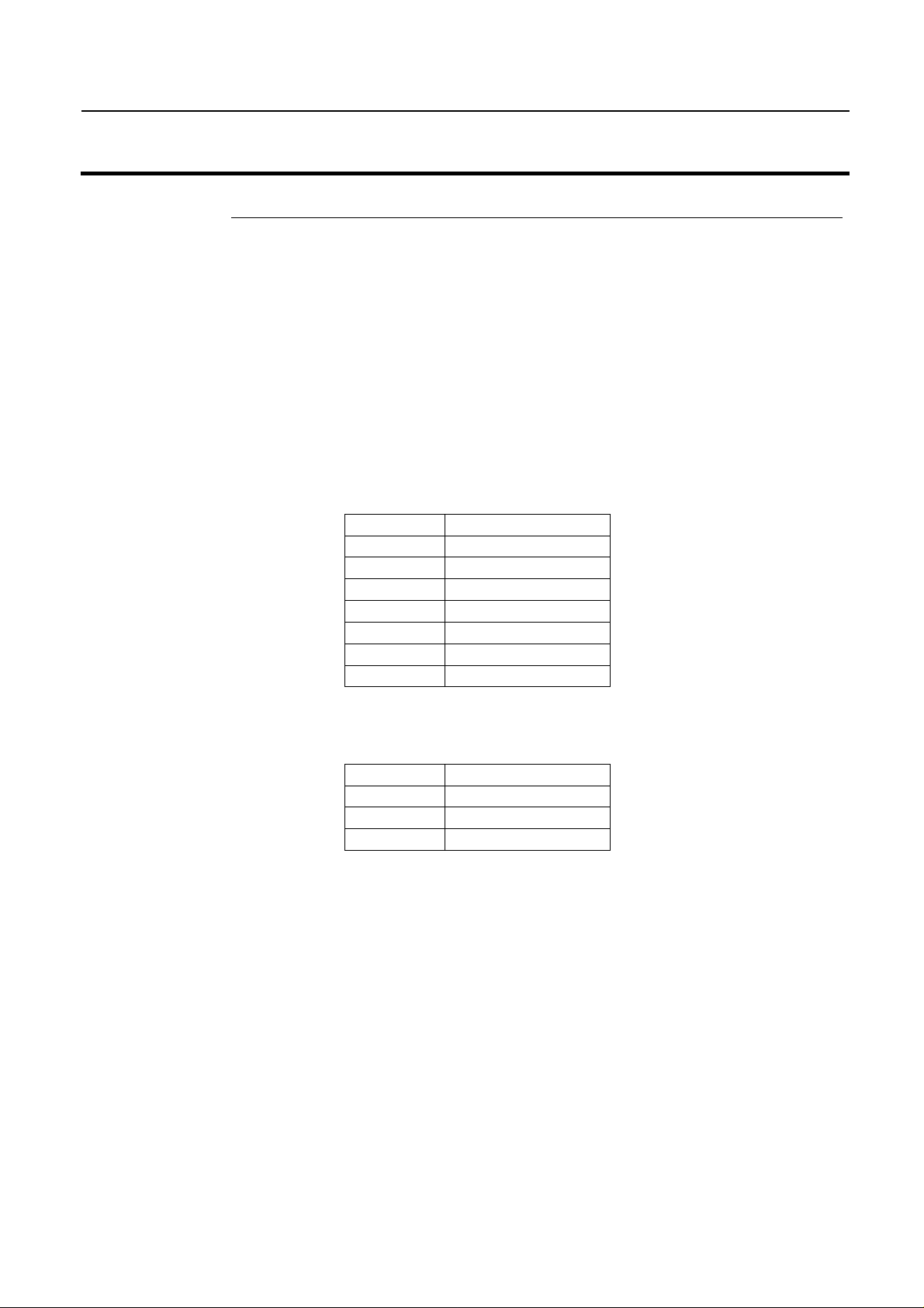
1. Locate gray 10 position connector on the GreenStar mapping processor and
find position "F". The wire should be a light blue color and be labeled
"232RXLD". If there is no wire in position “F”, insert the blue wire included
in the cable kit.
2. Install Blue splice 4 inches from gray connector. See Figure 1.
Figure 1. Installing Blue splice on wire 232RXLD
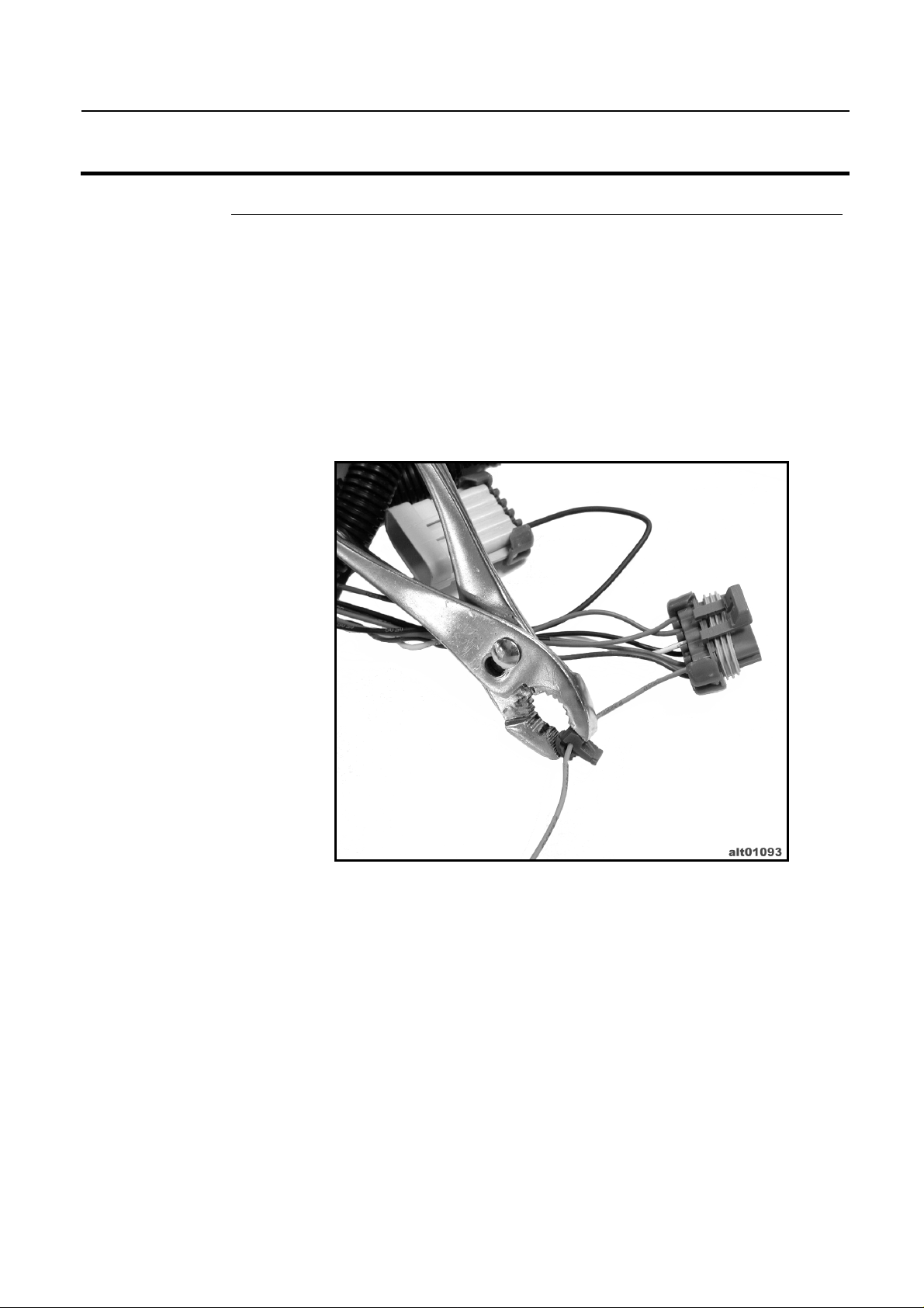
3. Locate position "C" on same gray connector. The wire should be black and
labeled "050B".
4. Install Blue splice 4 inches from gray connector. See Figure 2.
December 2003 2005638 2
Page 3
GPS 1000 Plus
Ag Leader Technology
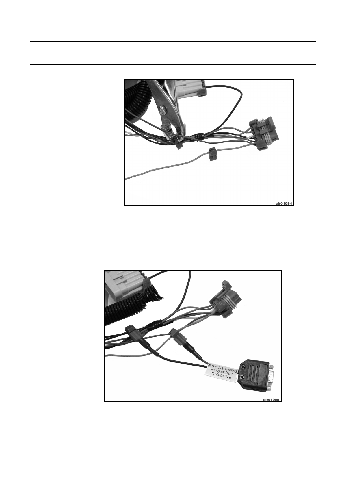
5. Connect blue terminals on adapter cable P.N. 2000998 to splices installed in
Step 2, in the following order (See Figure 3):
Black – Black
Blue – Light Blue
Installation on GreenStar™ Monitors
Figure 2. Installing Blue splice on wire 050B
Figure 3. Adapter cable installed.
December 2003 2005638 3
Page 4

Installation on GreenStar™ Monitors
GPS 1000 Plus
Ag Leader Technology
6. Tuck blue and black wire's back into the corrugation of original harness.
Have the 9 pin connector come out near the gray 10 position connector.
Replace cable ties as necessary. See Figure 4.
Figure 4. Cable corrugation back in place.
7. Connect 9 pin D-Sub connectors of P.N. 2000998 and P.N. 3000475 or
3000476. See Figure 5.
Figure 5. 9-Pin connector attached.
December 2003 2005638 4
Page 5

GPS 1000 Plus
Ag Leader Technology
Step-by-Step
Procedure for
Silver WedgeBox Mobile
Processor.
8. Hook-up appropriate power connection.
9. Run antenna end of cable to appropriate locations and tie down where
necessary.
10. Verify operation on monitor's GPS display.
1. Locate wire bundle coming out of Silver Processor and expose wires.
2. Find wire labeled "CC967" (wire should be orange) and install splice
connector 4 inches from processor.
3. Find wire labeled "CC20" (wire should be black)and install splice connector 6
inches from processor.
4. Using adapter cable P.N. 2000998, connect terminal on blue wire to splice on
orange wire labeled "CC967".
5. Connect terminal on black wire to splice on black wire labeled "CC20".
6. Tuck blue and black wire's back into the corrugation of original harness.
Have the 9 pin connector come out near the processor. Replace cable ties as
necessary.
7. Connect 9 pin D-Sub connectors of P.N. 2000998 and P.N. 3000475 or
3000476.
8. Hook-up appropriate power connection.
9. Run antenna end of cable to appropriate locations and tie down where
necessary.
10. Verify operation on monitor's GPS display.
Installation on GreenStar™ Monitors
December 2003 2005638 5
Page 6

Page 7

GPS 1000 Plus
Ag Leader Technology
SUMMARY OF CHANGES
December, 2003 Initial release of this document.
Installation on GreenStar™ Monitors
Record of Changes
December 2003 2005638 7
 Loading...