

Page 1

GPS 1000
INSTALLATION
AND
GENERAL INSTRUCTIONS
April 2001 3000021
Page 2

Page 3

GPS 1000 Contents
1
Ag Leader Technology
Important Notices
Before beginning installation of your GPS 1000, please take the time to
thoroughly read these instructions. Signal words (CAUTION,
IMPORTANT, and NOTE) are provided to draw attention to
information that is important for the safe/correct installation and
operation of this product.
• CAUTION--will alert you to situations that will impact the
physical safety of you or others.
• IMPORTANT—will alert you to the potential for damage to the
product or loss of data.
• NOTE--will provide you with additional information to simplify a
procedure or clarify a process.
After completing installation of the GPS 1000 we recommend that you
place these instructions in the Options Section of your YM 2000,
PF3000 or PF3000 Pro Operator’s Manual to prevent their loss.
To receive upgrade/update information of this product you must send
in or fax the Registration Form. Refer to the Registration Form for
address and fax number.
Item Page
General Instructions 2
Product Overview 2
General Information 2
Using GPS 1000 Utility Version 1.0 5
Installing Antenna/Receiver 6
Parts, Tools for Antenna Installation 6
Installing the Antenna on Combine or Tractor 6
Routing the Cable to Cab 7
Other Cable Connections 9
Specifications 11
Troubleshooting 13
Parts List 14
GPS 1000 Owners Registration
April 2001 3000021
Page 4

General Instructions
2
GPS 1000
Ag Leader Technology
Product Overview
General
Information
The GPS 1000 is an all in the antenna DGPS receiver that provides
position data for operations that do not require sub-meter position
accuracy or guidance. The GPS 1000 utilizes differential correction from
the WAAS satellite differential system. The GPS 1000 provides 2-meter
accuracy when using WAAS differential and 4 meter accuracy without
any differential correction.
The GPS 1000 is a valuable addition for general data logging such as soil
sample collection, scouting, site verification or as a second GPS receiver
for yield mapping.
The GPS 1000 is weatherproof and protected against power surges that
are common on agricultural equipment. The GPS 1000 is also backed by
a 2-year warranty.
Wide Area Augmentation System (WAAS) differential correction is an
alternative to subscription based satellite differential correction.
IMPORTANT: WAAS is currently free of charge, and is
being funded by the Federal Aviation Administration (FAA).
WAAS is currently in test mode, and Ag Leader Technology
can not guarantee the availability or quality of its position
signals. Only two (2) WAAS satellites are currently covering
North America.
The GPS 1000 requires no initial setup to begin fieldwork. The PF3000,
(Figure 3) or YM 2000, (Figure 4) will display a "D" or "G" on the top
right hand corner of the display to indicate a GPS signal. A "D"
indicates that a differential signal is being received. A "G" indicates that
you have a GPS signal and your GPS receiver is tracking four or more
satellites (which means you can get an elevation reading). A lower case
"g" indicates that you have a GPS signal but your GPS receiver is
tracking only three satellites which means you can not get an elevation
reading. Your GPS receiver must track four or more satellites to get an
elevation reading.
The unit is defaulted to 4800-baud, 8, N, 1 output. One position is output
per second using GGA and VTG NMEA messages by default.
April 2001 3000021
Page 5
GPS 1000
3
Ag Leader Technology
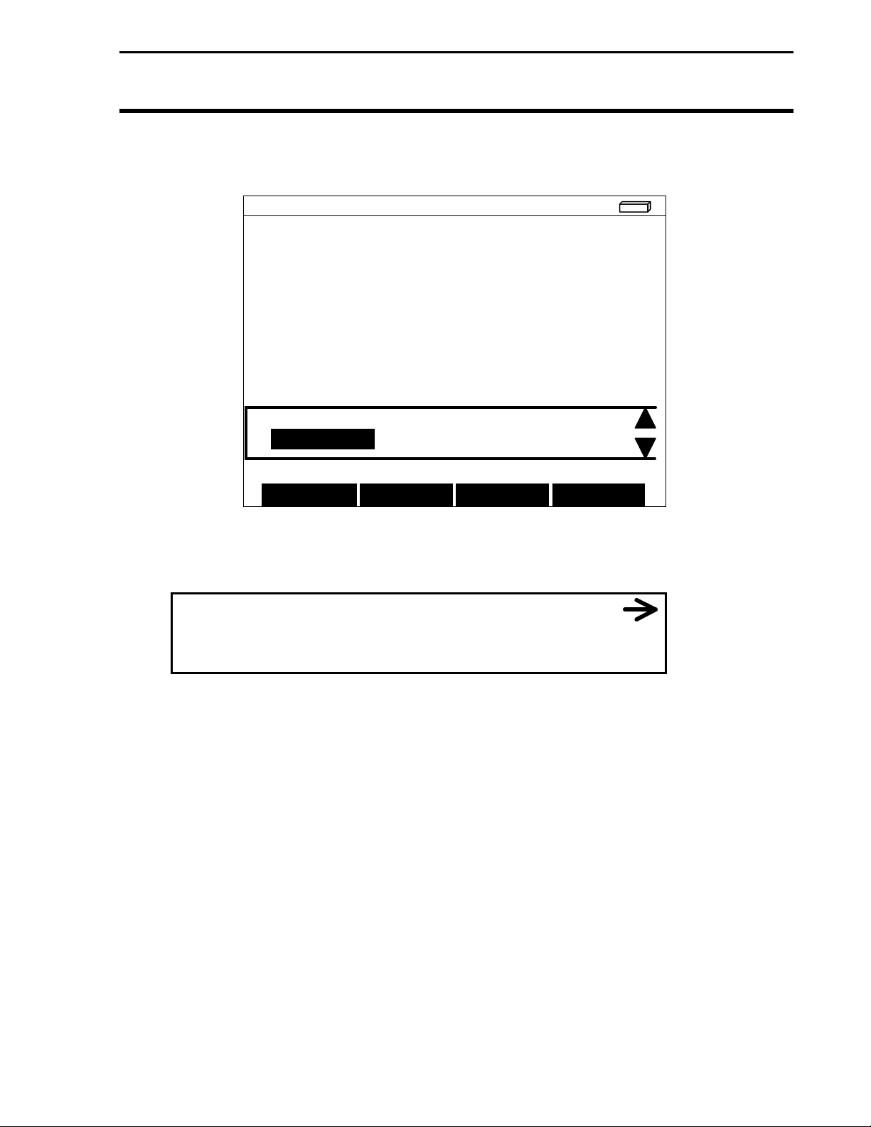
F1: HOME 40 L1: ENDS DG >
General Instructions
YIELD
44.3
MOISTURE
[auto man]
AREA
15.4
10.1
SWATH
< width rows >
Harvesting: CORN 1 AREA OFF
FIELD LOAD SHOW MAP OPTIONS
Figure 1. PF3000 screen with DG displayed
19 ft 0 in.
avg
bu/ac
avg
%
acres
F8: WEST 80 L4: 3417 DG
22.4 % 214 bu/ac
Figure 2. YM 2000 screen with DG displayed
April 2001 3000021
Page 6
General Instructions
4
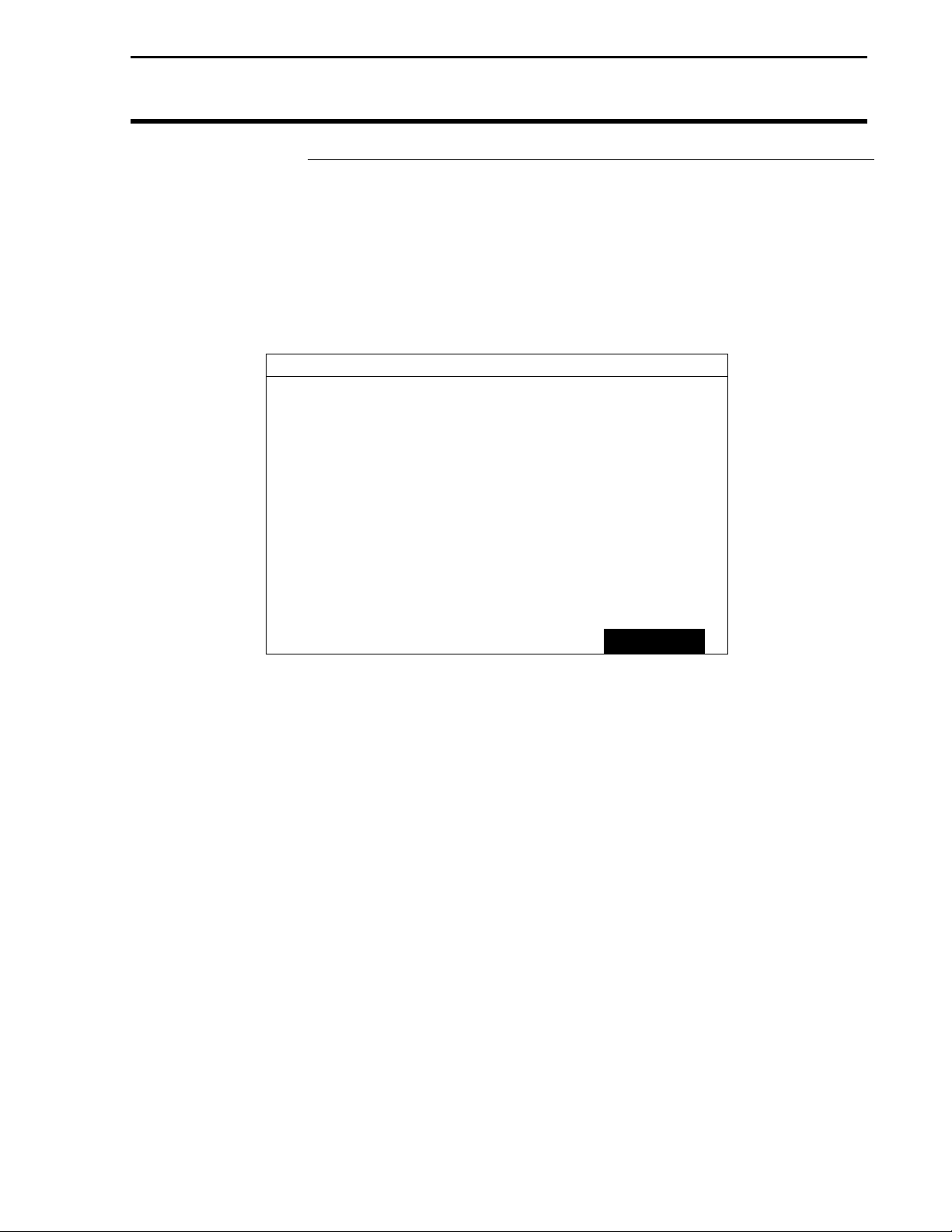
To view NMEA messages on the PF3000:
Press MENU key until DIAG is displayed and press the DIAG key.
On the DIAGNOSTIC SELECTIONS screen press the RAW NMEA key
to view the GGA and VTG strings. See Figure 8.
NMEA DIAGNOSTICS
Valid GGA and VTG strings…
$GPGGA,182118.00,4201.1377,N,09338.1416,W,2,0
8,0.9,276.05,M,-31.54,M,5.4,0166*7F
$GPVTG,168.7,T,,,000.13,N,000.25,K*20
$GPGGA,182119.00,4201.1377,N,09338.1414,W,2,0
8,0.9,275.97,M,-31.54,M,4.0,0166*71
$GPVTG,96.5,T,,,000.73,N,001.35,K*14
$GPGGA,182120.00,4201.1377,N,09338.1409,W,2,0
8,0.9,275.89,M,-31.54,M,5.0,0166*79
$GPVTG,90.4,T,,,002.94,N,005.44,K*1A
GPS 1000
Ag Leader Technology
LOAD EXIT
Figure 3. PF3000 screen showing NMEA message string.
April 2001 3000021
Page 7

GPS 1000
5
Ag Leader Technology
GPS 1000 Utility
Using GPS 1000
Utility Version 1.0
The GPS1000 is pre-set at the factory to work with an Ag Leader yield
monitor system. Other applications may require special message
settings which can be changed with this utility. Refer to the
documentation for your software application and/or hardware to
determine its required baud rate and NMEA messages.
1. Connect the GPS1000 to a computer using either the Ag Leader
GPS1000 Mobile Logging or GPS1000 Auxiliary Power/Data
cable.
2. Insert the Ag Leader Software Suite CD into the computer CD-
ROM drive.
3. The CD Menu will now appear. Click on "Start GPS 1000 Utility
Program." The GPS 1000 utility program will now start.
4. Click on the "Connect" button below, then select the COM port and
the baud rate for the computer that you are connected to. The
correct baud rate should be 4800 unless you have previously
changed it on the GPS 1000.
5. The Messages tab will now be displayed. Once you have specified
the desired settings, click the "Send Settings" button to send the
changes to the GPS1000.
NOTE: The Messages tab does not display the current
configuration of the GPS1000, only the setting options that are
available and the recommended factory defaults.
6. The Serial Data tab will now appear and the selected NMEA
messages should now be scrolling down the screen as they are
output from the GPS1000. Click pause to stop the message sending
for easier viewing.
7. Click on Exit to finish.
April 2001 3000021
Page 8

Installing Antenna/Receiver
6
GPS 1000
Ag Leader Technology
Parts, Tools for
Antenna
Installation
Installing the
Antenna on
Combine or
Tractor
The following parts and tools are needed to install the antenna and its
bracket:
• 5/16 in. self tapping bolts • L-bracket
or 5/16 in. bolts with serrated nuts • Antenna/Receiver
• 1/4 in. drill bit for thin metal • Marker
or 9/32 in. for thicker metal • Punch
• Power/Data Cable ? Hand drill
• Three white cable tie-downs
with self tapping screws
• Three white cable tie-downs
The antenna magnet is very powerful and will stick securely to any metal
surface. If needed, an L-bracket for mounting the antenna is provided.
The L-bracket is used for mounting the antenna (especially on combines)
but not necessary.
Determine a mounting location that is in the center of the swath and the
highest point of the vehicle. Ensure that no part of the machine is
blocking a clear view of the sky to the antenna. Ensure the antenna is
mounted low enough so it won't be knocked off when pulling the vehicle
into the shed. Find a mounting location that if it does get struck it can
slide off.
Installing with antenna magnet:
Step Action
1 Locate a flat metal surface on the vehicle; set the antenna
on it ensuring the magnet adheres securely.
2 Ensure you leave some slack in the cable between the
antenna connection and first tie down. Route cable to cab
using cable tie-downs every 12-18 inches to secure cable.
Installing antenna with L-bracket:
Step Action
1 Place the top surface of the bracket 1/4-in. above the top of
the highest metal surface of the vehicle. This ensures the
antenna is the highest point of the vehicle and can slide off
if struck.
April 2001 3000021
Page 9

GPS 1000
7
Ag Leader Technology
2 After you determine this position, place the L-bracket against
3
4 Center the antenna on the top surface of the bracket.
5 Attach the cable to antenna, connecting the end with the plug
6 Attach a white cable tie-down to metal surface 1 or 2 ft
7 Place another white tie-down 3 to 5 ft to the right of the first
8 Use a cable tie and attach the cable to the first white tie-
9 Use another cable tie to attach the cable to the second tie-
10 Route cable to cab using cable tie-downs to secure cable.
Installing Antenna/Receiver
the metal surface, mark and punch the places you will be
drilling.
Drill the holes in the surface and attach bracket as follows:
If the metal is … Then use a…
Thin 1/4-in. drill bit and 5/16 in.
bolts with serrated nuts.
Thick (1/8 in. or more) 9/32 in. bit and self-tapping
bolt.
to antenna.
below and 6 in. to right of the L-bracket.
NOTE: You may need to increase the above
distances, depending on the type of grain tank
extension you are using.
tie-down.
down leaving some slack in cable between antenna
connection and tie down to allow for strain relief if the
antenna is knocked off the L-bracket.
down.
Routing the Cable
Follow these steps to route cable into the cab:
to the Cab
Step Action
1 Find a place on the right side or bottom of the cab to route
cable into cab (the point of entry is up to you).
IMPORTANT: The cable can be routed through
windows or doors but make sure that there will be
no damage to the cable.
April 2001 3000021
Page 10

Installing Antenna/Receiver
8
Step Action
2 Attach the GPS cable from the antenna to Port 1 of the
GPS 1000
Ag Leader Technology
PF3000 or Port 1 on the YM 2000. See Figures 4 and 5.
NOTE: If you are attaching the GPS 1000 to a PF
3000 Pro without GPS, attach the GPS cable to
AUX. 1 Port.
NOTE: If you are connecting your GPS 1000 to an
alternative logging or mapping device (i.e.
handheld or laptop computer), refer to your
Operator's Manual for that particular unit for
correct cable connection.
Port 1
Figure 4. Cable attachment for PF3000 and GPS 1000
Port 1
Figure 5. Cable attachment for YM 2000 and GPS 1000
April 2001 3000021
Page 11

GPS 1000
9
Hand Held Device
PC
Data Cable
GPS 1000 Cable
Ag Leader Technology
Installing Antenna/Receiver
Other Cable
Connections
Refer to Figures 6 through 8 for some of the possible configurations to
attach the GPS 1000.
If you are not using an Ag Leader product refer to that product's Operator's
Manual to see how you verify GPS differential.
Step Action
Cable Attachment
1 Connect the GPS 1000 cable to the GPS 1000 receiver.
2 Attach Auxiliary Power Data cable to the GPS 1000 cable
3 Connect the GPS Power Supply to the male connector of the
pigtail on the Auxiliary Power Cable.
4 Connect the remaining single 9-pin connector from the Auxiliary
Power Data Cable to an open COM Port on the PC.
Auxiliary Power
Comm
Port
GPS Power Supply
Figure 6. Antenna to PC cable connection
Mobile Logging Cable
Figure 7. Cable attachment for Handheld GPS device
April 2001 3000021
Page 12

Installing Antenna/Receiver
10
GPS 1000 Cable
GPS 1000
Ag Leader Technology
Laptop PC
Auxiliary Power/Data Cable
GPS Tractor Battery Power Cable
Or
Cigarette Lighter Power Cable
(NOT SHOWN)
Figure 8. Cable attachment for Laptop PC.
April 2001 3000021
Page 13

GPS 1000
11
Ag Leader Technology
Specifications
Environmental
Specifications
Physical
Specifications
Receiver
Specifications
Operating Temp: -40C to +85 C
Humidity: 100% condensing
Size: 3.9 in. H x 2.7 in. D
Weight (w/o magnet): 10.2 oz (0.64 lbs)
(with magnet): 18.8 oz (1.18 lbs)
Power: 6 to 16 VDC
Power Consumption: Less than 0.2 Amps
Connector: 7-pin Conxall
GPS Engine: 12 Channel L1 C/A and WAAS
Accuracy: WAAS Diff. – 2m RMS
GPS only – 4 m RMS
Update Rate: 1Hz
Data
Input/Output
Specification
Cable Pinouts
for YM 2000
and PF3000
Cable
Cold Start Time: 120 seconds (DGPS)
• Data is output once per second
• NMEA-0183 output via RS232
• Output rate and parameters can be set from PC
• Default output of GGA and VTG NMEA messages. Other
possible output messages are: GLL, GSA, GSV, RMC, ZDA
CONXALL
Connector
1 TXDA RED 3
2 RXDA BLACK 2
3 GND GREEN 6
4 BOOT BROWN CUT
5 RXDB BLUE CUT
6 +12V WHITE 4
7 GND ORANGE 5
SIGNAL COLOR DB9
Connector
April 2001 3000021
Page 14

Specifications
12
GPS 1000
Ag Leader Technology
Cable Pinouts for
Mobile Cable
CONXALL
Connector
SIGNAL COLOR DB9
Connector
1 TXDA RED 1
2 RXDA BLACK 2
3 GND GREEN 3
4 4
5 5
6 +12V WHITE 6 WHITE
7 GND ORANGE 7 BLACK
Cigarette
Plug
April 2001 3000021
Page 15

GPS 1000
13
Ag Leader Technology
Troubleshooting
Troubleshooting
Problem Cause Solution
I lose "D" around
buildings when using
WAAS Differential
I'm connected to the
GPS 1000 but am not
getting position data.
The following is a list of problems that you may encounter with the GPS
1000 and suggestions for troubleshooting. If you have a problem with the
system, please review the list before calling Ag Leader Technology. If
your troubleshooting does not solve the problem, please call Technical
Support at Ag Leader Technology (515-232-5363 ext. 1).
• WAAS signal isn't
being transmitted.
• The WAAS
satellite you are
using is being
blocked.
• Bad Cable or
dirty/wet connector
pins
• The output settings
of the GPS have
changed.
• No Power
• The GPS 1000 is
damaged.
• Go to Raytheons website
(wwws.raytheontands.com/waas/)
and check the current status of
WAAS transmission.
• There are only two (2) WAAS
satellites that are low on the East
and West horizon. Building and
tree lines can easily block the
signal.
• Check to make sure the cable isn't
damaged and that the connector is
clean and dry.
• Connect the GPS 1000 to a PC
using the Aux. Power/Data cable
and run the GPS 1000 utilities
program. Set the outputs to what
is required for your operation.
• Verify that you are properly
connected to a power source.
• Call Ag Leader Technical
Support.
April 2001 3000021
Page 16

Parts List
14
GPS 1000
Ag Leader Technology
Parts Name/Description Part Number Quantity
YM2000/PF3000 System 3000420 1
Antenna Bracket – L shaped 2000161 1
Antenna Installation Kit (GPS 1000, GPS 4100 2001310-2 1
CD-ROM – Ag Leader Software Suite 2001601 1
SMS Basic CD w/Wallet 2001606 1
GPS 1000 – Antenna /Receiver 3000415 1
Cable – YM2000/PF3000 to GPS 1000 3000418 1
Manual Insert – GPS 1000 3000021 1
Mobile Logging System 3000424 1
Antenna Installation Kit (GPS 1000, GPS 4100 2001310-2 1
CD-ROM – Ag Leader Software Suite 2001601 1
SMS Basic CD w/Wallet 2001606 1
GPS 1000 – Antenna /Receiver 3000415 1
Cable – Cigarette Power/Data (GPS 1000) 3000415 1
Manual Insert – GPS 1000 3000021 1
OPTIONAL CABLES
Auxiliary Power/Data Cable 3000425
GPS Power Supply Cable 2000825
GPS Tractor Battery Power Cable 2000827-12
GPS Cigarette Light Power Cable 2000824
April 2001 3000021
Page 17

GPS 1000
Owners Registration
You will NOT receive upgrade/update information for this product if you are not
registered.
Return this sheet in the enclosed postage-paid envelope or by fax.
(Outside the USA 011) -1- 515-232-3595 - fax
Ag Leader Technology
2202 South Riverside Drive
P.O. Box 2348
Ames, Iowa 50010
Name: _______________________________________________________________________
Street Address: ______________________________________________________________
City, State, Country: __________________________________________________________
Postal or USA ZIP code: __________________________
Phone # (including Country code or USA area code):_____________________________
Mobile Phone #: ________________________ Fax #: __________________________
Email address:_______________________________________________________________
Ag Leader Dealer:____________________________________________________________
Dealer Address:___________________________________________________________________
Intended Use (Please circle all that apply): Combine Sprayer Planter ATV
Other, please specify____________________________________________
PF3000 Serial #: __________________
PF3000 Pro Serial #:________________
GPS 1000 Serial #___________________
Page 18

Page 19

GPS 1000
Ag Leader Technology
Summary of Changes for 3000021
March 23, 2001 Initial Release of this Manual Insert.
Revision Page
March 2001 3000021
 Loading...