

Page 1
200-0667-01 Kit
200-0667-02 Kit
200-0667-03 Kit
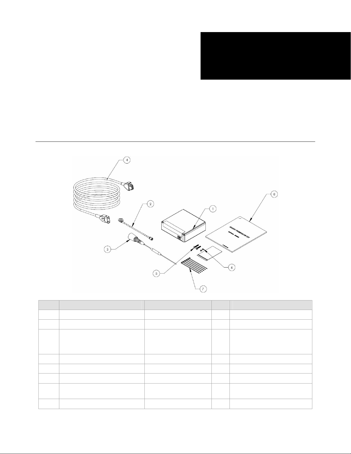
GeoSteer GS-450 Radio Kit
Item Component Part Number Qty Notes
1.
2.
3.
4.
5.
6.
7.
8.
Assembly, Radio GS-450 200-0666-01 1
Cable, RF Radio NMO 10" 201-0537-01 1
Antenna, 406-430 MHz 5DB NGP
Antenna, 430-450 MHz 5 DB NGP
Antenna, 450-470 MHz 5DB NGP
Cable, Power and Data Extension 201-0535-01 1
Screw, Pan-head M6 x 25mm SS 515-0120-01 2
Washer, Split Lock M6 517-0031-01 2
Cable Tie, 5-1/2" x 0.13" Black
Nylon
Installation Instructions 602-0307-01 1
500-0093-02
500-0094-02
500-0095-02
510-0078-01 20
1
Included antenna is specific to each
kit.
GS-450 Radio Kit Installation Instructions 602-0307-01 Rev A
Page 2

Kit Descriptions
This manual contains the instructions for the following kits:
•
200-0667-01: Kit, Radio, GS-450: 450-470 MHz
•
200-0667-02: Kit, Radio, GS-450: 430-450 MHz
•
200-0667-03: Kit, Radio, GS-450: 406-430 MHz
LEGAL DISCLAIMER
The manufacturer disclaims any liability for damage or injury that results from failure to follow the instructions and
warnings set forth herein.
Note: The installation procedures must be performed by an authorized, fully trained and certified dealer technician.
Note: Read and follow ALL instructions in this guide carefully before installing any hardware or operating the steering system.
Note: Take careful note of the information in the Safety Information section and throughout this guide.
Special Requirements
Tools
This list consists of the tools required to complete the installation. The installer is assumed to have a complete set of common
installation tools.
15/16” open wrench #3 Phillips screwdriver Cleaning rags
Hacksaw Ladder, 10 ft (3 m) Wire cutter small
Flat screwdriver 3/32" Allen wrench
Technical Support
Refer to your Display user manual for technical support information.
Contact Information
Refer to your Display user manual for contact information.
Copyright © 2012 All Rights Reserved
2 GS-450 Radio Kit Installation Instructions
Page 3
Safety and Regulatory Requirements
The GeoSteer system installer and manufacturer disclaim any responsibility for damage or physical harm caused by failure to
adhere to the following requirements:
•
• The GeoSteer system must be operated by a trained and qualified operator.
•
• The operator must never leave the vehicle while the GeoSteer system is engaged.
•
• The GeoSteer system is not designed to replace the vehicle operator.
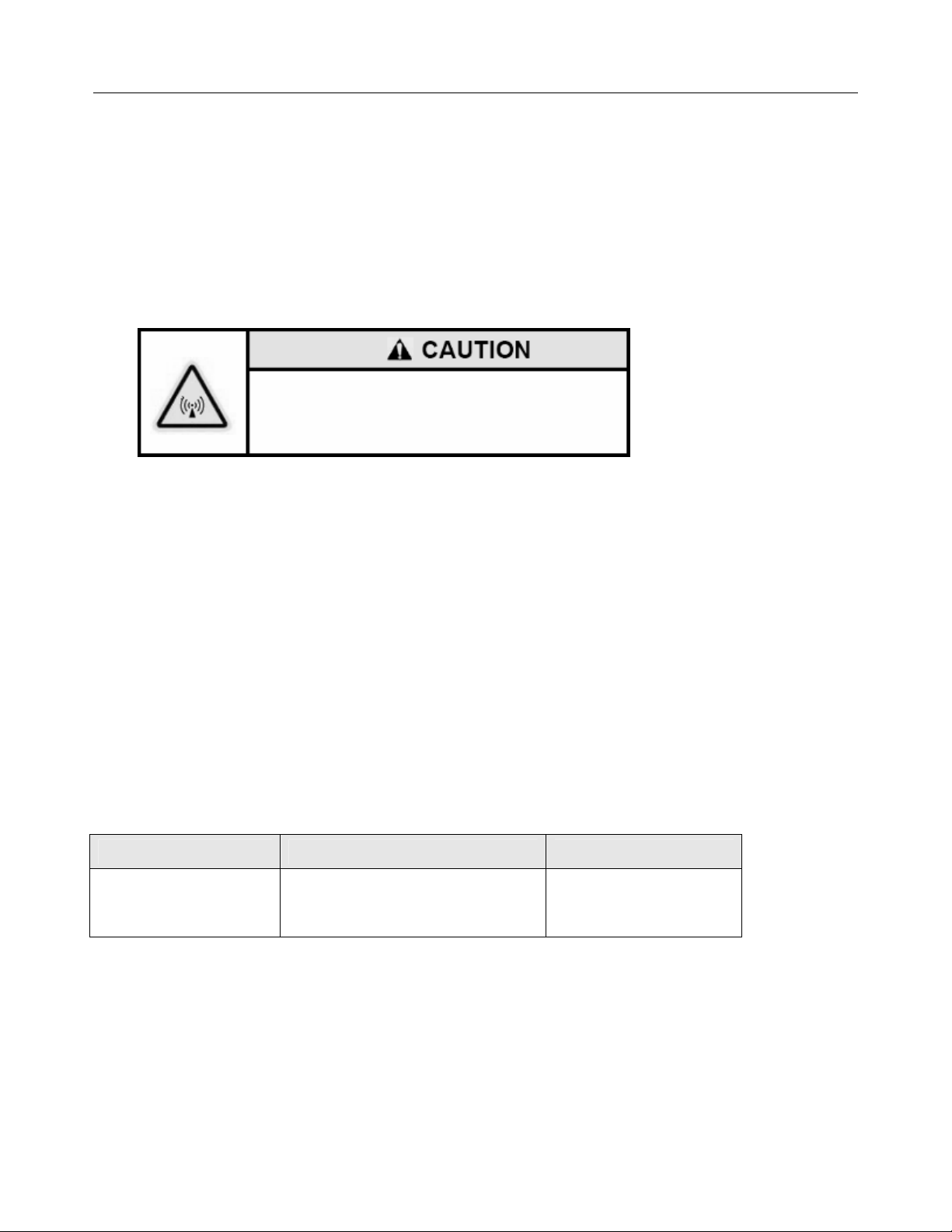
RF Exposure Information
FCC RF Exposure Requirements
The antennas connected to the radio must be mounted at
least 26.6 cm away from nearby persons to comply to FCC
RF exposure requirements
Configurations using radio modules not described above or which use antennas not qualified for the radio modules above
require further equipment authorization.
Regulatory Information
This device complies with Part 15 of the FCC Rules. This device shall be professionally installed and maintained by a trained
technician as directed by FCC regulations. Use of an antenna other than that outlined in the FCC and IC certification filings for
each of the radio products may violate FCC regulations. This device operation is subject to the following two conditions:
1. It may not cause harmful interference.
2. It must accept any interference received, including interference that may cause undesired operation.
It is your responsibility to certify that your radio transmitter is operating legally on an authorized frequency in your country
and locality. Contact your local government telecommunications authority to obtain information on licensing requirements and
request an operating license. Failure to operate on an authorized frequency will cause harmful radio interference to other radio
users and possible disruptions of important radio services. Failure to operate a radio transmitting device such as a base station
with the appropriate license may result in prosecution and severe penalties.
Table 1 Regulatory Information for this Radio Device
Manufacturer Description Regulation ID
MRB-SATELTA10
SATEL Modem Receiver 403-473 MHz
(2422A-SATELTA10)
[CE 0523]
GS-450 Radio Kit Installation Instructions 3
Page 4

Overview
The GS-450 Radio Modem provides a RTK radio link between the GeoSteer system on the vehicle and a local Base Station
transmitting on the same frequency. This manual provides the instructions for installing the GS-450 Radio Kit onto the
GeoDock of the GeoSteer system. Follow the instructions provided to install this kit.
Procedure
1. Turn off the GeoSteer system, disconnect the RF cables
from the GeoDock and remove the GeoDock from the
vehicle.
_____________________________________________
Note: The GeoSteer system must always be turned off
before connecting or disconnecting cables.
____________________________________________
2. Remove the black, plastic plug from rear of the GeoDock
assembly with a flat screwdriver.
3. Remove outer steel threaded ring from the RF Radio NMO
10"cable (PN 201-0537-01).
Note: There is an o-ring on the bottom side of the steel
ring. Verify that the o-ring is not lost.
4 GS-450 Radio Kit Installation Instructions
Page 5

4. Feed the RF Radio NMO 10" cable through the top of the
GeoDock assembly and then out the rear next the existing
cables.
5. Secure the RF Radio NMO 10" cable with the threaded
ring removed earlier.
6. Tighten with a 15/16" wrench.
7. Attach the GS-450 Radio Assembly to the bottom of the
GeoDock assembly using two M6 x 25mm screws.
8. Tighten the screws with a #3 Philips screwdriver.
GS-450 Radio Kit Installation Instructions 5
Page 6

9. Attach the RF Radio NMO 10" cable assembly to the TNC
connector on the GS-450 radio.
Note: Hand tighten only. Do not over tighten.
10. Refer to the antenna sizing information in the next section
to determine if the antenna needs to be cut for the desired
operation frequency. If it does not, skip to step 14.
11. Loosen the two set screws at the base of the antenna using a
3/32" Allen wrench, and then remove the antenna from the
base
12. Measure antenna and make the proper length using the
diagram next to Table 1-2 as a guide. Cut the end using a
hacksaw.
13. Reinstall antenna and tighten set screws using 3/32" Allen
wrench.
14. Attach antenna to RF Radio NMO 10" cable assembly’s
threaded base.
Note: Hand tighten only. Do not over tighten.
6 GS-450 Radio Kit Installation Instructions
Page 7

15. Attach the GeoDock assembly to the GeoDock Mounting
Plate on top of the vehicle.
Note: The GeoSteer system must always be turned off
before connecting or disconnecting cables.
Note: If this is the initial GeoSteer install, refer to the
GeoSteer installation manual for proper installation
procedures.
16. Attach the Power and Data Extension Cable (PN 201-0535-
01) to the rear of the GS-450 radio assembly. The
connectors have keys and will only engage in the correct
orientation. If the connector does not engage, check the
orientation. To avoid possible damage, never force the
connector.
Note: To disconnect the cable from the radio, press the two
side latches on the cable connector and pull away from the
radio.
17. Route Power and Data Extension Cable with the GeoSteer
coaxial cables running to the GeoSteer Control Unit.
18. Bundle the cables together every 12” (30cm) using the
cable ties provided. Use a wire cutter to trim.
GS-450 Radio Kit Installation Instructions 7
Page 8

19. Attach the Power and Data Extension Cable to the
EXPANSION connector of the GeoSteer Main Cable
Harness.
Note: In order for the GS-450 Radio to receive a correction signal, it must be set to the matching frequency of its intended base
station. Refer to the GeoSteer User Manual for instructions on setting the radio channel.
Antenna Sizing Information
Before use, the antenna may need to be cut to the proper size for the intended operation frequency. Refer to the table below for
proper antenna sizes.
Table 1-1 UHF 406-430 MHz Antennas (500-0093-02)
406-430 MHz
No Cutting Necessary
Table 1-2UHF 430-450 MHz Antennas (500-0094-02)
MHz Inches mm
430 12.750 324
435 12.188 310
440 11.625 295
445 11.000 279
450 10.563 268
Table 1-3UHF 450-470 MHz Antennas (500-0095-02)
MHz Inches mm
450 10.000 254
455 9.625 244
460 9.188 233
465 8.938 227
470 8.563 217
8 GS-450 Radio Kit Installation Instructions
Page 9

LED Diagnostics
During normal operation, the LED should be steady green and blink orange about once every second. If LED is steady green
but not blinking orange, it means that the unit is powered up but is not communicating with the Base Station. If the unit is not
communicating with the Base Station, check the frequency of both the GS-450 radio and the radio modem on the Base Station
which should be the same number. Refer to your GeoSteer user manual and Base Station user manual for instructions on how
to verify and, if necessary, change the channel number.
GS-450 Radio Kit Installation Instructions 9
 Loading...