

Agilent Technologies PTS03001UNIVUK, PTS03001UNIV, PTS03001UNIVEU, PTS03003UNIV, PTS03101UNIV Installation And Operating Manual
...Page 1

Vacuum Products Division
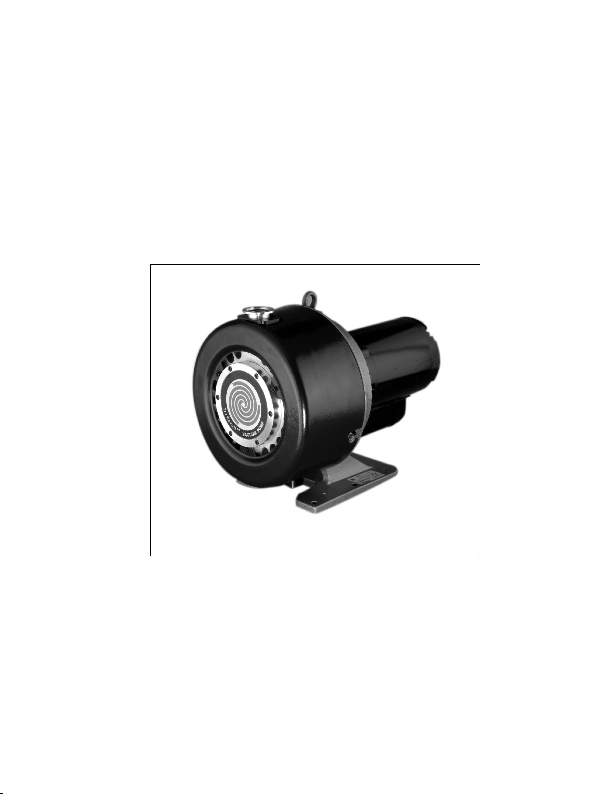
TriScroll
Dry Scroll
Vacuum Pump
TM
600 Series
INSTALLATION AND
OPERATION MANUAL
INSTALLATIONS- UND
BETRIEBSHANDBUCH
MANUEL D'INSTALLATION
ET D'OPÉRATION
MANUAL DE INSTALACIÓN Y
FUNCIONAMIENTO
MANUALE
D'INSTALLAZIONE E D'USO
取付と操作仕様書
安装和操作手册
설치 및 조작안내서
DRAFT 6/13/11
Manual No. 699904290
Revision M
March 2010
Page 2
TriScroll™ 600 Series
Dry Scroll Vacuum Pump
DRAFT 6/13/11
TriScroll is a trademark of Agilent, Inc.
Copyright 2010
Agilent Inc.
Page 3

TriScroll 600 Series Vacuum Pump
Table of Contents
Declaration of Conformity
Warranty ...................................................................viii
Warranty Replacement and Adjustment..............viii
Instructions for Use ..................................................... 1
General Information ................................................. 1
Storage ................................................................. 1
Unpacking and Inspection........................................ 1
Installation Requirements ......................................... 2
Safety ................................................................... 2
Operation................................................................. 4
Startup Procedure ................................................. 4
Shutdown Procedure ............................................ 4
Maintenance ............................................................ 4
Anleitungen zur Benutzung ........................................ 5
Allgemeine Informationen ........................................ 5
Lagerung .............................................................. 5
Auspacken und Inspektion ....................................... 5
Installationsanforderungen ....................................... 6
Sicherheit ............................................................. 6
Betrieb ..................................................................... 8
Startverfahren ....................................................... 8
Abschaltverfahren................................................. 8
Wartung ................................................................... 8
Instructions d'utilisation .............................................. 9
Informations générales ............................................. 9
Stockage............................................................... 9
Déballage et Inspection .......................................... 10
Exigences d'installation .......................................... 10
Sécurité .............................................................. 10
Opération............................................................... 12
Procédure de démarrage..................................... 12
Procédure d'arrêt................................................ 12
Entretien................................................................. 12
Instrucciones de uso .................................................. 13
Información general ............................................... 13
Almacenaje ........................................................ 13
Desembalaje e inspección...................................... 13
Requisitos de instalación ........................................ 14
Seguridad ........................................................... 14
Funcionamiento ..................................................... 16
Procedimiento de arranque ................................ 16
Procedimiento de parada.................................... 16
Mantenimiento....................................................... 16
Istruzioni per l'uso......................................................17
Informazioni generali ..............................................17
Conservazione ....................................................17
Disimballaggio ed ispezione ...................................17
Requisiti per l'installazione .....................................18
Sicurezza ............................................................18
Funzionamento .......................................................20
Procedura per l'avviamento.................................20
Procedura per lo spegnimento .............................20
Manutenzione.........................................................20
使用仕様
使用仕様 .....................................
使用仕様 使用仕様
概況概要 .................................. 21
開梱と点検 ................................ 21
取付要求 .................................. 22
操作 ...................................... 24
保守 ...................................... 24
使用说明 ...........................................................................25
一般信息 .......................................................................25
开箱和检查 ...................................................................25
安装要求 .......................................................................26
操作 ...............................................................................28
维护 ...............................................................................28
사용설명
사용설명 . . . . . . . . . . . . . . . . . . . . . . . . . . . . . . . . . . . . . .29
사용설명사용설명
일반정보 . . . . . . . . . . . . . . . . . . . . . . . . . . . . . . . . . . . .29
포장 열기 및 검사 . . . . . . . . . . . . . . . . . . . . . . . . . . . .29
설치요구 . . . . . . . . . . . . . . . . . . . . . . . . . . . . . . . . . . . .30
조작 . . . . . . . . . . . . . . . . . . . . . . . . . . . . . . . . . . . . . . . .32
유지 . . . . . . . . . . . . . . . . . . . . . . . . . . . . . . . . . . . . . . . .32
..................................... 21
..........................................................................
保存 .................................... 21
安全 .................................... 22
スタートアップ手順 ...................... 24
シャットダウン手順 ...................... 24
存放 ........................................................................... 25
安全 ........................................................................... 26
启动过程 ................................................................... 28
关机过程 ................................................................... 28
보관 . . . . . . . . . . . . . . . . . . . . . . . . . . . . . . . . . . . . . 29
안전장치 . . . . . . . . . . . . . . . . . . . . . . . . . . . . . . . . . 30
시동과정 . . . . . . . . . . . . . . . . . . . . . . . . . . . . . . . . . 32
중단과정 . . . . . . . . . . . . . . . . . . . . . . . . . . . . . . . . . 32
21
2121
iii
Page 4

TriScroll 600 Series Vacuum Pump
Technical Information ............................................... 33
Electrical Connections............................................ 36
Single Phase Motor Connection.......................... 36
Three Phase Motor Connection .......................... 37
Mechanical Connections ........................................ 38
Pump Location ................................................... 38
Rotation of the Pump Inlet
with Respect to the Motor Frame........................ 38
Pump Inlet.......................................................... 38
Pump Exhaust..................................................... 38
Optional Isolation Valve......................................... 38
Gas Ballast ............................................................. 39
Bearing Purge......................................................... 39
Purge Kit ................................................................ 39
Troubleshooting ..................................................... 40
Maintenance .......................................................... 41
General Information ........................................... 41
Related TriScroll Manuals................................... 41
Maintenance and Tooling Kits ............................ 41
Factory Service Options...................................... 42
Accessories......................................................... 42
Contacting Agilent.............................................. 42
Request for Return Health and Safety Certification
iv
Page 5

TriScroll 600 Series Vacuum Pump
List of Figures
Figure Caption Page
1 Interface Drawing with Dimensions . . . . . . 34
2 Pumping Speed Curves . . . . . . . . . . . . . . . . 34
3 TriScroll 600 Series Vacuum Pump
(Single Phase Pump Shown) . . . . . . . . . . . . . 35
4 Single Phase Motor Electrical Connections . 36
5 Three Phase Motor Electrical Connections . 37
6 Isolation Valve Location. . . . . . . . . . . . . . . . 38
List of Tables
Table Title Page
1 Pump Models and Power Cords..................... 3
2 Circuit Breaker Requirements......................... 3
3 Pumpenmodelle und Versorgungskabel ......... 7
4 Anforderungen an Stromunterbrecher ............ 7
5 Modèles de pompes et câbles ...................... 11
6 Exigences des coupe-circuits ....................... 11
7 Modelos de bomba y cables de corriente..... 15
8 Requisitos del disyuntor ............................... 15
9 Modelli di pompe e cavi di alimentazione... 19
10 Requisiti dell'interruttore automatico ........... 19
11 ポンプ型式と電源コード ...........................23
12 遮断器の要求 .............................................23
13 泵型号和电源电缆 ....................................... 27
14 断路器要求 .................................................. 27
15
펌프모델 및 코드
16
브레이커 요구
17 Specifications .............................................. 33
18 Full Load Motor Currents, Amperes.............. 36
19 VPI Valve Installation Data .......................... 39
20 Troubleshooting Chart ................................. 40
21 Other Related Manuals ................................ 41
22 Maintenance and Tooling Kits ..................... 41
23 Factory Service Options ............................... 42
24 Accessories.................................................. 42
. . . . . . . . . . . . . . . . . . . . . .31
. . . . . . . . . . . . . . . . . . . . . . . .31
v
Page 6

TriScroll 600 Series Vacuum Pump
This page intentionally left blank.
Page 7
Declaration of Conformity
Declaration of Conformity
Konformitätserklärung
Déclaration de Conformité
Declaración de Conformidad
Verklaring de Overeenstemming
Dichiarazione di Conformità
We
Wir
Nous
Nosotros
Wij
Noi
declare under our sole responsibility that the product,
erklären, in alleniniger Verantwortung, daß dieses Produkt,
déclarons sous notre seule responsabilité que le produit,
declaramos, bajo nuestra sola responsabilidad, que el producto,
verklaren onder onze verantwoordelijkheid, dat het product,
dichiariamo sotto nostra unica responsabilità, che il prodotto,
to which this declaration relates is in conformity with the following standard(s) or other normative documents.
auf das sich diese Erklärung bezieht, mit der/den flogenden Norm(en) oder Richtlinie(n) übereinstimmt.
auquel se réfère cette déclaration est conforme à la (auz) norme(s) ou au(x) document(s) normatif(s).
al que se refiere esta declaración es conforme a la(s) norma(s) u otro(s) documento(s) normativo(s).
waamaar deze verklaring verwijst, aan de volende norm(en) of richtlijn(en) beantwoodt.
a cui se rifersce questa dichiarazione è conforme alla/e sequente/I norma/o documento/I normativo/i.
Agilent, Inc.
Vacuum Products Division
121 Hartwell Avenue
Lexington, MA, 02421-3133 USA
TriScroll Series Vacuum Pump
Machinery Directive 2006/42/EC, Machinery Directive
EN 1012-2:1996 Compressors and Vacuum pumps Safety Reqmts; Part 2 Vacuum Pumps
EN 1050:1996 Safety of machinery - principles for risk assessment
EN 60204-1 Electrical equipment of industrial machines; general requirements
73/023/EEC, Low Voltage Directive
EN 60034 part 1 Rotating electrical devices - Part 1: Rating and performance
EN 61010-1:2001 Safety requirement for electrical equipment for measurement, control and
laboratory use
89/336/EEC, Electromagnetic Compatibility Directive
EN 61326-1:2006 Electrical equipment for measurement, control and laboratory use
(Inherently benign)
John Ehmann
Operations Manager
Vacuum Products Division
Agilent, Inc.
Lexington, Massachusetts, USA
March 2010
Page 8

Warranty
TriScroll 600 Series Vacuum Pump
Products manufactured by Seller are warranted against
defects in materials and workmanship for twelve (12)
months from date of shipment thereof to Customer, and
Seller’s liability under valid warranty claims is limited, at
the option of Seller, to repair, to replace, or refund of an
equitable portion of the purchase price of the Product.
Items expendable in normal use are not covered by this
warranty. All warranty replacement or repair of parts shall
be limited to equipment malfunctions which, in the sole
opinion of Seller, are due or traceable to defects in
original materials or workmanship. All obligations of
Seller under this warranty shall cease in the event of
abuse, accident, alteration, misuse, or neglect of the
equipment. In-warranty repaired or replaced parts are
warranted only for the remaining unexpired portion of the
original warranty period applicable to the repaired or
replaced parts. After expiration of the applicable warranty
period, Customer shall be charged at the then current
prices for parts, labor, and transportation.
Reasonable care must be used to avoid hazards. Seller
expressly disclaims responsibility for loss or damage
caused by use of its Products other than in accordance
with proper operating procedures.
Except as stated herein, Seller makes no warranty, express
or implied (either in fact or by operation of law), statutory
or otherwise; and, except as stated herein, Seller shall
have no liability under any warranty, express or implied
(either in fact or by operation of law), statutory or
otherwise. Statements made by any person, including
representatives of Seller, which are inconsistent or in
conflict with the terms of this warranty shall not be
binding upon Seller unless reduced to writing and
approved by an officer of Seller.
Warranty Replacement and Adjustment
All claims under warranty must be made promptly after
occurrence of circumstances giving rise thereto, and must
be received within the applicable warranty period by
Seller or its authorized representative. Such claims should
include the Product serial number, the date of shipment,
and a full description of the circumstances giving rise to
the claim. Before any Products are returned for repair
and/or adjustment, written authorization from Seller or its
authorized representative for the return and instructions
as to how and where these Products should be returned
must be obtained. Any Product returned to Seller for
examination shall be prepaid via the means of
transportation indicated as acceptable by Seller. Seller
reserves the right to reject any warranty claim not
promptly reported and any warranty claim on any item
that has been altered or has been returned by
non-acceptable means of transportation. When any
Product is returned for examination and inspection, or for
any other reason, Customer shall be responsible for all
damage resulting from improper packing or handling, and
for loss in transit, notwithstanding any defect or
non-conformity in the Product. In all cases, Seller has the
sole responsibility for determining the cause and nature of
failure, and Seller’s determination with regard thereto
shall be final.
If it is found that Seller’s Product has been returned
without cause and is still serviceable, Customer will be
notified and the Product returned at its expense; in
addition, a charge for testing and examination may be
made on Products so returned.
3/1/00
viii
Page 9
TriScroll 600 Series Vacuum Pump
Instructions for Use
General Information
This equipment is designed for use by professionals. The
user should read this instruction manual and any other
additional information supplied by Agilent before
operating the equipment. Agilent will not be held
responsible for any events that occur due to
non-compliance with these instructions, improper use by
untrained persons, non-authorized interference with the
equipment, or any action contrary to that provided for by
specific national standards.
The TriScroll™ 600 is a dry scroll vacuum pump. This
pump is suitable for pumping air or inert gases. The pump
is not intended to pump toxic, corrosive, explosive, or
particulate-forming gases.
The following paragraphs contain all the information
necessary to guarantee the safety of the operator when
using the equipment. Detailed information is supplied in
“Technical Information” on page 33.
This manual uses the following standard safety protocol:
WARNING The warning messages are for
attracting the attention of the operator to a particular procedure or practice which, if not followed correctly,
could lead to serious injury.
CAUTION The caution messages are displayed
before procedures, which if not followed, could cause damage to the
equipment.
Unpacking and Inspection
The shipping container is a double carton.
1. After opening the outer box, remove the foam packing.
2. Slit open the inner box.
3. Lift the pump with the plywood base out of the inner
box.
4. Remove the four bolts securing the pump frame to
the plywood base.
5. Locate the NW25 exhaust fitting and set it aside.
6. Inspect the pump for damage.
If there is shipping damage, contact the freight carrier
and your local Agilent sales office immediately.
7. Save the carton and packing materials.
Total weight of the package, including the pump, is
approximately 40 kg (87 lbs).
WARNING When unpacking the pump, be sure
not to drop it, and avoid any kind of
sudden impact or shock vibration
to it.
WARNING The TriScroll 600 weighs 32 kg
(70 lbs). To avoid injury, use proper
lifting techniques when moving the
pump.
DRAFT 6/13/11
NOTE The notes contain important
information taken from the text.
Storage
When transporting and storing the pump, the following
environmental requirements should not be exceeded:
Temperature: –20 °C to 60 °C (–4 °F to 140 °F)
Relative humidity: 0 to 95% (non-condensing)
NOTE Normal exposure to the environ-
ment cannot damage the pump.
Nevertheless, it is advisable to keep
the pump inlet closed until the
pump is installed in the system.
1
Page 10

TriScroll 600 Series Vacuum Pump
Installation Requirements
Safety
Do not remove or modify any safety or insulating
equipment from the pump. To do so may create a serious
safety hazard and may void the warranty.
WARNING
CAUTION Although the pump can pump trace
❑
This pump is designed to pump
air and inert gases only; it is not
designed to pump explosive, flammable, toxic, or corrosive gases.
They can cause bodily injury,
explosion, or fire.
❑
Install in an area that is not
exposed to rain, steam, or excessive
humidity. They can cause electric
shock, short circuits, and severe
bodily injury.
❑
Before inspecting or servicing the
pump, be sure the electrical supply
is disconnected.
❑
Consult a qualified electrician
whenever wiring the pump.
particulates normally found in the
atmosphere, it is not designed for
process solids, chemicals, powders,
solvents, condensates, or other particulates. They can damage the
equipment, degrade its performance,
or shorten its useful life.
During operation, the following environmental
conditions should not be exceeded:
Temperature: +5 °C to +40 °C (41 °F to 104 °F)
Relative humidity: 0 to 95% (non-condensing)
CAUTION Do not block the fan ducts because the
pump can become overheated. A pump
surface temperature in excess of 55 °C
(131 ° F) is potentially damaging. If such
conditions are observed, turn pump off
and allow to cool. Disassemble, inspect
for damage, and repair if necessary.
CAUTION As supplied from the factory, the pump
is configured as shown in the following
table. Verify that the configuration
matches the supply voltage.
If voltage changeover is required,
configure the voltage as described in
“Electrical Connections” on page 36
and page 37.
DRAFT 6/13/11
Single and three phase pumps operate in a clockwise direction when
viewed from the motor end. (Note
the arrow on the pump frame.)
Improper rotation can cause permanent damage to the pump.
2
Page 11
TriScroll 600 Series Vacuum Pump
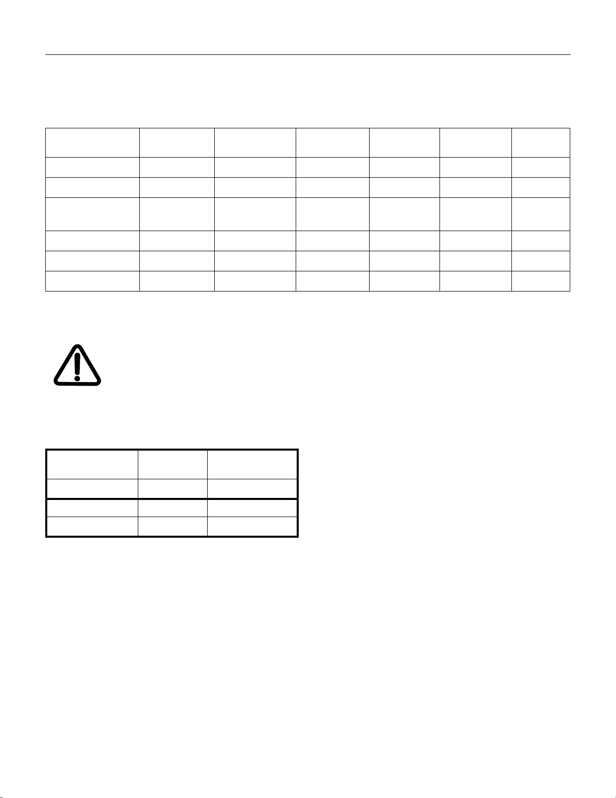
Table 1 lists the available TS-600 pump models and
indicates the power cord to be used with each particular
pump.
Table 1 Pump Models and Power Cords
Pump Model Motor Voltage Plug Type Fusing Conductor
PTS06001UNIV 100-115 VAC NEMA 5-15P - 14 Gage UL/CSA 2.5 m
PTS06001UNIVEU 200-230 VAC CEE 7/7 - 3x1.50 mm
PTS06001UNIVUK 200-230 VAC BS 1363 BS 1362
PTS06003UNIV 200-230 VAC - - - - -
PTS06101UNIV 100-115 VAC NEMA 5-15P - 14 Gage UL/CSA 2.5m
PTS06001UVPI 100-115 VAC NEMA 5-15P - 14 Gage UL/CSA 2.5m
Circuit Breakers
WARNING Protect against short circuits by
installing a circuit breaker of the
proper capacity.
Three phase pumps are shipped without a power cord.
A three phase power cable kit, Agilent part number
S4789001, is available. This kit does not include a plug.
Cord Marking Cord
Size
2
<HAR> 2.5 m
3x1.50 mm
13 Amp
2
<HAR> 2.5 m
Length
Table 2 lists the circuit breaker capacity required for pump
motors of various voltages, single and three-phase.
Table 2 Circuit Breaker Requirements
Single Phase Motor 100-115 VAC
50/60 Hz
Breaker capacity 20 Amperes 10 Amperes
Three Phase Motor 200-230 VAC 380-415-460 VAC
Breaker capacity 10 Amperes 5 Amperes
200-230 VAC
50/60 Hz
DRAFT 6/13/11
3
Page 12
TriScroll 600 Series Vacuum Pump
Operation
In order to reach ultimate vacuum, the pump must be left
running for about one hour with the inlet sealed.
Unlike conventional oil-sealed pumps, Agilent’s dry scroll
pumps do not have fluid to cleanse them of accumulated
dust and debris. Run the pump periodically at atmosphere
for a minute or two to flush out the pump. Flush the pump
regularly and adjust this schedule according to your
specific conditions.
WARNING During operation the outer surface
of the motor housing can become
hot. Avoid touching the motor housing during pump operation.
Startup Procedure
1. Be sure that the vacuum system isolation valve is
closed.
2. Turn on power to the pump.
3. Open the isolation valve.
Shutdown Procedure
1. Close the vacuum system isolation valve. This
prevents debris in pump from being transported into
the vacuum system.
2. Turn off power to the pump.
Maintenance
Personnel responsible for pump operation and
maintenance must be well-trained and aware of the
accident prevention rules.
WARNING
NOTE Before returning the pump to the
If a pump is to be discarded, it must be disposed of in
accordance with specific national and local standards.
❑
Death may result from contact
with high voltages. Always take
extreme care and observe the accident prevention regulations in force.
❑
When the machine is powered
up, be careful of moving parts and
high voltages.
❑
If you have to perform maintenance on the pump after a considerable time in operation, allow the
pump to cool as the temperature of
the outer surface may be in excess of
55 °C (131 °F).
❑
Always disconnect your power
supply to the pump before beginning
maintenance work.
factory for repair, the “Health and
Safety” sheet attached to this instruction manual must be completed and
sent to the local sales office. A copy
of the sheet must be inserted in the
pump package before shipping.
DRAFT 6/13/11
4
Page 13
TriScroll 600 Series Vacuum Pump
Anleitungen zur Benutzung
Allgemeine Informationen
Dieses Gerät ist zur Benutzung durch Fachkräfte
bestimmt. Der Benutzer muss vor der Bedienung des
Gerätes das Anleitungshandbuch und alle zusätzlichen
von Agilent zur Verfügung gestellten Informationen
gelesen haben. Agilent kann nicht für Vorfälle
verantwortlich gemacht werden, die aus der
Nichtbeachtung dieser Anleitungen, aus der inkorrekten
Verwendung des Gerätes durch ungeschulte Personen
und aus dem unbefugten Umgang mit dem Gerät oder
anderen den zutreffenden gültigen Normen
zuwiderlaufenden Handlungen resultieren.
Die TriScroll™ 600 ist eine trockene
Scroll-Vakuumpumpe. Diese Pumpe eignet sich zum
Pumpen von Luft oder inerten Gasen. Die Pumpe ist nicht
zum Pumpen von toxischen, korrosiven, explosiven oder
partikelbildenden Gasen vorgesehen.
Die folgenden Abschnitte enthalten alle erforderlichen
Informationen, um die Sicherheit des Bedieners bei der
Benutzung des Gerätes zu gewährleisten. Ausführliche
Informationen befinden sich auf Seite 25 im Abschnitt
"Technische Informationen".
Dieses Handbuch verwendet das folgende
Standard-Sicherheitsprotokoll:
WARNUNG Die Warnungsmeldungen dienen
dazu, die Aufmerksamkeit des Bedieners auf ein bestimmtes Verfahren
oder eine Methode zu lenken, deren
inkorrekte Befolgung zu schweren
Verletzungen führen kann.
Auspacken und Inspektion
Beim Versandbehälter handelt es sich um einen
doppelten Karton.
1. Entfernen Sie nach dem Öffnen des äußeren Kartons
die Schaumverpackung.
2. Schneiden Sie den inneren Karton auf.
3. Heben Sie die Pumpe mit der Sperrholzunterlage aus
dem inneren Karton heraus.
4. Entfernen Sie die vier Schrauben, mit denen der
Pumpenrahmen an der Sperrholzunterlage befestigt
ist.
5. Machen Sie das NW25 Auslass-Montageteil ausfindig
und legen Sie es beiseite.
6. Prüfen Sie, ob die Pumpe beim Transport beschädigt
worden ist.
Wenn Transportschäden vorhanden sein sollten,
setzen Sie sich sofort mit dem Transportunternehmen
und Ihrem lokalen Agilent Verkaufsbüro in
Verbindung.
7. Bewahren Sie den Karton und das
Verpackungmaterial auf.
Das Gesamtgewicht der Sendung, einschließlich der
Pumpe, beträgt ungefähr 40 kg (87 lbs).
WARNUNG Gehen Sie beim Auspacken der
Pumpe vorsichtig vor, um das Gerät
nicht fallen zu lassen, und vermeiden Sie jede Art von plötzlichen
Stößen oder Erschütterungen.
FT 6/13/11
DRA
VORSICHT Die Vorsichtsmeldungen werden vor
HINWEIS Die Hinweise enthalten wichtige
Verfahren angezeigt, deren Nichtbeachtung zur Beschädigung des
Gerätes führen kann.
Informationen, die dem Text entnommen wurden.
Lagerung
Beim Transport und bei der Lagerung der Pumpe dürfen
die folgenden Umgebungsbedingungen nicht
überschritten werden:
Temperatur:
Relative
Feuchtigkeit: 0 bis 95 % (nicht kondensierend)
−
20 °C bis 60 °C (− 4 °F bis 140 °F)
WARNUNG Die TriScroll 600 wiegt 32 kg (70
lbs). Benutzen Sie beim Heben und
beim Transport der Pumpe geeignete
Hebetechniken, um Verletzungen zu
vermeiden.
HINWEIS Normale Umgebungseinflüsse kön-
nen die Pumpe nicht beschädigen.
Trotzdem wird empfohlen, den
Pumpeneinlass verschlossen zu
halten, bis die Pumpe im System
installiert wird.
5
Page 14

TriScroll 600 Series Vacuum Pump
Installationsanforderungen
Sicherheit
Sicherheits- oder Isoliervorrichtungen dürfen nicht von
der Pumpe entfernt oder modifiziert werden, da sonst
schwerwiegende Sicherheitsrisiken entstehen und die
Garantie ihre Gültigkeit verlieren kann.
WARNUNG
❑
Diese Pumpe ist ausschließlich
zum Pumpen von Luft und inerten
Gasen zu verwenden. Sie ist nicht
zum Pumpen von explosiven, brennbaren, toxischen oder korrosiven
Gasen vorgesehen. Diese können
Verletzungen, Explosionen oder
Feuer verursachen.
❑
Installieren Sie die Pumpe in
einem Bereich, der keinem Regen,
Dampf oder übermäßiger
Feuchtigkeit ausgesetzt ist. Diese
Umgebungsbedingungen können
elektrische Schocks, Kurzschlüsse
und schwere Verletzungen verursachen.
❑
Stellen Sie vor der Inspektion oder
Wartung der Pumpe sicher, dass die
Stromversorgung abgetrennt ist.
❑
Konsultieren Sie zum Verdrahten
der Pumpe einen qualifizierten Elektriker.
Während des Betriebes dürfen die folgenden
Umgebungsbedingungen nicht überschritten werden:
Temperatur: + 5 °C bis + 40 °C (41 °F bis 104 °F)
Relative
Feuchtigkeit: 0 bis 95 % (nicht kondensierend)
VORSICHT Blockieren Sie nicht die Lüfter-Aus-
trittskanäle, da sich die Pumpe sonst
überhitzt. Eine Oberflächentemperatur der Pumpe von über 55 °C
(131 ° F) kann die Pumpe beschädigen. Wenn derartige Bedingungen
beobachtet werden, schalten Sie die
Pumpe ab und lassen Sie sie
abkühlen. Nehmen Sie die Pumpe
auseinander, überprüfen Sie, ob
Schäden vorhanden sind und reparieren Sie diese gegebenenfalls.
VORSICHT Die Konfiguration der Pumpe bei der
Lieferung vom Werk ist in der folgenden Tabelle zu sehen. Überprüfen Sie, dass die Konfiguration
der Versorgungsspannung entspricht.
Wenn eine Spannungsumstellung
erforderlich ist, konfigurieren Sie die
Spannung wie im Abschnitt "Elektrische Anschlüsse" auf Seite 28 und
Seite 29 beschrieben.
VORSICHT Obwohl die Pumpe Spurenpartikel
pumpen kann, die normalerweise in
der Atmosphäre zu finden sind, ist
DRAFT 6/13/11
sie nicht für Feststoffe, Chemikalien,
Pulver, Lösungsmittel, Kondensate
oder andere Partikel vorgesehen.
Diese können das Gerät beschädigen, seine Leistung herabsetzen oder
seine Lebensdauer verkürzen.
Ein- und Dreiphasenpumpen operieren in Uhrzeigerrichung, wenn Sie
von der Motorseite aus betrachtet
werden. (Beachten Sie den Pfeil auf
dem Pumpenrahmen.) Eine inkorrekte Rotation kann zu permanenten
Schäden an der Pumpe führen..
6
Page 15
TriScroll 600 Series Vacuum Pump
In Tabelle 3 sind die lieferbaren TS-600 Pumpenmodelle
aufgeführt. Die Tabelle enthält außerdem Informationen
zu den Spannungsversorgungskabeln, die mit jeder
einzelnen Pumpe verwendet werden müssen.
Tabelle 3 Pumpenmodelle und Versorgungskabel
Pumpenmodell Motor-
spannung
PTS06001UNIV 100-115 VAC NEMA 5-15P - 14 Gage UL/CSA 2,5 m
PTS06001UNIVEU 200-230 VAC CEE 7/7 - 3x1,50 mm
PTS06001UNIVUK 200-230 VAC BS 1363 BS 1362
PTS06003UNIV 200-230 VAC - - - - -
PTS06101UNIV 100-115 VAC NEMA 5-15P - 14 Gage UL/CSA 2.5m
PTS06001UVPI 100-115 VAC NEMA 5-15P - 14 Gage UL/CSA 2.5m
Stromunterbrecher
WARNUNG Durch die Installation eines Unter-
brechers der richtigen Kapazität
werden Kurzschlüsse vermieden.
Steckerart Sicherung Leiter-
Dreiphasenpumpen werden ohne
Spannungsversorgungskabel geliefert. Ein
Dreiphasen-Kabelsatz, Agilent Teilenummer S4789001,
ist lieferbar. Dieser Satz enthält keinen Stecker.
Kabel-
größe
3x1,50 mm
13 Amp
markierung
2
<HAR> 2,5 m
2
<HAR> 2,5 m
Kabel-
länge
In Tabelle 4 ist die Kapazität der Stromunterbrecher
aufgeführt, die für Pumpenmotoren verschiedener
Spannungen für Ein- und Dreiphasemotoren erforderlich
sind.
Tabelle 4 Anforderungen an Stromunterbrecher
Einphasenmotor 100-115 VAC
50/60 Hz
Kapazität des
Unterbrechers
Dreiphasenmoto 200-230 VAC 380-415-460 VAC
Kapazität des
Unterbrechers
20 Ampere 10 Ampere
10 Ampere 5 Ampere
200-230 VAC
50/60 Hz
FT 6/13/11
DRA
7
Page 16

TriScroll 600 Series Vacuum Pump
Betrieb
Um ein optimales Vakuum zu erreichen, muss die Pumpe
für etwa eine Stunde mit abgedichtetem Einlass laufen.
Im Gegensatz zu herkömmlichen ölgekapselten Pumpen
haben die trockenen Scroll-Pumpen von Agilent keine
Flüssigkeit, um sie von angesammeltem Staub und
Ablagerungen zu reinigen. Lassen Sie die Pumpe
periodisch für ein bis zwei Minuten bei Atmosphäre
laufen, um sie auszuspülen. Spülen Sie die Pumpe
regelmäßig aus und passen Sie diesen Zeitplan Ihren
speziellen Bedingungen an.
WARNUNG Das Motorgehäuse kann im Betrieb
heiß werden. Das Motorgehäuse bei
laufender Pumpe nicht berühren.
Startverfahren
1. Stellen Sie sicher, dass das Isolationsventil des
Vakuumsystems geschlossen ist.
2. Schalten Sie die Stromversorgung für die Pumpe ein.
3. Öffnen Sie das Isolationsventil.
Wartung
Das für den Betrieb und die Wartung der Pumpe
zuständige Personal muss gut geschult und mit den
Regeln zur Unfallvermeidung vertraut sein.
WARNUNG
❑
o Der Kontakt mit hohen Spannungen kann zum Tod führen. Lassen Sie immer äußerste Vorsicht
walten und beachten Sie die gültigen Vorschriften zur Unfallvermeidung.
❑
o Wenn die Maschine angeschaltet ist, muss besonders auf
bewegliche Teile und hohe Spannungen geachtet werden.
❑
o Wenn Sie Wartungsarbeiten an
der Pumpe durchführen müssen,
nachdem diese für längere Zeit in
Betrieb war, lassen Sie die Pumpe
zuerst abkühlen, da die Temperatur
der Außenfläche der Maschine 55
°C (131 °F) überschreiten kann.
❑
o Trennen Sie immer die Stromversorgung zur Pumpe ab, bevor Sie
mit den Wartungsarbeiten beginnen.
Abschaltverfahren
1. Schließen Sie das Isolationsventil des
Vakuumsystems. Dadurch wird verhindert, dass
Ablagerungen aus der Pumpe in das Vakuumsystem
transportiert werden.
2. Schalten Sie die Stromversorgung zur Pumpe ab.
DRAFT 6/13/11
HINWEIS Bevor Sie die Pumpe zur Reparatur
an das Werk zurückschicken, muss
das Blatt "Gesundheit und Sicherheit", das diesem Handbuch
beigefügt ist, ausgefüllt und an das
lokale Verkaufsbüro geschickt werden. Eine Kopie des Blattes muss vor
dem Versand in die Verpackung der
Pumpe eingelegt werden.
Wenn eine Pumpe beseitigt werden soll, muss dies in
Übereinstimmung mit den speziellen nationalen und
lokalen Normen erfolgen.
8
Page 17

TriScroll 600 Series Vacuum Pump
Instructions d'utilisation
Informations générales
Cet équipement est conçu pour être utilisé par des
professionnels. L'utilisateur est tenu de lire ce manuel
d'instructions ainsi que toutes les informations
supplémentaires fournies par Agilent avant de faire
fonctionner l'équipement. Agilent ne sera pas tenu
responsable de tout incident se produisant en raison de la
non observation de ces instructions, d'une utilisation
incorrecte par un personnel non formé, d'une
interférence non autorisée avec l'équipement, ou de toute
action contraire à celles stipulées par les normes
nationales appropriées.
La TriScroll™ 600 est une pompe à vide sèche de type «
scroll ». Cette pompe peut être utilisée pour pomper de
l'air ou des gaz inertes. Elle n'est pas prévue pour pomper
des gaz toxiques, corrosifs, explosifs ou formant des
particulats.
Les paragraphes suivants contiennent toutes les
informations nécessaires pour garantir la sécurité de
l'opérateur dans l'utilisation de cet équipement. Des
informations détaillées sont fournies à la section «
Informations techniques » à la page 25.
Ce manuel utilise le protocole des normes de sécurité
suivant:
ADVERTISSEMENT Les messages d'avertissement visent
à attirer l'attention de l'opérateur
vis-à-vis d'une procédure ou pratique particulière, laquelle, si elle
n'est pas observée correctement,
pourrait entraîner des blessures
graves
ATTENTION Les messages d'attention sont
affichés avant des procédures,
lesquelles, si elles ne sont pas
respectées, pourraient causer des
dommages à l'équipement
REMARQUES Les remarques contiennent des infor-
mations importantes prélevées du
texte.
Stockage
Pendant le transport et le stockage de la pompe, les
exigences environnementales suivantes ne doivent pas
être dépassées :
FT 6/13/11
Température :
Humidité relative : 0 à 95% (non-condensée)
−
20 °C à 60 °C (−4 °F à 140 °F)
DRA
9
Page 18

TriScroll 600 Series Vacuum Pump
Déballage et Inspection
Le conteneur d'expédition est un carton double.
1. Après l'ouverture de la boîte extérieure, retirez le
bourrage de mousse.
2. Ouvrez la boîte intérieure à l'aide d'une lame.
3. Soulevez la pompe et la base de contreplaqué de la
boîte intérieure.
4. Retirez les quatre écrous fixant le châssis de la
pompe à la base de contreplaqué.
5. Repérez le raccord d'échappement NW25 et
mettez-le de côté.
6. Contrôlez que la pompe n'est pas endommagée.
Si la pompe a été endommagée durant le transport,
contactez le transporteur et votre bureau de vente
Agilent local immédiatement.
7. Conservez le carton et le garnissage.
Le poids total du paquet, pompe comprise, est de 40 kg
(87 livres) environ.
ADVERTISSEMENT Lorsque vous déballez la pompe,
faites attention à ne pas la laisser
tomber, et évitez tout impact soudain ou vibrations dues à des chocs.
ADVERTISSEMENT La TriScroll 600 pèse 32 kg
(70 livres). Pour éviter tout risque de
blessures, utilisez des techniques de
levage appropriées lorsque vous
déplacez la pompe.
DRAFT 6/13/11
REMARQUES Une exposition normale à l'environ-
nement n'endommagera pas la
pompe. Toutefois, il est conseillé de
tenir l'entrée de la pompe fermée
jusqu'à ce que la pompe soit
installée dans le système.
Exigences d'installation
Sécurité
Ne retirez pas ni ne modifiez l'équipement de sécurité ou
d'isolation de la pompe. Ceci pourrait représenter un
risque important d'incendie et pourra invalider la
garantie.
ADVERTISSEMENT
ATTENTION Bien que la pompe soit en mesure
❑
Cette pompe est conçue pour
pomper de l'air et des gaz inertes
uniquement ; elle n'est pas conçue
pour pomper des gaz explosifs,
inflammables, toxiques ou corrosifs.
Ceci pourrait représenter des risques
de blessures corporelles, d'explosion
ou d'incendie.
❑
Installez dans une zone qui ne
soit pas exposée à la pluie, à la
vapeur ou à une humidité excessive.
Ceci peut causer des chocs électriques, des courts-circuits ainsi que
des blessures corporelles importantes.
❑
Avant d'inspecter ou de réparer la
pompe, assurez-vous que l'alimentation électrique a été déconnectée.
❑
Consultez un électricien qualifié
lorsque vous effectuez le câblage de
la pompe.
de pomper des particulats traces se
trouvant normalement dans l'atmosphère, elle n'est pas conçue pour
traiter des solides, produits
chimiques, poudres, solvants, condensats ou autres particulats. Ces
éléments peuvent endommager
l'équipement, dégrader sa performance ou raccourcir sa durée de
vie.
Les pompes monophasées et
triphasées opèrent dans la direction
des aiguilles d'une montre lorsque
vues du côté moteur. (Notez la
flèche sur le cadre de la pompe.)
Une rotation incorrecte peut causer
des dégâts permanents à la pompe.
10
Page 19

TriScroll 600 Series Vacuum Pump
Pendant l'opération, les conditions environnementales
suivantes ne doivent pas être dépassées :
Température : +5 °C à +40 °C (41 °F à 104 °F)
Humidité relative : 0 à 95% (non condensée)
ATTENTION Ne bloquez pas les conduits de ven-
tilation car la pompe peut surchauffer. Une température à la
surface de la pompe supérieure à
55°C (131° F) est potentiellement
dangereuse. Si de telles conditions
sont observées, éteignez la pompe et
laissez-la refroidir. Désassemblez,
examinez les traces de dommages,
puis réparez, si nécessaire.
Le Table 5 liste les modèles de pompes TS-600
disponibles et indique le câble devant être utilisé avec
chaque pompe particulière.
Table 5 Modèles de pompes et câbles
Modèle Pompe Tension Moteur Type Fiche Fusibles Taille
ATTENTION Lorsqu'elle est fournie par l'usine, la
Les pompes triphasées sont expédiées sans câble
d'alimentation. Un jeu de câble d'alimentation triphasé,
Agilent pièce n° S4789001, est disponible. Ce jeu
n'inclut pas de prise.
pompe est configurée tel qu'indiqué
dans le tableau suivant. Vérifiez que
la configuration correspond à la tension d'alimentation.
Si un changement de tension est requis, configurez la tension tel que
décrit dans « Connexions électriques
» à la page 28 et page 29.
Conducteur
Marquage
Câble
Longueur
Câble
PTS06001UNIV 100-115 VAC NEMA 5-15P - 14 Gage UL/CSA 2,5 m
PTS06001UNIVEU 200-230 VAC CEE 7/7 - 3x1,50 mm
PTS06001UNIVUK 200-230 VAC BS 1363 BS 1362
13 Amp
PTS06003UNIV 200-230 VAC - - - - -
PTS06101UNIV 100-115 VAC NEMA 5-15P - 14 Gage UL/CSA 2.5m
PTS06001UVPI 100-115 VAC NEMA 5-15P - 14 Gage UL/CSA 2.5m
Coupe-circuits Table 6 indique la capacité des coupe-circuits requis pour
les moteurs des pompes de différentes tensions,
ADVERTISSEMENT Protégez-vous contre les courts-cir-
cuits en installant un coupe-circuit
de la capacité adéquate.
monophasés et triphasés.
monophasé
Capacité du
coupe-circuit
Moteur triphasé 200-230 VAC 380-415-460 VAC
Capacité du
coupe-circuit
3x1,50 mm
Table 6 Exigences des coupe-circuits
Moteur
2
<HAR> 2,5 m
2
<HAR> 2,5 m
100-115 VAC
50/60 Hz
20 Ampères 10 Ampères
10 Ampères 5 Ampères
200-230 VAC
50/60 Hz
FT 6/13/11
DRA
11
Page 20

TriScroll 600 Series Vacuum Pump
Opération
Afin d'atteindre le vide complet, la pompe doit
fonctionner pendant environ une heure avec l'entrée
hermétiquement fermée.
À la différence des pompes à huile conventionnelles, les
pompes sèches de type « scroll » Agilent n'ont pas de
fluides pour les débarrasser de la poussière et des débris
accumulés. Faites fonctionner la pompe régulièrement à
l'atmosphère pendant une minute ou deux pour vider la
pompe. Nettoyez-la ainsi régulièrement et ajuster ce
programme en fonction de vos conditions particulières.
ADVERTISSEMENT Au cours du fonctionnement, la sur-
face externe du compartiment moteur
peut devenir très chaude. Evitez de
toucher le compartiment moteur lorsque la pompe fonctionne.
Procédure de démarrage
1. Assurez-vous que la soupape d'isolation du système
de vide est fermée.
2. Connectez la pompe à l'alimentation.
3. Ouvrez la soupape d'isolation.
Procédure d'arrêt
1. Fermez la soupape d'isolation du système de vide.
Ceci empêche aux débris dans la pompe d'entrer
dans le système de vide.
2. Déconnectez la pompe de l'alimentation.
DRAFT 6/13/11
Entretien
Le personnel responsable de l'opération et de l'entretien
de la pompe doit être parfaitement formé et conscient des
règles de prévention des accidents.
ADVERTISSEMENT
REMARQUES Avant de renvoyer la pompe à
Si une pompe doit être jetée, elle devra être détruite
conformément aux normes nationales et locales
appropriées.
❑
Un contact avec des tensions
élevées représente un danger de
mort. Faites toujours très attention et
observez les réglementations en
vigueur sur la prévention des accidents.
❑
Lorsque la machine est alimentée,
faites très attention aux pièces
mobiles ainsi qu'aux tensions
élevées.
❑
Si vous devez réaliser un travail
d'entretien sur la pompe après une
longue période d'opération, laissez
la pompe refroidir car la température
de la surface extérieure peut être
supérieure à 55 °C (131 °F).
❑
Déconnectez toujours votre alimentation de la pompe avant de
commencer tout travail d'entretien.
l'usine pour la faire réparer, la fiche
de « Santé et Sécurité » attachée à ce
manuel
d'instruction doit être remplie et renvoyée au bureau de vente local. Une
copie de la fiche doit être jointe au
colis avant
l'expédition.
12
Page 21

TriScroll 600 Series Vacuum Pump
Instrucciones de uso
Información general
Este equipos está diseñado para que lo utilicen
profesionales. El usuario debería leer este manual de
instrucciones y cualquier otra información adicional
suministrada por Agilent antes de trabajar con el equipo.
Agilent no se hará responsable de cualquier evento que
pueda ocurrir debido al no cumplimiento con estas
instrucciones, el uso inapropiado por personas no
cualificadas, la interferencia no autorizada en el equipo,
o cualquier otra acción contraria a lo establecido en las
normativas nacionales específicas.
La TriScroll™ 600 es una bomba de vacío de sección
descendente en seco. Esta bomba está preparada para el
bombeo de aire o gases inertes. La bomba no está
preparada para el bombeo de gases tóxicos, corrosivos,
explosivos o que formen macropartículas.
Los siguientes párrafos contienen toda la información
necesaria para garantizar la seguridad del operador
mientras utilice el equipo. Si desea información más
detallada, consulte la sección "Información técnica" en la
página 25.
Este manual utiliza el siguiente protocolo estándar de
seguridad:
ADVERTENCIA Los mensajes de advertencia pre-
tenden atraer la atención del operador sobre un procedimiento o
práctica concreto, el cual, en caso
de no seguirlo correctamente puede
dar lugar a lesiones graves.
PRECAUCIÓN Los mensajes de precaución se
muestran ante de procedimientos,
que en caso de no seguirse podrían
provocar daños a los equipos.
NOTA Las notas contienen información
importante tomada del texto.
Desembalaje e inspección
El embalaje de transporte es un cartón doble.
1. Tras abrir la caja exterior, retire la espuma protectora.
2. Abra la caja interior.
3. Saque la bomba con la base de madera
contrachapada de la caja interior.
4. Retire los cuatro pernos que sujetan el bastidor de la
bomba a la base de madera contrachapada.
5. Localice el racor de escape NW25 y déjelo a un
lado.
6. Inspeccione cualquier posible daño de la bomba.
Si hubiera algún daño producido en el transporte,
póngase de inmediato en contacto con la empresa de
transporte o las oficinas de ventas Agilent.
7. Guarde el cartón y los materiales de embalaje.
El peso total del embalaje, incluyendo la bomba es de
aproximadamente 40 kg (87 libras).
ADVERTENCIA Al desembalar la bomba, asegúrese
de no dejarla caer y evite cualquier
tipo de impacto brusco o vibración
que pueda afectarla.
ADVERTENCIA La bomba TriScroll 600 pesa 32 kg
(70 libras). Para evitar lesiones,
utilice las técnicas de izado adecuadas cuando transporte la bomba.
NOTA La exposición normal a entorno no
dañará la bomba. Sin embargo, es
aconsejable mantener la admisión
de la bomba cerrada, hasta que ésta
se instale en el sistema.
FT 6/13/11
DRA
Almacenaje
Cuando se transporte o almacene la bomba, no deberán
superarse las siguientes condiciones ambientales:
Temperatura:
Humedad relativa: 0 a 95% (sin condensación)
−
20 °C a 60 °C (−4 °F a 140 °F)
13
Page 22

TriScroll 600 Series Vacuum Pump
Requisitos de instalación
Seguridad
No desmonte ni modifique ninguno de los equipos de
seguridad o aislamiento presentes en la bomba. Si lo
hiciera puede crear un grave riesgo de seguridad,
pudiendo invalidar la garantía.
ADVERTENCIA
❑
Esta bomba está diseñada para
bombear únicamente aire y gases
inertes, no para bombear gases
explosivos, tóxicos, inflamables o
corrosivos. Estos últimos pueden
provocar lesiones corporales, explosiones o incendios.
❑
Instale la bomba en una zona no
expuesta a la lluvia, el vapor o a una
humedad excesiva. Pueden provocar sacudidas eléctricas, cortocircuitos y graves lesiones.
❑
Antes de inspeccionar o realizar
operaciones de mantenimiento en la
bomba, asegúrese de que el suministro eléctrico está desconectado.
❑
Consulte con un electricista cualificado siempre que deba cablear la
bomba.
Durante su funcionamiento, las siguientes condiciones
ambientales no deben superarse:
Temperatura: +5 °C a +40 °C (41 °F a 104 °F)
Humedad relativa: 0 a 95% (sin condensación)
PRECAUCIÓN No bloquee los conductos del venti-
lador ya que la bomba se sobrecalentaría. Una temperatura en la
superficie de la bomba de más de
55ºC (131 ºF) es potencialmente perjudicial para la propia bomba. Si se
observan dichas condiciones,
desconecte la bomba y deje que se
enfríe. Desmonte la bomba, inspecciónela en busca de posibles daños
y repárela si fuera necesario.
PRECAUCIÓN Tal como se suministra de fábrica, la
bomba está configurada según la
siguiente tabla. Verifique que la configuración se ajusta al voltaje de
suministro.
Si se requiere un cambio de voltaje,
configure el voltaje según se
describe en el apartado "Conexiones
eléctricas" de la página 28 y 29.
PRECAUCIÓN Aunque la bomba puede bombear
micropartículas normalmente presentes en la atmósfera, no está diseñada para el proceso de sólidos,
productos químicos, polvos, disolventes, condensados u otras macro-
DRAFT 6/13/11
partículas. Pueden dañar el equipo,
degradar su rendimiento o acortar su
vida útil..
Las bombas monofásicas y trifásicas
funcionan en la dirección de las
agujas del reloj vistas desde el
extremo del motor. (Fíjese en la
flecha situada en el bastidor de la
propia bomba). Un giro inapropiado
puede dañar de forma permanente
la bomba..
14
Page 23

TriScroll 600 Series Vacuum Pump
La Tabla 7 enumera los modelos de bombas TS-600
disponibles e indica el cable de corriente que debe
utilizarse con cada bomba en concreto.
Tabla 7 Modelos de bomba y cables de corriente
Modelo de bomba Voltaje del
motor
PTS06001UNIV 100-115 VAC NEMA 5-15P - Calibre 14 UL/CSA 2.5 m
PTS06001UNIVEU 200-230 VAC CEE 7/7 - 3x1.50 mm2<HAR> 2.5 m
PTS06001UNIVUK 200-230 VAC BS 1363 BS 1362
PTS06003UNIV 200-230 VAC - - - - -
PTS06101UNIV 100-115 VAC NEMA 5-15P - Calibre 14 UL/CSA 2.5m
PTS06001UVPI 100-115 VAC NEMA 5-15P - Calibre 14 UL/CSA 2.5m
Disyuntores
ADVERTENCIA Protéjase de los cortocircuitos insta-
lando un disyuntor de la capacidad
apropiada.
Tipo de clavija Fusible Tamaño del
Las bombas trifásicas se envían sin cable de corriente.
Está disponible un kit de cable de corriente trifásico, con
P/N de Agilent S4789001. El kit no incluye la clavija.
Cert. cable Longitud
conductor
3x1.50 mm
13 Amp
2
<HAR> 2.5 m
cable
La Tabla 8 enumera la capacidad del disyuntor requerida
para los motores de bomba de varios voltajes,
monofásicos y trifásicos.
Tabla 8 Requisitos del disyuntor
Motor monofásico 100-115 VAC
50/60 Hz
Capacidad del
disyuntor
Motor trifásico 200-230 VAC 380-415-460 VAC
Capacidad del
disyuntor
20 amperios 10 amperios
10 amperios 5 amperios
200-230 VAC
50/60 Hz
FT 6/13/11
DRA
15
Page 24

TriScroll 600 Series Vacuum Pump
Funcionamiento
Para alcanzar el vacío máximo, la bomba debe dejarse en
funcionamiento durante aproximadamente una hora con
la admisión a la misma sellada.
A diferencia de las bombas convencionales de
hermeticidad por aceite, las bombas de sección
descendente en seco Agilent no disponen de fluido para
su limpieza en caso de acumulación de polvo y otros
restos. Ponga en marcha de forma periódica en
condiciones normales durante un minuto o dos para
realizar un lavado de la bomba. Realice esta proceso de
forma regular y ajuste el calendario de lavado a las
condiciones concretas de trabajo.
ADVERTENCIA Durante el funcionamiento, la superfi-
cie exterior del alojamiento del motor
puede calentarse. Evite tocar el alojamiento del motor durante el funcionamiento de la bomba.
Procedimiento de arranque
1. Asegúrese de que la válvula de aislamiento del
sistema de vacío está cerrada.
2. Conecte la corriente eléctrica de la bomba.
3. Abra la válvula de aislamiento.
Procedimiento de parada
1. Cierre la válvula de aislamiento del sistema de vacío.
Esto evita que los restos de la bomba pasen al sistema
de vacío.
DRAFT 6/13/11
2. Desconecte la corriente eléctrica de la bomba.
Mantenimiento
El personal responsable del funcionamiento y
mantenimiento de la bomba debe estar cualificado y ser
consciente de las normativas de seguridad e higiene en el
trabajo.
ADVERTENCIA
NOTA Antes de devolver a fábrica la
Si una bomba debe ser eliminada, debe hacerse
siguiendo las normativas específicas, tanto nacionales
como locales.
❑
El contacto con alto voltaje puede
provocar la muerte. Extreme las precauciones y tenga presente las normativas de seguridad e higiene.
❑
Cuando la máquina esté recibiendo alimentación eléctrica, tenga
cuidado con las partes móviles y el
alto voltaje.
❑
Si ha de realizarse una operación
de mantenimiento en la bomba tras
un periodo prolongado de funcionamiento, deje que la bomba se enfríe
ya que la temperatura de la superficie exterior puede superar los 55ºC
(131ºF).
❑
Desconecte siempre la alimentación eléctrica a la bomba antes de
realizar cualquier trabajo de mantenimiento en la misma.
bomba para su reparación, debe
cumplimentar la hoja de "Seguridad
e higiene" adjunta a este manual de
instrucciones y enviarla a las oficinas de ventas locales. Una copia de
la hoja debe introducirse en el
embalaje de la bomba antes de enviarla a fábrica.
16
Page 25

TriScroll 600 Series Vacuum Pump
Istruzioni per l'uso
Informazioni generali
Quest'attrezzatura è stata progettata per personale
specializzato. Prima di mettere in funzione l'attrezzatura,
l'utente deve leggere questo manuale di istruzioni e le
eventuali informazioni aggiuntive fornite dalla Agilent. La
Agilent non sarà responsabile per eventuali danni causati
dalla mancata osservanza di queste istruzioni,
dall`utilizzo errato da parte di personale non addestrato,
dalle interferenze non autorizzate con l'attrezzatura, o da
qualsiasi azione contraria a quella prevista dagli specifici
standard nazionali.
TriScrollTM 600 consiste di una pompa da vuoto a coclea
a secco. Questa pompa è adatta per il pompaggio d'aria e
di gas inerti. Non è invece adatta al pompaggio dei gas
tossici, corrosivi, esplosivi o di formazioni particolari.
I seguenti paragrafi contengono tutte le informazioni
necessarie per garantire la sicurezza dell'operatore
durante l'utilizzo dell'attrezzatura. Informazioni più
dettagliate sono riportate nella sezione "Informazioni
Tecniche" a pagina 25.
Nel presente manuale è stato adottato il seguente
protocollo standard di sicurezza:
AVVERTENZA Questi messaggi servono ad attirare
l'attenzione dell'operatore su una
particolare procedura o prassi che,
se non seguita correttamente,
potrebbe causare serie lesioni.
Disimballaggio ed ispezione
Il contenitore di spedizione consiste in un doppio
scatolone.
1. Dopo aver aperto lo scatolone esterno, rimuovere
l'espanso d'imballaggio.
2. Praticare un taglio nel secondo scatolone per aprirlo.
3. Sollevare la pompa assieme alla base di compensato
dallo scatolone interno.
4. Rimuovere i quattro bulloni che fissano il telaio della
pompa alla base di compensato.
5. Individuare il dispositivo di fissaggio dello scarico
NW25 e metterlo da parte.
6. Esaminare che non vi siano danni alla pompa.
Nel caso si siano verificati danni durante la
spedizione, contattare immediatamente lo
spedizioniere e l'ufficio vendite Agilent locale.
7. Conservare lo scatolone e il materiale d'imballaggio.
Il peso totale dell'imballaggio, compresa la pompa, è di
circa 40 kg (87 libbre).
AVVERTENZA Quando si disimballa la pompa, ass-
icurarsi di non farla cadere, ed evitare che subisca qualsiasi
improvviso impatto o forte vibrazione.
FT 6/13/11
ATTENZIONE Questi messaggi vengono visualiz-
zati prima della descrizione delle
procedure e, se non osservati,
potrebbero causare danni all'attrezzatura.
NOTA Le note contengono importanti
informazioni riprese dal testo
Conservazione
Durante il trasporto o la conservazione della pompa, è
opportuno rispettare i seguenti requisiti ambientali:
Temperatura: da −20 °C a 60 °C (da −4 °F a 140 °F)
Umidità relativa: dallo 0 al 95% (non condensante)
AVVERTENZA La pompa TriScroll 600 pesa 32 kg
(70 libbre). Per evitare infortuni, utilizzare le corrette tecniche di sollevamento quando si sposta la pompa.
NOTA La normale esposizione agli agenti
atmosferici non può danneggiare la
pompa. Tuttavia, si consiglia di
tenere l'ingresso della pompa chiuso
fino a quando la pompa non viene
installata nel sistema.
DRA
17
Page 26

TriScroll 600 Series Vacuum Pump
Requisiti per l'installazione
Sicurezza
Non rimuovere o modificare i sigilli di sicurezza o di
isolamento dalla pompa perché potrebbero verificarsi
incidenti e si potrebbe invalidare la garanzia.
AVVERTENZA
❑
Questa pompa è stata progettata
per pompare aria e gas inerti; non è
stata progettata per il pompaggio di
gas esplosivi, infiammabili, tossici o
corrosivi. Questi potrebbero causare
lesioni, esplosioni o incendi.
❑
Installare la pompa in un luogo
che non sia esposto alla pioggia, al
vapore, o ad un`umidità eccessiva.
Questi agenti potrebbero causare
scosse elettriche, corto circuiti e
severe lesioni.
❑
Prima di esaminare la pompa o di
eseguirne la manutenzione, assicurarsi che l'alimentazione elettrica
sia scollegata.
❑
Consultare un elettricista qualificato ogni qualvolta si effettua il
cablaggio della pompa.
Durante il funzionamento, è opportuno rispettare i
seguenti requisiti ambientali:
Temperatura: da +5 °C a +40 °C (da 41 °F a 104 °F)
Umidità relativa: dallo 0 al 95% (non condensante)
ATTENZIONE Non bloccare i condotti della ven-
tola poiché la pompa si potrebbe
surriscaldare. Se la temperatura
della superficie della pompa supera i
55°C (131°F), potrebbero verificarsi
seri problemi. Nel caso si verifichino
tali condizioni, spegnere la pompa e
lasciarla raffreddare. Smontarla, verificare che non vi siano danni e
ripararli se necessario.
ATTENZIONE Così come fornita dalla fabbrica, la
pompa è configurata come illustrato
nella seguente tabella. Verificare che
la configurazione corrisponda alla
tensione dell'alimentazione.
Qualora fosse necessario modificare la tensione, configurarla come
descritto nella sezione "Collegamenti elettrici" a pagina 28 e 29.
ATTENZIONE Sebbene la pompa possa pompare
DRAFT 6/13/11
particelle normalmente presenti
nell'atmosfera, non è stata progettata
per aspirare oggetti solidi, sostanze
chimiche, polvere, solventi, condense o altre sostanze particellari.
Queste possono danneggiare
l'attrezzatura, menomarne le
prestazioni o abbreviare la durata di
utilizzazione.
Le pompe monofasi e trifasi funzionano in senso orario viste
dall'estremità del motore. (Notare la
freccia sul telaio della pompa). Una
rotazione errata può causare danni
permanenti alla pompa.
18
Page 27

TriScroll 600 Series Vacuum Pump
Nella tabella 9 sono elencati i modelli di pompe TS-600 e
sono indicati i cavi di alimentazione da utilizzare con
ogni particolare pompa.
Tabella 9 Modelli di pompe e cavi di alimentazione
Pump Model Motor Voltage Plug Type Fusing Conductor
PTS06001UNIV 100-115 VAC NEMA 5-15P - 14 Gage UL/CSA 2,5 m
PTS06001UNIVEU 200-230 VAC CEE 7/7 - 3x1,50 mm
PTS06001UNIVUK 200-230 VAC BS 1363 BS 1362
PTS06003UNIV 200-230 VAC - - - - -
PTS06101UNIV 100-115 VAC NEMA 5-15P - 14 Gage UL/CSA 2.5m
PTS06001UVPI 100-115 VAC NEMA 5-15P - 14 Gage UL/CSA 2.5m
Interruttori automatici
AVVERTENZA Proteggere dai corto circuiti instal-
lando un interruttore automatico
della giusta capacità..
Le pompe trifasi vengono spedite senza il cavo di
alimentazione. È disponibile un kit di cavi di
alimentazione trifase, Parte Agilent n. S4789001. Questo
kit non include una spina.
Cord Marking Cord Length
Size
2
<HAR> 2,5 m
3x1,50 mm
13 Ampere
2
<HAR> 2,5 m
Nella Tabella 10 sono elencati gli interruttori automatici
richiesti per i motori delle pompe di varie tensioni,
monofasi e trifasi.
Tabella 10 Requisiti dell'interruttore automatico
Motore monofase 100-115 VAC
50/60 Hz
Capacità
dell'interruttore
Motore trifase 200-230 VAC 380-415-460 VAC
Capacità
dell'interruttore
20 Ampere 10 Ampere
10 Ampere 5 Ampere
200-230 VAC
50/60 Hz
FT 6/13/11
DRA
19
Page 28

TriScroll 600 Series Vacuum Pump
Funzionamento
Al fine di raggiungere il vuoto massimo, la pompa deve
funzionare per circa un'ora con l'ingresso sigillato.
A differenza delle pompe convenzionali a tenuta d'olio,
le pompe a coclea a secco della Agilent non hanno un
fluido che le ripulisca da polvere e detriti accumulati. Per
pulirla, far funzionare la pompa periodicamente ad
atmosfera per un minuto o due. Lavare la pompa
regolarmente e regolare questo programma secondo le
specifiche condizioni.
AVVERTENZA Durante l'uso, la superficie esterna
dell'alloggiamento del motore può
surriscaldarsi. Non toccare mai
l'alloggiamento del motore mentre
questo è in funzione.
Procedura per l'avviamento
1. Assicurarsi che la valvola d'isolamento del sistema a
vuoto sia chiusa.
2. Inserire l'alimentazione della pompa.
3. Aprire la valvola d'isolamento.
Procedura per lo spegnimento
1. Chiudere la valvola d'isolamento del sistema a vuoto.
Questo impedisce che i detriti presenti nella pompa
vengano trasportati nel sistema a vuoto.
2. Disinserire l'alimentazione della pompa..
DRAFT 6/13/11
Manutenzione
Il personale responsabile del funzionamento e della
manutenzione della pompa deve essere ben addestrato e
deve conoscere le regole per la prevenzione di incidenti.
AVVERTENZA
NOTA Prima di restituire la pompa alla fab-
L`eventuale smaltimento della pompa deve avvenire in
conformità con gli specifici standard nazionali e locali.
❑
Il contatto con l'alta tensione
potrebbe causare lesioni mortali.
Prestare sempre estrema attenzione
ed osservare le regole per la prevenzione di incidenti in vigore.
❑
Quando la macchina è accesa,
fare attenzione alle parti in movimento e alle alte tensioni.
❑
Se si deve eseguire la manutenzione della pompa dopo un considerevole lasso di tempo, lasciare che la
pompa si raffreddi poiché la temperatura della superficie esterna
potrebbe superare i 55°C (131°F).
❑
Scollegare sempre l'alimentazione della pompa prima di iniziare il
processo di manutenzione.
brica per eventuali riparazioni, è
necessario completare ed inviare
all'ufficio vendite locale il modulo
"Salute e Sicurezza" allegato al presente manuale di istruzioni. Una
copia del suddetto modulo deve
essere inclusa nell'imballaggio della
pompa prima della spedizione.
20
Page 29

使用仕様
使用仕様
使用仕様使用仕様
概況概要
概況概要
概況概要概況概要
TriScroll 600 Series Vacuum Pump
開梱と点検
開梱と点検
開梱と点検開梱と点検
この設備は専門者に向っている。ユーザーはこの設備を
操作する前にこの取付仕様書及び Agilent の提供する他
の追加情報を良く読まなければならない。これらの仕様
に遵守しないこと、訓練されていない人に間違って使用
されること、許可されずにこの設備の運転を妨げるこ
と、或は特定の国家標準にある操作規範と相違して操作
することによる如何なる事故に対して、Agilent は責任
を負わない。
この TriScroll™ 600 はスクロール型ドライ真空ポンプ
である。このようなポンプは空気と希ガスに適用する。
しかし、有毒ガス、腐食性ガス、爆発性ガス或は微粒子
ガスに適用しない。
次の節にこの設備を使用する時の操作者の安全保障に
関するすべての必要情報を含む。詳細はページ 25 の
「技術情報」を参考してください。
この仕様書は次の標準安全プロトコルを採用する:
警告
警告
警告 警告
警告は操作者に特定の操作手順とオプ
レーションを注意させる内容を示す。
その内容を無視すると重大損傷の可能
性がある。
梱包箱は二重ダンボールである。
1. 外部梱包箱を開けた後、フォームプラスチックを
取外す。
2. 内部梱包箱を切り開く。
3. ベニヤ板の台座でポンプを内部梱包箱から取外す。
4. ポンプフレームをしっかりと固定する為のベニヤ
板にある四つのボルトを取外す。
5. NW25 排気管のコネクターを見出して、傍に置く。
6. ポンプが損害されたか否かを点検する。
運送損害がある場合、すぐ運搬会社と地元の
Agilent 販売事務所と連絡してください。
7. ダンボールと梱包材料を保留してください。
ポンプを含む梱包の総重量は約 40 キロである。(87 ポ
ンド)
警告
警告
警告 警告
ポンプの梱包を開ける時は、ポンプが
落ちないことを確認してください。且
つ、突然のインパクトとショックを避
けてください。
FT 6/13/11
注意
注意
注意 注意
注
注
注 注
保存
保存
保存保存
ポンプを運送保存する場合は次の環境要求を適わなけ
ればならない。
温度: -20 °C ~ 60 °C(-4 °F ~ 140 °F)
相対湿度: 0 ~ 95%(凝結物無し)
注意内容は手順の前に示す。注意内容
を無視すると設備損害の可能性があ
る。
マニュアルから摘録される重要情報を
含む。
警告
警告 TriScroll 600
警告 警告
(70 ポンド)。損害をもたらさない為
にポンプを移動する時は正しい持ち上
げる技術を採用してください。
注
注
注 注
正常の場合は、環境にポンプを露出す
ると破損を誘発できる。システムの中
にポンプを取り付ける前にポンプ入口
を密封する状況を保持してください。
の重さは 32 キロである
DRA
21
Page 30

TriScroll 600 Series Vacuum Pump
取付要求
取付要求
取付要求取付要求
安全
安全
安全安全
安全設備と絶縁設備を取外す或は修正しないでくださ
い。そうすると、重大の安全危険と修理保証の無効を誘
発する可能性がある。
警告
警告
警告 警告
❑
このポンプは空気と希望ガスのみに
適用する。爆発性ガス、可燃性ガス、
有毒ガス或は腐食性ガスに適用しな
い。そうすると、人間への損傷、爆発
或は火事を誘発する可能性がある。
❑
取付場所は雨水、蒸気或は多すぎる
湿気に影響されやすくないところにす
る。そうしないと、電撃、ショートと
身体傷害を誘発する可能性がある。
❑
ポンプを点検と修理する前に、ポン
プの電源をカットオフすることを確認
してください。
❑
ポンプの配線する場合は、電気認可
技師に問い合わてください。
操作する時は以下の環境要求を適わなければならない。
温度: +5 °C ~ +40 °C
(5.00 °C ~ 40.00 °C)
相対湿度: 0 ~ 95%
(凝結物無し)
注意
注意
注意 注意
注意
注意
注意 注意
空気回路を塞げないでください。塞が
るとポンプの温度が高すぎるようにな
°
る。ポンプの表面温度が 55
F) 以上になると損害を誘発する可能
性がある。したがって、このような情
況を発見するとポンプをオフして、冷
却させる。必要な場合はポンプを取外
して、点検と修理してください。
工場からの設定は以下に表のようであ
る。この設定が電源と一致するかどう
かと点検してください。
電圧を変更する必要がある場合、ペー
ジ 28 とページ 29 の「電気接続」のよ
うに電圧を設定する。
C (131 °
注意
注意
注意 注意
DRAFT 6/13/11
このポンプが普通に空気にある微粒子
を汲み出すことができるが、固体、化
学製品、粉状物、溶剤、凝縮物或は他
の微粒子物を汲み出すために設計され
ないので、このような物は設備を損害
して、設備の性能が低下して、その使
用期限を短縮する可能性がある。
電動機の側からみると、単相誘導電動
機と三相誘導電動機が時計回りに回転
するはずである。(ポンプフレームに
ある矢印を注意してください)正しく
回転しないとポンプを永久的に損害す
る可能性がある。
22
Page 31

TriScroll 600 Series Vacuum Pump
表 11 に利用可能な TS-600 ポンプの型式を示す。ま
た、特定ポンプの電源コードを指定する。
三相誘発ポンプは電源コードが付かないが、Agilent 部
品の番号が S4789001 である三相電源コードキットを配
置する。このキットにはプラグを含まない。
表 11 ポンプ型式と電源コード
表 11 ポンプ型式と電源コード
表 11 ポンプ型式と電源コード表 11 ポンプ型式と電源コード
ポンプ型
ポンプ型 電動機電圧
ポンプ型ポンプ型
電動機電圧 プラグ型式
電動機電圧電動機電圧
プラグ型式 溶解切断
プラグ型式プラグ型式
溶解切断 コンダクター
溶解切断溶解切断
コンダクター
コンダクターコンダクター
サイズ
サイズ
サイズサイズ
コードマーク
コードマーク コード長さ
コードマークコードマーク
PTS06001UNIV 100-115 VAC NEMA 5-15P - 14 Gage UL/CSA 2.5 m
PTS06001UNIVEU 200-230 VAC CEE 7/7 - 3x1.50 mm
PTS06001UNIVUK 200-230 VAC BS 1363 BS 1362
3x1.50 mm
2
<HAR> 2.5 m
2
<HAR> 2.5 m
13 Amp
PTS06003UNIV 200-230 VAC - - - - -
PTS06101UNIV 100-115 VAC NEMA 5-15P - 14 Gage UL/CSA 2.5m
PTS06001UVPI 100-115 VAC NEMA 5-15P - 14 Gage UL/CSA 2.5m
回路遮断器
回路遮断器
回路遮断器回路遮断器
警告
警告
警告 警告
適切的な遮断器を取り付けることに
よって、ショートを防止する。
コード長さ
コード長さコード長さ
表 12 は各種の電圧で単相と三相ポンプ用電動機の遮
断器の必要容量をあげる。
u
表 12 遮断器の要求
表 12 遮断器の要求
表 12 遮断器の要求表 12 遮断器の要求
単相誘発電動機
単相誘発電動機
単相誘発電動機単相誘発電動機
遮断器の必要容量
三相誘発電動機
三相誘発電動機
三相誘発電動機三相誘発電動機
遮断器の必要容量
100-115 VAC
50/60 Hz
20 Amperes 10 Amperes
200-230 VAC 380-415-460 VAC
10 Amperes 5 Amperes
200-230 VAC
50/60 Hz
FT 6/13/11
DRA
23
Page 32

操作
操作
操作操作
TriScroll 600 Series Vacuum Pump
保守
保守
保守保守
到達真空を実現する為に、ポンプの入口を密封した場合
にポンプに約1時間ほど続いて運転さてください。
従来の油回転(真空)ポンプと違って、Agilent のスク
ロール型ドライ真空ポンプ は液体で蓄積される塵と破
片を浄化する必要がない。空気の環境で一分或は二分ほ
どポンプを運転するとポンプのクリーニングを実現で
きる。定期的にポンプを浄化してください。特定の情況
に応じて、この時間を調整してください。
警告
警告
警告 警告
スタートアップ手順
スタートアップ手順
スタートアップ手順スタートアップ手順
1. 真空システムの遮断弁を閉めたことを確認する。
2. ポンプの電源を ON にする。
3. ポンプの遮断弁を開ける。
シャットダウン手順
シャットダウン手順
シャットダウン手順シャットダウン手順
1. 真空システムの遮断弁を閉める。これによって、
破片が真空システムまで運搬されて、ポンプに入
ることを防止できる。
2. ポンプの電源を ON にする。
ポンプの運転中、モータハウジングの
外面が高温になる場合があります。ポ
ンプの運転中はモータハウジングに触
れないように注意してください。
操作と保守の担当者は厳しく訓練されなければならな
い。そして、事故防止規則を精通しなければならない。
警告
警告
警告 警告
注
注
注 注
ポンプを廃棄する場合、特定の国家と地方標準によって
処理しなければならない。
❑
高圧と接すると電撃死亡になる可能
性があるので、いつも有効的の事故防
止規則を遵守しなければならない。
❑
通電した後、部品を移動する場合は
よく注意して、特に高圧を注意してく
ださい。
❑
ポンプが長時間ほど運転した後に保
°
守しないと、その表面温度が C55
°
F) 以上になる可能性があるの
(131
で、冷却された後保守してください。
❑
保守を始める前にいつもポンプの電
源を OFF にしてください。
工場にポンプを返還して修理を要求す
る前に、この仕様書付きの「健康と安
全」表を記入して、地元の販売事務所
へ郵送してください。運搬運送される
前にこの表の写しをポンプパッケージ
の中においてください。
C
DRAFT 6/13/11
24
Page 33

使用说明
TriScroll 600 Series Vacuum Pump
一般信息
本设备供专业人员使用。用户在操作本设备之前应阅读
此安装手册以及 Agilent 提供的任何其它附加说明。对于
因不遵照这些说明、未经培训人员不当地使用、未经授权
而擅自干扰本设备操作或执行与特定国家标准要求的操
作相违反的操作而导致的任何事故, Agilent 概不负责。
该 TriScroll™ 600 为干涡管真空泵。此泵适用于泵送空气
或惰性气体。该泵不用于泵送有毒气体、腐蚀性气体、爆
炸性气体或含颗粒状物质气体。
以下章节提供使用本设备时确保操作人员安全的所有必
需信息。有关详细信息,请参阅第 25 页 “Technical
Information”。
本手册采用以下标准安全体例:
警告
注意
警告消息用于提请操作人员注意特定的
操作步骤或实际操作,如果不严格按照
指导操作,可能会导致严重人身损伤。
注意消息显示在操作步骤之前,如果
不遵照注意消息的指导,可能会损坏
设备。
开箱和检查
包装箱为双层纸箱。
1. 打开外包装箱后,取出泡沫包装。
2. 切开内包装箱。
3. 通过胶合板基座将泵抬出内包装箱。
4. 卸下将泵架紧固至胶合板基座的四颗螺栓。
5. 找到 NW25 排气管接头并将其置于一边。
6. 检查泵是否在运输中遭受损坏。
如果发现任何运输中造成的损坏,请立即与承运商
和您当地的 Agilent 销售办事处联系。
7. 保留纸箱和包装材料。
包括泵在内的包装总重量大约为 40 公斤 (87 磅 )。
警告
警告
打开泵包装时,确保不要将泵跌落,并
且避免不要突然碰撞或冲击振动泵体。
TriScroll 600 重 32
免造成损伤,在移动泵时,请使用适当
的起重装置。
公斤
(70 磅)
。为避
FT 6/13/11
注释
注释包含从文本中提取的重要信息。
存放
在运输和存放该泵时,不应超出以下环境要求:
温度: -20 ℃ 至 60 ℃ (-4 °F 至 140 °F)
相对湿度: 0 至 95% ( 不冷凝 )
注释
DRA
正常情况下,将泵暴露于环境中不会对
其造成损坏。不过,建议在系统中安装
泵之前,将泵吸入口保持为密封状态。
25
Page 34

TriScroll 600 Series Vacuum Pump
安装要求
安全
请勿拆卸或改动泵中的任何安全或绝缘装置。否则,可能
会造成严重的安全隐患并可能使保修失效。
警告
注意
❑
此泵仅用于泵送空气和惰性气体,不
用于泵送爆炸性气体、易燃气体、有毒
气体或腐蚀性气体。否则,可能导致人
身伤害、爆炸或火灾。
❑
安装场所不能易遭受雨淋、蒸汽或湿
度过高。否则,可能导致电击、短路和
严重的人身伤害。
❑
在检查或维修泵之前,确保断开泵的
电源。
❑
每当对泵进行布线时,请咨询合格的
电气技师。
尽管该泵可以泵送大气中通常存在的颗
粒状物质,但是它并非设计用于处理固
体、化学制品、粉状物质、溶剂、冷凝
物或其它颗粒状物质。这些物质可能会
损坏设备、降低设备性能或缩短其使用
寿命。
操作期间,不应超出以下环境条件:
温度: +5 ℃ 至 +40 ℃ (41 °F 至 104 °F)
相对湿度: 0 至 95% ( 不冷凝 )
注意
请勿阻塞风道,否则可能会造成泵的温
度过高。
(131 °F)
泵的表面温度若超过
就有可能造成损坏。如果观察
55 ℃
到此类情况,请关闭泵并允许其冷却。
必要时,请拆卸泵、检查是否损坏并进
行修理。
注意
泵出厂时的配置如下表所示。请检查此
配置是否与您当地的电源电压相匹配。
如果需要转换电压,请按第
29
页 “
Electrical Connections
28
说明配置电压。
页和第
”中的
DRAFT 6/13/11
从电动机一端观看时,单相和三相泵应
(
以顺时针方向运转。
)
箭头。
如果旋转方向不正确,可能会
请注意泵架上的
对泵造成永久性损坏。
26
Page 35

TriScroll 600 Series Vacuum Pump
表 13 列出了可用的 TS-600 泵型号,并指出每种特定泵
使用的电源电缆。
泵型号 电动机 电压 插头类型 熔断 导体尺寸 电缆标记 电缆长度
PTS06001UNIV
PTS06001UNIVEU
PTS06001UNIVUK
PTS06003UNIV
PTS06101UNIV 100-115 VAC NEMA 5-15P - 14 ½Ý±ÍÞº÷±æ¹ UL/CSA 2.5m
PTS06001UVPI 100-115 VAC NEMA 5-15P - 14 ½Ý±ÍÞº÷±æ¹ UL/CSA 2.5m
断路器
警告
表 13 泵型号和电源电缆
100-115 VAC NEMA 5-15P -
200-230 VAC CEE 7/7 -
200-230 VAC BS 1363 BS 1362
200-230 VAC - - - - -
通过安装适当容量的断路器以防止短路。
三相泵未随附电源电缆。可向客户提供 Agilent 部件号为
S4789001 的三相电源电缆套件。此套件不包括插头。
2
2
UL/CSA
<HAR>
<HAR>
2.5 米
2.5 米
2.5 米
14 号标准直径
3x1.50 毫米
3x1.50 毫米
13 安培
表 14 列出了各种电压单相和三相泵用电动机所需的断路
器容量。
表 14 断路器要求
单相电动机
断路器容量 20 安培 10 安培
三相电动机
断路器容量 10 安培 5 安培
100-115 VAC
50/60 Hz
200-230 VAC 380-415-460 VAC
200-230 VAC
50/60 Hz
FT 6/13/11
DRA
27
Page 36

TriScroll 600 Series Vacuum Pump
操作
为了实现极限真空,必须在密封泵吸入口的情况下使泵
保持运行大约一小时的时间。
与传统油封泵不同的是, Agilent 的干涡管泵无需使用液
体冲洗其中所沉积的灰尘和碎屑。在大气环境中定期运
行泵一或两分钟即可实现对泵的清洁。定期冲洗泵并根
据特定情况调整此时间安排。
警告
启动过程
1. 确保关闭真空系统隔离阀。
2. 打开泵的电源。
3. 打开隔离阀。
关机过程
1. 关闭真空系统隔离阀。这可以防止碎屑由于传送至
真空系统而进入泵体内。
2. 关闭泵的电源。
维护
负责操作和维护泵的人员必须经过严格的培训,并且熟
悉事故预防规则。
警告
注释
如果要废弃泵,必须按照特定的国家和当地标准对其进
行处置。
❑
接触高压可能会遭受电击而致死。应
始终格外小心并遵循 有效的事故预 防
规程。
❑
机器通电后,须特别小心移动部件并
注意高压。
❑
如果必须在泵操作相当长的时间之
后对其进行维护,请等其冷却后再操
作,因为外表面的温度可能超过
(131 °F)
❑
在开始维护工作之前,始终断开泵的
电源。
将泵返回工厂维修之前,必须填写本说
明手册随附的 “健康和安全”表,并
将其发送至当地销售办事处。运输之
前,必须将该表的副本插入泵的包装
箱内。
55 °C
。
DRAFT 6/13/11
28
Page 37

사용설명
사용설명
사용설명사용설명
일반정보
일반정보
일반정보일반정보
TriScroll 600 Series Vacuum Pump
포장
포장 열기
포장포장
열기 및및및및 검사
열기열기
검사
검사검사
본 설비는 전문인원 사용으로 제공합니다 . 사용자는 본
설비를 조작하시기 전에 본 설치 안내서 및 Agilent 에서
제공한 기타 모든 추가정보들을 읽으셔야 합니다 . 이러한
설명에 따르지 않았 거나 훈련 받지 않은 인원의 부적합
사용 , 마음대로 본 설비에 지장을 주거나 특정국가의 표
준을 위하여 제공한 조작과 반대인 조작으로 인한 임의의
사고에 대하여 Agilent 에서는 어떠한 책임도 지지 않습
니다 .
본 TriScrollTM 600 은 건조 소용돌이 진공펌프입니다 . 본
펌프는 공기나 불활성 기체를 펌핑하는 데 적용됩니다 .
본 펌프는 유독 기체 , 부식성 기체 , 폭발성 기체 및 미립
성 기체를 펌핑하는 데 사용하지 않습니다 .
하기의 내용에는 본 설비의 사용중에 조작인원의 안전을
보장하는 모든 필수정보가 포함되여 있습니다 . 관련 상세
한 정보는 제 25 페이지의 " 기술정보 " 를 참고로 하여 주
십시오 .
본 안내서는 하기의 안전협의 표준에 부합됩니다 :
경고
경고
경고경고
경고메시지는 조작인원으로 하여금 특
조작절차나 실지조작에 주의를 돌
정의
하기 위한 것으로서 엄격히 지키지
리게
아니하면 심한 손상을 초래할 수 있습니
.
다
포장 박스는 두 층으로 된 종이 박스입니다 .
1. 겉 포장을 연 후 플라스틱 발포 포장을 꺼냅니다 .
2. 내부 포장을 잘라 냅니다 .
3. 베니어판을 이용하여 내부 박스에서 펌프를 들어냅
니다 .
4. 펌프 틀과 베니어판을 고정시킨 네개 볼트를 제거합
니다 .
5. NW25 배기장치 플러그를 찾아내여 옆에 둡니다 .
6. 펌프에 파손이 있는 가 검사합니다 .
운송과정에 파손이 있을 경우 즉시 운수회사 및 현지
Agilent 대리점에 연락하십시오 .
7. 종이 박스와 포장재료를 보관하여 주십시오 .
펌프를 포함한 포장의 총 중량은 약 40 킬로 입니다 (87 파
운드 ).
경고
경고
경고경고
펌프의 포장을 뜯을 때 펌프를 떨어뜨리
것을 삼가시고 펌프를 갑자기 충돌
는
진동하는 것을 피하여 주십시오
.
,
FT 6/13/11
주의
주의
주의주의
주석
주석
주석주석
보관
보관
보관보관
본 펌프를 운송 및 보관 시 하기의 환경 요구의 한계를 넘
지 말아 주십시오 :
온도: -20 °C 에서 60 °C 까지
상대습도: 0 에서 95% 까지
주의메시지는 조작절차 전에 주의소식
따라 조작하지 아니하면 설비를 파손
에
수
잇다는 것을 알려 줍니다
할
주석은 본문에서 취한 중요한 정보를 포
함합니다
(-4 °F 에서 140 °F 까지)
(응축하지 않음)
.
.
경고
경고
경고경고
주석
주석
주석주석
TriScroll 600의
니다 (
하여
사용하십시오
일반상황에서 펌프는 환경 중에 드러나
도
설치하기 전 펌프의 흡입구의 밀폐상태
를
70
펌프를 이동 시 정확한 기중기술을
파손 되지 않습니다. 하지만 펌프를
유지할 것을 건의합니다
무게는
32
킬로에 달합
파운드). 파손을 피하기 위
.
.
DRA
29
Page 38

TriScroll 600 Series Vacuum Pump
설치요구
설치요구
설치요구설치요구
안전장치
안전장치
안전장치안전장치
펌프의 임의의 안전 및 절연장치를 뜯어내거나 고치지 말
아 주십시오 . 그렇지 아니할 경우에는 심한 사고를 빚어
낼 가 능성이 있으며 품질 보증이 효력을 잃을 가능성이
있습니다 .
경고
경고
경고경고
❑
본 펌프는 공기나 불활성 기체를 펌
데
핑하는
적용되고 유독 기체, 부식성
기체, 폭발성 기체를 펌핑하는 데 사용
않습니다. 이러한 기체들은 인신
하지
,
폭발 및 화재를 일으킬 수 있습니
상해
.
다
❑
설치장소는 비에 쉽게 젖는, 수증기
및 습기의 영향을 많이 받는 장소가 아
니여야
신상해를
❑
원을
❑
기
합니다. 그들은 감전, 단락과 인
초래할 수 있습니다
.
펌프를 검사 및 수리 할 때 펌프의 전
끊어야 합니다
.
펌프에 대하여 배선을 진행할 때 전
기술자에게 자문하여 주십시오
.
조작기간에 하기의 환경요구를 넘지 말아 주십시오 :
온도: +5 °C 에서 +40 °C 까지
(41 °F 에서 104 °F 까지 )
상대습도: 0 에서 95% 까지
(응축하지 않음)
주의
주의
주의주의
주의
주의
주의주의
바람덕트를 막지 말아 주십시오. 그렇
아니할 경우 펌프의 온도가 너무 높
지
수
아질
55 °C (131 ° F ) 를
이
펌프를 정지하여 냉각시켜야 합니다
있습니다. 펌프의 표면온도가
넘으면 파손될 위험
있습니다. 이러한 상황을 발견하면
.
필요 시 펌프를 뜯어서 파손이 있는가를
검사하고 수리하여야 합니다
.
펌프가 제조상으로부터 출하 시의 배치
아래의 표와 같습니다. 이러한 배치
는
전원전압과의 부합여부를 검사하십
와
.
시오
전압의 전환이 필요 시 제
"
전기연결"중의 설명에 따라 전
지의
설치하십시오
원을
.
28과 29
페이
주의
DRAFT 6/13/11
주의
주의주의
비록 본 펌프는 대기 중에 보편적으로
존재하는 미립성 물체를 펌핑할 수 있지
고체, 화학제품,분말 물질,용제
만
,
응축물 및 기타 미립성 물체에 사용하지
않도록 설계한 것입니다
.
발동기 쪽에서 볼 때 단상과 삼상은 시
계방향으로
운전하여야 합니다.(펌프
틀에 있는 화살표를 주의하여 주십시오
.)
회전이 정확하지 않을 경우 영구성 파
초래할 수 있습니다
손을
.
30
Page 39

TriScroll 600 Series Vacuum Pump
표 15 에서는 사용이 가능한 TS-600 펌프 모델과 매개 특
정 펌프에 사용되는 코드를 기록하였습니다 .
삼상펌프에는 코드가 함께 들어있지 않고 Agilent 부품번
호가 S4789001 인 삼상전원 케이블공구세트를 제공하였
습니다 . 이 세트에는 플러그가 포함되지 아니합니다 .
깊
펌프모델
펌프모델 발동기전압
펌프모델펌프모델
발동기전압 플러그유형
발동기전압발동기전압
깊 15 펌프모델
깊깊
플러그유형 퓨징
플러그유형플러그유형
펌프모델 및및및및 코드
펌프모델펌프모델
코드
코드코드
퓨징 도체사이즈
퓨징퓨징
도체사이즈 코드
도체사이즈도체사이즈
코드 표기
코드코드
표기 코드
표기표기
코드 길이
코드코드
PTS06001UNIV 100-115 VAC NEMA 5-15P - 14 Gage UL/CSA 2.5 m
PTS06001UNIVEU 200-230 VAC CEE 7/7 - 3x1.50 mm
PTS06001UNIVUK 200-230 VAC BS 1363 BS 1362
3x1.50 mm
2
<HAR> 2.5 m
2
<HAR> 2.5 m
13 Amp
PTS06003UNIV 200-230 VAC - - - - -
PTS06101UNIV 100-115 VAC NEMA 5-15P - 14 Gage UL/CSA 2.5m
PTS06001UVPI 100-115 VAC NEMA 5-15P - 14 Gage UL/CSA 2.5m
브레이커
브레이커
브레이커브레이커
경고
경고
경고경고
적당한 용량의 브레이커를 설치하여 단
방지하여야 합니다
락을
.
길이
길이길이
표 16 에서는 각종 전압의 단상과 삼상 펌프용 발동기가
수요하는 브레이커 용량을 열거하였습니다 .
깊
단상발동기
단상발동기
단상발동기단상발동기
브레이커 용량
삼상발동기
삼상발동기
삼상발동기삼상발동기
브레이커 용량
깊 16 브레이커
깊깊
브레이커 요구
브레이커브레이커
100-115 VAC
50/60 Hz
요구
요구요구
200-230 VAC
50/60 Hz
20 Amperes 10 Amperes
200-230 VAC 380-415-460 VAC
10 Amperes 5 Amperes
FT 6/13/11
DRA
31
Page 40

조작
조작
조작조작
TriScroll 600 Series Vacuum Pump
유지
유지
유지유지
극한 진공을 실현하기 위하여 반드시 펌프 흡입구를 밀폐
한 상태에서 펌프를 약 한 시간 가량 운행하여야 합니다 .
전통적인 기름밀폐 펌 프와 상이 한 점은 Agilent 의 건조
소용돌이 펌프는 액체를 사용하여 그 중에 누적된 먼지와
부스러기를 세척할 필요가 없습니다 . 대기 환경 중에서
정기적으로 펌프를 1-2분간 운행하면 펌프에 대한 세척을
완성할 수 있습니다 . 정기적으로 펌프를 세척하고 특정
상황에 따라 이 시간 안배를 조절합니다 .
경고
경고
경고경고
시동과정
시동과정
시동과정시동과정
1. 진공시스템 격리 밸브가 닫긴 것을 확인합니다 .
2. 펌프에 전력을 공급합니다 .
3. 격리밸브를 엽니다 .
중단과정
중단과정
중단과정중단과정
1. 전공 시스템 격리 밸브를 닫습니다 . 이것은 부스러기
가 진공 시스템에 전송되어 펌프에 들어가는 것을 방
지합니다 .
2. 펌프의 전원을 끊습니다 .
작동하는 동안에는 모터 하우징의 바깥
쪽면이
하는
십시오
매우 뜨겁습니다. 펌프가 작동
동안에는 모터 하우징을 만지지 마
.
펌프를 조작 , 유지하는 인원은 엄격한 훈련을 거쳐야 하
고 사고 방지 규칙에 익숙하여야 합니다 .
경고
경고
경고경고
주석
주석
주석주석
펌프를 폐기할 경우 반드시 나라 와 현지의 기준에 따라
처치하여야 합니다 .
❑
고압전기를 접촉하면 감전되어 사망
초래할 수 있습니다. 시종 효과적인
을
사고방지 규정에 따라 특별히 조심하여
주십시오
❑
기계에 전력을 공급한 후 부품을 이
시
동
십시오
❑
반드시 펌프가 상당한 시간을 작동
후에 수리하여야 할 경우 냉각된 후 다
시
표면의 온도가
수 있기 때문입니다
❑
유지 조작을 시작 하기 전에 항상 전
원을
주석펌프를 제조상에 반환하여 수리하
기
게
어서
송
포장 속에 넣어 주십시오
.
조심하며 고압전기에 주의하여 주
.
조작하여 주십시오. 그것은 그 때 의
55 °C (131 °F)를
.
ÉD어
전에는 반드시 본 설명 안내서와 함
드린 "건강 및 안전"안내서를 써넣
전에 반드시 이 표의 부본을 펌프의
주십시오
현지 대리점에 보내 주십시오. 운
.
.
넘을
DRAFT 6/13/11
32
Page 41

TriScroll 600 Series Vacuum Pump
Technical Information
Table 17 Specifications
Model TriScroll™ 600 Series Dry Scroll Vacuum Pump
Interface dimensions See Figure 1
Peak pumping speed 50 Hz: 420 l/m, 25.2 m3/hr (14.8 cfm)
60 Hz: 500 l/m, 30 m3/hr (17.7 cfm)
Media Clean air. No toxic, corrosive, explosive or particulate forming gases
Ultimate pressure (Torr) 7.0 x 10⁻³ Torr (9.3 x 10⁻³ mbar)
Maximum inlet pressure 1.0 atmosphere (0 psig)
Maximum outlet pressure 1.1 atmosphere (1.5 psig)
Inlet connection NW40
Exhaust connection Female 3/8" National Pipe Thread (NW25 adapter provided)
Gas ballast Female 1/4" National Pipe Thread (40 Micron sintered filter provided)
Ambient operating temperature 5 °C to 40 °C (41 °F to 104 °F)
Storage temperature –20 °C to 60 °C (–4 °F to 140 °F)
Motor rating 1.0 HP (0.76 kW)
Operating voltages Single phase models:
❑
50-60 Hz/100-115:200-230 VAC
Three phase models:
❑
50 Hz/200-230:380-415 VAC
❑
60 Hz/200-230:460 VAC
Motor full load currents See Table 18 on page 36
Motor thermal protection Type U automatic
Operating speed 60 Hz: 1725 RPM, 50 Hz: 1425 RPM
Cooling system Air-cooled
Weight Pump only: 32 kg (70 lbs)
Shipping weight: 40 kg (87 lbs)
Noise level (per ISO 11201) 68 dB(A)
FT 6/13/11
DRA
Vibration level at inlet (per ISO 10816-1) 6.3 mm/sec
33
Page 42

TriScroll 600 Series Vacuum Pump
355
(13.98)
13
(.50)
22
(.85)
Intake (NW40)
NW25 Exhaust extension
included but
not installed
Exhaust (
3
/8 NPT)
port swivels 360
ø300
(ø11.80)
472 (18.56) Three Phase
472 (18.57) Single Phase
184
(7.25)
38
(1.48)
105
(4.13)
82
(3.22)
145 (5.69)
102
(4.02)
176
(6.94)
4 x ø11(ø.43) Thru
DRAFT 6/13/11
34
Figure 1 Interface Drawing with Dimensions
Figure 2 Pumping Speed Curves
Page 43

TriScroll 600 Series Vacuum Pump
1
2
3
4
5
6
8
9
7
10
11
12
13
1. Cowling Screws; M5 (3)
2. Cowling
3. Inlet (NW40)
4. Inlet Screen
5. NW25 Exhaust Adapter
6. Bearing Purge Port (1/4" National Pipe Thread)
7. Pump Frame
8. Frame Screws; M6 (4)
9. Gas Ballast Port (1/4" National Pipe Thread)
10. Mounting Holes; 11 mm diameter thru (8)
11. Rubber Feet (4)
12. Motor Cover Screws (3)
13. Motor Electrical Cover
Figure 3 TriScroll 600 Series Vacuum Pump
(Single Phase Pump Shown)
FT 6/13/11
DRA
35
Page 44

TriScroll 600 Series Vacuum Pump
5
.
4
.
1
.
2
.
High Voltage
.
.
Low Voltage
5
.
4
.
1
.
2
.
L1 Power Cord
L1 Power Cord
Blue (Internal)
VPI Valve (Optional)
L2 Power Cord
VPI Valve (Optional
)
Violet
(Internal)
Violet (Internal)
VPI Valve (Optional)
Blue (Internal)
L2 Power Cord
VPI Valve (Optional)
Electrical Connections
Wire the motor and electrical interlocks (if applicable) in accordance with local electrical codes and the relevant electrical
component manufacturer’s instructions. Table 18 lists the full load motor currents at various voltages.
Table 18 Full Load Motor Currents, Amperes
1 phase motor 100 V 115 V 200 V 230 V
50 Hz 14 13.6 7.0 6.8
60 Hz 15.2 12.6 7.6 6.3
3 phase motor 200 V 230 V 380 V 415 V 460 V
50 Hz 4.4 4.4 2.2 2.2 -
60 Hz 4.4 4.4 - - 2.2
Single Phase Motor Connection
The pump can be configured for low voltage, 100 VAC to 115 VAC, or for high voltage, 200 VAC to 230 VAC. Low voltage
exists between connection points “4” and “Line 2” whether the pump motor is configured for low or high voltage. Figure
4 shows the electrical connections for a single phase motor.
DRAFT 6/13/11
Figure 4 Single Phase Motor Electrical Connections
1. Verify the electrical supply voltage.
2. Remove the three screws (item 12 in Figure 3 on
page 35) that are holding the motor electrical cover
(item 13 in Figure 3).
3. Refer to Figure 4 to connect the motor to match your
supply voltage.
Two options are available to strain relieve the electrical
supply cable.
❑
The cable can be mechanically held under the
electrical cover in the groove provided. The
groove is sized for 14 gage cable.
❑
A 1/2−14 NPSM hole is also provided next to the
motor cover.
36
4. Wire L1 and L2 per Figure 4 using right angle flag
connectors or ring connectors.
Ensure that no exposed wiring is close to the electrical cover or to other terminals on the board.
5. Secure the ground wire under the ground screw using
a ring connector.
6. Replace the motor electrical cover and secure it with
the three (3) screws removed in step 2.
Page 45

TriScroll 600 Series Vacuum Pump
7 8 9
. . .
. . .
. . .
5
2
6
3
4
1
High Voltage
.
L1
VPI Valve (Optional)
VPI Valve (Optional)
L3
L2
RED (7)
ORG (5)
WHT (8)
YEL (6)
BLU (9)
7 8 9
. . .
. . .
. . .
5
2
6
3
4
1
Low Voltage
.
L1
VPI Valve (Optional)
L3
L2
WHT (8)
YEL (6)
RED (7)
BRN
BLU (9)
ORG (5)
VPI Valve (Optional)
Three Phase Motor Connection
The pump can be configured for low voltage, 200 VAC to 230 VAC, or for high voltage, 380 VAC to 415 VAC and
460 VAC. As supplied from the factory, the pump is configured for low voltage. Figure 5 shows the electrical connections
for a three phase motor.
Figure 5 Three Phase Motor Electrical Connections
1. Verify the electrical supply voltage.
2. Remove the three screws (item 12 in Figure 3 on
page 35) that are holding the motor electrical cover
(item 13 in Figure 3).
3. Refer to Figure 5 to connect the motor to match your
supply voltage.
Two options are available to strain relieve the electrical
supply cable.
❑
The cable can be mechanically held under the
electrical cover in the groove provided. The
groove is sized for 14 gage cable.
❑
A 1/2−14 NPSM hole is also provided next to the
motor cover.
4. L1, L2, and L3 are the power cord leads.
Wire L1, L2 and L3 per Figure 5 using right angle flag
connectors or ring connectors.
Ensure that no exposed wiring is close to the electrical cover or to other terminals on the board.
5. Secure the ground wire under the ground screw using
a ring connector.
6. Install the motor electrical cover and secure it with
the three (3) screws removed in step 2.
7. Momentarily switch on the pump to verify proper
rotation.
With the inlet uncovered, a strong air flow should
come out of the pump exhaust. If there is no flow out
the exhaust, reverse any two of the leads (L1, L2 or
L3).
8. Repeat the test to verify correct rotation.
FT 6/13/11
DRA
37
Page 46

TriScroll 600 Series Vacuum Pump
Isolation Valve
Pump Inlet
Mechanical Connections
Pump Location
Locate the pump on a firm, level surface.
Mounting holes provided in the frame can be used to
provide permanent attachment. The rubber mounts on
the frame can be removed if desired.
Rotation of the Pump Inlet
with Respect to the Motor Frame
The standard pump configuration is with the inlet fitting
positioned at the top of the pump as shown in Figure 1 on
page 34. The pump inlet has two alternate positions:
❑
90 degrees clockwise
❑
90 degrees counterclockwise
To rotate the inlet:
1. Remove three (3) M5 screws (item 1 on Figure 3 on
page 35) that secure the cowling (item 2 on Figure 3)
to the scroll module. Remove the cowling.
2. Tilt the pump back so that the rear end of the motor
touches the floor.
3. Remove the four (4) M6 screws (item 8 on Figure 3)
holding the frame (item 7 on Figure 3) and scroll
module together.
4. Axially separate the frame and scroll module.
5. Rotate the module 90 degrees in either direction and
realign the two (2) locating pins on the scroll module
with the mating frame holes. Ensure that the rubber
spider is still on the motor coupling and that the
coupling teeth are properly aligned.
6. Rejoin the scroll module with the frame and install
DRAFT 6/13/11
and tighten the four (4) M6 screws removed in step 3.
7. Reinstall the cowling using the three (3) M5 screws
removed in step 1.
Pump Inlet
Use NW40, or larger, clean vacuum hardware with as
short a length as practical between the pump and the
vacuum chamber.
Use a bellows to provide both vibration isolation and
strain relief between the pump and the vacuum chamber.
Pump Exhaust
A female 1/4" National Pipe Thread exhaust fitting is
located underneath the scroll module. This fitting swivels
360 degrees. Additionally, an NW25 male adapter with
3/8" National Pipe Thread is provided.
To avoid overheating the pump, do not restrict the
exhaust flow with long lengths of small diameter tubing.
Use as short as practical lengths of NW25 diameter, or
larger, hardware.
Optional Isolation Valve
Scroll pumps return to atmospheric pressure quickly
when shut off, thus the installation of a fast acting,
automatic, normally closed isolation valve is strongly
recommended to prevent pump debris from being
transported back into the vacuum chamber when the
pump is turned off.
❑
The opening of this valve should occur
simultaneously with or after pump startup.
❑
Valve closing should occur before,
simultaneously with, but no later than 250 ms
after pump shut off.
Use an NW40 valve or larger and mount it as close as
possible to the pump inlet. Mounting to the pump inlet is
ideal. (See Figure 6).
.
Figure 6 Isolation Valve Location
Agilent offers a variety of manual, electromagnetic and
electropneumatic controlled vacuum valves for vacuum
applications. The Agilent Vacuum Pump Isolation (VPI)
Valve is highly recommended for vacuum pump isolation
applications. The VPI valve application and installation
information for use with TriScroll vacuum pumps has
been included below.
Agilent also sells the TriScroll 600 pump with the VPI
valve preinstalled. The part number is PTS06001UVPI.
Overview
The status of the VPI Valve is controlled by the TriScroll
motor internal thermal switch and its electrical supply.
The VPI Valve opens when the pump is running and
closes when it is stopped. It will also close when the
TriScroll motor thermal overload protection switch shuts
down the pump.
CAUTION To prevent damage to the VPI Valve, it
must be installed by a qualified electrician and only as specified below.
38
Page 47

TriScroll 600 Series Vacuum Pump
Wiring
Using the data in Table 19, verify that the VPI Valve
chosen is compatible with the TriScroll supply voltage
and frequency. Then, locate the proper wiring diagram to
use (Figure 4 on page 36 or Figure 5 on page 37).
1. Remove the three screws (item 12 in Figure 3 on
page 35) that are holding the motor electrical cover
(item 13 in Figure 3).
.
Table 19 VPI Valve Installation Data
Motor TriScroll Vacuum Pump
Operating Voltage
1 Phase 100-120 V 50/60 Hz VPI251205060 VPI401205060 90-132 V Figure 4 low voltage
1 Phase 200-230 V 50/60 Hz VPI251205060 VPI401205060 90-132 V* Figure 4 high voltage
3 Phase 200 V 50/60 Hz VPI251205060 VPI401205060 90-132 V* Figure 5 low voltage
3 Phase 230 V 50/60 Hz VPI251335060 VPI401335060 120-146 V* Figure 5 low voltage
3 Phase 380 V 50/60 Hz VPI252205060 VPI402205060 180-264 V* Figure 5 high voltage
3 Phase 415 V 50/60 Hz VPI252205060 VPI402205060 180-264 V* Figure 5 high voltage
3 Phase 460 V 50/60 Hz VPI252665060 VPI402665060 239-293 V* Figure 5 high voltage
VPI Valve Part #
NW25
2. Connect the VPI Valve solenoid wire leads to the
pump motor as shown in Figure 4 or Figure 5.
3. Replace the motor electrical cover and secure it using
the three screws removed in step 1. Verify that the
valve is properly grounded before applying
electrical power.
VPI Valve Part #
NW40
Solenoid Operating
Voltage Range
Use the following
Wiring Diagram
*
Solenoid operating voltages are lower than the TriScroll vacuum pump operating voltages in order to utilize the TriScroll motor’s inter-
nal thermal switch to actuate the VPI Valve.
Gas Ballast
The pump incorporates an automatic gas ballast to
prevent water and other condensates from accumulating
within the pump. The standard configuration is a sintered
filter installed in the 1/4" National Pipe Thread gas ballast
port (item 9 on Figure 3 on page 35). This allows enough
atmospheric air to enter the pump in order to purge
condensates while not affecting pump ultimate pressure
or pumping speed.
For applications where the ingress of atmospheric air is
undesirable, dry nitrogen at a flow rate of ≈5 lpm can be
bled into the gas ballast port. See “Purge Kit” below.
Blocking of the gas ballast port is not recommended.
Bearing Purge
A 1/4" National Pipe Thread bearing purge port (item 6 on
Figure 3 on page 35) protects the main crankshaft
bearings in applications where large amounts of water are
being pumped. In the standard configuration, this port is
sealed.
To enable the bearing purge, dry nitrogen at a flow rate of
≈
5 lpm can be bled into the bearing purge port. This gas
supply should be maintained at 2 psig or less and must be
kept below 5 psig. See “Purge Kit” below.
CAUTION The bearing purge port has been
disabled on the TriScroll 600
model S4800309. Use of this port
could cause internal damage to
the pump.
Purge Kit
A purge kit (Agilent part number PTSPURGEKIT) is
available to properly purge either the bearing purge or the
gas ballast. This kit contains a flowmeter and all
necessary valving and tubing.
FT 6/13/11
DRA
39
Page 48

TriScroll 600 Series Vacuum Pump
Troubleshooting
Table 20 contains a list of possible problems, their probable causes, and corrective actions.
Table 20 Troubleshooting Chart
Problem Probable Cause Corrective Action
Pump won’t start Circuit breaker open Close breaker.
Identify cause of overload.
Motor thermal protector open Allow motor to cool.
Identify cause of overload.
Electrical short under the motor
electrical cover
Wiring loose or cut Repair or replace.
Excessive voltage drop Check size and length of power supply
Defective motor Inspect. Contact Agilent.
Poor ultimate pressure System leak Locate and repair leak.
Water in pump Flush pump with air or dry nitrogen.
Gas ballast plugged Replace breather vent. Contact Agilent.
Solvent in pump Flush pump with air or dry nitrogen.
Seals worn out Replace tip seals. (Table 21 and Table
Inspect and repair.
cable.
Install trap or filter.
22 on page 41 list maintenance kits and
service options.)
DRAFT 6/13/11
Poor conductance to pump Replumb with shorter and/or larger
diameter tubing.
Pump makes hammering noise Pump overheated Check ambient temperature.
Check ventilation to pump.
40
Debris in pump Check inlet screen.
Flush pump.
Disassemble pump and inspect. (Table
21 and Table 22 on page 41 list
maintenance kits and service options.)
Page 49

TriScroll 600 Series Vacuum Pump
Maintenance
General Information
Agilent TriScroll 600 series pumps are designed to provide years of trouble-free service if maintenance procedures and
intervals are observed. Bearing grease replenishment and tip seal replacement is recommended when pump base pressure
has risen to an unacceptably high level for your application. Bearings, rotary seals and o-rings should also be replaced if
the pump exhibits humming or grinding noises from the bearings. Main bearing life may be shortened if your application
requires the pumping of high quantities of water vapor. Use of the bearing purge kit (PTSPURGEKIT) mentioned earlier will
keep this water from impacting bearing life.
Maintenance should be performed in accordance with procedures, tooling and materials specified in the manuals listed
below.
Related TriScroll Manuals
Other manuals related to tip seal replacement, pump module replacement, and major maintenance of the TriScroll 600
series pumps are listed in Table 21.
Table 21 Other Related Manuals
Title Applicable TriScroll Model Part Number
Tip Seal Replacement Manual All TriScroll 600 Series models 699904310
Pump Module Replacement Manual All TriScroll 600 Series models 699904305
Major Maintenance Manual All TriScroll 600 Series models 699904300
Maintenance and Tooling Kits
Material and tooling required to perform maintenance on TriScroll pumps is provided in kit form. A description of each kit
and ordering information is provided in Table 22.
Table 22 Maintenance and Tooling Kits
Description Contents Applicable TriScroll Model Part Number
Major Maintenance Kit All bearings, bearing seals, bearing
lubricant, O-rings, and tip seals
required to rebuild TriScroll 600
series pumps.
Maintenance Tool Kit All fixtures and tools required to
perform any maintenance on
TriScroll 600 Series pumps.
Replacement Tip Seal Set Replacement tip seals and static
O-rings for TriScroll 600 Series
pumps.
All TriScroll 600 Series models PTSS0600MK
All TriScroll 600 Series models PTSS0600TK
All TriScroll 600 Series models PTSS0600TS
FT 6/13/11
DRA
NOTE: The Maintenance Tool Kit is also required for tip seal replacement.
41
Page 50

TriScroll 600 Series Vacuum Pump
Factory Service Options
Table 23 lists the factory-rebuild service and advance exchange of complete TriScroll 600 series pumps, as well as factory
service options that Agilent offers.
Table 23 Factory Service Options
Factory Service Options Part Number
Advance Exchange TriScroll 600 Single Phase (US cord) EXPPTS06001
Advance Exchange TriScroll 600 Three Phase EXPPTS06003
Advance Exchange TriScroll 610 Single Phase EXPPTS06101
Advance Exchange TriScroll 600 Pump Module Only EXPTS0600SC
Advance Exchange TriScroll 610 Pump Module Only EXPTS0610SC
Accessories
The accessories listed in Table 24 are available for use with the TriScroll 600 series pump. Contact your local Agilent office
to place an order. A list of offices is included on the rear cover of this manual.
Table 24 Accessories
Purge Kit PTSPURGEKIT
Three Phase Cable Kit S4789001
Exhaust Extension S4807001
Exhaust Filter Kit PTS600EXFIL
Contacting Agilent
DRAFT 6/13/11
In the United States, you can contact Agilent Customer Service at 1-800-882-7426. See the back cover of this
manual for a listing of our sales and service offices.
Visit our web site at: http://www.chem.agilent.com/en-US/Products/Instruments/vacuum/pages/default.aspx.
42
Page 51

TriScroll 600 Series Vacuum Pump
Pg 1/3
NORTH AMERICA:
Fax: 1 781 860 9252
Toll Free: 800 882 7426, Option 3
vpl-ra@agilent.com
PACIFIC RIM:
please visit our website for individual
office information
http://www.DJLOHQW.com
EUROPE:
Fax: 00 39 011 9979 330
Fax Free: 00 800 345 345 00
Toll Free: 00 800 234 234 00
vpt-customercare@agilent.com
Vacuum Products Division
Instructions for returning products
Dear Customer:
Please follow these instructions whenever one of our products needs to be returned.
1) Complete the attached Request for Return form and send it to Agilent Technologies (see below), taking particular care to identify
all products that have pumped or been exposed to any toxic or hazardous materials.
2) After evaluating the information, Agilent Technologies will provide you with a Return Authorization (RA) number via email or fax,
as requested.
N
ote: Depending on the type of return, a Purchase Order may be required at the time the Request for Return is submitted. We
will quote any necessary services (evaluation, repair, special cleaning, eg).
3
) Important steps for the shipment of returning product:
xRemove all accessories from the core product (e.g. inlet screens, vent valves).
xPrior to shipment, drain any oils or other liquids, purge or flush all gasses, and wipe off any excess residue.
xIf ordering an Advance Exchange product, please use the packaging from the Advance Exchange to return the defective
product.
xSeal the product in a plastic bag, and package product carefully to avoid damage in transit. You are responsible for loss or
damage in transit.
xAgilent Technologies is not responsible for returning customer provided packaging or containers.
xC
learly label package with RA number. Using the shipping label provided will ensure the proper address and RA number
are on the package. Packages shipped to Agilent without a RA clearly written on the outside cannot be accepted and will
be returned.
4) Return only products for which the RA was issued.
5) P
roduct being returned under a RA must be received within 15 business days.
6) Ship to the location specified on the printable label, which will be sent, along with the RA number, as soon as we have received
a
ll of the required information. Customer is responsible for freight charges on returning product.
7) Return shipments must comply with all applicable S
hipping Regulations (IATA, DOT, etc.) and carrier requirements.
RETURN THE COMPLETED REQUEST FOR RETURN FORM TO YOUR NEAREST LOCATION:
Req
uest for Return Health and
Safety Certification
This page intentionally left blank.
Page 52

TriScroll 600 Series Vacuum Pump
Pg 2/3
Vacuum Products Division
Request for Return Form
(Health and Safety Certification)
Please read important policy information on Page 3 that applies to all returns.
1) CUSTOMER INFORMATION
Company Name:
Contact Name:
Tel:
Email:
Fax:
Customer Ship To:
Customer Bill To:
Europe only: VAT reg. Number:
USA/Canada only: Taxable Non-taxable
2) PRODUCT IDENTIFICATION
Product Description
Agilent P/N
Agilent S/N
Original Purchasing Reference
3) TYPE OF RETURN (Choose one from each row and supply Purchase Order if requesting a billable service)
3A.
Non-Billable Billable New PO # (hard copy must be submitted with this form):
3B.
Exchange Repair Upgrade Consignment/Demo Calibration Evaluation Return for Credit
4) HEALTH and SAFETY CERTIFICATION
AGILENT TECHNOLOGIES CANNOT ACCEPT ANY PRODUCTS CONTAMINATED WITH BIOLOGICAL OR EXPLOSIVE HAZARDS,
RADIOACTIVE MATERIAL, OR MERCURY AT ITS FACILITY.
Call Agilent Technologies to discuss alternatives if this requirement presents a problem.
The equipment listed above (check one):
HAS NOT pumped or been exposed to any toxic or hazardous materials. OR
HAS pumped or been exposed to the following toxic or hazardous materials. If this box is checked, the following
information must also be filled out. Check boxes for all materials to which product(s) pumped or was exposed:
Toxic Corrosive Reactive Flammable Explosive Biological Radioactive
List all toxic/hazardous materials. Include product name, chemical name, and chemical symbol or formula:
________________________________________________________________________________________________________
NOTE: If a product is received at Agilent which is contaminated with a toxic or hazardous material that was not disclosed, the customer will be held responsible for all
costs incurred to ensure the safe handling of the product, and is liable for any harm or injury to Agilent employees as well as to any third party occurring as a result of
exposure to toxic or hazardous materials present in the product.
Print Name: Authorized Signature: ………………………. Date:
5) FAILURE INFORMATION:
Failure Mode (REQUIRED FIELD. See next page for suggestions of failure terms):
Detailed Description of Malfunction: (Please provide the error message)
Application (system and model):
I understand and agree to the terms of Section 6, Page 3/3.
Print Name: Authorized Signature: ………………………. Date:
This page intentionally left blank.
Page 53

TriScroll 600 Series Vacuum Pump
Pg 3/3
Vacuum Products Division
Request for Return Form
(Health and Safety Certification)
Please use these Failure Mode to describe the concern about the product on Page 2.
TURBO PUMPS and TURBO CONTROLLERS
APPARENT DEFECT/MALFUNCTION
POSITION
PARAMETERS
- Does not start
- Noise
- Vertical
Power: Rotational Speed:
- Does not spin freely
- Vibrations
-Horizontal
Current:
Inlet Pressure:
- Does not reach full speed
-Leak
-Upside-down
Temp 1: Foreline Pressure:
- Mechanical Contact
-Overtemperature
-Other:
Temp 2:
Purge flow:
- Cooling defective
-Clogging
………………….
OPERATING TIME:
ION PUMPS/CONTROLLERS VALVES/COMPONENTS
- Bad feedthrough - Poor vacuum - Main seal leak - Bellows leak
- Vacuum leak - High voltage problem - Solenoid failure - Damaged flange
- Error code on display - Other - Damaged sealing area -Other
LEAK DETECTORS INSTRUMENTS
- Cannot calibrate -No zero/high backround - Gauge tube not working - Display problem
- Vacuum system unstable
- Cannot reach test mode
- Communication failure
- Degas not working
- Failed to start - Other - Error code on display - Other
SCROLL AND ROTARY VANE PUMPS DIFFUSION PUMPS
- Pump doesn’t start - Noisy pump (describe) - Heater failure - Electrical problem
- Doesn’t reach vacuum - Over temperature - Doesn’t reach vacuum - Cooling coil damage
- Pump seized - Other - Vacuum leak - Other
Section 6) ADDITIONAL TERMS
Please read the terms and conditions below as they apply to all returns and are in addition to the Agilent
Technologies Vacuum Product Division – Products and Services Terms of Sale.
xCustomer is responsible for the freight charges for the returning product. Return shipments must comply with all
applicable Shipping Regulations (IATA, DOT, etc.) and carrier requirements.
xCustomers receiving an Advance Exchange product agree to return the defective, rebuildable part to Agilent Technologies
within 15 business days. Failure to do so, or returning a non-rebuildable part (crashed), will result in an invoice for the
non-returned/non-rebuildable part.
xReturns for credit toward the purchase of new or refurbished Products are subject to prior Agilent approval and may incur
a restocking fee. Please reference the original purchase order number.
xUnits returned for evaluation will be evaluated, and a quote for repair will be issued. If you choose to have the unit
repaired, the cost of the evaluation will be deducted from the final repair pricing. A Purchase Order for the final repair price
should be issued within 3 weeks of quotation date. Units without a Purchase Order for repair will be returned to the
customer, and the evaluation fee will be invoiced.
xA Special Cleaning fee will apply to all exposed products per Section 4 of this document.
xIf requesting a calibration service, units must be functionally capable of being calibrated.
This page intentionally left blank.
Page 54

TriScroll 600 Series Vacuum Pump
This page intentionally left blank.
Page 55

Page 56

Agilent Technologies
Vacuum Product Division
United States & Canada
Agilent Technologies
Vacuum Products Division
121 Hartwell Avenue
Lexington, MA 02421 USA
Tel: +1 781 861 7200
Toll-Free: +1 800 882 7426
Fax: +1 871 860 5437
Benelux
Agilent Technologies
Vacuum Products Division
Herculesweg 8
4338 PL Middelburg
THE NETHERLANDS
Tel: +31 118 671570
Fax: +31 118 671569
China
Agilent Technologies
Vacuum Products Division
Room 1648
Central Tower South Wing
Beijing Junefield Plaza
No. 10 XuanWuMenWai Street
Beijing 100052 P.R. CHINA
Tel.: +86 (10) 6310 8550
Toll-Free: 800 820 6556
Fax: +86 (10) 6310 0141
France
Agilent Technologies
Vacuum Products Division
7 avenue des Tropiques
Z.A. de Courtaboeuf - B.P. 12
91941 Les Ulis cedex FRANCE
Tel.: +33 (0) 1 69 86 38 84
Fax: +33 (0) 1 69 86 29 88
Germany & Austria
Agilent Technologies
Vacuum Products Division
Alsfelder Strasse 6
Postfach 11 14 35
64289 Darmstadt GERMANY
Tel.: +49 (0) 6151 703 353
Fax: +49 (0) 6151 703 302
India
Agilent Technologies
Vacuum Product Division
205-A, “A” wing of Galleria,
2nd floor, Hiranandani Gardens,
Powai, Mumbai-400 076, India
Tel.: +91 22-2570 8595 / 8597
Fax: +91 22- 2570 8599
Italy
Agilent Technologies
Vacuum Products Division
via F.lli Varian 54
10040 Leini, (Torino) ITALY
Tel.: +39 011 997 9111
Toll-Free: 00 800 234 234 00
Fax: +39 011 997 9350
Japan
Agilent Technologies
Vacuum Products Division
Sumitomo Shibaura Building 4-16-36
8th Floor
4-16-36 Shibaura Minato-ku
Tokyo 108 JAPAN
Tel.: +81 3 5232 1253
Toll-Free: 0120 655 040
Fax: +81 3 5232 1710
Korea
Agilent Technologies
Vacuum Products Division
Shinsa 2nd Bldg. 2F 966-5
Daechi-dong
Kangnam-gu, Seoul
KOREA 135-280
Tel.: +82 2 3452 2452
Toll-Free: 080 222 2452
Fax: +82 2 3452 2451
Mexico
Agilent Technologies
Vacuum Products Division
Concepcion Beistegui No 109
Col Del Valle C.P. 03100
MEXICO, D.F.
Tel.: +52 5 523 9465
Fax: +52 5 523 9472
Southeast Asia
Agilent Technologies
Vacuum Products Division
South East Asia (SEA) - Alex Ho
H/P: +601 2213 1253
Fax: +603 6733 8121
Singapore
Agilent Technologies
Vacuum Products Division
Singapore
Unit 10-04 Helios
Biopolis @ one-north
11 Biopolis Way, 138667
Singapore
H/P.: +65 92364988
Fax: +65 64789603
Taiwan
Agilent Technologies
Vacuum Products Division
14F-6, No. 77, Hsin Tai Wu Road,
Sec. 1
Hsi chih, Taipei Hsien, Taiwan,
R.O.C.
Tel.: +886 2 2698 9555
Toll Free: 0800 051 342
Fax: +886 2 2698 9678
UK & Ireland
Agilent Technologies
Vacuum Products Division
6 Mead Road
Oxford Industrial Park
Tel.: +44 (0) 1865 291570
Fax: +44 (0) 1865 291571
 Loading...