

Page 1
Agilent
4352B V
CO/PLL
Signal
Analyzer
GPIB Programming
This
manual
applies
F
or
numbers
directly
additional
,
read
SERIAL
to
important
\Serial
NUMBERS
instruments
information
Number"
with
serial
about
in
Appendix
Manual
number
prex
JP2KE.
serial
A.
Agilent Part No. 04352-90077
Printed in JAPAN December 2001
Sixth Edition
Page 2
Notice
The
information
This
document
reserved.
language
contains
No
part
without
contained
proprietary
of
this
the
prior
in
this
document
written
document
information
may
be
consent
is
subject
that
is
photocopied,
of
the
Agilent T
to
change
protected
reproduced,
echnologies.
without
by
copyright.
or
notice
.
All
translated
rights
are
to another
Agilent
Component
1-3-2,
Hyogo
MS-DOS
T
echnologies
T
Murotani,
,
651-2241
R
is
a
U
est
PGU-Kobe
Nishi-ku,
Japan
.S.
registered
Japan,
Ltd.
Kobe-shi,
trademark
of
Microsoft
Corporation.
c
Copyright 1997, 1998, 1999, 2001 Agilent Technologies Japan, Ltd.
Page 3
Manual Printing
June
1997
:
:
:
:
:
:
:
:
:
::
History
::
::
::
::
::
::
:
:
:
:
:
:
:
:
:
:
:
::
::
::
::
::
First Edition
(part number:
04352-90047)
March
July
1998
1999
December
January
December
:
:
1999
2001
2001
:
:
:
:
:
::
::
::
::
::
::
::
:
:
:
:
:
:
:
:
:
:
:
::
::
::
::
::
Second Edition
:
:
:
::
::
::
::
::
::
::
:
:
:
:
:
:
:
:
:
:
:
::
::
::
::
::
::
::
Third
Edition
:
:
:
:
:
:
:
:
:
::
::
::
::
:
:
:
:
:
:
:
:
:
:
:
:
:
:
:
:
:
::
Fourth
:
:
:
:
:
:
:
:
:
::
::
::
::
:
:
:
:
:
:
:
:
:
:
:
:
:
:
:
:
:
::
::
::
:
:
:
:
:
::
::
::
::
:
:
:
:
:
:
:
:
:
:
:
:
:
:
:
:
:
::
::
::
::
Edition (part
Fifth Edition
Sixth
Edition
(part number:
(part
number:
04352-90057)
04352-90067)
number: 04352-90067)
(part
(part
number:
number:
04352-90067)
04352-90077)
iii
Page 4
Symbols
General
denitions
W
or
injury
Caution
or
damage
Note
condition or
CONTROLLER
computer
iB
instrument
of
symbols
arning
the
like
or
the
like
denotes
ASIC
denotes
,
which, if
death
denotes
,
which, if
to
or
destruction
important
the like
as
the
denotes
B
ASIC
used on
equipment or
a
hazard. It
not correctly
to
personnel.
a
hazard.
not correctly
of part
information.
,which
denotes
information
system controller
information
as
the
system
in manuals:
calls attention
performed or
It calls
attention to
performed or
or all
is essential
for
.
for
a
programmer
controller
of the
It calls
to
highlight.
a
programmer
.
to a
procedure,
adhered to
a procedure
adhered to
product.
attention to
using
using
an
practice,
, could
, practice
,
could
a procedure
an external
analyzer
condition
result in
,
condition
result
, practice
with
,
HP
iv
Page 5
Typeface Conventions
Bold
Italics
Computer
4
HARDKEYS
N
NN
NN
NN
N
N
SOFTKEYS
How
This
Analyzer
the
sequentially
techniques
depending
want
5
N
N
N
N
N
N
N
N
N
N
N
N
N
N
N
N
to
manual
.
examples
to
do
N
Use
provides
T
o
reduce
shown
or
.
Use the
upon
one of
you
your
Boldface
symbols
Italic
publications
Italic
must
lename
type
Computer
Labeled
Softkeys located
This
the
Manual
an
introduction
the
time
in
this
can
select
table
of
experience in
following:
.
type
type
be
typed
the
keys
required
guide
the
contents
type
is
is
used
.
is
also
in
means
name
of
font
is
on
to
for you
are
supplied
examples
and
writing
used
when
for
emphasis
used
for
place
to
type
a
le
such
used
for
the
instrument
to the
writing B
to learn
on sample
that
the
index
B
ASIC
a
term
and for
keyboard
of
the
words
the
word
copy
as
file1
on-screen
front
right
of
the
ASIC programs
how
disks.
apply
to
your immediate
to
quickly
programs
is
dened.
titles of
entries
in
.
prompts and
LCD
to
using
italics
,to
panel
are
for the
write
Y
ou
locate
when
type a
are
can
GPIB
F
or example:
manuals and
a
name
.
For
example:
space,
messages.
enclosed in
enclosed
4352B V
programs
perform
needs
these
commands
or a
and then
4
N
NN
NN
.
in
CO/PLL
for
the
each
and
examples
,
icons
other
variable
copy
5
.
analyzer
example
learn
.
Also
you
are
to
Signal
,
those
,
may
1.
If
you
are
an experienced
scan
the
examples
If
you
have
never
beginning
2. If
you
review some
for
additional
3.
If
you
commands
need
4. Refer to \Documentation Map" on the following page for HP instrument B
other manuals
are
are
to
and
an
not
,
see
review
in
programmed
do
the
experienced
examples
information
an
experienced
the
GPIB
before
.
programmer
this guide
examples
programmer
to
decide
on
Command
using
this
and
to nd
an
that
GPIB
programmer
out
instrument
apply
,
where
commands
R
eference
guide
.
but
you
have
how
to
do
need
and
programmed
the
analyzer
similar
your
application.
not
have
help
.
you
do
for
a
list
to
.
See
not
of the
GPIB
systems
can
be
used
the
analyzer
any
knowledge
the
have
,
GPIB
any knowledge
documentation that
you
of
Command
before
in
your
can
GPIB
ASIC and the
,
system.
start
at
commands
R
eference
of GPIB
you will
you
the
can
,
v
Page 6
Documentation Map
The
following
manuals
are
available for
the analyzer:
Function
Reference
The Function
softkeys
system
GPIB
Programming
The
controlling
GPIB
.
It also
performance
GPIB
Programming
the
commands
Manual Supplement
This
supplement
HP
instrument
The
B
ASIC
HP
instrument B
programming
provides
B
instrument
43521A
This
well
use
ASIC
Operation Manual
a
general
Programming
B
ASIC
manual
as
the
provides
the
features
43521A
Reference describes
provides information
, and
conceptual information
Manual
Manual
analyzer
,
the
for HP
describes
Users
language
using
status
report
instrument
how
Handbook
ASIC
Users
,
provides
the
HP
programming
T
echniques
Language
R
eference
information
available
with
.
all functions
on options
describes
GPIB
.
basic
It
mechanism,
B
ASIC
instrument
Handbook
some
helpful
reference
,
HP instrument
.
.
on
how
to
it.
See
also
accessed from
and accessories
about the
programming
also
contains
and
Users
B
ASIC works
introduces
hints on
It is
divided into
use
the
the
the front
analyzer's features
methods
information
the
data
transfer
Handbook
with the
you
to
the
getting the
three books
BASIC
Interface T
43521ADown
4352B Function
panel keys
available
when
on
the
format.
analyzer.
HP
instrument
most use
echniques
Converter
Reference
,
specications
remotely
usage
B
from
,
HP
instrument
,
and
Unit
for
how
and
of all
ASIC
it,
and
HP
as
,
to
vi
Page 7
Precautions
Removing
The
presence
the
4352B
4352B
The
presence
RF
RF
The
output
is possible
of the
How
can
,
take
4352B
power
output
output
frequency
DC power
to
A
one
of
.If
, insert
void
Statements
The
message
statement
obtained
USING
Y
ou
Not
included
because
statement
can avoid
using
the
Unwanted
of undesired
result
employs
of
in
reduced
the
following measures
the
peak
higher harmonics
such components
terminal of
impedance
the device
of
characteristics
a low-pass
and control
Programming
T
ogether
\
Numeric
this
in
the
the
target
image
problem
image
PRINT
.
USING statement,
Components from
components picked
accuracy in
up while
measurement. When
to eliminate
detection
in the
may be
method to
signal makes
contained in
to eliminate
the DC
value
by
power and
(particularly
lter
voltage
field
statement.
for
the
following:
(cuto
frequency
output
Errors
too small
the
PRINT
control voltage
, frequency
terminals
When
"may
This
Signal
the signal
these components:
measure RF
it extremely
the
them.
between
.
Using
appear if
occurs
frequently when
statement is
signal,
output
or RF
100
PRINT
you execute
outside the
passes from
connecting a
power.
dicult
insert
Therefore,
to
a
low-pass
terminals
power) of
kHz
and
and
an abnormal
range
the device
device to
correctly
lter
at
RF
the
device
1
MHz)
USING
the
USING
specied
the
measure
into
can
.
If
into
result
to
the
aect
this
each
by
the
is
the
Checking
statement
Changing
range
,
or
Using the
the
if
the
ON
value
this
value
range
ERROR
before
is outside
specied
statement
executing the
the
range
by
the
USING
to
handle
PRINT
specied
statement
errors
statement
with
image
.
and
the
not
USING
so
that
executing
statement
the
value
the
ts
PRINT
image
within
,
the
vii
Page 8

Page 9
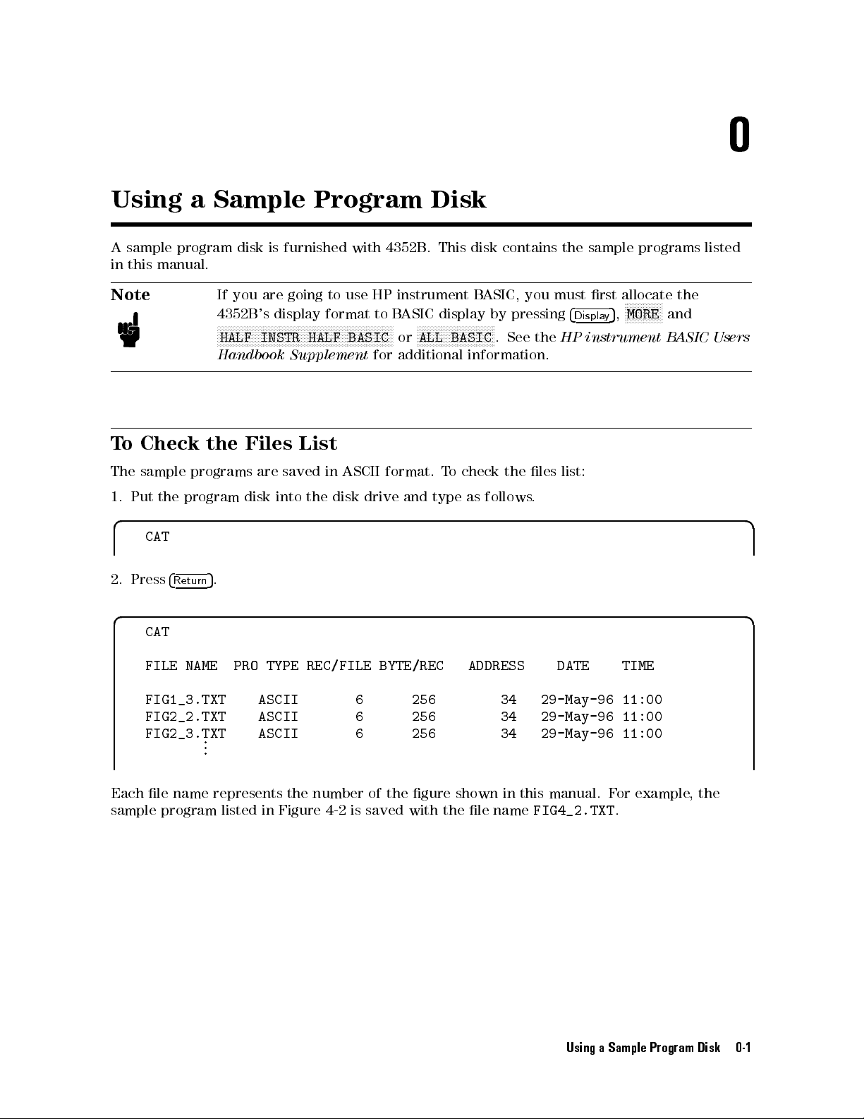
0
Using
A sample
in this
Note
T
o
Check
The
sample
1.
Put
a Sample
program
manual.
If
4352B
N
N
N
N
HALF
Handbook
the
programs
the
program
disk
you
N
N
N
N
NN
NN
Files
disk
are
's
NN
N
N
N
N
N
INSTR
are
is
display
N
N
N
into
Program Disk
furnished
going
N
N
N
N
N
N
N
N
N
N
N
NN
HALF
Supplement
to use
format
NN
NN
N
N
N
N
N
with
4352B
HP instrument
to
N
N
N
N
N
N
N
N
N
N
N
N
N
N
NN
NN
NN
BASIC
for
B
ASIC
N
or
additional
List
saved
the
in
disk
ASCII
drive and
format.
.
N
N
N
N
N
N
N
N
ALL
type as
This
disk
BASIC,
display
NN
NN
NN
N
N
N
N
N
N
N
N
N
N
BASIC
information.
To
check the
contains
by
pressing
N
N
N
N
N
.
See
follows
the
you must
4
the
HP
les
list:
.
sample
rst
Displa
allocate
N
MORE
5
,
y
programs
N
N
N
N
N
N
instrument B
N
N
NN
NN
N
and
ASIC Users
listed
the
d a
CAT
2.
Press
4
Return
5
.
d a
CAT
FILE NAME
FIG1_3.TXT
FIG2_2.TXT
FIG2_3.TXT
Each le name represents the number of the gure shown in this manual. F
sample program listed in Figure 4-2 is saved with the le name
PRO
TYPE
REC/FILE
ASCII
ASCII
.
.
.
ASCII
BYTE/REC
6
6
6
256
256
256
ADDRESS
34
34
34
DATE
29-May-96
29-May-96
29-May-96
FIG4_2.TXT
TIME
11:00
11:00
11:00
or example
.
,the
Using a Sample Program Disk 0-1
Page 10
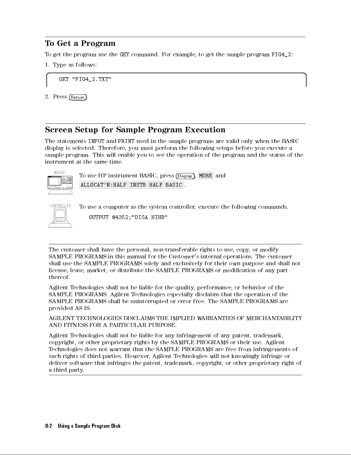
To
T
1.
o
Get a
get
the
Type
Program
program use
as
follows:
the
GET
command. F
or example
,to
get the
sample program
FIG4_2
:
d a
GET
"FIG4_2.TXT"
2.
Press
4
Screen
The
statements
display
sample
is selected.
program.
instrument
The
customer
SAMPLE
shall
use
license
,
thereof.
5
.
Return
Setup
INPUT
for
and
Therefore,
This
will enable
at
the
same
time.
T
o
use
HP
NN
NN
NN
N
N
N
instrument
N
N
N
N
N
N
N
N
N
N
N
N
N
N
N
N
N
NN
ALLOCAT'N:HALF
T
o
use
a
computer
OUTPUT
shall
have
PROGRAMS
the
SAMPLE PROGRAMS
lease
, market,
in
or distribute
Sample
PRINT
you must
N
N
N
N
N
N
N
NN
NN
NN
NN
N
N
N
N
INSTR
@4352;"DISA
the
personal, non-transferable
this
manual
used in
you to
B
N
N
N
N
N
N
N
N
as
the
ASIC,
N
N
N
Program
the
perform
see
N
N
NN
NN
NN
NN
N
N
N
N
N
HALF
system
HIHB"
for the
solely and
the SAMPLE
Execution
sample
the
programs
the
following
operation
N
5
press
N
N
N
N
N
N
N
N
N
N
N
BASIC
controller
4
N
NN
NN
NN
Displa
NN
N
N
.
,
y
,
execute
Customer's internal
exclusively for
PROGRAMS or
are
setups
of
the
N
N
N
N
N
N
NN
N
N
N
N
N
MORE
and
rights to
their own
valid
only
before
program
the
following
use
,
copy
operations
purpose
modication
when
you
and
the
commands.
,
or
modify
.
The
of
the
B
execute
status
customer
and
shall
any
part
ASIC
a
of
not
the
Agilent
SAMPLE
SAMPLE
provided
AGILENT TECHNOLOGIES DISCLAIMS THE IMPLIED W
AND FITNESS FOR A P
Agilent T
copyright,
T
echnologies does not warrant that the SAMPLE PROGRAMS are free from infringements of
such rights of third parties
Technologies
PROGRAMS. Agilent
PROGRAMS shall
AS
IS.
shall not
be uninterrupted
be
liable
for
Technologies
the
quality
especially
or error
,
performance
disclaims
free.
The
,
or
that
the
SAMPLE
behavior
operation
PROGRAMS
of
of
ARRANTIES OF MERCHANT
ARTICULAR PURPOSE.
echnologies shall not be liable for any infringement of any patent, trademark,
or other proprietary rights by the SAMPLE PROGRAMS or their use
. However
, Agilent T
echnologies
will not knowingly infringe or
. Agilent
the
the
are
ABILITY
deliver software that infringes the patent, trademark, copyright, or other proprietary right
a third party.
0-2 Using a Sample Program Disk
of
Page 11
Contents
0.
Using
T
T
Screen
1.
Overview
Required
T
GPIB
T
To
T
Query
2.
Triggering
T
Single
T
Using
a
Sample
o
Check
o
Get
a
Setup
o
Prepare
Commands
o
Execute
Program a
Set
I/O
Set
Up
Connecting
Trigger
Transfer
o
Execute
Commands
o
Measure
Set
Trigger
Start
Continuous
measurement
o
Trigger
Set
Trigger
Trigger
Set
Trigger Source
Trigger
an External
Selecting
Measurement Trigger
Program
the
Files
List
Program
of
Equipment
for
an
P
ath
the
a
Measurement
Data
an
4352B
Continuously
a Measurement
a
Measurement
a Measurement
Trigger
.
for
Sample
GPIB
Remote
GPIB
Control
Introduction
GPIB
Command
Basic
Measurement
.
.
.
Measurement
a
Device
.
.
GPIB
Command
.
Source
Measurement
Source
Trigger .
Source
Disk
.
.
.
.
.
.
.
.
.
.
.
.
.
.
.
.
.
.
.
Program
.
.
.
.
.
.
P
.
.
.
.
.
.
.
.
.
.
.
.
..
.
.
.
From the
.
.
..
.
..
.
..
...... ......
Execution
Control
.
.
.
.
.
.
.
.
.
.
.
.
.
.
.
.
arameters
.
.
.
.
.
.
.
.
.
.
.
.
with
.
.
.
.
.
.
.
.
..
.
Sweep
..
..
..
..
.
..
..
.
.
.
.
.
.
.
..
..
.
.
.
.
System
.
.
.
.
.
.
.
.
.
.
.
.
.
.
.
.
..
.
.
.
.
.
.
.
.
.
.
a
P
arameter
.
..
.
.
.
.
.
.
.
.
.
Controller .
.
.
..
.
.
.
.
.
.
.
.
..
.
.
.
.
..
.
.
.
.
.
.
.
.
.
.
..
.
.
.
.
.
.
.
.
.
.
.
..
.
.
.
..
.
.
.
.
.
.
.
.
.
.
.
.
.
.
..
..
..
..
.
.
.
.
.
..
..
..
.
.
.
.
.
.
.
.
.
.
.
.
.
.
.
.
.
..
.
..
..
..
.
.
.
.
.
.
.
..
..
..
.
.
.
.
.
.
.
.
.
.
.
.
.
..
..
.
.
.
.
.
.
.
.
.
.
.
..
.
.
.
.
.
.
.
.
.
.
.
.
.
..
..
.
.
.
.
.
.
.
.
.
.
.
.
.
.
.
.
.
..
..
..
..
.
.
.
..
..
.
.
.
.
.
.
.
.
.
.
..
..
.
.
.
.
.
.
..
..
.
.
.
.
.
.
.
.
.
..
.
.
.
.
.
.
.
.
.
.
.
.
.
.
.
.
.
.
.
.
.
.
.
.
.
.
.
.
.
.
.
.
.
.
.
.
.
.
.
.
.
.
.
.
.
.
..
.
.
.
.
.
.
.
.
.
.
.
.
.
.
.
.
.
.
.
.
.
.
.
..
.
.
.
.
.
.
.
.
.
.
.
.
.
.
.
.
.
.
.
.
.
.
.
.
.
.
.
.
.
.
.
.
.
.
.
.
.
.
.
.
.
.
..
..
..
.
.
.
.
.
.
.
.
.
..
..
.
.
.
.
.
.
.
..
..
..
.
.
.
.
.
.
.
..
.
.
.
.
...... ...... ...
.
.
.
.
..
.
.
.
.
.
.
.
.
..
.
.
.
.
.
.
.
.
.
.
.
.
.
.
.
.
.
.
.
.
.
.
.
.
.
.
.
..
..
..
.
.
.
.
.
.
..
.
.
.
.
.
.
.
.
..
.
.
.
.
.
.
.
.
.
.
.
.
.
.
.
.
..
.
.
.
. 2-3
.
.
..
.
.
.
.
..
..
.
.
0-1
0-2
0-2
1-1
1-2
1-4
1-4
1-5
1-7
1-7
1-7
1-7
1-7
1-8
1-8
2-3
2-3
2-3
2-4
2-4
2-4
2-5
2-5
2-5
2-5
2-5
3. Synchronizing the Controller with 4352B
ToW
ait For the Preceding Operation to Complete
Let
Controller W
W
aiting for Measurement Completion When Triggering a Measurement From the
External Controller . . . . . . . . .
Enabling the Measurement Completion Bit
Enable SRQ Interrupt ...... ...... ...... ...... ... 3-4
Wait Until Measurement Is Done ...................... 3-5
GenerateSRQ ............................... 3-5
To Report Command Error Occurrence .................... 3-6
Enable Error Bit . . . . . . . . . . . . . . . . . . . . . . . . . . . . . . 3-6
Report Command Error .......................... 3-7
Output Error .... ...... ...... ...... ...... ... 3-8
ait For Operation to Complete (OPC) . . . . . . . . . . . . .
...................
..............
.......
..........
. 3-2
3-2
3-3
3-3
Contents-1
Page 12
Return
4.
Loading Measurement
Data
Loading
Transferring
Transferring
Loading
Transferring
Transferring
Loading
Transferring
Transferring
Reading
Searching
Loading Data
to Execute
Formats
Measurement Data
Source
Setting
Setting
Loading
Setting
Setting
Loading
A
Specifying
Specifying
Setting
Loading
Specifying
Specifying
Setting
A
P
Specifying
Setting
Transferring
Specifying
Specifying
Setting
Loading
Transferring
Automatic
T
ester
Data
Data
T
ester
Data
Data
Measurement
utomatic
Data
Data
Data
Measurement
utomatic
assing
Control
up GPIB
Data
Data
Data
for
GPIB command
Data
.
.
.
.
Control
Data
in
ASCII
Mode
Transfer
.
.
.
Data
in
Binary
Mode
Transfer
.
.
.
Data
Control
Data
Array
Analyzer
Data
Array
Analyzer
Control
Data
Array
Array
Analyzer
Data
Using
Function
in
ASCII
.
.
Mode
Transfer
.
.
.
in
Binary
.
..
Mode
Transfer
Data
Function
in
ASCII
.
.
.
.
.
.
Data .
.
.
Mode
Transfer
.
.
.
Data
Maximum
........
in
the
.
Binary
Marker
into
.
.
.
in
T
Function
F
ormat
.
.
.
F
ormat
.
.
.
F
.
.
.
F
ormat
.
.
.
in
Analyzer
F
ormat
.
.
.
F
ormat
.
.
.
F
..
Format
in
Analyzer
F
ormat
.
.
.
.
.
.
.
.
.
.
.
.
.
.
.
F
ormat
.
.
.
.
.
.
F
V
alue
.
.
.
.
.
.
.
.
.
.
.
.
.
..
..
..
Controller
.
.
.
.
..
..
..
..
..
..
..
.
.
.
ester
Mode
(When
Is
Not
.
.
.
.
.
.
.
.
.
.
.
.
.
.
.
.
.
.
.
.
ormat
Is
ormat
Is
ormat
Search
.
.
.
.
.
.
..
..
.
.
.
.
.
.
.
.
.
..
Mode
Not
Used)
.
.
..
.
.
.
..
..
.
.
.
.
.
.
.
.
.
.
.
.
..
..
..
.
.
.
.
.
.
.
.
.
..
..
.
.
..
.
.
.
Mode (When
Used) .
.
.
.
.
.
.
.
.
.
.
.
.
.
.
.
.
.
.
.
.
.
.
.
.
..
.......................
.
.
.
.
.
.
.
.
.
.
.
.
.
.
.
.
.
.
.
.
.
.
.
.
Function .
.
.
.
.
.
.
.
.
.
.
.
.
.
.
.
Used)
.
.
.
..
.
.
..
.
.
..
..
..
(When
.
..
.
.
.
.
.
.
..
.
.
.
.
.
.
.
.
.
.
.
.
.
.
.
.
.
.
.
.
.
.
.
.
.
.
.
.
.
.
.
.
the
.
.
..
.
.
..
.
.
..
..
..
.
.
..
.
.
.
.
.
.
.
.
..
.
.
.
.
.
.
.
.
.
.
.
.
.
.
.
.
.
.
.
..
.
.
.
.
..
.
.
.
.
..
.
.
4352B
.
.
.
.
.
..
..
..
..
..
..
..
..
.
..
..
.
.
.
..
..
.
.
.
.
External
.
.
..
.
.
.
.
.
.
.
.
.
..
.
.
..
.
.
.
.
..
..
.
.
.
.
.
.
.
.
.
.
.
.
External
.
.
.
.
.
.
.
.
.
.
.
.
.
.
.
.
.
.
.
.
.
.
.
.
..
.
.
..
..
.
.
..
..
..
..
..
.
.
.
..
..
..
.
.
.
.
's
External
.
.
..
.
..
.
.
..
.
.
.
.
.
.
Signal
..
.
.
.
.
.
.
.
.
.
.
.
.
.
.
.
.
.
.
Signal
.
.
.
.
.
.
.
.
.
.
.
.
.
.
..
..
.
.
..
..
..
..
..
..
.
.
..
.
.
..
.
.
.
.
.
.
..
.
.
.
.
.
.
.
.
.
.
.
.
.
.
.
.
.
.
.
.
.
.
..
.
..
..
.
.
.
.
..
..
.
.
..
..
..
.
.
Signal
..
.
.
.
.
.
.
.
.
.
.
.
.
.
.
Source
.
.
.
.
.
.
.
.
.
.
.
.
.
.
.
.
.
.
.
.
Source
.
.
.
.
.
.
.
..
..
.
.
.
.
.
.
.
.
.
..
.
.
.
..
.
.
.
.
.
.
.
.
.
.
.
.
.
.
.
.
.
.
.
..
.
.
.
..
.
.
.
.
.
.
.
..
.
.
..
.
.
.
.
.
.
.
.
.
.
.
.
.
.
.
.
.
.
.
.
.
.
.
.
.
.
.
.
.
.
..
.
.
.
.
.
.
.
.
.
.
.
.
.
.
.
.
.
.
.
.
.
.
.
.
.
.
.
.
.
.
3-8
.
4-2
4-3
.
4-3
.
4-5
.
4-5
.
4-5
.
4-6
.
4-7
.
4-7
.
4-7
.
4-9
.
4-9
.
4-10
.
4-10
.
4-10
.
4-10
.
4-11
. 4-12
.
4-12
.
4-12
.
4-13
.
4-13
.
4-13
.
4-13
.
4-13
.
4-13
.
4-15
.
4-15
.
4-15
.
4-15
.
4-15
.
4-16
.
4-18
.
4-18
4-18
5. Printing the 4352B's Display
To Print Analyzer Display
Printer Preparation .. ...... ...... ......
Execute Print ...... ...... ...... ...
To Observe Printing
Contents-2
...... ...... ...... ..
.................
..........
...... ...
...... ..
...... ...
5-1
5-1
5-1
5-1
Page 13
6.
Remote Controlling
T
o Control
T
o Execute
T
o Run
Open
Transfer
Close
Run
T
o
Transfer
Open
Transfer
Close
7.
If
Y
ou
If
There
If
an
If
Y
ou
If
the
8.
The
Status
OSPT
OSPT
OSNT
9.
Command
Command
AFC
AFCITER
AFCMAXV
AFCMINV
AFCSENS
AFCT
AFCTOL
A
VER
A
VERF
A
VERREST
CNBW
CNOFREQ
CONT
CTRLDL
CTRLVCAL .......
CTRLVCORRtfOFFj0jONj1
DATGAINt<
DATMEM ...................
DATOVALt<
DEFGO .. ...... ...... ...... ..
DEVCAL ......................
DEVCALF?t<
DEVCORRtfOFFj0jONj1g...... ...... ...... ..... ... 9-8
DEVRNGtfDV200KHZjDV20KHZjDV2KHZg...... ...... ..... 9-8
DHOLDtfOFFjMAXjMINg...... ...... ..... ...... .. 9-9
DISPtfDATAjMEMOjDATMg...... ..... ...... ...... . 9-9
DNCONVtfOFFj0jONj1g.......................... 9-9
DTHPFtfFC50HZjFC300HZg...... ...... ..... ...... . 9-10
DTLPFtfFC3KHZjFC15KHZjFC20KHZg................... 9-10
GPIB
an
HP
an
HP
instrument
the HP
the HP
the
HP
the
HP
instrument
Program
the
HP
the
the
HP
Have
a
Problem
Is
No
Response
Error
Message
Cannot
GPIB
,
OSNT
tf
ARG
tf
Get
Command
Report
.
(Operation Status
(Operation
Reference
Reference
OFF
j
0
j
t
<
numeric
t
<
t
<
t
<
numeric
t
<
t
<
numeric
OFF
j
0
A
CT
t
<
t
<
numeric
t
<
.
.
.
Y
t
<
numeric
numeric>...... ...... ..
numeric>...... ...... .
HP instrument
from
HP
instrument
instrument
instrument
instrument
instrument
to
instrument
Program
instrument
is
Displayed
a
File
Does
System
.
.
.
.
Status
for T
.
ON
j
1
g
>
numeric
numeric
>
numeric
>
j
ON
j
1
g
numeric
.
.
.
.
>
numeric
.
.
..
>
numeric>...... ...... ...... .
B
ASIC
B
ASIC
B
ASIC
B
B
ASIC
B
ASIC
HP
instrument
B
ASIC
.
.
.
B
ASIC
From
an
from
the Disk
Not
.
..
..
Positive
Negative Transition
ester Mode
.
.
..
.
.
.
.
.
.
.
>
.
.
>
.
.
.
.
.
>
.
.
.
.
.
.
.
.
..
>
.
.
.
.
.
.
.
.
.
.
>
.
.
..
..
.
.
.
.........................
g
...... ...... ...... ......
B
ASIC
B
ASIC
Command
Program
Editor
ASIC
Editor
Program
Editor
.
.
Editor
Instrument
.
W
ork
..
Transition Filter)
.
.
.
.
.
.
.
.
.
.
.
.
.
.
.
.
..
.
.
.
.
.
.
.
..
..
.
.
From
Program
B
ASIC
.
.
.
.
.
.
..
.
.
.
.
.
.
.
.
.
.
.
.
.
.
.
.
.
.
.
.
.
.
.
.
.
.
.
.
..
.
.
.
.
.
.
.
.
.
..
..
..
.
.
.
.
.
.
.
.
.
.
..
.
.
.
.
.
.
.
.
.
..
.
.
.
..
.
.
.
.
.
From
the
.
.
.
.
.
.
.
.
.
.
.
.
.
.
.
.
.
.
.
.
.
.
.
..
.
.
..
on
the
.
..
..
.
.
..
.
.
.
Filter) .
.
.
.
.
.
.
..
.
.
.
.
.
.
.
.
.
.
.
.
.
.
.
.
.
.
.
..
.
.
.
..
..
..
..
.
..
..
.
.
.
.
.
.
.
..
..
..
the
External
External
.
.
.
.
.
.
.
..
..
GPIB
..
.
.
.
.
.
..
.
.
.
.
.
.
.
.
.
.
.
..
..
..
.
.
.
.
..
..............
..............
Controller
.
..
..
.
.
.
..
.
..
..
.
..
..
.
..
..
.
..
..
..
..
..
..
Bus
..
..
.
.
.
.
.
.
.
.
.
.
.
.
.
.
.
.
.
.
.
.
.
.
.
.
.
.
.
.
.
.
.
.
.
.
.
.
.
.
.
.
..
.
.
.
.
.
.
.
.
.
.
.
.
.
.
.
.
.
.
.
.
.
.
.
.
.
.
.
.
.
.
.
.
.
.
.
.
.
..
..
.
.
.
.
.
.
.
.
.
.
.
.
.
.
.
.
.............
............
...... .....
..
..
Controller
.
..
..
..
..
..
..
..
..
..
.
..
..
.
..
..
.
..
..
.
.
.
.
.
.
.
.
.
.
.
..
..
.
.
.
.
.
.
.
.
.
.
.
.
.
.
.
.
.
.
.
.
.
.
.
.
.
.
.
.
.
.
.
.
.
.
.
.
.
.
.
.
.
.
.
.
.
..
.
.
.
..
.
.
..
..
.
..
..
.
.
.
.
.
.
.
.
.
.
.
.
.
.
.
.
.
.
.
.
.
.
.
.
.
.
.
.
.
.
.
.
.
.
..
.
.
.
.
.
.......
..
.
..
..
..
..
.
.
.
.
.
.
.
.
.
.
.
.
.
.
.
.
.
.
.
.
.
..
.
.
.
.
.
.
.
.
.
.
.
.
.
.
.
.
.
.
.
.
.
.
.
.
.
.
.
.
.
.
..
..
. 6-1
6-4
6-5
6-5
6-5
.
6-5
.
6-6
.
6-6
.
6-6
.
6-7
.
6-7
.
7-1
.
7-1
.
7-2
.
7-3
8-6
.
8-6
.
8-6
. 9-3
.
9-3
.
9-3
.
9-3
.
9-4
.
9-4
.
9-4
.
9-5
.
9-5
.
9-5
.
9-5
.
9-6
.
9-6
. 9-6
.
9-6
9-7
. 9-7
9-7
9-7
9-7
9-8
9-8
9-8
Contents-3
Page 14
FB
AND
t
<
numeric
FCOUN
HOLD
INPUD
LCOMP
LO
LOFREQ?
LOSS
LOSWT
MA
MAXV
MEAS
MINV
MOD
MODO
NA
NOMFREQ
OUTPD
OUTPMEMO?
P
ARM
PKCONV
POWUNIT
PRES
REST
RF
SGCMD
SGTYPE
SIGSRCH
SING
SLOPE
TRGP
TRGS
V
A .
V
V
VPOW
AUTO
TH
AMP
TT
A
TT
CTRL
OUT
tf
..
AT
tf
tf
t
<
numeric
t
<
tf
D
CTRL
tf
POWE
CTRL
tf
OFF
t
<
numeric
A
T
tf
OFF
tf
.
.
t
<
t
<
tf
.
t
<
tf
POS
tf
INT
.
t
<
tf
OFF
t
<
RES1KHZ
.
A
t
OFF
OFF
.
numeric
A
T
t
t
<
t
A?
OFF
tf
.
..
.
..
numeric
Character
1
.
.
.
numeric
.
.
numeric
numeric
.
.
.
<
numeric
j
0
j
ON
j
ON
.
.
.
>
A
j
DPLM
t
<
numeric
j
FREQ
<
numeric
numeric
j
0
j
ON
>
<
numeric
.
.
.
.
.
j
0
j
ON
j
0
j
DBM
j
..
..
j
2
j
3
j
4
g
.
.
.
.
.
.
j
NEG
g
j
EXT
j
BUS
.
.
.
j
0
j
ON
>
.
.
j
RES64KHZ
.
.
.
>
j
1
g
.
j
0
j
1
g
.
.
.
.
.
.
>
.
.
j
DMNM
>
j
CURR
>
>
.
j
1
g
.
.
.
.
>
.
.
.
.
.
.
j
1
g
.
.
ON
j
1
g
DBV
j
DBUV
.
.
.
.
.
.
>
.
.
String
.
.
.
.
.
.
.
.
.
>
.
.
.
.
.
j
MAN
.
.
.
>
.
.
j
1
g
.
.
>
.
.
.
.
.
.
.
.
.
.
.
.
.
.
.
.
.
.
j
DDVM
.
.
j
FMDEV
.
.
.
.
.
..
.
.
.
.
..
.
.
.
.
.
..
j
W
.
.
.
.
.
.
>
,
.
.
.
.
.
.
.
.
.
.
g
.
.
.
.
.
.
.
.
.
.
.
g
.
.
.
.
.
..
..
..
.
.
.
.
.
.
.
.
.
.
.
.
.
.
.
.
.
..
.
..
.
.
.
..
.
.
.
.
.
..
..
j
V
g
.
.
.
.
.
.
.
.
.
<
Divider
.
.
.
.
.
.
.
.
.
.
.
.
.
.
.
.
.
.
.
.
..
.
.
.
.
.
.
..
.
.
..
.
.
.
g
.
j
CN
..
..
..
..
.
.
.
.
.
.
.
.
.
.
.
.
.
.
.
.
.
.
.
.
.
.
..
.
.
.
.
.
..
..
..
..
..
..
.
..
..
.
.
g
..
..
.
..
.
..
.
.
.
.
.
.
.
.
..
.
.
.
.
.
.
>
.
.
.
.
.
.
.
.
.
.
.
.
.
.
..
..
.
.
.
.
.
.
..
..
..
..
..
..
..
..
..
..
..
..
.
.
.
..
.
.
.
..
.
.
.
.
..
.
.
.
.
.
.
.
.
.
.
.
.
.
.
.
.
.
.
.
.
.
.
..
.
.
..
..
.
.
..
..
..
..
..
..
..
..
..
..
..
.
.
.
.
.
..
.
.
.
.
.
.
.
.
.
.
.
.
.
.
.
.
.
.
.
.
.
.
.
.
.
.
.
.
.
.
.
..
.
.
..
..
..
..
..
..
..
..
..
..
..
..
..
.
.
.
.
.
.
.
.
.
.
.
.
.
.
.
.
.
.
.
.
.
.
.
.
.
.
.
.
.
.
.
.
.
.
.
.
.
.
.
..
..
.
.
..
..
..
..
..
..
..
.
.
.
.
.
.
.
..
.
.
.
.
.
.
.
.
.
.
.
.
.
.
.
.
.
.
.
.
.
.
.
.
.
.
.
.
.
.
.
.
..
..
.
.
.
..
.
.
..
.
.
.
.
.
.
..
..
..
..
.
.
.
.
.
.
.
.
.
.
.
.
.
.
.
.
.
.
.
.
.
.
.
.
.
.
.
.
.
.
.
.
.
.
.
.
.
.
.
.
.
.
.
..
.
.
.
.
..
..
..
.
.
.
.
.
.
.
.
.
..
..
.
.
..
.
.
.
.
.
.
.
.
.
.
.
.
.
.
.
.
.
.
.
.
.
.
.
.
.
.
.
.
.
.
.
.
.
.
.
.
..
..
.
..
.
.
.
.
.
.
.
.
.
..
.
.
.
.
.
.
.
.
..
..
.
.
.
.
.
.
.
.
.
.
.
.
.
.
.
.
.
.
.
.
.
.
.
.
.
.
.
.
.
.
.
.
.
.
.
.
.
.
.
.
..
..
..
.
.
.
.
.
.
.
.
.
.
.
.
.
.
.
.
.
.
.
.
.
.
.
.
..
.
.
.
.
.
.
.
.
.
.
.
.
.
.
.
.
.
.
.
.
.
.
.
.
.
.
.
.
.
.
.
.
.
.
.
.
.
.
.
.
.
.
.
.
.
.
.
.
.
.
.
.
.
.
.
.
.
.
.
.
.
.
.
.
.
.
.
.
.
..
.
.
.
.
.
.
.
.
.
.
.
.
.
.
.
.
.
.
.
.
.
.
.
.
.
.
.
.
.
.
.
. 9-15
.
.
.
.
..
.
.
.
.
.
.
.
.
.
.
.
.
.
.
.
.
.
.
.
.
.
.
.
.
.
.
.
.
.
.
9-10
9-11
9-11
9-11
9-11
9-12
9-12
9-12
9-12
9-13
9-13
9-13
9-14
9-14
9-14
9-14
9-15
9-15
9-15
9-16
9-16
9-16
9-16
9-17
9-17
9-17
9-18
9-18
9-18
9-18
9-19
9-19
9-19
9-19
9-20
10.
Command
Command
Contents-4
Reference
Reference
AFC
tf
OFF
j
0
j
ON
AFCITERt<
AFCMAXVt<
AFCMINVt<
AFCSENSt<
AFCTARGt<
AFCTOLt<
AUTO.......... ...... ......
AVERtfOFFj0jONj1g...... ..... ...
AVERFACTt<
AVERREST ................................ 10-5
BEEPFAILtfOFFj0jONj1g...... ...... ...... ..... .. 10-6
BWt<
CARRCENT ..... ..... ...... ...... ...... .... 10-6
CARR2CENT ............................... 10-6
CARR3CENT ............................... 10-6
numeric>.....
numeric>......
numeric
numeric>...... ...... .....
numeric
numeric>..................
numeric>...... ...... ...... ...... ...... 10-6
for
Analyzer
.
.
.
.
..
j
1
g
.
.
.
.
>
...... .
>
................
numeric>...... ...... ...... ..... ... 10-5
Mode
..
..
..
..
..
.
.
.
.
.
.
.
.
.
.
.
.
.
..
.
.
.
.
.
.
.
.
.
.
..
.
.
..... ..... ...... ......
....................
...................
..........
..........
.........
...... ...... .
..............
.
.
.
.
10-3
.
.
.
.
10-3
10-3
10-3
10-4
10-4
10-4
10-5
10-5
10-5
Page 15
CARR?
CENT
CLRSMKRS
CNBW
CNPLL
CONT
CTRLDL
CTRL
CTRL
D
A
TGAIN
D
A
TLIML
D
A
TLIMU
D
A
TMEM
D
A
TO
DEFGO
DET
DHOLD
DISP
DMKR
DMKRPRM
DNCONV
DMKRV
EXD
EXD
FB
AND
FCOUN
HOLD
INPUD
INPULIML
INPULIMU
INTGNOIS?
LCOMP
LIMCLEL
LIMILINE
LIMIST
LIMITEST
LIMSECT
LIMSECTN
LOAUTOtfOFFj0jON
LOFREQ? .... ..... .
LOSSt<
LOSWTt<
MAXVCTRLt<
MEAINOIStfOFFj0jONj1g...... ...... .
MEAStfPOWEjFREQjNOISjTRANjSPECg............
MINVCTRLt<
MKRtfOFFj0jONj1g............................ 10-18
MKRCENT .... ...... ...... ...... ..... ..... 10-18
MKRCONTtfOFFj0jONj1g......................... 10-18
MKRLtfOFFj0jONj1g............................ 10-19
MKROtfDATAjMEMOg........................... 10-19
MKRPt<
MKRPRMt<
..
..
.
.
.
.
.
.
.
.
.
.
.
.
.
..
..
..
..
..
..
.
.
t
<
numeric
t
<
numeric
tf
A
UTO
..
Y
t
<
V
CAL
V
CORR
t
<
V
AL
t
<
.
tf
POS
j
tf
OFF
tf
D
A
T
tf
ON
t
tf
AL
t
A
TLIML
A
TLIMU
t
<
numeric
tf
RES1KHZ
.
.
A
T
A
t
t
t
tf
OFF
tf
A
T?
tf
t
<
<
LowLmt2
t
<
LowLmt2
numeric>...... .
numeric>........
numeric>............................ 10-19
>
.
.
.
.
.
.
.
.
.
..
..
..
..
..
..
..
.
.
..
.
.
.
.
.
.
.
.
.
.
.
..
..
..
..
..
..
..
.
.
>
.
.
.
.
.
.
.
.
.
..
..
..
..
..
..
..
.
.
j
WIDE
g
.
.
.
.
.
.
.
..
..
..
..
..
..
..
.
.
.
.
.
.
.
.
.
.
.
.
.
.
..
..
..
..
..
..
..
.
.
.
.
.
numeric
.
tf
numeric
.
.
.
.
.
.
numeric
.
.
NEG
j
A
j
MEMO
j
FIX
<
numeric
OFF
<
numeric
..
..
.
.
<
numeric(1)
<
numeric(1)
<
numeric(1)
..
j
0
..
OFF
.
OFF
P
aram1
>
<
P
>
numeric>...... ...... ..... ..
numeric>...... ...... ...... ...... ... 10-19
>
.
.
.
.
.
.
.
.
..
..
..
..
.
.
.
.
.
.
.
.
.
.
.
..
..
..
..
.
.
.
OFF
j
0
j
ON
j
1
g
.
.
..
..
..
..
.
.
.
.
.
>
.
.
.
.
.
.
.
..
..
..
..
.
.
.
.
.
.
.
.
.
.
.
..
..
..
..
.
.
.
.
.
.
.
.
.
..
..
..
..
.
.
.
.
.
.
.
.
.
.
.
.
.
..
..
..
..
.
.
.
.
.
.
.
.
>
.
.
.
..
..
..
.
.
.
.
.
.
.
.
.
.
.
.
.
.
.
.
..
..
..
.
.
.
.
.
.
.
j
SAM
g
.
.
.
.
..
..
..
.
.
.
.
.
.
.
MAX
j
MIN
g
.
.
.
.
..
..
..
.
.
.
.
.
j
D
ATM
g
.
.
.
.
.
.
.
.
.
.
.
.
.
.
j
TRA
C
j
OFF
g
.
.
.
.
..
.
.
.
.
.
.
.
.
>
.
.
.
.
.
.
.
.
.
.
.
..
.
.
.
j
0
j
ON
j
1
g
.
..
..
.
.
.
.
.
.
.
.
.
.
.
>
.
.
.
..
..
..
..
.
.
.
.
.
..
.
.
.
.
.
.
.
.
.
.
.
.
.
.
.
.
.
.
..
.
.
.
.
.
.
.
.
.
.
.
.
.
.
.
.
.
.
>
.
.
.
.
.
.
.
.
.
.
.
.
.
.
.
.
.
.
j
RES64KHZ
..
.
.
.
.
.
.
.
j
ON
j
1
g
.
.
.
.
.
.
j
0
j
ON
j
1
g
.
.
.
.
.
j
0
j
ON
j
1
g
>
,
<
.
.
.
.
aramN1
numeric>...... ...... ....
>
.
.
..
j
1g..... ..... ...... ...... .
.
.
.
>
,
<
numeric(2)
>
,
<
numeric(2)
>
,
<
numeric(2)
.
.
.
.
.
.
.
.
.
.
.
.
.
.
.
.
.
.
UpLmt1
.
.
.
,
<
UpLmt1
.
.
.
g
.
.
.
.
.
.
.
.
.
.
.
.
.
.
.
.
.
.
.
.
.
.
.
.
.
>
,
.
.
.
<
numeric(n)
>
,
.
.
.
<
numeric(n)
>
,
.
.
.
<
numeric(n)
.
.
.
.
.
.
.
.
.
.
.
.
.
.
.
.
.
.
.
.
.
.
.
..
..
.
.
.
.
.
.
.
.
.
.
.
.
.
.
..
..
..
..
.
.
.
.
.
.
.
.
..
..
..
.
.
.
.
.
.
..
..
..
.
.
.
.
>
,
<
LowLmt1
.
.
.
.
>
,
<
.
.
.
.
.......................
...
..... ..... ...... ....
>
,
<
Param2
.
.
..
..
..
..
LowLmt1
.
.
...... .....
>
,
<
ParamN2
.
.
..
.
.
.
............
.
.
.
.
.
.
.
.
.
.
.
.
.
.
.
.
.
.
.
.
.
.
.
.
.
.
.
.
.
.
.
.
.
.
.
.
.
.
.
.
.
.
.
.
.
.
.
.
.
.
.
.
.
.
.
.
.
.
.
.
.
.
.
.
.
.
.
.
.
.
.
.
.
.
.
.
.
.
.
.
.
.
.
.
.
.
.
.
.
.
.
.
.
.
.
.
.
.
.
.
.
.
.
.
.
.
.
.
.
.
.
.
.
.
.
.
.
.
.
.
..
..
.
.
.
.
..
..
.
.
.
.
..
..
.
.
.
.
.
.
.
.
.
.
.
..
.
>
.
.
.
.
..
>
.
.
.
.
.
.
>
.
.
.
.
.
.
..
..
.
.
.
.
.
.
.
.
.
..
..
.
.
.
.
.
.
.
.
.
.
.
.
.
.
.
.
.
.
.
.
.
.
.
.
.
>
,
<
UpLmt2
.
.
>
.
.
.
...... ..
...... ....
>
,
.
.
.
.
.
,
<
UpLmt2
.
.
.
.
..
...
......
...... .
.
.
.
.
.
.
.
.
.
.
.
.
.
.
.
.
.
.
.
.
.
.
.
.
.
.
.
.
.
.
.
.
.
.
.
.
.
.
.
.
.
.
.
..
.
.
..
.
.
.
.
.
.
.
.
.
.
.
.
.
.
.
.
>
.
10-6
.
10-7
.
10-7
.
10-7
.
10-7
.
10-8
.
10-8
.
10-8
.
10-8
.
10-8
.
10-9
. 10-9
. 10-9
.
10-9
.
10-9
.
10-9
.
10-10
10-10
.
10-10
.
10-11
10-11
.
10-11
.
10-11
.
10-12
.
10-12
.
10-12
.
10-13
.
10-13
. 10-13
.
10-13
.
10-13
.
10-14
.
10-14
.
10-14
.
10-14
.
10-15
.
10-15
,
.
10-15
10-16
10-16
10-16
10-16
10-17
10-17
10-17
10-18
Contents-5
Page 16
MKRPRM?
MKRREF
MKRST
MKRSTOP
MKRTHRE
MKRV
MKRV
MOD
AMP
MODO
NA
TT
NOMFREQ
OUTPD
OUTPD
OUTPDMKR?
OUTPSMKR
OUTPLIML?
OUTPLIMRES?
OUTPLIMU?
OUTPMEMO?
OUTPMEMOP?
OUTPMKR?
OUTPSWPRM?
OUTPSWPRMP?
P
ARS
PKDL
PKTHRE
PKTHV
POIN
POWUNIT
PRES
PRSMKRS
REFP
REFV
REST
RF
A
TT
SA
VLIM
SCA
C
SCAF
SCAL
SEAL
SEAMtfPEAKjMAXjMINjTARG
SEANPK ..........
SEANPKL . . . . . . . . . . .
SEANPKR............
SEAR.....................
SEARSTR ...... ...... ...... ....
SEARSTRL .......................
SEARSTRR .. ...... ...... ...... ....
SEATARGt<
SENSAPERt<
SENSPOLtfPOSjNEGg........................... 10-31
SGCMDt<
SGTYPEtf1j2j3j4g...... ...... ..... ...... ...... 10-32
SING ................................... 10-32
SIGSRCH ................................. 10-32
..
..
.
.
.
.
.
.
.
.
.
.
.
.
.
..
..
..
..
..
..
.
.
..
.
.
.
.
.
.
.
.
.
.
.
..
..
..
..
..
..
..
.
.
.
.
AR .
AL? .
CTRL
tf
t
tf
TY
t
<
t
<
t
t
tf
tf
t
<
.
.
.
.
.
.
.
.
.
.
.
.
..
..
..
..
..
..
..
.
.
.
.
.
..
.
.
.
.
.
.
.
.
.
.
.
..
..
..
..
..
..
..
.
.
.
.
..
.
.
.
.
.
.
.
.
.
.
.
..
..
..
..
..
..
..
.
.
.
.
.
.
.
.
.
.
.
.
.
.
..
..
..
..
..
..
..
.
.
.
.
.
.
.
.
.
.
.
.
.
.
.
.
.
..
..
..
..
.
.
.
.
.
.
.
.
.
.
t
<
numeric
OFF
j
0
<
numeric
t
<
numeric
A
T
A?
.
A
T
AP?
t
f
1-4
.
.
.
OFF
j
0
j
ON
t
<
numeric
tf
OFF
AL
t
<
numeric
numeric
tf
DBM
.
.
.
.
..
Integer
<
numeric
.
.
.
.
<
numeric
tf
OFF
j
OFF
j
0
j
ON
D
A
T
A
j
MEMO
numeric
.
.
.
numeric>........................... 10-30
numeric>.......................... 10-31
Character String>,<Divider>.................. 10-31
j
ON
>
.
.
<
Integer
.
.
g
?
.
.
.
.
.
.
.
.
t
<
Integer
.
.
.
.
t
<
j
1
j
0
j
ON
>
j
.
.
.
.
>
>
.
.
0
j
ON
j
>
..
>
j
1
g
.
.
>
.
.
.
.
.
.
.
.
.
.
.
.
.
.
.
.
.
.
Integer
g
.
>
j
1
>
.
.
DBV
.
.
.
.
.
.
.
.
.
.
>
.
j
1
g
1
g
.
g
.
..
.
.
.
.
.
.
.
.
.
.
..
>
.
.
.
.
.
.
.
.
.
.
.
.
>
.
.
.
.
>
.
.
.
.
g
.
.
.
.
.
j
DBUV
.
.
.
.
.
.
.
.
.
.
.
.
.
.
.
.
.
.
..
.
.
.
.
.
.
.
.
..
..
..
..
.
.
.
.
.
.
.
.
.
..
..
..
..
.
.
.
.
.
.
.
.
.
.
.
.
.
.
.
..
..
..
..
.
.
.
.
.
.
.
.
.
.
.
.
.
.
.
.
.
..
..
..
..
.
.
.
.
.
..
..
..
.
.
.
.
.
.
.
.
.
.
.
.
.
.
.
.
..
..
..
..
.
.
.
.
.
.
.
.
.
.
.
.
.
.
.
.
..
..
..
.
.
.
.
.
.
.
.
.
.
.
.
.
..
..
..
.
.
.
.
.
.
.
.
.
.
.
.
.
.
.
.
..
..
..
.
.
.
.
.
.
.
.
.
.
.
.
.
.
.
.
..
..
..
.
.
.
.
.
.
.
.
.
.
.
.
..
..
.
.
.
.
.
.
.
.
.
.
.
.
.
.
.
.
.
.
.
.
.
.
.
..
.
.
.
.
.
.
.
.
.
.
.
.
.
.
.
.
.
.
.
.
.
.
..
.
.
.
.
.
.
.
.
.
..
..
..
.
.
.
.
.
.
.
.
.
.
.
.
.
.
.
.
..
..
..
..
.
.
.
.
.
.
.
.
.
.
.
..
.
.
.
.
.
.
.
.
.
.
.
.
.
.
.
.
.
.
.
.
.
.
.
.
.
.
.
.
.
.
.
.
..
..
.
.
.
.
.
.
.
.
.
.
.
.
.
.
.
.
.
.
.
.
.
.
.
..
.
.
.
.
.
.
.
.
.
.
.
.
.
.
.
.
.
.
.
..
.
.
.
.
.
.
.
.
.
.
.
.
.
.
.
.
.
.
.
.
.
.
.
.
.
.
.
.
.
.
.
.
.
.
.
..
.
.
.
.
.
j
W
j
V
g
.
.
.
.
.
.
.
.
.
.
.
.
..
.
.
.
.
.
.
.
.
.
.
.
.
.
.
.
.
..
.
.
.
.
.
.
.
.
.
.
.
.
.
.
.
.
.
.
.
.
.
..
..
.
.
.
.
.
.
.
.
.
.
.
.
.
.
.
.
.
..
..
.
.
.
.
.
.
.
.
.
.
.
.
.
.
.
.
.
..
..
.
.
.
.
.
..
..
..
..
.
.
.
.
.
.
.
.
.
.
.
.
.
.
.
.
..
..
..
.
.
.
.
.
.
.
.
.
.
.
.
..
..
..
.
.
.
.
.
.
.
.
.
.
.
.
.
.
..
..
..
..
.
.
.
.
.
.
.
.
.
.
.
.
.
.
.
.
..
..
..
..
.
.
.
.
.
.
.
.
..
..
..
..
.
.
.
.
.
.
.
.
.
.
.
.
.
.
.
.
.
.
.
..
.
.
.
.
.
.
.
.
.
.
..
j
OFFg....................
.......................
...... ...... ...... ....
...... ......
..
..............
...... .....
...... .
...... ...
...... ..
.
.
.
.
.
.
.
.
.
.
.
.
.
.
.
.
.
.
.
.
.
.
.
.
.
.
.
.
.
.
.
.
.
.
.
.
.
.
.
.
.
.
.
.
.
.
.
.
.
..
.
..
.
.
.
.
.
.
.
.
.
.
.
..
.
.
.
.
.
.
.
.
.
.
.
.
.
.
.
.
.
.
.
.
.
.
.
.
. 10-22
.
.
.
.
.
.
.
.
.
.
.
.
.
.
.
.
.
.
.
.
.
. 10-25
.
.
.
.
.
.
.
.
.
.
.
.
.
.
.
.
.
.
.
.
.
.
.
.
.
.
.
.
. 10-29
.
.
10-20
10-20
10-20
10-20
10-20
10-20
10-20
10-21
10-21
10-21
10-21
10-22
10-22
10-22
10-23
10-23
10-23
10-23
10-24
10-24
10-24
10-25
10-25
10-26
10-26
10-26
10-26
10-27
10-27
10-27
10-27
10-28
10-28
10-28
10-28
10-29
10-29
10-29
10-29
10-30
10-30
10-30
10-30
10-30
10-30
Contents-6
Page 17
SLOPE
SMKR
SMKRP
SMKRP
SMKRV
SP
ST
STOP
SWET
SWPT
TRA
TRGOUT
TRGP
TRGS
TRGV
TRMAX
TRMIN
TRREF
TRSP
TRT
TRTPOS
VBW
V
V
VPOW
VT
AN
AR
CK
AN
ARG
t
CTRL
OUT
.
f
t
t
t
t
tf
tf
tf
AL
tf
t
<
<
t
<
t
t
<
numeric
1-4
gtf
f
1-4
gt
f
1-4
g
?
AL
f
1-4
<
numeric
numeric
numeric
<
numeric
LOGF
tf
OFF
tf
OFF
POS
j
NEG
INT
j
EXT
t
<
numeric
t
<
numeric
<
numeric
t
<
numeric
tf
TS2MHZ
t
<
numeric
t
<
numeric
numeric
<
numeric
OFF
j
<
numeric
.
.
.
OFF
<
numeric
.
g
?
>
>
>
j
LINF
j
0
j
ON
j
0
j
j
>
0
j
ON
..
>
.
j
0
j
ON
.
.
.
.
.
.
.
.
.
.
.
.
>
.
g
.
j
1
g
ON
j
1
g
g
.
.
BUS
j
MAN
>
>
.
>
.
>
.
j
TS20MHZ
>
>
.
.
.
>
.
j
1
g
.
>
..
.
.
.
.
.
.
.
.
.
.
.
.
.
.
.
..
..
..
..
..
..
.
.
.
10-32
j
1
g
.
.
..
..
..
..
..
..
..
.
.
.
.
.
.
.
.
.
10-33
>
.
.
.
.
.
.
.
..
..
..
..
..
..
..
.
.
.
.
10-33
.
.
.
.
.
..
..
..
..
..
..
..
.
.
.
.
.
.
.
.
10-33
.
.
.
.
.
..
..
..
..
..
..
..
.
.
.
.
.
.
.
.
10-33
.
.
.
.
.
.
..
..
..
..
..
..
..
.
.
.
.
.
.
.
10-33
.
.
.
.
.
.
..
..
..
..
.
.
.
.
.
.
.
.
.
.
.
.
.
10-34
.
.
.
.
.
.
.
..
..
..
..
.
.
.
.
.
.
.
.
.
.
.
.
10-34
.
.
.
.
.
.
.
.
..
..
..
..
.
.
.
.
.
.
.
.
.
.
.
10-34
.
.
.
.
.
.
.
..
..
..
..
.
.
.
.
.
.
.
.
.
.
.
.
10-35
.
.
.
..
..
..
..
.
.
.
.
.
.
.
.
.
.
.
.
.
.
.
.
10-35
..
..
..
..
.
.
.
.
.
.
.
.
.
.
.
.
.
.
.
.
.
. 10-35
.
.
..
..
..
..
.
.
.
.
.
.
.
.
.
.
.
.
.
.
.
.
.
10-35
j
V
AL
g
.
..
..
.
.
.
.
.
.
.
.
.
.
.
.
.
.
.
.
.
10-36
.
.
.
.
.
.
..
..
..
.
.
.
.
.
.
.
.
.
.
.
.
.
.
.
10-36
.
.
.
.
.
.
..
..
..
.
.
.
.
.
.
.
.
.
.
.
.
.
.
.
10-36
.
.
.
.
.
.
..
..
..
.
.
.
.
.
.
.
.
.
.
.
.
.
.
.
10-36
.
.
.
.
..
..
.
.
.
.
.
.
.
.
.
.
.
.
.
.
.
.
.
.
.
10-37
j
.
.
.
.
.
.
.
.
.
.
.
.
.
TSMAX
.
.
.
..
..
.
.
.
.
.
.
.
.
.
.
..
..
.
.
.
.
.
.
.
.
g
.
.
..
..
.
.
.
.
.
.
.
.
.
.
.
.
.
..
.
.
.
.
.
.
.
.
.
.
..
.
.
.
.
.
.
.
.
.
.
.
.
.
.
..
.
.
.
.
.
.
.
.
.
.
.
10-37
.
.
.
.
.
.
.
.
.
.
.
.
.
.
.
10-37
.
.
.
.
.
.
.
.
.
.
.
.
.
.
.
10-38
.
.
.
.
.
.
.
.
.
.
.
.
.
.
.
10-38
.
.
.
.
.
.
.
.
.
..
..
.
.
10-39
.
.
.
.
..
..
.
.
.
.
.
.
.
10-39
.
.
.
.
.
.
.
.
.
.
..
..
.
10-39
.
.
.
.
.
.
.
.
..
.
.
.
.
.
10-39
11.
Command
Command
ADDRCONT
ADDRSG
B
ACI
BEEPDONE
BEEPW
BLIGHT
CBRI
CIN
CHAD
CLES
CLOSE
COLOt<
COLORt<
COPA. ...... ...
COPTtfOFFj0jONj1g...... ..
COUT...... ..... ...... ....
CREDt<
CWD? . . . . . . . . . . . . . . . . . . . . . . .
DAYMYEAR . . . . . . . . . . . . . . . . . . . . . .
DEFC.......... ...... ...... ...... ..... .. 11-7
DFLT ................................... 11-8
DIN.................................... 11-8
DISAtfALLIjHIHBjALLBjBASSg...... ...... ...... .... 11-8
DISFtfDOSjLIFg...... ...... ...... ...... ...... 11-9
DOUT.... ...... ..... ...... ...... ...... .. 11-9
DPIt<
Reference
Reference
t
<
t
<
numeric
t
<
numeric
tf
ARN
tf
tf
OFF
t
<
numeric
.
.
.
.
.
t
<
String
.
.
.
.
.
.
.
parameter>.....
numeric>......
String>..................
numeric
for
Commonly
.
.
.
.
.
numeric
>
OFF
OFF
j
0
j
ON
>
.
>
.
.
>
>
.
.
>
.
.
.
.
.
.
.
.
j
0
j
ON
j
1
g
.
j
0
j
ON
j
1
g
.
j
1
g
.
.
.
.
.
.
.
.
.
.
.
.
.
.
.
.
.
.
.
..
..
..
..
.
.
.
.
.........................
............................. 11-9
Used
Commands
.
.
.
.
.
.
.
.
.
.
.
.
.
.
.
.
.
.
.
.
.
.
.
.
.
.
.
.
.
.
.
.
.
.
.
.
.
..
..
.
.
..
..
..
.
.
.
..
..
..
.
.
.
.
.
.
..
.
.
.
..
..
..
.
.
.
.
.
.
..
..
..
..
.
.
.
.
.
.
.
.
.
..
...... ...... ...... .....
......................
....................
.
.
.
.
.
.
.
.
.
..
.
.
.
.
.
.
.
.
.
.
..
.
.
.
.
.
.
.
.
.
..
..
.
.
.
.
..
..
.
.
.
.
.
.
.
.
.
.
.
.
.
.
.
..
.
.
.
.
.
.
.
.
.
.
.
.
.
.
.
.
.
.
.
.
.
..
..
.
.
.
.
.
.
.
.
..
.
.
.
.
.
.
.
.
.
..
..
..
.
.
.
.
.
.
.
.
.
.
.
.
.
.
.
.
.
..
.
.
.
.
.
.
.
.
.
.
..
...... ...... ..
.... ...... ..
...... ......
...... ....
.
.
.
.
.
.
.
.
.
.
.
.
.
.
.
.
.
.
.
.
.
.
.
.
.
.
.
.
.
..
.
.
.
.
.
.
.
.
.
.
.
.
.
. 11-5
.
11-3
11-3
11-3
11-3
11-3
11-4
11-4
11-4
11-4
11-5
11-5
11-6
11-6
11-6
11-7
11-7
11-7
11-7
11-7
Contents-7
Page 18
DSKEY
ENKEY
ESB?
ESNB
FILC
FNAME?
FNUM?
FORM2
FORM3
FORM4
FORM5
FORMFEED
FSIZE?
INID
INP8IO?
INPT?
INTE
KEY
LANDSCAPE
LMARG
MONDYEAR
NEGL
NEXP
OPEP
OSE
OSER?
OSNT
OSPT
OSR?
OUT1ENVH
OUT1ENVL
OUT1H
OUT1L
OUT2ENVH
OUT2ENVL
OUT2H
OUT2L
OUT8IO
OUT
OUTBIOt<
OUTCIOt<
OUTDIOt<
OUTEIOt<
OUTFIOt<
OUTGIOt<
OUTHIOt<
OUTPERRO? . . . . . . . . . . . . . . . . . . . . . . . .
OUTPINPCIO? . . . . . . . . . . . . . . . . . . . . . . . . . . . . . . . 11-18
OUTPINPDIO? . . . . . . . . . . . . . . . . . . . . . . . . . . . . . . . 11-18
OUTPINPEIO? . . . . . . . . . . . . . . . . . . . . . . . . . . . . . . . 11-18
POSL ..... ...... ..... ...... ...... ...... . 11-18
PREP................................... 11-18
PRIC ...... ...... ...... ..... ...... ...... 11-19
PRICFIXE . . . . . . . . . . . . . . . . . . . . . . . . . . . . . . . . . 11-19
t
3
>
t
t
AIO
t
<
,
t
<
<
<
t
t
<
..
..
.
.
.
.
.
.
.
.
.
.
.
.
.
..
..
..
..
.
.
.
.
.
.
.
.
.
.
.
..
..
..
..
..
..
.
.
.
.
.
.
.
.
.
.
.
..
..
..
..
..
<
numeric
character
<
character
t
<
.
.
.
.
.
t
<
string
.
.
.
.
.
numeric
numeric
t
<
numeric
.
.
.
.
.
.
numeric
.
<
numeric
numeric
.
.
..
.
.
.
t
<
t
<
>
.
.
.
.
.
.
.
.
.
..
..
..
..
string
numeric
.
.
.
.
.
.
.
.
.
.
.
.
.
.
.
.
.
.
.
.
tf
OFF
j
>
.
.
.
.
.
.
.
.
.
.
.
.
>
>
tf
OFF
.
.
.
..
..
..
..
..
..
>
.
.
.
..
>
>
.
.
.
.
..
.
..
.
.
.
.
.
.
.
.
.
.
.
.
.
.
.
.
.
.
.
.
.
.
numeric
numeric
numeric
numeric
numeric>.......
numeric
numeric
numeric>...... ..... ...... .
numeric>...................
1
>
,
<
character
string
0
>
>
4
>
.
.
>
.
.
.
.
.
.
.
.
.
.
.
.
.
.
.
.
.
.
.
.
.
.
.
.
.
.
.
.
.
.
.
.
.
.
.
.
.
..
..
j
ON
j
1
g
..
..
.
.
.
.
.
.
.
.
.
.
.
.
..
.
.
.
.
.
.
..
.
.
.
.
.
..
.
.
.
.
.
..
.
.
.
.
.
.
.
j
0
j
ON
j
1
g
.
.
.
.
.
.
..
.
.
.
.
.
..
.
.
.
.
.
.
.
.
.
.
.
.
.
.
.
.
.
.
.
.
.
..
.
.
.
.
.
.
.
.
.
.
.
.
.
.
.
.
.
.
.
.
.
.
.
.
.
.
.
.
.
.
.
.
.
.
.
.
.
.
.
.
.
.
.
.
.
.
.
.
.
.
.
.
.
.
.
.
.
.
.
.
.
.
.
.
.
.
.
.
.
.
.
.
.
.
.
.
.
.
.
.
.
.
.
.
.
.
.
.
.
..
..
..
>
.
.
.
.
.
>
.....
>
......
>
...... ..
>
...... ...... ...... ..
string
.
.
.
.
.
.
.
.
..
..
.
..
..
.
..
..
.
..
..
..
..
..
..
..
..
..
..
..
..
..
..
.
.
.
.
.
..
.
.
.
.
..
..
..
..
.
.
.
.
.
.
.
.
.
.
.
.
.
.
.
.
.
.
.
.
.
.
.
.
.
.
.
.
.
.
.
.
.
.
.
.
.
.
.
.
.
.
.
.
..
..
.
.
.
.
.
.
.
.
.
.
..
.
.
.
..
..
..
.
.
.
.
......................
.....................
...... ...... ...... ..
...... ...... ...... .
.
..
..
..
.
..
.
.
..
.
..
.
.
.
.
.
.
.
.
.
.
.
.
.
.
.
.
2
..
..
..
..
..
..
.
.
.
.
.
.
.
.
.
.
.
.
.
.
.
.
.
.
.
.
.
.
.
.
.
.
.
.
.
.
.
.
.
.
.
.
.
.
.
.
.
..
..
..
..
..
..
.
.
>
,
..
..
..
..
.
.
.
.
.
.
.
.
.
.
.
.
.
.
.
.
.
.
.
.
.
.
..
..
..
..
..
.
..
<
..
..
.
.
.
.
.
.
.
.
.
.
.
.
.
.
.
.
.
.
.
.
.
.
.
character
.
.
.
.
.
.
.
.
.
.
.
.
.
.
.
.
.
.
.
.
.
.
.
.
.
.
..
..
..
..
.
.
.
..
..
..
..
..
.
..
..
.
.
..
..
..
string
..
..
..
..
.
.
.
.
.
.
.
.
.
.
.
.
.
.
.
.
.
.
.
.
.
.
.
.
.
.
.
.
.
.
.
.
.
.
.
.
.
.
.
.
.
.
.
.
.
.
.
.
.
.
.
.
.
.
.
.
.
.
.
.
.
.
.
.
.
.
.
.
.
.
.
.
.
.
.
.
.
.
.
.
.
.
.
.
.
.
.
.
.
.
.
.
.
.
.
.
.
.
..
.
.
.
.
..
.
.
.
.
..
.
.
.
.
.
.
.
.
.
.
.
.
.
..
.
.
.
.
.
..
.
.
..
.
.
.
.
.
.
.
..
..
.
.
.
..
..
.
..
..
.
.
.
.
.
.
.
.
.
.
.
.
.
.
.
.
.
.
.
.
.
.
.
.
.
.
.
.
.
.
.
.
.
.
.
.
.
.
.
..... ..
.........
........
........
.
.
.
.
.
.
.
..
.
.
.
.
.
.
.
.
.
.
.
.
.
.
.
.
.
.
.
.
.
.
.
.
.
.
.
.
.
.
.
.
..
..
..
.
.
.
..
.
.
.
.
.
.
.
.
.
.
.
.
.
.
.
.
.
.
.
.
.
.
.
.
.
.
.
.
.
.
.
.
.
.
.
.
.
.
.
.
.
.
.
.
.
.
.
.
.
.
.
.
.
.
.
.
.
.
.
.
.
.
.
.
.
.
.
.
.
.
.
.
..
.
.
.
.
.
.
.
.
.
.
.
.
.
.
.
.
.
.
.
.
.
.
.
.
.
.
..
.
.
.
.
.
.
.
.
.
.
.
.
.
.
.
.
.
.
.
.
.
.
.
.
.
.
.
.
.
.
.
.
.
.
.
.
.
.
.
.
.
.
.
.
.
.
.
.
.
.
.
.
.
.
.
.
.
.
.
.
.
.
.
.
.
.
.
.
.
.
.
.
.
.
..
.
11-9
11-9
11-10
11-10
11-10
11-10
11-11
11-11
11-11
11-11
11-11
11-11
11-12
11-12
11-12
11-12
11-13
11-13
11-13
11-14
11-14
11-14
11-14
11-14
11-14
11-15
11-15
11-15
11-15
11-15
11-15
11-15
11-15
11-16
11-16
11-16
11-16
11-16
11-16
11-16
11-16
11-17
11-17
11-17
11-17
11-17
11-18
Contents-8
Page 19
PRICV
ARI .
PRINALL
PRIS
PRSOFT
PURG
READ?
RECC
RECD
RESA
RESD
ROPEN
RSCO
SA
SA
SA
SA
SA
SA
SA
SCRN
SETCD
SETCTIME
STOD
SV
TINT
TITL
TMARG
USKEY
WOPEN
WRITE
Common
3
3
3
3
3
3
3
3
3
3
3
3
3
Commands Related to Servicing . . . . . . . . . . . . . . . . . .
:DIAG:EREFerence:STATe? .................
:DIAG:INIT:RESult? .... ...... ...... ......
Commands Related to HP instrument B
:PROGram:CATalog? .... ...... ...... ...... ...... 11-34
:PROGram[:SELected]:DEFinet<
:PROGram[:SELected]:DELete[:SELected] . . . . . . . . . . . . . . . . . . 11-35
:PROGram[:SELected]:DELete:ALL . . . . . . . . . . . . . . . . . . . . . 11-35
:PROGram[:SELected]:EXECutet<
:PROGram[:SELected]:MALLocatetf<
:PROGram[:SELected]:NAMEt<
..
t
.
t
VD
.
.
VD
ASC
VD
A
T
VDD
A
VDST
VDST
VDTIF
VMEM
tf
A
f
DISK
CO
.
t
<
t
<
t
CLS .
ESE
t
<
ESR?
.
IDN?
OPC
.
OPT?
.
PCB
t
<
RST
.
SRE
t
<
STB? . . . . . . . .
TRG .... .....
TST? . . . . . . . . . .
WAI .. ...... ..
..
.
..
.
.
.
.
.
.
tf
OFF
j
0
j
ON
<
String
..
<
String
t
.
t
<
.
tf
T
A
A
t
tf
OFF
TE
..
numeric
string
t
<
.
t
<
Commands .
.
numeric
.
.
.
.
numeric
.
numeric
.
.
.
.
<
String
.
.
string
.
.
t
<
String
OFF
t
<
String
t
<
String
C
t
<
string
<
string
OFF
j
0
j
t
<
numeric
t
<
numeric
j
MEMO
..
>
numeric
.
.
<
string
block
.
.
.
.
.
.
.
.
.
.
.
.
.
>
.
.
>
.
.
j
0
j
0
ON
.
>
.
.
.
.
.
..
.
.
.
>
.
>
.
j
ON
j
j
.
>
..
.
>
.
.
>
.
.
.
.
>
>
>
ON
1
.
.
.
.
.
.
.
.
.
.
.
.
..
..
..
..
..
.
.
.
.
.
.
.
.
.
..
..
..
..
..
..
..
.
.
.
.
.
.
.
..
..
..
..
..
..
..
.
j
1
g
.
.
.
.
..
..
..
..
..
..
..
.
.
.
.
.
.
.
.
.
.
.
..
..
..
..
..
..
..
.
.
.
.
.
.
.
.
..
..
..
..
..
..
..
.
.
.
.
.
.
.
..
..
..
..
.
.
.
.
.
.
.
.
.
.
.
.
.
.
.
..
..
..
..
.
.
.
.
.
.
.
.
.
.
.
.
.
.
..
..
..
..
.
.
.
.
.
.
.
.
.
.
.
.
..
..
..
..
.
.
.
.
.
.
.
.
.
.
.
.
.
.
.
.
..
..
..
..
.
.
.
.
.
.
.
.
..
..
..
..
.
.
.
.
.
.
.
.
.
.
.
>
.
.
.
..
..
..
..
.
.
.
.
.
.
.
.
.
.
j
1
g
.
..
..
.
.
.
.
.
.
.
.
.
.
.
.
.
.
.
>
.
.
.
.
..
..
..
.
.
.
.
.
.
.
.
.
.
.
>
.
.
.
.
.
..
..
..
.
.
.
.
.
.
.
.
.
.
>
.
.
.
.
..
..
..
.
.
.
.
.
.
.
.
.
.
.
.
.
.
..
..
.
.
.
.
.
.
.
.
.
.
.
.
.
j
1
g
.
.
.
.
..
.
.
.
.
.
.
.
.
.
.
.
.
.
g
.
.
.
.
.
.
..
.
.
.
.
.
.
.
.
.
.
.
.
.
(year)
>
,
<
numeric
(hour)
>
,
<
numeric
g
.
.
.
.
.
.
.
.
.
.
.
.
.
.
.
.
.
..
.
.
.
.
.
.
.
.
.
.
.
.
.
.
.
>
..
.
.
.
.
.
.
.
.
.
.
.
.
.
.
.
[,
<
numeric
.
.
.
.
.
.
.
.
.
.
.
.
.
.
.
.
.
.
.
.
.
.
.
.
.
.
..
..
.
.
.
...... ..... ...... ...... ..
>
]
.
.
.
.
.
.
.
.
.
.
.
.
.
.
.
.
.
.
.
.
.
.
.
.
.
.
.
.
.
..
..
.
.
.
.
.
..
.
.
.
.
.
..
.
.
.
.
.
..
.
.
.
.
.
.
..
..
..
.
.
.
.
.
.
........................
.........................
...... ...... ...... ...... .
ASIC..................
block>...... ...... ...... . 11-34
string>................. 11-35
string>...... ...... ...... . 11-35
(month)
(minute)
.
.
.
.
.
.
.
.
.
.
.
.
.
.
.
.
.
.
.
.
.
.
.
.
.
.
.
.
.
.
.
.
.
.
.
.
.
.
.
.
.
.
.
.
.
.
.
.
.
.
.
.
.
..
..
..
..
..
..
..
..
.
..
..
.
.
.
.
.
.
.
..
numeric>j
>
,
<
numeric
>
,
<
numeric (second)
.
.
.
.
.
.
.
.
.
.
.
.
.
.
..
.
.
.
.
.
.
.
.
.
.
.
.
.
.
.
.
.
.
.
.
.
.
.
.
.
.
.
.
..
.
.
.
.
.
.
.
.
.
.
.
..
.
.
.
.
..
.
.
.
.
.
.
.
.
.
.
.
.
..
..
.
.
.
.
.
.
..
..
.
.
.
.
.
.
.
.
.
.
.
.
.
.
.
.
.
.
.
.
.
.
.
.
..
.
.
.
.
.
.
..
..
.
.
.
.
.
.
.
.
.
.
.
.
.
.
.
.
.
.
.
.
...... ..
DEFaultg.......... 11-35
..
.
.
.
.
.
.
.
.
.
.
.
.
.
.
.
.
.
.
.
.
.
.
.
.
.
.
.
.
.
.
.
.
.
.
.
.
.
.
.
.
.
.
.
.
.
.
.
.
.
.
.
.
.
.
.
.
.
.
.
.
.
.
.
.
.
.
.
.
.
.
.
.
.
.
.
.
(day)
>
.
.
..
..
..
.
.
.
..
..
.
.
..
.
.
.
.
.
.
.
.
.
.
.
.
.
.
.
..
..
.
.
.
.
.
.
.
.
.
.
.
.
.
.
.
.
.
.
.
.
.
.
.
.
.
.
.
.
.
..
..
.
.
..
......
......
.
.
.
.
.
.
.
.
.
.
.
.
.
..
.
.
.
.
.
.
.
>
.
.
..
.
.
.
.
.
.
.
.
.
.
.
.
.
.
.
.
.
.
.
.
.
.
.
.
.
.
.
.
.
.
.
.
.
.
.
. 11-23
.
.
. 11-23
.
.
.
.
.
.
.
.
.
.
.
.
.
.
.
.
.
.
.
.
.
.
.
.
.
.
.
.
.
.
.
.
.
.
.
.
.
.
.
.
.
.
.
.
.
.
.
..
.
.
..
..
11-19
11-19
11-20
11-20
11-20
11-21
11-21
11-21
11-22
11-22
11-22
11-23
11-23
11-24
11-24
11-24
11-24
11-25
11-25
11-25
11-26
11-26
11-26
11-26
11-27
11-27
11-27
11-28
11-29
11-29
11-29
11-29
11-29
11-30
11-30
11-30
11-31
11-31
11-32
11-32
11-32
11-32
11-33
11-33
11-33
11-34
Contents-9
Page 20
:PROGram[:SELected]:NUMBer
[,
<
numeric
:PROGram[:SELected]:ST
:PROGram[:SELected]:STRing
1)
>
[,
<
:PROGram[:SELected]:W
:PROGram:EXPLicit:DEFine
:PROGram:EXPLicit:DELete
:PROGram:EXPLicit:EXECute
:PROGram:EXPLicit:MALLocate
:PROGram:EXPLicit:NUMBer
:PROGram:EXPLicit:ST
:PROGram:EXPLicit:STRing
value)
:PROGram:EXPLicit:W
12.
Application
Controlling
Signal
Controlling
Signal
Controlling
Setting
Measurements
Transferring
Controlling
Signal
The
Tips
Synchronizing
Reading
Controlling
Signal
Automatic Measurement of All the 4352B's Measurement P
Mode .. ...... ..
FM Modulation Sensitivity Deviation Measurement Controlling Modulation Signal
Level ...... ...... ...... ...
Application in the Analyzer Mode (PLL 3rd Harmonic Measurement)
Application in the Analyzer Mode (Frequency Transient Measurement)
Sending Trigger in Frequency Transient Measurement
Using the Trigger Detection Output Function - 1 (43521A and Serial Data) . . . 12-44
Using the Trigger Detection Output Function - 2 (Parallel Data) . . . . . . . . 12-55
Using the Value Trigger Function - 1 (43521A and Serial Data) .. ...... 12-64
Using the Value Trigger Function -2 (Parallel Data) . . . . . . . . . . . . . . 12-74
Application in the Analyzer Mode (Limit Testing) ............... 12-83
Setting Limit Lines . . . . . . . . . . . . . . . . . . . . . . . . . . . . . 12-83
Source
Source
Measurement
External
4352B
's
External
4352B
's
Source A
Overview of
External
4352B
's
on
Programming
Sending
Signals
Source
Trigger Detection Output Function
Value Trigger Function . . . . . . . . . . . . . . . . . . . . . . . . . . 12-43
(n)
>
]
string
>
the
the
the
the
the
(set
value
]
.
.
.
.
Programming
External
A
utomatic
External
A
utomatic
4352B
Controller's
Side
Controller's
Side
Data
Handler
Controller's
Side
Signals
Handler
..
,
Analysis
.
.
in
utomatic
the
.
.
with
to
from
A
utomatic
from
..
.
Analyzer
.
the
the
.
.
AIT .
A
T
.
.
AIT
Signal
Signal
Conditions
Side
.
,
Side
.
.
via
Program
Side
.
.
.
Handler
the
via
t
<
string
>
,
<
numeric
.
.
.
.
.
.
..
..
AT
e
tf
RUN
j
P
A
USe
j
STOP
t
<
string
2)
>
[,
.
.
t
\PROG",
t
\PROG"
t
\PROG",
t
t
\PROG",
e
t
\PROG",
t
\PROG",
.
.
.
..
\PROG"
Source
Control
Source
Control
the
External
..
.
.
.
.
and
Data Transfer
.
.
.
.
.
.
Mode
the
24-bit
Control
.
.
.
.
.
.
.
.
.
.
.
Handler
Handler
the
24-bit
Control
........................
(variable
.
.
[,
<
string
.
.
.
<
string
.
\PROG",
<
f
RUN
<
string(variable
..
.
.
with
Function
with
Function
Controller
..
..
..
.
.
.
.
..
.
.
.
.
.
I/O
Function
.
.
.
.
.
.
.
.
..
.
.
.
.
.
.
.
.
.
.
.
.
I/O Interface
Function is
....................
(set value
.
.
.
>
.
.
.
<
string
f
<
numeric
string
>
j
P
AUSe
..
.
.
.
.
the
4352B
is
Used)
the
4352B
is
Not
.
.
.
.
.
.
.
.
.
.
.
.
.
.
.
.
.
.
.
.
.
.
.
interface
is
Used)
.
.
.
.
.
.
.
.
..
.
.
.
.
.
.
.
.
.
.
.
.
.
.
.
Not
(1)
>
[,
<
numeric
..
..
..
..
..
j
CONTinue
name)
.
.
.
.
.
.
.
.
>
.
[,
<
numeric
j
STOP
.
.
.
.
.
.
(When
(When
Used)
.
.
.
.
.
.
.
.
.
.
.
.
.
.
.
.
.
(When
.
.
.
.
..
..
.
.
..
.
.
.
.
.
.
(When the
Used)
g
.
..
>
,
<
string
n)
>
.
..
.
.
.
.
.
.
.
.
.
>
j
DEF
j
CONTinue
name)
.
.
.
.
..
.
.
.
.
..
.
..
..
.
.
.
.
.
.
.
.
.
.
.
.
.
.
.
.
.
.
.
.
.
..
.
.
.
.
the
.
.
.
.
.
.
.
.
.
.
.
..
.
.
.
..
.
.
..
.
.
..
.
.
arameters in the T
.............
............
..
..
..
.
.
.
.
..
.
.
.
ault
g
>
]
.
>
[,
<
.
.
.
..
..
the
4352B's
.
.
the
4352B
..
..
.
.
.
.
.
.
.
.
.
.
.
.
.
.
.
4352B
.
.
.
.
.
..
.
.
.
..
.
..
..
..
4352B's
.
.
(set
..
..
..
.
.
.
g
string
.
.
..
.
.
.
.
.
.
.
's
.
.
.
.
.
..
..
.
..
..
.
.
.
.
.
.
.
..
.
......
(2)
>
[,
.
.
.
.
..
..
value
..
..
..
..
..
..
..
..
..
..
.
.
..
.
..
..
.
.
.
.
(set
.
.
.
.
.
.
.
.
External
.
.
's
External
.
.
.
.
.
.
.
.
.
.
.
..
..
.
.
.
.
.
.
.
.
.
.
.
.
.
External
.
.
.
.
.
..
.
.
.
.
.
.
.
.
.
.
.
.
.
..
.
..
.
External
.
.
.
ester
.....
.
.
.
.
.
..
.
..
. 11-38
.
..
..
. 11-38
.
.
.
.
.
.
.
.
.
.
.
.
.
.
.
.
.
.
.
.
.
.
.
.
.
. 12-15
.
.
..
.
.
.
.
.
.
.
.
.
.
.
.
..
11-36
11-36
11-37
11-37
11-38
11-38
11-38
11-38
11-38
11-38
12-2
12-5
12-9
12-9
12-9
12-9
12-10
12-10
12-11
12-18
12-19
12-19
12-20
12-20
12-25
12-25
12-26
12-27
12-32
12-36
12-40
12-42
12-43
12-43
Contents-10
Page 21
Limit
Testing
Application
Application
Measurement
External
4352B
File
File
File
Displaying
A.
Manual
Introduction
Manual
Serial
Change
Change
B
.
K
ey
C.
Data
Data
D
.
I/O
The
I/O
Control
Pin
P
Basic
IB
GPIB commands for 24-bit I/O port control
12-bitI/Oport................................ D-11
I/OPins.................................. D-11
IBASIC Commands for the 12-bit I/O Port Control ...... ...... .. D-11
GPIB Commands for the 12-bit I/O Port Control .. ..... ...... .. D-12
Side .
Transfer
Transfer
Transfer
Changes
Changes
Number
1
.
2
.
Codes
F
ormats
Formats
Port
Function Specications
24-bit
P
WRITE
INPUT1
OUTPUT1
P
WRITE
SWEEP
+5V
ower-ON
ASIC
Data
Data Input
DataOutput...................
Data Input
Setting Input/Output Directions of P
Positive or Negative Logic Setting . . . . . . . . . . . . . . . . .
OUTPUT1 and OUTPUT2 Level Setting Commands . . . . . . . . . . . . .
Commands for Setting OUTPUT1 and OUTPUT2 for Using INPUT1
Checking Input to INPUT1 ..... ..... ...... ...... .. D-10
I/O
P
ort
Signal
ort
C
or
ASS/F
AIL
Output
Assignment
I/O
Commands
Output
Trigger in Frequency Transient Measurements ............. D-10
..
.
.
.
.
.
.
.
.
.
.
.
.
in the
in the
Controller Side
.
STROBE
STROBE
circuit
Analyzer
Analyzer
Parameters)
.
.
.
Function
from
4352B
from
External
List
of
Files
.
.
.
.
.
.
.
.
.
.
.
.
.
.
.
.
.
.
.
.
.
.
..
..
Port
..
.
..
.
.
Lines
P
ort
D
Status
Output
Input
Signal
or OUTPUT2
Output
Output
END
Output
.
.
.
.
.
Default
.
.
.
for
.
.
.
........
....................
.
.
.
.
in
.
.
.
.
.
.
.
.
..
..
.
.
.
.
.
.
.
.
.
.
.
.
.
.
.
.
.
.
24-bit
..
Mode
Mode
.
.
.
.
.
.
.
.
.
.
.
to
External
Controller
Current
.
.
..
.
.
.
.
.
.
.
.
..
..
..
.
.
.
.
.
.
.
.
.
.
.
.
Output
Signal
.
.
.
Output
.
.
.
for
the
.
.
.
.
.
.
.
.
.
.
.
.
.
..
I/O
.
.
.
(P
ost-tuning
(A
utomatic
.
.
.
.
.
.
.
.
.
.
.
.
.
.
.
..
..
.
.
.
.
.
.
Controller
to
4352B
Directory
..
..
..
.
.
..
..
.
..
..
..
..
..
.
.
.
.
.
.
.
.
.
.
.
.
.
.
.
.
.
.
.
.
.
.
.
.
.
.
.
.
.
.
Signal
.
.
.
Signal
.
.
P
.
.
.
.
.
.
.
.
..
Port
.
.
.......................
.
.
.
.
.
.
.
.
.
.
.
.
.
.
.
.
ASS/F
AIL
.
.
.
.
.
.
.
.
.
.
.
.
.
.
.
.
..
..
Control .
.
.
.
.
orts C and D
.
..
..
Drift
Characteristics
Measurement
.
.
.
..
.
.
..
..
..
..
..
..
..
.
.
.
.
.
.
.
.
.
.
.
.
.
.
.
..
.
.
.
.
.
.
.
.
.
.
.
.
.
.
.
.
.
.
.
.
.
.
.
.
.
.
.
.
.
.
.
.
.
.
.
.
.
.
.
.
.
.
.
.
.
.
.
.
.
.
.
.
.
.
.
.
.
.
..
..
Output
.
..
.
.
.
.
....
.
..
..
..
..
..
..
..
..
.
.
.
.
..
..
.
..
.
...... ...... .
.............
..
..
..
..
.
.
.
Measurement)
of
All
the
4352B
's
..
..
..
..
..
..
..
..
..
..
..
..
..
..
.
.
.
.
.
..
.
.
.
.
.
.
.
.
.
.
.
.
..
..
..
..
.
.
.
.
..
..
..
..
.
.
..
..
..
..
.
.
.
.
.
.
.
.
.
.
.
.
.
.
.
.
.
.
.
.
.
.
.
.
.
.
.
.
.
.
.
.
.
.
.
.
.
.
.
.
.
.
.
.
.
.
.
.
.
.
.
.
.
.
..
.
.
.
..
..
..
..
.
.
.
.
.
..
..
.
.
.
.
.
.
.
..
.
.
.
.
.
.
.
..
.
.
.
.
.
.
.
.
.
.
.
.
..
.
.
.
.
.
.
.
.
.
.
.
.
.
..
.
.
.
.
.
.
..
.
.
.
.
.
.
.
.
.
.
.
.
.
.
.
.
.
.
.
.
.
.
.
.
.
.
.
.
.
.
.
..
..
.
..
..
.
.
.
.
.
.
.
.
.
.
.
.
.
.
.
.
.
..
.
.
.
.
.
.
.
.
.
..
..
.
.
.
.
.
.
.
.
.
.
.
.
.
.
.
.
.
.
..
..
.
.
.
.
.
.
.
.
.
.
.
.
.
.
.
..
............
...........
....
or SINGLE
.
12-85
12-88
12-91
.
12-91
.
12-91
.
12-98
12-99
12-101
.
12-104
.
.
A
.
A
.
A
. A
.
.
D-2
.
D-2
.
D-2
.
D-2
D-3
.
D-3
.
D-3
.
D-3
.
D-3
.
D-3
.
D-4
.
D-5
.
D-7
.
D-8
.
.
D-8
D-9
D-9
D-9
D-9
D-10
D-10
A
-1
-1
-2
-3
-4
C-1
D-8
D-9
Contents-11
Page 22

Messages
Error
Messages in
Error
Messages in
Index
Alphabetical
Numerical
Order
Order
.
.
.
.
.
.
.
.
.
..
..
..
..
..
..
Messages-2
.
.
.
.
.
.
.
.
.
..
..
..
..
..
..
.Messages-16
Contents-12
Page 23
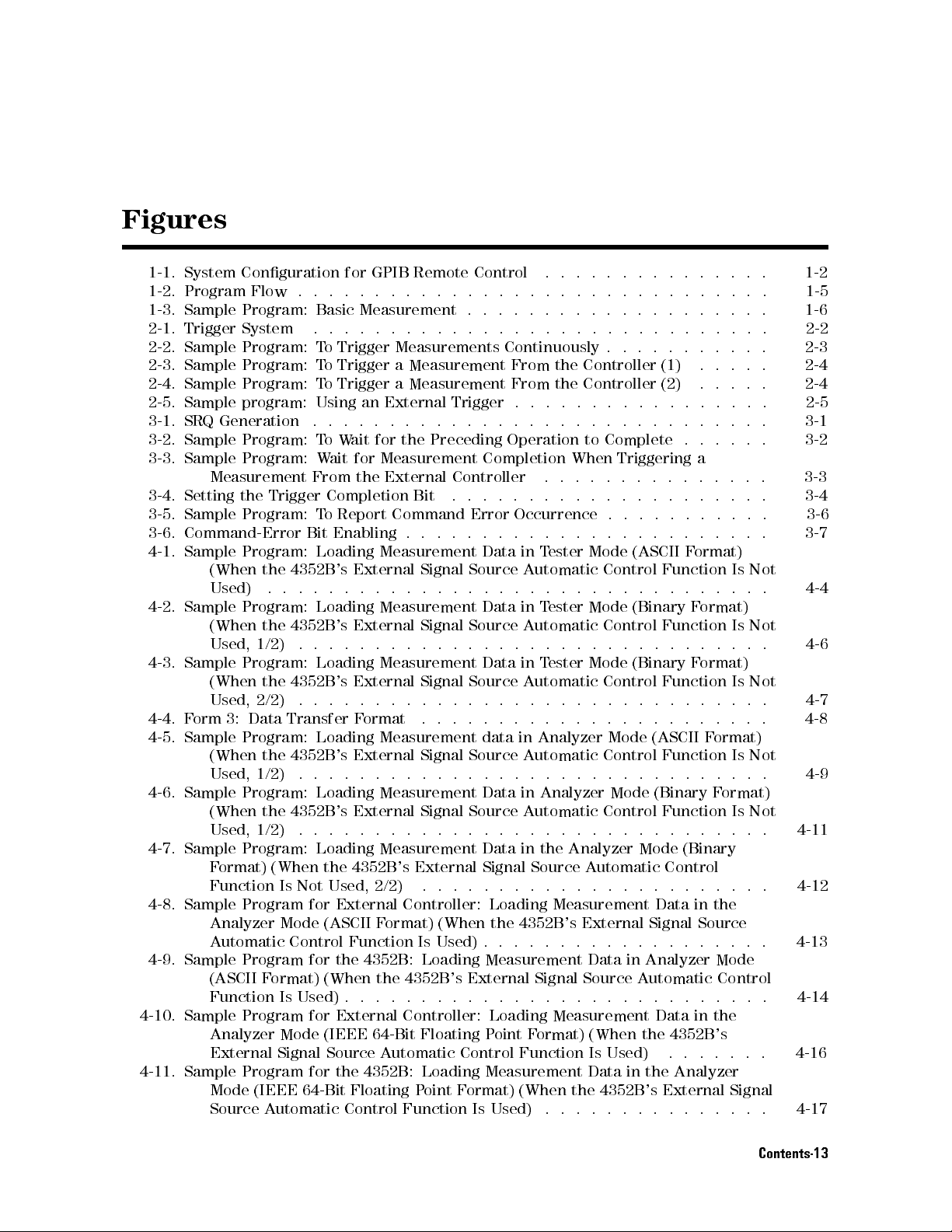
Figures
1-1. System
1-2. Program
1-3. Sample
2-1. Trigger
2-2. Sample
2-3.
Sample
2-4.
Sample
2-5.
Sample
3-1.
SRQ
3-2.
Sample
3-3.
Sample
3-4. Setting
3-5.
Sample
3-6.
Command-Error
4-1.
Sample
4-2.
Sample
4-3.
Sample
4-4.
F
orm
4-5.
Sample
4-6.
Sample Program:
4-7. Sample Program: Loading Measurement Data in the Analyzer Mode (Binary
4-8. Sample Program for External Controller: Loading Measurement
4-9. Sample Program for the 4352B: Loading Measurement Data in Analyzer Mode
4-10. Sample Program for External Controller: Loading Measurement Data in the
4-11. Sample Program for the 4352B: Loading Measurement Data in the Analyzer
Conguration
Flow
Program:
System
Program:
Program:
Program:
program:
Generation
Program:
Program:
Measurement
the
Program:
Program:
(When
Used)
Program:
(When
Used,
Program:
(When
Used,
3:
Data
Program:
(When
Used,
(When
Used,
Format) (When the 4352B's
Function Is Not Used, 2/2)
Analyzer Mode (ASCII F
Automatic Control Function Is Used) . . .
(ASCII F
Function Is Used) . . . . . . . . . . . . . . . . . . . . . . . . . . . . 4-14
Analyzer Mode (IEEE 64-Bit Floating Point Format) (When the 4352B's
External Signal Source Automatic Control Function Is Used) .. ..... 4-16
Mode (IEEE 64-Bit Floating Point Format) (When the 4352B's External Signal
Source Automatic Control Function Is Used) .. ...... ...... . 4-17
.
Trigger
the
4352B
.
.
.
the
4352B
1/2)
.
the
4352B
2/2)
.
Transfer
the 4352B
1/2) .
the 4352B
1/2)
.
ormat) (When the 4352B's External Signal Source A
for
GPIB
Remote
.
.
.
.
.
.
.
.
.
Basic
Measurement
.
.
.
.
.
.
.
.
.
T
o
Trigger
T
o
Trigger
T
o
Trigger
Using
.
.
.
T
o
W
W
ait
From
Completion
T
o
Report
Bit
Enabling
Loading
's
.
.
.
Loading
's
.
.
.
Loading
's
.
.
.
Loading
's External
..
..
Loading Measurement
's External
.
.
.
Measurements
a
Measurement
a
Measurement
an
External
.
.
.
.
.
.
ait
for
the
Preceding
for
Measurement
the
External
Bit
Command
.
.
.
Measurement
External
.
External
.
External
.
F
ormat .
.
Signal
.
.
.
.
.
Measurement
Signal
.
.
.
.
.
Measurement
Signal
.
.
..
..
..
Measurement
Signal Source
..
.
.
.
Signal Source
.
.
.
.
..
External Signal Source A
..
ormat) (When the 4352B
Control
.
.
.
.
.
.
.
.
Trigger
.
.
.
Completion
Controller
.
.
.
Error
.
.
.
Data
Source
.
.
..
Data
Source
.
.
.
Data
Source
.
.
..
data
.
.
.
Data in
.
.
...... ...... ...... ...
.
.
.
.
.
.
.
.
.
.
.
.
.
.
..
..
..
..
.
.
.
.
.
.
.
.
.
.
.
.
.
.
.
..
.
.
.
.
..
..
..
..
.
.
Continuously
From
the
From
the
.
.
.
.
.
.
.
Operation
.
.
.
.
.
.
Occurrence
.
.
.
.
in
T
ester
A
utomatic
.
.
.
in
T
ester
A
utomatic
.
.
..
in
T
ester
A
utomatic
.
.
.
.
..
.
.
in
Analyzer
A
utomatic
.
.
.
.
Analyzer Mode
Automatic
.
.
.
.
................
.
.
.
.
.
.
.
Controller
Controller
.
.
.
.
..
..
to
Complete
When
.
.
.
.
.
.
.
.
.
.
.
.
Mode
Control
.
.
.
.
Mode
Control
.
.
.
.
Mode (Binary
Control Function
.
.
.
.
.
.
.
.
Mode
Control
.
.
.
.
Control Function
.
.
.
.
utomatic Control
's External Signal Source
(1)
(2)
.
.
.
..
.
.
.
.
.
.
Triggering
.
.
.
.
.
.
.
..
..
.
.
.
.
.
.
.
.
..
(ASCII
.
(Binary
.
.
.
.
..
F
ormat)
Function
.
.
.
.
F
Function
.
.
.
.
Format)
.
.
.
.
.
.
.
.
(ASCII F
Function
.
.
..
(Binary
.
.
.
Data in the
utomatic Control
.
.
..
.
.
a
.
.
..
.
ormat)
.
.
.
..
.
.
.
..
.
.
.
.
.
.
.
..
.
.
.
.
.
ormat)
F
ormat)
.
..
.
.
..
.
.
.
.
.
.
.
.
..
.
.
.
.
.
.
. 3-3
..
.
.
.
.
Is
Not
.
.
Is
Not
.
.
Is Not
.
.
.
.
Is
Not
..
Is
Not
.
.
. 1-2
.
1-5
1-6
.
2-2
.
2-3
.
2-4
.
2-4
.
2-5
.
3-1
.
3-2
3-4
.
3-6
.
3-7
.
4-4
.
4-6
.
4-7
.
4-8
. 4-9
.
4-11
4-12
4-13
Contents-13
Page 24
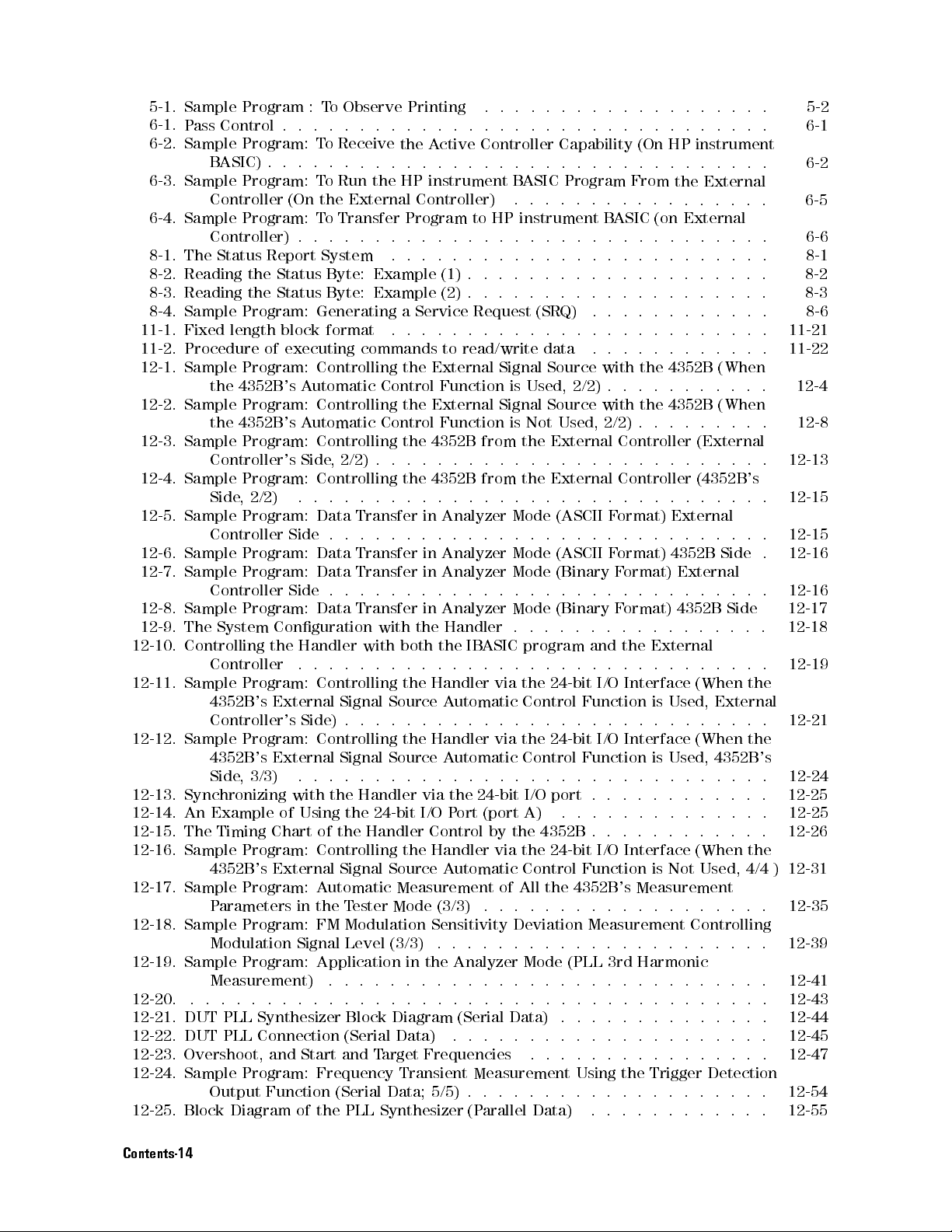
5-1.
Sample Program
6-1.
Pass
Control
6-2.
Sample Program:
B
ASIC) .
6-3.
Sample Program:
Controller
6-4.
Sample
8-1.
The
8-2.
Reading
8-3.
Reading
8-4.
Sample
11-1.
Fixed
11-2.
Procedure
12-1.
Sample
12-2.
Sample
12-3.
Sample
12-4.
Sample
12-5.
Sample
12-6.
Sample
12-7.
Sample
12-8.
Sample
12-9.
The
12-10.
12-11.
12-12.
12-13.
12-14.
12-15.
12-16. Sample Program: Controlling the Handler via the 24-bit I/O
12-17. Sample Program: A
12-18. Sample Program: FM Modulation Sensitivity Deviation Measurement Controlling
12-19. Sample Program: Application in the Analyzer Mode (PLL 3rd Harmonic
12-20. ...................................... 12-43
12-21. DUT PLL Synthesizer Block Diagram (Serial Data) .............. 12-44
12-22. DUT PLL Connection (Serial Data) ..................... 12-45
12-23. Overshoot, and Start and Target Frequencies ................ 12-47
12-24. Sample Program: Frequency Transient Measurement Using the Trigger Detection
12-25. Block Diagram of the PLL Synthesizer (Parallel Data) ............ 12-55
Controlling
Sample Program:
Sample
Synchronizing
An
The
Program:
Controller)
Status
the
the
Program:
length
Program:
the
4352B
Program:
the
4352B
Program:
Controller's
Program:
Side
,
2/2)
Program:
Controller
Program:
Program:
Controller
Program:
System
Controller
4352B
's External
Controller's
Program:
4352B
's
Side
,
3/3)
Example
Timing
4352B's External Signal Source A
Parameters in the T
Modulation Signal Level (3/3)
Measurement) ........................
Output Function (Serial Data; 5/5) . . . . . . . . . . . . . . . . . . . . 12-54
:T
o
.
.
.
.
T
o
Receive
.
.
.
.
T
o
Run
(On the
T
o
Transfer
.
.
.
Report
of
Conguration
the
External
Chart
System
Status
Status
Generating
block
format
executing
Controlling
's
A
utomatic
Controlling
's
A
utomatic
Controlling
Side
Controlling
.
.
Data Transfer
Side
Data Transfer
Data
Side
Data
Handler
..
Controlling
Side)
Controlling
.
.
with
of
Using
of
Byte:
Byte:
,
2/2)
.
.
.
.
Signal
Signal
.
the
the Handler
utomatic Measurement of All the 4352B's Measurement
Observe
.
.
.
.
External
.
.
commands
.
.
..
Transfer
.
.
Transfer
.
.
.
.
.
.
Handler
the
ester Mode (3/3)
.
.
the
.
.
the
HP
Program
.
.
.
Example
Example
a
.
the
Control
the
Control
the
.
.
the
.
..
..
..
with
with
both
.
.
the
Source
.
.
the
Source
.
.
24-bit I/O
Printing
.
.
..
A
.
.
.
instrument
Controller)
.
.
.
.
.
.
Service
.
.
.
External
External
4352B
.
.
.
4352B
..
in Analyzer
.
.
.
in Analyzer
in Analyzer
.
.
.
in
the
the
.
.
.
Handler
.
.
.
Handler
.
.
.
via
Control
...... ...... ...... .
.
.
.
.
.
.
.
.
.
.
..
..
..
..
..
..
..
.
ctive
Controller
..
..
to
HP
.
.
.
..
.
.
.
.
(1)
.
.
.
(2)
.
.
.
Request
.
..
..
to
read/write
Signal
Function
Function
.
..
.
.
Analyzer
Handler
.
A
utomatic
.
A
utomatic
.
the
Port
utomatic Control Function is Not
is
Signal
is
from
.
.
.
from
..
.
.
.
.
.
.
IB
ASIC
.
.
.
via
.
.
.
via
.
.
..
24-bit
(port A)
by
.....
Capability
..
..
B
ASIC
Program
.
.
.
.
instrument
..
..
.
..
..
.
.
.
.
.
.
.
.
(SRQ)
..
..
data
Source
Used,
2/2)
Source
Not
Used,
the
External
.
.
.
..
the
External
.
.
.
.
Mode
(ASCII
.
.
.
.
Mode
(ASCII
Mode
(Binary
.
.
.
.
Mode
(Binary
.
.
.
.
program
.
.
.
.
the
24-bit
Control
.
..
..
the
24-bit
Control
..
..
I/O
port
..
the
4352B
...... ...... ..
..
..
.
.
.
B
ASIC
..
..
..
..
..
..
.
.
.
.
.
.
with
.
with
2/2) .
Controller
.
.
Controller (
.
.
.
F
ormat)
.
.
.
F
ormat)
F
.
.
.
F
.
.
.
and
.
.
.
I/O
Function
..
I/O
Function
..
.
.
..
.
.
(On
..
From
.
.
..
(on
.
.
.
..
.
..
..
..
..
.
.
.
.
.
..
the
.
..
the
..
.
.
.
.
.
.
.
.
.
ormat)
.
.
.
ormat)
.
.
.
the
External
.
.
..
Interface
is
..
.
Interface
is
.
.
.
.
.
.
..
.
.
.
.
Interface (When the
..
..
..
.
.
.
.
.
.
HP
instrument
.
.
.
.
.
.
the
External
..
..
..
External
.
.
.
.
.
.
.
.
.
.
.
.
..
.
.
.
.
..
.
.
.
.
..
..
.
.
.
.
.
.
.
..
..
.
4352B
..
4352B
.
.
External
.
4352B
.
.
Used,
.
Used,
.
.
.
.
(When
..
.
.
(When
.
.
.
.
.
(External
.
.
.
.
.
4352B's
.
.
.
.
.
.
.
.
..
Side
External
.
.
.
.
.
4352B
Side
.
.
.
.
.
..
.
.
.
(When
.
.
(When
.
.
..
.
.
.
..
Used, 4/4 ) 12-31
.....
the
External
.
.
.
the
4352B
.
.
.
..
..
.
.
.
.
.
...
. 5-2
.
6-1
.
6-2
6-5
.
6-6
.
8-1
.
8-2
.
8-3
.
8-6
.
11-21
.
11-22
.
12-4
.
12-8
.
12-13
.
12-15
. 12-15
.
12-16
. 12-16
12-17
.
12-18
.
12-19
.
12-21
's
.
12-24
12-25
.
12-25
.
12-26
12-35
12-39
12-41
Contents-14
Page 25
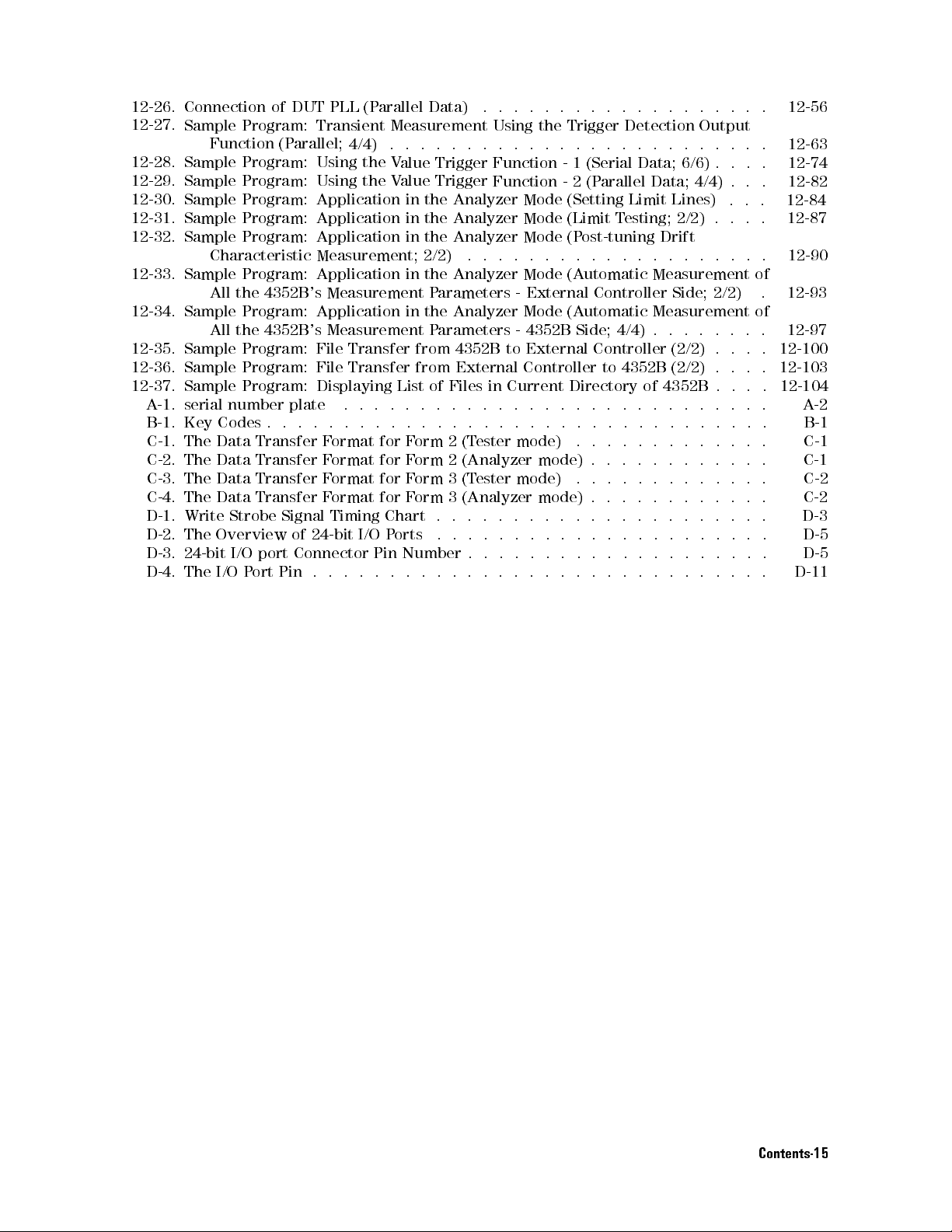
12-26.
12-27.
12-28.
12-29.
12-30.
12-31.
12-32.
12-33.
12-34.
12-35.
12-36.
12-37.
A
-1.
B-1.
C-1.
C-2.
C-3.
C-4.
D-1.
D-2.
D-3.
D-4.
Connection of
Sample Program:
Function
Sample Program:
Sample Program:
Sample Program:
Sample
Sample
Sample
Sample
Sample
Sample
Sample
serial
Key
The
The
The
The
Write
The
24-bit
The
Program:
Program:
Characteristic
Program:
All
the
Program:
All
the
Program:
Program:
Program:
number
Codes
Data
Data
Data
Data
Strobe
Overview
I/O
I/O
P
DUT PLL
(Parallel;
4352B
4352B
plate
.
.
Transfer
Transfer
Transfer
Transfer
Signal Timing
of 24-bit
port Connector
ort
Pin .
(P
Transient
4/4)
Using
the
Using
the
Application
Application
Application
Measurement;
Application
's
Measurement
Application
's
Measurement
File
Transfer
File
Transfer
Displaying
.
.
.
.
.
.
.
F
ormat
F
ormat
F
ormat
F
ormat
I/O P
.
.
.
arallel
.
..
for
for
for
for
Pin Number
.
Data)
Measurement
.
.
.
.
V
alue
Trigger
V
alue
Trigger
in
the
in
the
in
the
2/2)
in
the
P
arameters
in
the
P
arameters
from
from
List
of
.
.
.
.
..
.
F
orm
2
F
orm
2
F
orm
3(T
F
orm
3 (Analyzer
Chart .
orts
.
.
.
.
.
.
Using
.
.
.
Function
Function
Analyzer
Analyzer
Analyzer
.
.
Analyzer
Analyzer
4352B
External
Files
in
..
..
.
.
.
(T
ester
(Analyzer
ester mode)
.
.
.
.
.
.
.
.
.
.
.
.
.
.
.
.
.
Mode
Mode
Mode
.
.
.
Mode
-
External
Mode
-
4352B
to
External
Controller
Current
..
.
.
.
mode)
.
.
.
.
.
.
.
.
.
.
.
.
.
.
.
the
Trigger
..
..
-
1
-
2
(Setting
(Limit
(P
ost-tuning
.
.
.
(A
utomatic
(A
utomatic
Side;
Directory
.
.
.
.
.
.
.
mode)
..
mode) .
.
.
.
.
.
.
.
.
.
.
.
.
.
.
.
..
Detection
..
..
(Serial
(P
Data;
arallel
Limit
T
esting;
.
.
.
..
Controller
4/4) .
Controller
to
4352B
.
.
.
.
.
.
.
.
.
..
.
.
.
.
.
.
.
.
..
..
.
.
.
.
.
.
.
.
.
.
.
.
.
.
.
.
..
..
..
Output
..
..
..
6/6)
..
Data;
4/4) .
Lines)
2/2)
Drift
..
Measurement
Side;
Measurement of
..
(2/2)
(2/2)
of
4352B
.
.
.
.
.
.
..
.
.
.
.
.
.
.
.
.
.
.
..
..
.
.
.
.
.
.
.
.
.
.
.
.
.
.
.
.
.
.
..
.
2/2)
.
.
..
.
.
.
.
.
.
.
.
.
.
.
.
..
..
..
..
.
.
.
.
.
.
.
.
.
.
. 12-56
.
..
..
.
.
..
.
of
.
.
. 12-100
. 12-103
..
12-104
.
.
.
. B-1
.
.
.
.
.
.
.
.
.
.
..
.
.
.
.
12-63
12-74
12-82
12-84
12-87
12-90
12-93
12-97
A
C-1
C-1
C-2
C-2
D-3
D-5
D-5
D-11
-2
Contents-15
Page 26
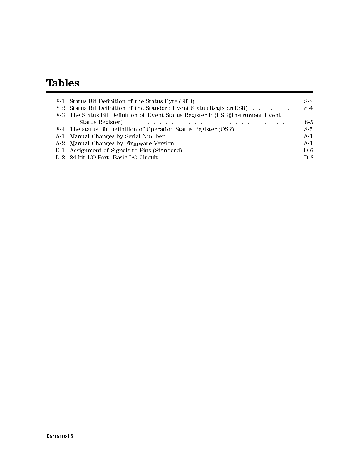
T
ables
8-1. Status
8-2.
Status
8-3.
The
Status
8-4.
The
A
-1.
Manual
A
-2.
Manual
D-1.
Assignment
D-2.
24-bit
Bit Denition
Bit
Denition
Status
Bit
Register)
status
Bit
Changes
Changes
of
I/O
P
ort,
of
of
Denition
.
Denition
by
Serial
by
Firmware
Signals
Basic
to
I/O
the
the
of
.
.
of
Number
Pins
Circuit
Status
Standard
Byte
Event
.
.
.
.
Status
Operation
V
ersion
(Standard)
.
(STB)
Event
.
.
Status
.
.
.
.
.
Status
Register
.
.
.
Register
.
.
.
.
.
.
.
.
.
.
.
.
.
.
.
.
Register(ESR)
B
(ESB)(Instrument
.
.
.
..
.
.
.
.
.
.
.
.
.
.
.
.
.
.
.
.
.
.
..
.
.
..
.
.
.
.
.
..
..
.
.
..
.
.
..
..
..
.
.
.
.
.
.
..
.
.
..
..
..
.
.
.
..
.
.
Event
.
.
.
.
..
..
.
.
.
.
.
.
.
.
.
.
..
.
.
.
.
.
.
.
.
.
.
.
.
.
.
8-2
8-4
8-5
8-5
A
-1
A
-1
D-6
D-8
Contents-16
Page 27

1
Overview
This chapter
basic use
of
the
provides
GPIB
GPIB commands
What
is
GPIB?
Required
1.
The
4352B
2.
F
or
the
Equipment
and
GPIB
Using
of GPIB
information
commands
are
used.
its
accessories
system
controller
HP
instrument
.
F
or
detailed
The
control
standard
peripherals
IEEE
interface
computer
and
Remote Control
on
how
to
In
most
General
of
488.1
receives
required
B
ASIC,
congure
of
the
sample
information
Purpose
the
4352B
for
interfacing
.
This
standard
,
IEC-625
allows
.
The
data
to
the
the
computer
from
test
4352B
about
Interface
V
CO/PLL
,
IEEE
4352B
a
specic
can
the
programs
each
instruments
supports
488.2
to
sends
the
instrument through
be
GPIB
remote-control
command,
Bus
(
Signal
,
and
be
controlled
commands
device
used
as
System
shown
in
this
see
GPIB
)
is
used
Analyzer
to
worldwide
.
computers
standards
JIS-C1901
by
an
or
instructions
under
the
test
(
system
dut
system
manual,
chapters
for
remote
GPIB
is a
and
.
The
GPIB
external
the GPIB
).
controller
and
simple
9
to
to
.
.
the
11.
Or
,
An
HP 9000
co-processor
memory
space
.
Series 200
or card
to hold
(HP
BASIC,
or 300
computer
82300 or
82324 ).
needed binaries
or
an
The
,and
HP
V
computer
at
least
ectra
64
PC
with
must
kilobytes
a
measurement
have
enough
of
program
BASIC 3.0 or higher operating system and the following binary extensions:
HPIB, GRAPH, IO
A disk drive is required to load B
(Depending on the disk drive
, KBD
, and ERR
ASIC, if no internal disk drive is available
, a binary
such as CS80 may be required.)
.
3. External Signal Source
4. Peripherals (printer, plotter, and so on) and any GPIB instruments that are required for your
application.
5. 10833A/B/C/D GPIB cables to interconnect the computer, the 4352B, and any peripherals.
Overview of GPIB Remote Control System 1-1
Page 28
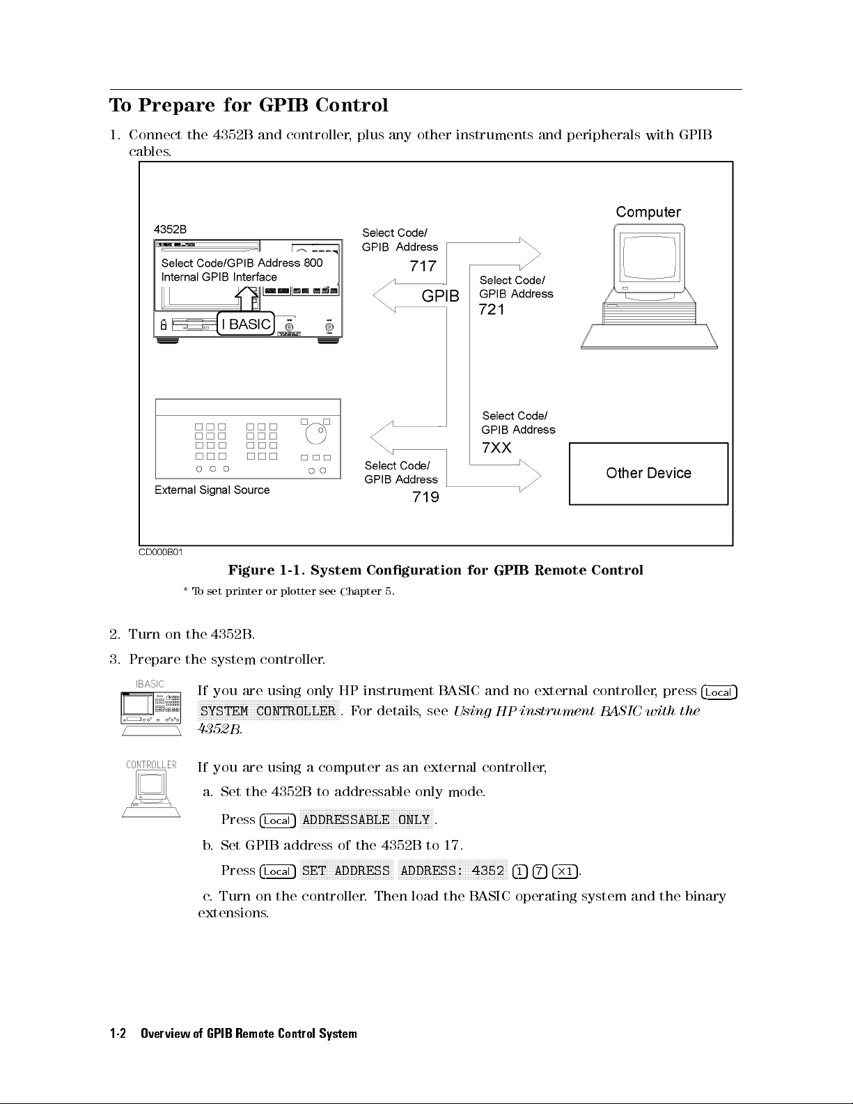
To
Prepare for
1.
Connect
cables
.
the
4352B
GPIB Control
and
controller
,
plus
any
other
instruments
and peripherals
with GPIB
2.
Turn
3.
Prepare
Figure
*
T
o
set
printer
on
the
4352B
the
system
If
you
NN
NN
N
N
N
N
N
N
N
N
N
N
N
SYSTEM
4352B
If you are using a computer as an external controller
a. Set
Press
1-1.
or
plotter
System
see
Conguration
Chapter
5.
.
controller
are
using
N
N
N
N
N
N
N
NN
NN
NN
NN
N
CONTROLLER
.
only
HP
N
N
N
N
N
N
N
N
N
N
N
N
N
N
N
N
NN
NN
NN
.
instrument
F
or
details
B
ASIC
,
see
Using
.
the 4352B to addressable only mode
NNNNNNNNNNNNNNNNNNNNNN
5
ADDRESSABLE ONLY
4
Local
NNNNNNNNNNNNNNNNNNNNNNNNN
NNN
.
for
GPIB
and
HP
.
Remote
no
external
instrument
,
Control
controller,
B
ASIC
b. Set GPIB address of the 4352B to 17.
Press
4
Local
5
NNNNNNN
NNNNNNNNNNNNNNNNNNNNNNNNN
SET ADDRESS
NNNNNNN
NNNNNNNNNNNNNNNNNNNNNNNNN
NNN
ADDRESS: 4352
NNNNNNNNN
4
1547542
5
.
1
c. Turn on the controller. Then load the BASIC operating system and the binary
extensions.
press
with
the
5
4
Lo
cal
1-2 Overview of GPIB Remote Control System
Page 29
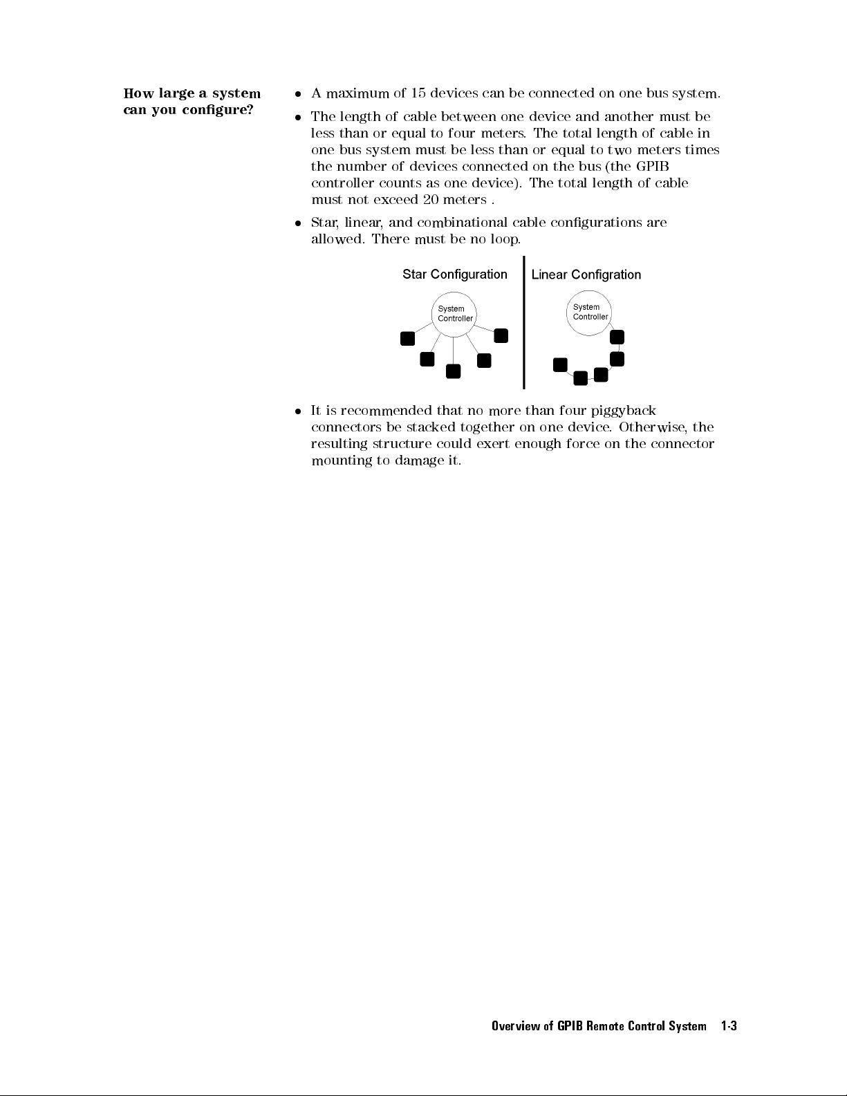
How large
can you
congure?
a system
A
maximum of
The length
less
one
the
number of
controller
must
Star
,
allowed.
It is
connectors
resulting
mounting
15 devices
of cable
than or
equal to
bus system
between one
four meters
must be
devices connected
not
linear
counts as
exceed
,
and
There
one device).
20 meters
combinational
must
recommended that
be stacked
structure could
to damage
can
less than
.
be
no
loop
no
more
together on
exert enough
it.
be
connected
device and
.The
or equal
on the
The total
cable
.
than
one
on
one
bus
another must
total length
to two
bus (the
length of
of cable
meters times
GPIB
cable
congurations are
four
piggyback
device
.
Otherwise
force on
the
connector
system.
be
in
,
the
Overview of GPIB Remote Control System 1-3
Page 30
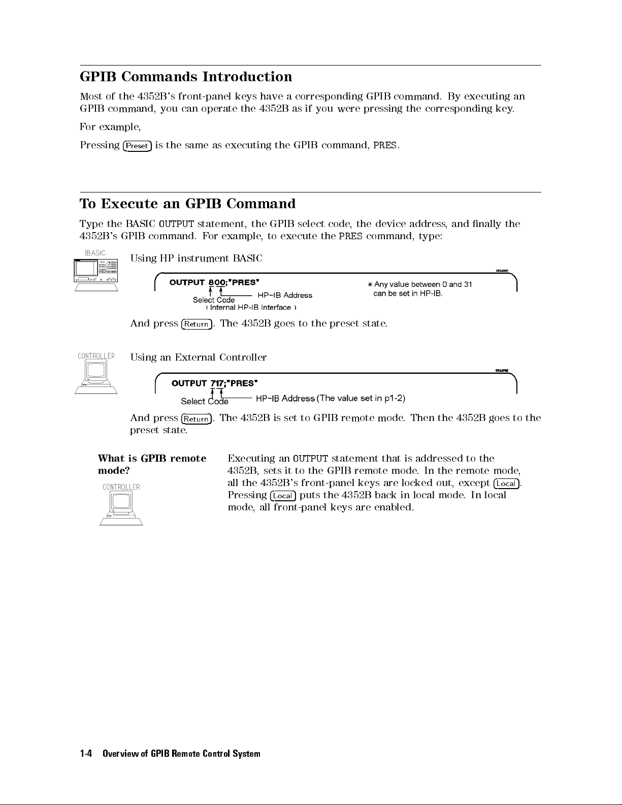
GPIB Commands
Most
of
the
4352B
's front-panel
GPIB
F
or
command,
example
you
can
,
Introduction
keys have
operate the
4352B as
a corresponding
if you
were pressing
GPIB command.
the corresponding
By executing
key.
an
Pressing
T
o
Execute
Type the
4352B's
5
4
Preset
BASIC
is
the
an
OUTPUT
same
GPIB
GPIB command.
Using
HP
instrument
And
press
4
Return
Using
an
External
And
press
4
Return
preset
state
.
as executing
Command
statement,
F
or
example
B
ASIC
5
.
The
Controller
5
.
The
the GPIB
the
GPIB
,
to
execute
4352B goes
4352B
is
set
select
to the
to
GPIB
command,
code
,
the
the
PRES
preset state
remote
PRES
.
device
command,
.
mode
.
address
type:
Then
,
the
and
4352B
nally
goes
the
to
the
What
mode?
is
GPIB
remote
Executing
4352B
,
sets
all
the
4352B
Pressing
mode
,
all
an
OUTPUT
it
to
the
's
front-panel
5
4
puts
Lo
cal
front-panel
statement
GPIB
the
4352B
keys
remote
keys
back
are
enabled.
that
mode
are
is
addressed
.
In
locked
in
local
the
out,
mode
to
the
remote
except
.
In
mode
4
Lo
local
cal
,
5
.
1-4 Overview of GPIB Remote Control System
Page 31

To
Program a
This
section
shows
a
typical
describes
program
Basic Measurement
how
to organize
ow for
the commands
a measurement.
into a
measurement sequence
. Figure
1-2
The
following
program
This
use
the
to
7
and
manual
sample
change
performs
shows
programs
the
Figure
the
measurement
program
on
GPIB
address
1-2.
lists
an
external
Program
ow
of
sample
from
Flow
controlling
programs
controller
00
to 17
the
for
,
change the
(that is
4352B
using
HP instrument
select code
,
use
717
instead
GPIB
BASIC.
from
of
.
800).
T
o
8
Overview of GPIB Remote Control System 1-5
Page 32

d a
100
110
120
130
140
150
160
170
180
190
200 INPUT
210 INPUT
220
230
240
250
260 OUTPUT
270
280
290
300
310
320
330
340
350
360
370
!
File
Name
: FIG1_3.TXT
!
IBASIC
MEASUREMENT
!
ASSIGN
@Hp4352
TO
800 !
!
!
OUTPUT
OUTPUT
OUTPUT
@Hp4352;"PRES"
@Hp4352;"HOLD"
@Hp4352;"VT"
!
"DC POWER
"DC CONTROL
VOLTAGE (V)",Dc_power
VOLTAGE (V)",Dc_ctrl
!
OUTPUT
OUTPUT
OUTPUT
@Hp4352;"VPOW ";Dc_power
@Hp4352;"VCTRL ";Dc_ctrl
@Hp4352;"VOUT ON"
@Hp4352;"MEAS POWE"
!
DISP
"CONNECT
DEVICE
PAUSE
DISP
!
EXECUTE
"SING"
Power_data=READIO(8,0)
!
PRINT
"POWER
";Power_data;"
!
END
SAMPLE PROGRAM
IBASIC address
!
Preset 4352
!
Trigger HOLD
!
Select Tester
!
Select
and
PRESS
!
Measure
CONTINUE."
(dBm)"
! Set
! Set
DC Power
DC Control
! Supply
Power
Power
mode
DC voltages
Level
Level
Voltage
Voltage
Measurement
c b
Figure
1-3.
Sample
Program:
Basic
Measurement
1-6 Overview of GPIB Remote Control System
Page 33

Set
I/O
P
ath
130
When
an
external
Set
Up
the
160 OUTPUT
170 OUTPUT
180
190
200
210
220
230
240
250
260
You
can execute
for
example
N
N
NN
NN
NN
NN
N
N
N
N
N
N
N
N
N
N
N
N
N
N
N
INST TYPE:
4
Meas
Generally
that
DC
control
GPIB
of
setup
N
NN
N
N
N
N
N
N
N
N
N
RF
POWER
5
,
of
the
Command
.
Now
ASSIGN
OUTPUT
!
INPUT
INPUT
!
OUTPUT
OUTPUT
OUTPUT
OUTPUT
,
N
NN
NN
NN
N
N
N
N
N
N
the
front
voltage),
@Hp4352
controller
Measurement
@Hp4352;"PRES" !
@Hp4352;"HOLD" !
@Hp4352;"VT"
"DC
"DC
@Hp4352;"VPOW
@Hp4352;"VCTRL
@Hp4352;"VOUT
@Hp4352;"MEAS
GPIB
works
N
N
in the
NN
N
N
N
N
N
N
N
N
N
N
N
N
N
N
N
N
N
NN
N
.
panel
with
NN
you
a
can
VCO TESTER
N
N
N
N
NN
procedure
you
TO
is
used,
POWER
CONTROL
commands
NN
NN
key
P
measure
VOLTAGE
same manner
N
N
N
N
N
.Also
to
setup
operations
need
to
arameter"
800
!
IBASIC
change
P
arameters
Preset
Trigger
!
Select
(V)",Dc_power
VOLTAGE
";Dc_power
";Dc_ctrl
ON"
POWE"
in
the
same
as the
,
line
260
works
measurement
.
In
lines
specify
the
for
device
parameters
the
address
\800"
!
parameters
.
to
4352
HOLD
Tester
!
!
!
Select
sequence
key
operations
in
the
conditions
230
and
\717".
Set
DC
Set
DC
Supply
Power
as
same
240 (setups
for
GPIB
of
mode
Power
Control
DC
key
manner
using
the
GPIB
Voltage
voltages
Level
4
commands
Measurement
operation.
N
N
N
N
N
N
INST
5
Meas
as
the
instrument is
of
commands
Voltage
Line
N
N
NN
NN
NN
N
N
N
N
N
N
N
N
N
TYPE
the
key
DC
power
.
See \T
180,
N
N
N
N
N
N
and
operations
identical to
voltage
o
Execute
. This
and
an
is
the
end
Connecting
280
Line
280
Trigger
320 EXECUTE
Line 320
Transfer Data
330 Power_data=READIO(8,0)
The measurement data is transferred to IB
and the 4352B V
Handbook.
Note
a
Device
DISP
"CONNECT
prompts
a
executes
the
Measurement
"SING"
a
single
CO/PLL Signal Analyzer Manual Supplement
If you are going to run the program on an external controller, you must make
some modications. See the program described in Chapter 4.
DEVICE
operator
trigger
to
connect
.
and
See
Chapter
PRESS
a
device
Single
ASIC. F
CONTINUE."
.
Trigger
2
for
the
details of
or details about data transfer
trigger
for HP instrument B
control.
, see Chapter 4
ASIC Users
Overview of GPIB Remote Control System 1-7
Page 34

To
Execute an
Some
GPIB
commands
GPIB Command
require
a numeric
parameter.
with a
For
Parameter
example:
(The
to
240,
OUTPUT
space
@Hp4352;"VPOW
between
you
enter
4.0"
the
command and
the parameters
Set
DC power
the numeric
and execute
voltage to
parameter is
the GPIB
4[V]
.
mandatory.)
commands every
time
In lines
you
run
200
the
program.
200
210
220
230 OUTPUT
240
T
o
set the
number
INPUT
INPUT
!
OUTPUT
DC power
as
follows after
"DC
"DC
POWER
CONTROL
VOLTAGE (V)",Dc_power
VOLTAGE (V)",Dc_ctrl
@Hp4352;"VPOW ";Dc_power
@Hp4352;"VCTRL ";Dc_ctrl
voltage to
each message
4.0
[V]
and
is displayed.
the
!Set
!Set
DC
control
DC Power
DC Control
voltage
to
Voltage
Voltage
2.5
[V],
enter
each
d a
DC
POWER
4
4
x1
DC CONTROL
2.5
Query
Most
GPIB
command.
command
VOLTAGE
5
VOLTAGE
4x15
Commands
commands
F
or
example
as
follows
(V)
(V)
that
are
used
with
a
,
when
the
VPOW
numeric
command
parameter
is
combined
can
with
also
a
?
be
,
it
used
is used
as
a
as
query
a
query
,
10
20
30
If
you
result
OUTPUT
ENTER
PRINT
execute
of
this
@Hp4352;"VPOW?"
@Hp4352;A
A
the
VPOW?
program
command,
will
be
as
the
follows
instrument returns
.
the current
DC power
voltage.
The
d a
4.0
Using a Query command enables you to match the
setup values
.
program variables with the 4352B's current
1-8 Overview of GPIB Remote Control System
Page 35

2
Triggering
This chapter
Note
describes
Frequency
trigger
Chapter
T
o
trigger a
Set
GPIB
(Because
are
Set
(Hold),
Generate
The
4352B
measurement from
the
,
or
trigger
Free
source
Run
neither
not
mentioned
the
trigger
Single
the
mode
or
trigger
trigger
4352B
how
Transient
function
12
to:
(Internal)
External
in
this
to:
Continuous
event
system
has
to
control
available
for
details
a controller
or
Manual
manual.)
and
the
three
the
trigger
Measurements
with
the
.
,
the
is
valid
for
4352B
states: Idle
starts
,
system
can
4352B
following
triggering
a
measurement.
W
aiting
of
be
.
steps
for
the
also
See
from
Trigger
4352B
triggered
V
are
.
using the
alue Trigger
commonly
the
controller
,
and
Measurement.
value
Function
used:
,
these
in
sources
Triggering 4352B 2-1
Page 36
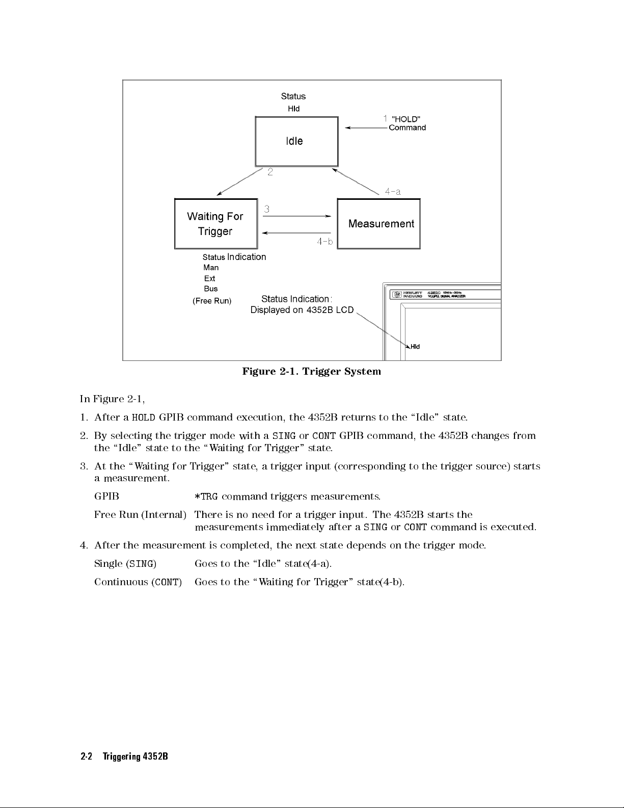
In
Figure
1.
After
2.
By
selecting
the
\Idle"
3.
At
the
a
measurement.
2-1
a
\W
,
HOLD
state
aiting
GPIB
the
command
trigger
to
the
for
Trigger"
mode
\W
execution,
with
aiting
state
Figure
a
for
Trigger"
,
a
2-1.
the
SING
trigger
Trigger
4352B
or
CONT
state
input
System
returns
GPIB
to
command,
.
(corresponding
the
\Idle"
the
to
the trigger
state
4352B
.
changes
source) starts
from
GPIB
Free
Run
(Internal)
4.
After
the
measurement
Single (
Continuous (
SING
) Goes to the \Idle" state(4-a).
CONT
2-2 Triggering 4352B
*TRG
command
There
is
no
need
measurements
is
completed,
) Goes to the \W
triggers
for
immediately
the
measurements
a trigger
input. The
after
next
state
a
SING
depends
.
4352B starts
or
on the
aiting for Trigger" state(4-b).
CONT
command
trigger
the
is executed.
mode
.
Page 37
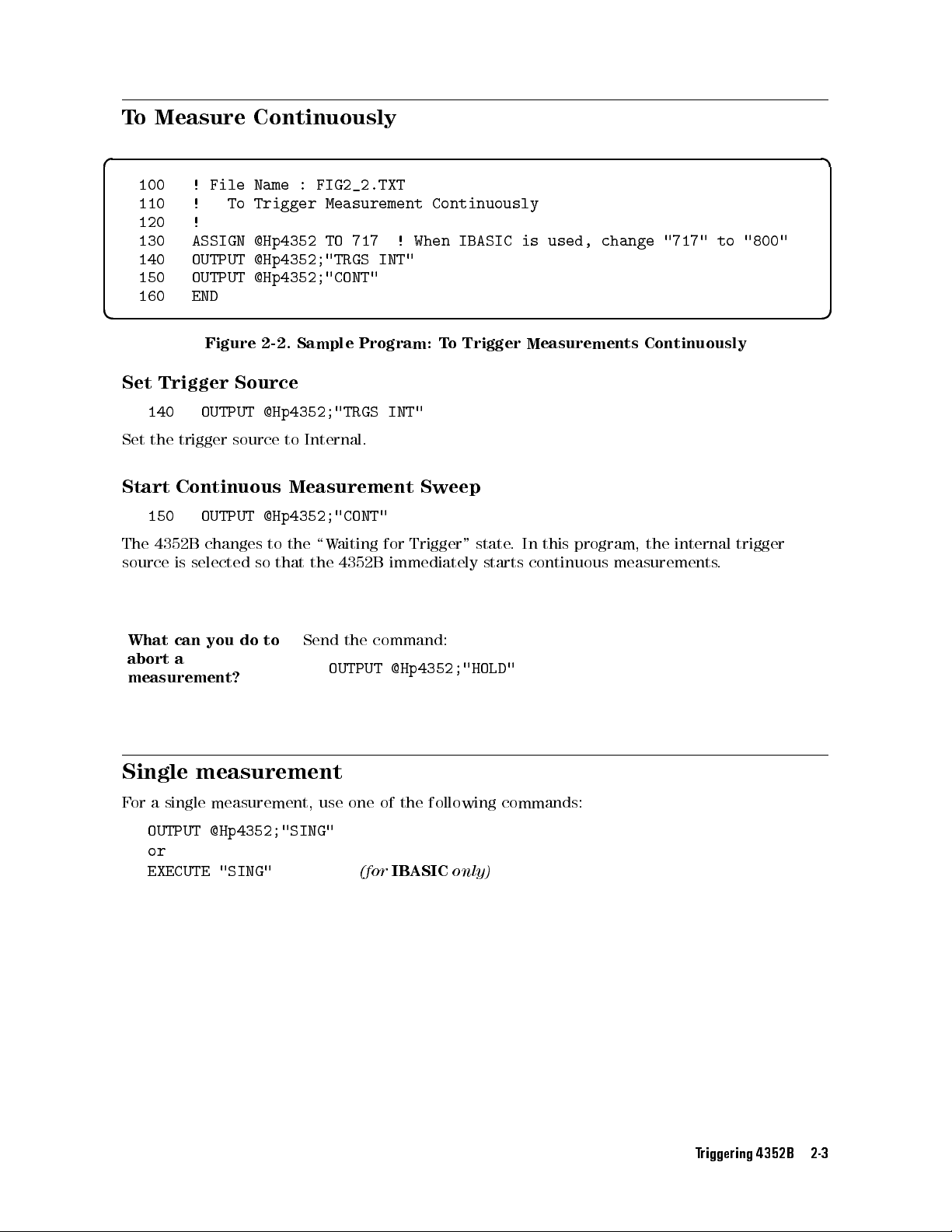
To
Measure Continuously
d a
100 !
110 !
120
130
140
150 OUTPUT
File Name
To Trigger
!
ASSIGN
OUTPUT
: FIG2_2.TXT
Measurement Continuously
@Hp4352
TO
717 !
@Hp4352;"TRGS
@Hp4352;"CONT"
When IBASIC
INT"
is used,
change "717"
to
"800"
160 END
c b
Set
Trigger
140
Set
the
Start
150
The
4352B
source
Figure
OUTPUT
trigger
Continuous Measurement
OUTPUT
changes
is
selected
2-2.
Sample
Source
@Hp4352;"TRGS
source
to
Internal.
@Hp4352;"CONT"
to
the
so
that
the 4352B
\W
Program:
aiting
T
o
INT"
Sweep
for
Trigger"
immediately
Trigger
state
starts
Measurements
.
In this
program, the
continuous
Continuously
internal
measurements
trigger
.
What
can
you
abort
a
measurement?
Single
F
or
OUTPUT
measurement
a
single
measurement,
@Hp4352;"SING"
or
EXECUTE "SING"
do
to
Send
use
the
OUTPUT
one
(for
command:
@Hp4352;"HOLD"
of
the
following
IBASIC
only)
commands:
Triggering 4352B 2-3
Page 38
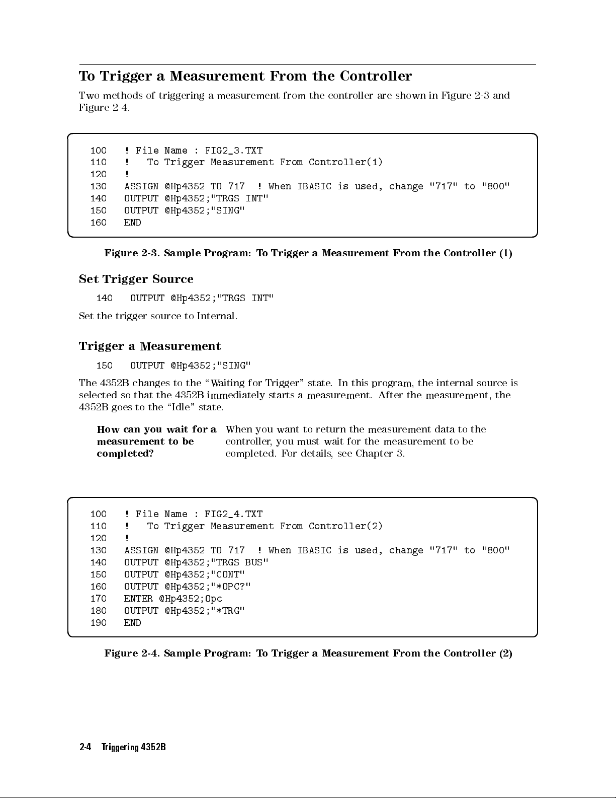
To
Trigger a
Two
methods
Figure
2-4
.
Measurement From
of
triggering
a measurement
the Controller
from the
controller are
shown in
Figure 2-3
and
d a
100
110
120
130
140
150
160
!
File
!
To
!
ASSIGN
OUTPUT
OUTPUT
END
Name
:
FIG2_3.TXT
Trigger
@Hp4352
Measurement
TO
717
@Hp4352;"TRGS
@Hp4352;"SING"
!
INT"
From
When
Controller(1)
IBASIC
is used,
change "717"
to "800"
c b
Figure
Set
Trigger
140
Set
the
Trigger
150
The
4352B
selected
4352B
How
measurement
completed?
2-3.
Source
OUTPUT
trigger
source
a
Measurement
OUTPUT
changes
so
that
the
goes
to
the
can
you
Sample
Program:
@Hp4352;"TRGS
to
Internal.
@Hp4352;"SING"
to
the
\W
aiting
4352B
\Idle"
wait
to
state
for
be
immediately
.
When
a
controller
completed.
T
INT"
for
you
o
Trigger
Trigger"
starts
want
,
you
F
or
a
Measurement
state
.
In
a
measurement.
to
return
must
wait
details
,
see
From
this program,
After
the
measurement
for
the
measurement
Chapter
3.
the
Controller
the
internal
the
measurement,
data
to
to
be
source
the
(1)
is
the
d a
100
110 !
120
130 ASSIGN @Hp4352
!
!
File
To
Name
:
Trigger
FIG2_4.TXT
Measurement
TO 717
From
Controller(2)
! When IBASIC is used, change "717" to "800"
140 OUTPUT @Hp4352;"TRGS BUS"
150 OUTPUT @Hp4352;"CONT"
160 OUTPUT @Hp4352;"*OPC?"
170 ENTER @Hp4352;Opc
180 OUTPUT @Hp4352;"*TRG"
190 END
c b
Figure 2-4. Sample Program: To Trigger a Measurement From the Controller (2)
2-4 Triggering 4352B
Page 39

Set
Trigger
Source
140
Set
the
Trigger
180
Triggers
Using an
OUTPUT @Hp4352;"TRGS
trigger
source
to
GPIB
a Measurement
OUTPUT
the
4352B
@Hp4352;"*TRG"
.
External Trigger
BUS"
.
d a
100
!
File
Name
:
FIG2_5.TXT
110
!
To
120
130
140
150
160
170
180
!
ASSIGN
OUTPUT
OUTPUT
OUTPUT
!
END
Trigger
@Hp4352
@Hp4352;"TRGS
@Hp4352;"TRGP
@Hp4352;"CONT"
Measurement
TO
717
!
When
EXT"
POS"
with
IBASIC
External
is
Trigger
used,
change
"717"
to
"800"
c b
Figure
Selecting
140
Selects the
Measurement
160
Allows
selected
Trigger
OUTPUT
external
OUTPUT
the 4352B
in
this
program,
Source
@Hp4352;"TRGS
trigger
Trigger
@Hp4352;"CONT"
to assume
trigger input terminal. Y
trigger source
.
2-5.
Sample
program:
Using
EXT"
source
.
the trigger
continuous
wait state
. Because
measurement starts
ou can use an external device
an
External Trigger
the external
upon
input
trigger source
of
a
pulse
to
the
is
external
such as controller or foot switch as a
Triggering 4352B 2-5
Page 40

Page 41

3
Synchronizing
You
can
control
communicate with
and the
For
4352B
example
to transfer
wait
until
the
4352B
a
handler
.
,
The
program
measurement
the
communication
data.
measurement.
The
following
Use
the
Y
ou
can
Generate SRQ
The
4352B
byte
consists
the
4352B
two
*OPC?
verify
has
.
F
techniques
command.
the
execution
with
a
status
of
an
8-bit
or
details
the
about
manual.
What
is
an
SRQ?
the Controller
from
an
via
GPIB
on
the
Also
with
are
completion
4352B
's
reporting
register
the
An
SRQ
controller
to
report
can
be
such
as
external
.
controller
,
when
the
available
status
system
where
status
(Service
.
It
the
synchronized
sweep
controller
T
o
do
this
must
it
controls
handler
is
to
synchronize
of
the
report
to
report
each
bit
byte
register
Request)
is
generated
occurrence
with
end,
occurs
function.
with 4352B
to
,
it
is
necessary
wait
until
the
completed
preceding
the
represents
bit
is
an
when
of
a
specic
the
controller
.
read
measurement
after
handler
before
the
controller
commands
status
of
a
specic
assignment,
interrupt
a
bit
of
event.
to
synchronize
the
measurement
via
the
4352B
performing
and
by
instrument.
status
see Chapter
from
the
the
status
Therefore
when a
data
and
the
controller
ends
,
it
must
the
next
the
4352B
using
this
command.
The
status
condition
8in
4352B to
byte
is
the
the
set
4352B
specic event,
:
of
this
to 1
Figure 3-1. SRQ Generation
Synchronizing the Controller with 4352B 3-1
Page 42

To
Wait
For
the Preceding
Operation to
Complete
d a
100
110
120
130
140
150
160
170
180
190
200
210
220
! File
! To
Name
Wait
:
for
!
ASSIGN @Hp4352
!
!
OUTPUT
statement
!
OUTPUT
ENTER
@Hp4352;"*OPC?"
@Hp4352;A
!
!
Next
operation
!
END
FIG3_2.TXT
the
Preceding
TO
800
to
!
send
!
Operation
IBASIC
GPIB
Wait
address
command
until
Complete
Operation
Completed
c b
Figure
Let
Controller
170
180
In
line
180,
*OPC?
Y
as
command
ou
cannot
synchronizing
3-2.
OUTPUT
ENTER
the
controller
use
*OPC?
Sample
W
ait
Program:
F
or
Operation
@Hp4352;"*OPC?"
@Hp4352;A
waits
are
completed,
for
the
functions
the
program
and
T
o
W
!
for
the next
and
then
listed
measurement
ait
for
the
to
Complete
Wait
until
execution until
returns
1
.
under
end.
Preceding
Operation
SRQ
(at
Use
the
(OPC)
the
operations
the
beginning
status
Operation
Completed
of the
byte
for
to
Complete
preceding
chapter)
this
purpose
the
such
.
3-2 Synchronizing the Controller with 4352B
Page 43

Waiting
Measurement
The
following program
for Measurement
From the
External
assumes the
Completion When
Controller
trigger is
being held.
Triggering a
d a
100
110
120
130
140
150
160
170
180
190
200
210
220
230
240
250 Measuring:GOTO
260
270
280
290
! File
! To
Name :
Wait for
FIG3_3.TXT
Sweep End
!
ASSIGN @Hp4352
TO 717
CLEAR @Hp4352
OUTPUT @Hp4352;"TRGS
OUTPUT @Hp4352;"CLES"
OUTPUT @Hp4352;"*SRE
OUTPUT @Hp4352;"*OPC?"
ENTER @Hp4352;Opc
!
ON
INTR 7
ENABLE
INTR
GOTO
7;2
Sweep_end
!
OUTPUT
@Hp4352;"SING"
Measuring !
Sweep_end:
!
!
DISP
"MEASUREMENT
END
INT" !
4;ESNB 1"
COMPLETE"
Using External
! 4352
! Clear
! Wait
Wait for
Set
Address
trigger
Status
until
interrupt of
Controller
to
internal
Registers
operation
completed
Sweep
End
c b
W
ait
for
Measurement
Completion
Figure
Sample
When
3-3.
Program:
Triggering
a
Measurement
Controller
Enabling
160
170
Line
160 clears
command
the
Status
the
Measurement
OUTPUT @Hp4352;"CLES"
OUTPUT @Hp4352;"*SRE
*SRE 4
Byte
all bits
Register).
of
sets the
the
Status
Service Request
The
command
Completion
!
Clear
4;ESNB
Registers
1"
and
Enable Register
ESNB
1
Bit
the
sets
Status
Enable
the
Event
Registers
Registers
to
00000100
Status Enable
0000000000000001 (this enables bit 0 of the Event Status Register B
.
(this
From
In
line
170,
enables
the
Register
. See Figure 3-4).
External
the
bit
2
of
B
to
Synchronizing the Controller with 4352B 3-3
Page 44

The
enable
completion is
register
reported
Register(SRE) and
the
single trigger
Register
of
time
generated.
Chapter
B)
the
Event Status
,
bit 2
8
is generated.
of the
When
for
additional
Figure
is
used
to
as
follows:
bit
0
of
the
measurement
Because
Register
Service
an
SRQ
B
Request
is
generated,
information).
3-4.
Setting
specify an
Line
Event
,
Status
is
completed,
bit
0
which
is
Enable
the
event that
170
sets
Enable
a
of
the
ESNB
bit
2
of
Register
bit
6
of
Trigger
bit
Completion
will
generate
2
of
the
Register
corresponding
has
already
the
the
Status
(SRE)
Status
Byte
has
Byte
an
Service
B
(ESNB),
event
been
Register
also
been
Register
Bit
SRQ.
The
Request
respectively
(bit
0
of
set
to
is
be
set
to
is
also
measurement
Enable
,
to
the
Event
1,
the
summary
set
to
1.
1,
and
an
set
to
1
1.
When
Status
At
SRQ
(see
bit
this
is
Enable
SRQ Interrupt
210
220
.
.
.
260
ON
ENABLE
Sweep_end:
INTR
7
INTR
GOTO
7;2
Sweep_end
Line 210 denes a branch. When the SRQ interrupt is generated from the GPIB interface
(whose select code is 7), the controller goes to the label
Sweep_end
(Line 260).
Line 220 enables an interrupt from interface 7 (GPIB) when bit 1 (SRQ bit) of the interrupt
register of the controller is set by a value of 2.
3-4 Synchronizing the Controller with 4352B
Page 45

W
The
ait
250
Until
Measurement
Measuring:GOTO Measuring
controller
continues
to
loop
Is
on
Done
this
!
line
Wait
until
for
interrupt
an
SRQ interrupt
of
Sweep
is generated.
End
Generate
On
a single
Status
Once
Byte Register
250
Measuring:GOTO Measuring
260
Sweep_end:
an
SRQ
SRQ
trigger end,
is also
is
generated,
bit 0
!
of the
set to
the
SRQ
Event
1, an
interrupt
Status
SRQ
is
Loop until
At
Register
generated.
SRQ
interrupt,
is
disabled.
B
is
set
to
SRQ interrupt
jump
to
1,
and
here
because
bit
2
of
the
Synchronizing the Controller with 4352B 3-5
Page 46

To
Report Command
Error Occurrence
d a
100
110
120
130
140
150
160
170
180
190
200
210
220
230
240
250
260
270
280
290
300
310
320
330
340
350
360
370
380
!
File
Name
:
!
To
Report
!
ASSIGN
@Hp4352
!
DIM
Err$[30]
OUTPUT
OUTPUT
ON
ENABLE
@Hp4352;"CLES"
@Hp4352;"*SRE
INTR
8
GOSUB Err_report
INTR
8;2
!
!
OUTPUT
statement
!
!
!
GOTO
Prog_end
Err_report: !
OUTPUT
ENTER
PRINT
PRINT
@Hp4352;"OUTPERRO?"
@Hp4352;Err,Err$
"COMMAND
Err,Err$
!
A=SPOLL(@Hp4352)
OUTPUT
ENTER
ENABLE
@Hp4352;"*ESR?"
@Hp4352;Estat
INTR
8
RETURN
Prog_end:
!
END
FIG3_5.TXT
Command Error
TO
800
!
IBASIC
32
;*ESE 32"
to
send
ERROR
DETECTED"
!
When
Occurrence
address
!
Clear
! When
!
When
GPIB command
!
Get
!
Save
!
Print
!
Read
Computer
status
registers
Computer is
Computer is
error
is
error
error
status
used,
message
NO.
NO.
register
change
used, change
used, change
and
message
and
message
"8"
to
"8"
"8" to
"7"
to
"7"
"7"
c b
F
or details
on SRQ
Measurement
Figure
3-5.
interrupt, see
From
the
Sample
External
Program:
the
\W
aiting
Controller"
T
o
Report
for
example
Command
Measurement
.
Completion
Enable Error Bit
160 OUTPUT @Hp4352;"CLES"
! Clear status registers
170 OUTPUT @Hp4352;"*SRE 32 ;*ESE 32"
Line 160 clears all bits of the Status Registers and Enable Registers
In line 170, the
enables bit 5 of
Register to 00100000 (this enables
*SRE 32
command sets the Service Request Enable Register to 00100000 (this
the Status Byte Register). The
bit 5 of the Standard Event Status Register) (see Figure 3-6).
*ESE 32
command sets the Event Status Enable
3-6 Synchronizing the Controller with 4352B
Error
.
Occurrence
When
Triggering
a
Page 47

Figure
3-6.
Command-Error
Bit
Enabling
Report
180
190
200
210
220
230
Command
ON
INTR
ENABLE
INTR
!
!
!
!
Error
8
GOSUB
Err_report
8;2
If
you
8
with
The
same
Send
an
OUTPUT
are
to
use
7
.
as
the
GPIB
statement
an
external
above
command
controller,
replace
240 !
250
260
If an
generates an SRQ and the controller branches to
GOTO
Err_report:
GPIB
command
Prog_end
error
!
is
caused
by
GPIB
commands
Err_report
between
lines
190 and
. How to report the error is
250,
the
4352B
described below with an example showing what happens when a wrong command in line 210 is
executed. When executing this command, the controller branches to
number
and description can be listed by issuing the commands described in \Output Error".
210 OUTPUT @Hp4352;"VPOW "
Execute a command to set the DC
Err_report
. The error
power voltage with no
parameter.
Synchronizing the Controller with 4352B 3-7
Page 48

Output
Error
Y
ou
The
270
280
290
300
can
OUTPUT @Hp4352;"OUTPERRO?"
error
ENTER
PRINT
PRINT
retrieve
caused
@Hp4352;Err,Err$
"COMMAND
Err,Err$
the
error
number
by
the
wrong
ERROR
command
DETECTED"
and
description
is
!
Get
!
Save
!
Print
by
displayed
error
error
error
executing
as
follows:
message
NO.
and
NO.
these
message
and
message
commands
.
d a
COMMAND
-109
Return
320
330
340 ENTER
350 ENABLE
ERROR
"Missing
to
DETECTED
parameter"
Execute
A=SPOLL(@Hp4352)
OUTPUT
@Hp4352;"*ESR?"
@Hp4352;Estat
INTR 8
GPIB
command
! When
the controller
is
used,
replace
"8"
with
"7"
360 RETURN
Lines
320
to
360
clear
the
SRQ
Line
320
Byte
Register
variable
Byte
Register
Status
reads
A
Byte
of
.
If
a
are
Register
the
4352B
the
GPIB
command
set
to
with
's
address
error
1
(as
the
before
status
occurs
a
result,
the
returning
byte
.
assigned
,
an
the
SPOLL
to
the
The
A=SPOLL(@Hp4352)
to
@Hp4352
SRQ
is
generated
value
of
the
command,
SRQ
main
routine
(
4352B
and
variable
(bit
6
.
statement
),
and
bit
5
A
is
96).
of
the
enters
and
After
Status
reads
the
bit
Byte
the
value
6
of
the
reading
Register) is
Status
into
Status
the
cleared.
In
line
Register
After
reading
cleared.
A
branch
before
Note
330
and
.
When
the
to
Err_report
returning
line
340
bit
5
Standard
from
See
Chapter 8
the
command
of
Standard
Event
disables
Err_report
Event
Status
the
interrupt.
.
for other
*ESR?
Status
Register
SRQs.
reads
Register
with
Therefore,
the
value
of
is
set
to
the
*ESR?
SRQ interrupt
the
Standard
1,
the
command,
value of
this
has to
Event Status
Estat
is
register
be
re-enabled
32.
is
3-8 Synchronizing the Controller with 4352B
Page 49
4
Loading
This chapter
This chapter
Measurement Data
describes
covers
Loading measurement
function is
Transferring
Transferring
Loading
control
Transferring
Transferring
not
used)
data
data
measurement
function
data
data
Loading measurement
control
In
order
you
function
controller
external
function
Transferring
Transferring
to
make
have
to
consider
or
not.
to
control
signal
data
data
the
When
source
how
the
in
in
is
not
in
in
is
used)
in
in
4352B
whether
the
control.
to
following:
data
in
ASCII
binary
data
in
used)
ASCII
binary
data
in
ASCII
binary
measurement
you
use
signal
load
measurement
tester
format
format
analyzer
format
format
analyzer
format
format
you
use
this
function,
source
mode
the
.
Note
(when
mode
mode
and
transfer
4352B
the
,
some types
into Controller
data
into
an
external
the
(when
(when
's
external
4352B
external
the
the
the
normally
of
signal
external
external
data
signal
signal
signal
using
source
functions
measurements
controller
source
source
source
an
external
automatic
as
do
through
automatic
automatic
automatic
controller
control
the
system
not
require
GPIB
control
,
.
Therefore
,
there
are
two
ways
to
transfer
measurement
data from
the 4352B
to
the
external
controller:
When
the
external
The
external controller
measurement
When
the external
The
controller
signal
to data
signal source
capability
source
functions as
transfer.
is
passed
need
not
the system
needs to
from
be
controlled
controller
be controlled
the
external
during the
throughout
during the
controller
measurement.
the
measurement.
to
the
4352B during
entire
course
the
from
measurement.
This chapter provides sample programs that
dierent combinations of measurement mode
and transfer formats are included. See the section
can be used in a variety of applications where
, whether
to control the external signal source
that best suits your measurement conditions
,
and system conguration.
When transferring measurement data to the external controller and using the external signal
source automatic control function in the tester mode
, you can basically follow the same
methods used in the analyzer mode. See the corresponding program for the analyzer mode for
more information.
Loading Measurement Data into Controller 4-1
Page 50

Data F
ormats
There are
FORM2
FORM3
FORM4
FORM5
The
data
binary
F
or
data
details
four
dierent
IEEE
IEEE
ASCII
MS-DOS
transfer
transfer
on
the
32
bit
64
bit
format
R
speed
(FORM2,
data
types
oating
oating
personal
and
transfer
of
data
point
point
computer
the
number
FORM3,
formats
formats
format
format
format
of
or
FORM5)
,
see
for
transferring
digits
are
is
Appendix
dependent
faster
than ASCII
C.
data
on
from
the
4352B via
the
format. Generally
(FORM4) data
GPIB.
,
transfer.
4-2 Loading Measurement Data into Controller
Page 51

Loading Measurement
External
Signal Source
Data in
A
utomatic
Tester
Control
Mode (When
Function
the 4352B
Is
Not
Used)
's
Transferring
Figure
controller
4-1 shows
.
Data in
a program
ASCII F
ormat
that transfers
measurement
data
in
ASCII
format
to
an
external
Loading Measurement Data into Controller 4-3
Page 52

d a
100
110
120
130
140
150
160
170
180
190
200 INPUT
!
File
!
To
!
ASSIGN
!
OUTPUT
OUTPUT
OUTPUT
!
INPUT
Name
: FIG4_1.TXT
Get
Measurement Data
@Hp4352
TO
@Hp4352;"PRES"
@Hp4352;"HOLD"
@Hp4352;"VT"
"DC
POWER
VOLTAGE (V)",Dc_power
"DC CONTROL
Using ASCII
717 !
4352 Address
!
Preset 4352
!
Trigger HOLD
!
Select Tester
VOLTAGE (V)",Dc_ctrl
Format
mode
210 !
220
230
240
250
260 OUTPUT
270
280
290
300
310
320
330
340
350
360
370
380
390
400
410
420 Measuring:GOTO
430 Sweep_end:
OUTPUT
OUTPUT
OUTPUT
!
OUTPUT
OUTPUT
OUTPUT
ENTER
!
OUTPUT
!
DISP
PAUSE
DISP
!
ON
INTR
ENABLE
OUTPUT
!
@Hp4352;"VPOW ";Dc_power
@Hp4352;"VCTRL ";Dc_ctrl
@Hp4352;"VOUT ON"
@Hp4352;"TRGS INT"
@Hp4352;"CLES"
@Hp4352;"*SRE
4;ESNB
@Hp4352;"*OPC?"
@Hp4352;Opc
@Hp4352;"MEAS
"CONNECT
7
INTR
DEVICE
GOTO Sweep_end
7;2
POWE"
and
PRESS
@Hp4352;"SING"
Measuring
!
!Set
!Set
! Supply
!
Set
Trigger
!
Clear
1"
!
!
Wait
!
Select
CONTINUE."
!
Measure RF
DC Power
Voltage
DC Control
DC voltages
to
Internal
Status Registers
until
RF
Power
Operation
Level Measurement
Power level
Voltage
Completed
440 !
450 OUTPUT
460 OUTPUT
470
480
ENTER
!
@Hp4352;"FORM4" !
@Hp4352;"OUTPDATA?" !
@Hp4352;Power_data
Set
ASCII
Get
Measurement
format
data
490 PRINT "POWER ";Power_data;" (dBm)"
500 !
510 END
c b
Figure 4-1.
Sample Program:
Loading Measurement Data in T
ester Mode (ASCII F
ormat)
(When the 4352B 's External Signal Source Automatic Control Function Is Not Used)
4-4 Loading Measurement Data into Controller
Page 53
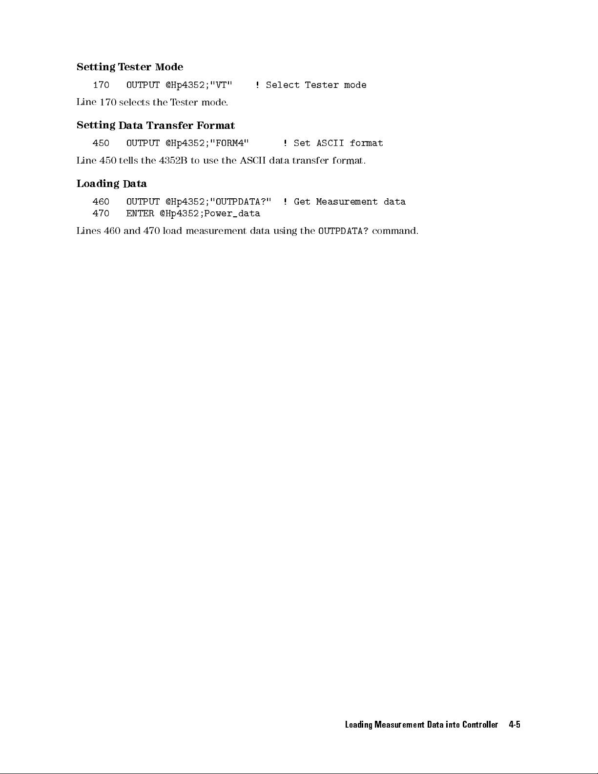
Setting
Tester
Mode
170
Line
170 selects
Setting
450
Line
450
Loading
460
470
Lines
460
OUTPUT @Hp4352;"VT"
the
T
ester
mode
Data Transfer
OUTPUT
tells
@Hp4352;"FORM4"
the
4352B
F
to
ormat
use
Data
OUTPUT
ENTER
and
@Hp4352;"OUTPDATA?"
@Hp4352;Power_data
470
load
measurement
.
the
!
ASCII
data
Select
!
data
!
using
Tester
Set
ASCII
transfer
Get
Measurement
the
OUTPDATA?
mode
format
format.
data
command.
Loading Measurement Data into Controller 4-5
Page 54
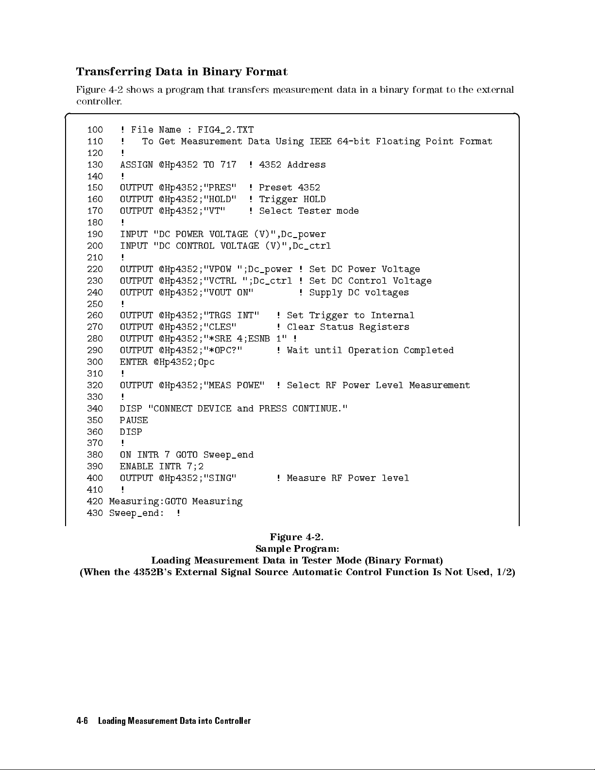
Transferring
Data
in
Binary
F
ormat
Figure
controller
4-2
shows
.
a
program
that
transfers
measurement
data
in
abinary
format to
the external
d a
100 !
110 !
File Name
To
Get
:
FIG4_2.TXT
Measurement
Data
Using
IEEE
64-bit
Floating
Point
Format
120 !
130 ASSIGN
@Hp4352
TO
717
!
4352
Address
140 !
150
160
170
180
190
200
210
220
230
240
OUTPUT
OUTPUT
OUTPUT
!
INPUT
INPUT
!
OUTPUT
OUTPUT
OUTPUT
@Hp4352;"PRES"
@Hp4352;"HOLD"
@Hp4352;"VT"
"DC
"DC
POWER
CONTROL
VOLTAGE
@Hp4352;"VPOW
@Hp4352;"VCTRL
@Hp4352;"VOUT
!
!
!
VOLTAGE
";Dc_power
";Dc_ctrl
ON"
Preset
Trigger
Select
4352
HOLD
Tester
(V)",Dc_power
(V)",Dc_ctrl
!
Set
!
Set
!
Supply
mode
DC
DC
Power
Control
DC
voltages
Voltage
Voltage
250 !
260
270
280
290
300
310
320
330
340
350
360
370
380
390
400
410
420
430
OUTPUT
OUTPUT
OUTPUT
OUTPUT
ENTER
@Hp4352;"TRGS
@Hp4352;"CLES"
@Hp4352;"*SRE
@Hp4352;"*OPC?"
@Hp4352;Opc
!
OUTPUT
@Hp4352;"MEAS
!
DISP
"CONNECT
DEVICE
PAUSE
DISP
!
ON INTR
ENABLE INTR
7GOTO
7;2
Sweep_end
OUTPUT @Hp4352;"SING"
!
Measuring:GOTO
Measuring
Sweep_end: !
INT"
4;ESNB
POWE"
and
PRESS
!
Set
Trigger
!
Clear
1"
!
!
Wait
until
!
Select
CONTINUE."
! Measure
Status
RF
Power
RF Power
to
Internal
Registers
Operation
Completed
Level Measurement
level
Figure 4-2.
Sample Program:
Loading Measurement Data in T
(When the 4352B 's External Signal Source A
4-6 Loading Measurement Data into Controller
ester Mode (Binary F
ormat)
utomatic Control Function Is Not Used, 1/2)
Page 55

440
450
460
470
480
490
500
510
520
530
!
OUTPUT
ASSIGN
OUTPUT
ENTER
ENTER
ENTER
ASSIGN
!
PRINT
@Hp4352;"FORM3"
@Dt
TO
717;FORMAT OFF
@Hp4352;"OUTPDATA?"
@Dt
USING
"%,8A";A$
@Dt;Power_data
@Dt
USING
@Dt
"POWER
"%,1A";A$
TO
*
";Power_data;"
!
Set IEEE
!
Get Measurement
64-BIT Floating
(dBm)"
Point format
data
540 !
550 END
c b
(When
The
ow of
I/O
path
Setting
170
Line 170
Setting
450
460
The
data
format.
I/O
path
program.
How
with
formats?
Loading Measurement
the
4352B
this
to
FORMA
T
ester
OUTPUT
selects
's
program
TOFF
Mode
@Hp4352;"VT"
the
T
Data Transfer
OUTPUT
ASSIGN
transfer
Dening
is
valid
are
data
other
@Hp4352;"FORM3" !
@Dt
using
an
I/O
for
the
transferred
binary
External
is
the
when using
ester
mode
F
ormat
TO
717;FORMAT
the
ENTER
path
binary
data
Signal
same
with
data
Y
the
as
the binary
.
statement
ASCII
transfer
ou
can
GPIB
Figure
Sample
Data
Source
that
for
!
Select
OFF
formatting
used
use
the
command
4-3.
Program:
in
T
ester
A
utomatic
ASCII
data
Tester
Set
on
FORM3
in
following
Mode
data
transfer
IEEE
must
OFF
the
FORM3
(Binary
Control
transfer
format.
mode
64-BIT
be
makes
this
following
data
transfer
in
line
F
ormat)
Function
format.
Floating
performed
possible
lines
(Loading
formats
450.
Is
Not
Y
ou
must
Point
without
(line
460).
Data)
,
by
Used,
set
the
format
data
This
in
the
changing
2/2)
IEEE
32
bit
MS-DOS
oating point
R
personal computer format
format
FORM2
FORM5
Loading Data
470 OUTPUT @Hp4352;"OUTPDATA?"
! Get Measurement data
480 ENTER @Dt USING "%,8A";A$
490 ENTER @Dt;Power_data
500 ENTER @Dt USING "%,1A";A$
FORM3 has an eight-byte header to deal with. The rst two bytes are the ASCII characters
#6. This indicates that a six-byte block data transfer follows, and the next six bytes form an
integer specifying the number of bytes in the data block to follow.To load measurement data,
the header and a byte of terminator \lf^
eoi
" must be also read in lines 480 to 500.
Loading Measurement Data into Controller 4-7
Page 56
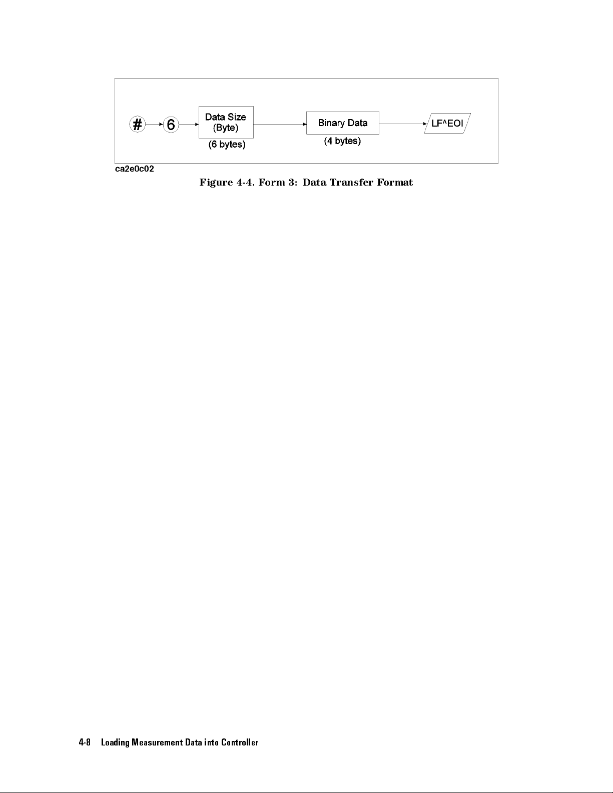
Figure
4-4.
F
orm
3:
Data
Transfer
F
ormat
4-8 Loading Measurement Data into Controller
Page 57
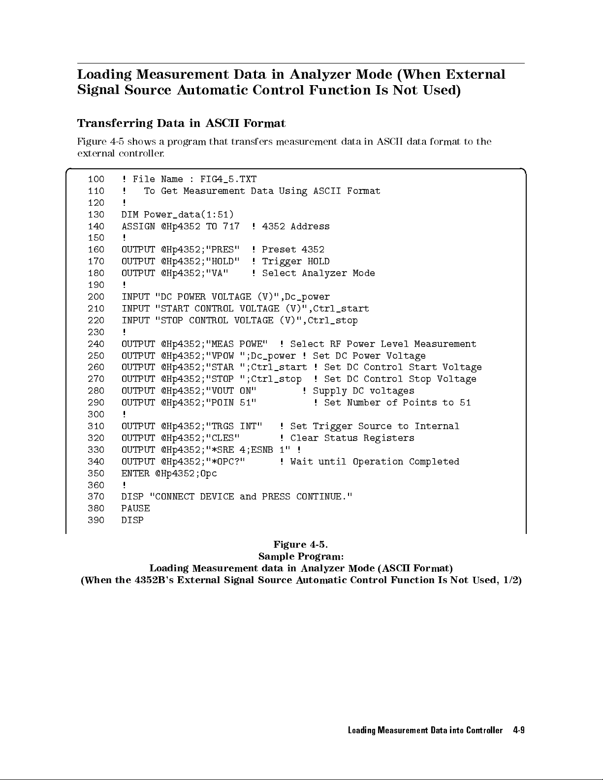
Loading Measurement
Signal
Source A
utomatic
Data in
Control
Analyzer Mode
Function
Is
(When External
Not
Used)
Transferring
Figure
external
4-5 shows
controller.
Data in
a program
ASCII F
ormat
that transfers
measurement
data
in
ASCII
data
format
to
the
d a
100
110
120
130
140
!
File Name
!
To Get
!
DIM
Power_data(1:51)
ASSIGN
@Hp4352
: FIG4_5.TXT
Measurement Data
TO
717 !
4352 Address
Using ASCII
Format
150 !
160 OUTPUT
170
180
190
200
210
220
230
240
250
260
270
280
290
300
OUTPUT
OUTPUT
!
INPUT
INPUT
INPUT
!
OUTPUT
OUTPUT
OUTPUT
OUTPUT
OUTPUT
OUTPUT
!
310 OUTPUT
320 OUTPUT
330 OUTPUT
340 OUTPUT
350 ENTER
@Hp4352;"PRES" !
@Hp4352;"HOLD" !
@Hp4352;"VA"
"DC
POWER
"START
"STOP
VOLTAGE
CONTROL
CONTROL
@Hp4352;"MEAS
@Hp4352;"VPOW
@Hp4352;"STAR
@Hp4352;"STOP
@Hp4352;"VOUT
@Hp4352;"POIN
Preset 4352
Trigger HOLD
!
Select
(V)",Dc_power
VOLTAGE
VOLTAGE
POWE"
";Dc_power
";Ctrl_start
";Ctrl_stop
ON"
51"
@Hp4352;"TRGS INT"
@Hp4352;"CLES" !
@Hp4352;"*SRE 4;ESNB
@Hp4352;"*OPC?" !
@Hp4352;Opc
Analyzer
(V)",Ctrl_start
(V)",Ctrl_stop
!
Select
!
Set
Clear
!
Set
!
!
!
Supply
!
Trigger
RF
Power
DC
Set
DC Control
Set
DC
Set
Number
Status
1" !
Wait until
Mode
Level
Power
Voltage
Control Stop
DC
voltages
of
Source
to
Registers
Operation
Measurement
Start
Voltage
Voltage
Points to
Completed
51
360 !
370
380
DISP
PAUSE
"CONNECT
DEVICE
and
PRESS
CONTINUE."
390 DISP
Figure 4-5.
Sample Program:
Loading Measurement data in Analyzer Mode (ASCII F
(When the 4352B's External Signal Source A
ormat)
utomatic Control Function Is Not Used, 1/2)
Loading Measurement Data into Controller 4-9
Page 58

400
410
420
430
440
450
460
470
480
490
500
!
ON
INTR
7
GOTO Sweep_end
ENABLE
OUTPUT
INTR
@Hp4352;"SING"
!
Measuring:GOTO
Sweep_end:
!
!
OUTPUT
OUTPUT
ENTER
@Hp4352;"FORM4"
@Hp4352;"OUTPDATA?"
@Hp4352;Power_data(*)
7;2
Measuring
!
Measure RF
!
Set ASCII
!
Get Measurement
Power level
format
data
510 !
520
530
540
550
560 END
c b
FOR
PRINT
NEXT
!
I=1 TO
51
"POWER ";Power_data(I);"
I
(dBm)"
(When the
Loading Measurement
4352B's
External Signal
Sample
Data in
Source
Program:
Analyzer
A
utomatic
Specifying Array
130 DIM
Denes
the
specied
Specifying
180
Selects
Setting
the
Data
480
Line
480
tells
Loading
490 OUTPUT @Hp4352;"OUTPDATA?"
Power_data(1:51)
array
that
number
of
measurement
Analyzer
OUTPUT
@Hp4352;"VA"
Analyzer
Transfer
OUTPUT
@Hp4352;"FORM4"
the
4352B
Data
is
Mode
mode
used
.
F
ormat
to use
to
store
points
the ASCII
measurement
(line
290).
!
Select
!
Set
Analyzer
data transfer
!
Get Measurement data
data.
ASCII
format.
500 ENTER @Hp4352;Power_data(*)
Lines 490 and 500 load measurement data array using the
Mode
The
(ASCII
Control
array
Function
Mode
format
OUTPDATA?
F
ormat)
size
must
command.
Is
be
Not
equal
Used,
to
2/2)
the
To Load Other Data
Use the following GPIB command in place
in line 490 to obtain the memory array
Command Reference
Memory array
4-10 Loading Measurement Data into Controller
of
'OUTPDATA?
. See the
GPIB
'
for more information on this command.
OUTPMEMO?
Page 59

Transferring
Data
in
Binary
F
ormat
Figure
external
4-6
shows
controller
a
program
.
that
transfers
measurement
data
in
a binary
data format
to the
d a
100 !
110 !
File Name
To
Get
:
FIG4_6.TXT
Measurement
Data
Using
IEEE
64-bit
Floating
Point
Format
120 !
130 DIM
140 ASSIGN
150
160
170
180
190
200
210
220
230
240
250 OUTPUT
260
270
280
290
300
310
320
330
340
350
360
370
380
390
400
410
420
430
440
Power_data(1:51)
@Hp4352
ASSIGN
@Dt
TO
!
OUTPUT
OUTPUT
OUTPUT
@Hp4352;"PRES"
@Hp4352;"HOLD"
@Hp4352;"VA"
!
INPUT
INPUT
INPUT
"DC
POWER
"START
"STOP
!
@Hp4352;"MEAS
OUTPUT
OUTPUT
OUTPUT
OUTPUT
OUTPUT
@Hp4352;"VPOW
@Hp4352;"STAR
@Hp4352;"STOP
@Hp4352;"VOUT
@Hp4352;"POIN
!
OUTPUT
OUTPUT
OUTPUT
OUTPUT
ENTER
@Hp4352;"TRGS
@Hp4352;"CLES"
@Hp4352;"*SRE
@Hp4352;"*OPC?"
@Hp4352;Opc
!
DISP "CONNECT
PAUSE
DISP
!
ON
INTR
7
GOTO
ENABLE INTR
OUTPUT
@Hp4352;"SING"
TO
717
717;FORMAT
VOLTAGE
CONTROL
CONTROL
DEVICE and
Sweep_end
7;2
OFF
!
Preset
!
Trigger
!
Select
(V)",Dc_power
VOLTAGE
VOLTAGE
POWE"
(V)",Ctrl_start
(V)",Ctrl_stop
!
";Dc_power
";Ctrl_start
";Ctrl_stop
ON"
51"
INT"
!
!
4;ESNB
1"
!
PRESS CONTINUE."
! Measure
!
!
4352
HOLD
Analyzer
Select
!
Set
!
!
!
Supply
!
Set
Trigger
Clear
!
Wait
4352
4352
RF
DC
Set
Set
Set
Status
until
RF
Address
Address
Mode
Power
Level
Power
DC
Control
DC
Control
DC
voltages
Number
Source
Registers
Operation
Power
with
FORMAT
Measurement
Voltage
Start
Stop
of
Points
to Internal
Completed
level
OFF
Voltage
Voltage
to
51
450 !
460 Measuring:GOTO Measuring
470 Sweep_end:
!
Figure 4-6.
Sample Program:
Loading Measurement Data in Analyzer Mode (Binary F
(When the 4352B's External Signal Source A
utomatic
ormat)
Control Function Is Not Used, 1/2)
Loading Measurement Data into Controller 4-11
Page 60

480
490
500
510
520
530
540
550
560
570
580
590 END
c b
!
OUTPUT
OUTPUT
ENTER
ENTER
ENTER
!
FOR
I=1
PRINT
NEXT
!
@Hp4352;"FORM3"
@Hp4352;"OUTPDATA?"
@Hp4352
USING
"#,8A";A$
@Dt;Power_data(*)
@Hp4352
TO
"POWER
USING
"#,A";B$
51
";Power_data(I);"
I
!
Set IEEE
!
Get Measurement
64-BIT format
(dBm)"
data
Loading
(When
The
I/O
Specifying
Denes the
ow
path
130
the
of
to
4352B
this
FORMA
Array
DIM
array
specied number
Specifying
190
Selects
Setting
150
490
As
with
Analyzer Mode
OUTPUT
the
Analyzer
Data
Transfer
ASSIGN
OUTPUT
the
T
ester
Measurement
's
External
program is
T OFF
Signal
the
same
when using
Power_data(1:51)
that
is
used
to
store
of
measurement
@Hp4352;"VA" !
mode
.
F
ormat
@Dt
TO
717;FORMAT
@Hp4352;"FORM3"
mode
,
dening
Sample
Data
Source
as
that
the binary
measurement
points
(line
Select
OFF
an
I/O
path
Figure
Program:
in
the
A
for
300).
!
Set
with ASCII
4-7.
Analyzer
utomatic
ASCII
data
data
transfer
data.
Analyzer
!
4352
IEEE
Mode
Control
transfer
(Binary
Function
format.
format.
The
array
size
Mode
Address
64-BIT
with
format
formatting OFF
F
ormat)
Is
Not
Y
ou
must
be
FORMAT
(line 150)
Used,
must
set
equal
to
OFF
is required.
2/2)
the
the
How
is
data
transferred
with other binary data
Y
ou
can
the GPIB command
formats?
IEEE 32 bit oating point format
MS-DOS
4-12 Loading Measurement Data into Controller
use
the
following
R
personal computer format
FORM3
data
in line 490.
transfer formats
,
by
changing
FORM2
FORM5
Page 61

Loading Measurement
(When
External Signal
Used)
Data in
Source
Analyzer Mode
A
utomatic
Control
Function
Is
Transferring
Figure
the
The
4-8
4352B
external
and
to
measurement
The
4352B
controller
.
Data
Figure
transfer
controller
data
controls
in
ASCII
4-9
show
measurement
passes
from
it
after
the
measurement
F
ormat
programs
data
the
controller
the
measurement.
and
that
.
capability
sends
must
pass
the
measurement
control
to
the
from
4352B
the
and
data to
external controller
receives
the
the external
to
d a
100
110
120
130
140 PASS
150 DIM
160 ASSIGN
170 ENTER
180
190
200
!
File
Name
!
To
Get
!
ABORT
7
CONTROL
Power_data(1:51)
@Hpib TO
@Hpib;Power_data(*)
ASSIGN
@Hpib
!
END
:
FIG4_8.TXT
Measurement
717
7
TO
*
Data
Using
ASCII
Format
c b
(When
Loading
the
4352B
Sample
Program
Measurement
's
External
Data
Signal
Figure
in
for
External
the
Source
4-8.
Analyzer
A
utomatic
Controller:
Mode
(ASCII
Control
F
ormat)
Function Is
Used)
P
assing
P
asses
Specifying
Denes the array that is used to store
specied number of measurement points
Control
140
PASS
the controller
150
DIM
CONTROL 717
capability from
Array
Power_data(1:51)
the external
controller
measurement data. The array size must be equal to the
.
Setting up GPIB
160 ASSIGN @Hpib TO 7
Species the select code for the GPIB interface card.
Transferring Data
170 ENTER @Hpib;Power_data(*)
Loads measurement data from the 4352B into the controller.
Loading Measurement Data into Controller 4-13
to
the
4352B
.
Page 62

d a
100
110
120
130
140
150
160
170
180
190
!
File
Name
!
To
Get
!
DIM
Power_data(1:51)
!
ASSIGN
@Hp4352
!
OUTPUT
OUTPUT
OUTPUT
@Hp4352;"PRES"
@Hp4352;"HOLD"
@Hp4352;"VA"
: FIG4_9.TXT
Measurement Data
TO
800 !
4352 Address
!
Preset 4352
!
Trigger HOLD
!
Select Analyzer
Using ASCII
Format
mode
200 !
210
220
230
240
250 OUTPUT
260
270
280
290
300
310
320
330
340
350
360
370
380
390
400
410 OUTPUT
420 OUTPUT
430 ENTER
440 ASSIGN
INPUT
INPUT
INPUT
!
OUTPUT
OUTPUT
OUTPUT
OUTPUT
OUTPUT
OUTPUT
ENTER
!
!
DISP
"CONNECT
PAUSE
DISP
!
EXECUTE
!
"DC POWER
"START CONTROL
"STOP CONTROL
VOLTAGE (V)",Dc_power
VOLTAGE (V)",Dc_ctrl_1
VOLTAGE (V)",Dc_ctrl_2
@Hp4352;"MEAS POWE"
@Hp4352;"VPOW
@Hp4352;"STAR
@Hp4352;"STOP
@Hp4352;"VOUT
";Dc_power
";Dc_ctrl_1
";Dc_ctrl_2
ON"
@Hp4352;"CLES"
@Hp4352;"*OPC?"
@Hp4352;Opc
DEVICE
and
PRESS
"SING"
@Hp4352;"FORM4"
@Hp4352;"OUTPDATA?"
@Hp4352;Power_data(*)
@Hp4352
TO
*
!
Select
!
Set DC
!
!
!
Supply
!
Clear
!
Wait
CONTINUE."
!
Measure RF
!
ASCII
RF
Set
Set
Status
until
Format
Power
Level
Power
DC Start
DC
Stop
DC
voltages
Registers
Operation
Power level
Measurement
Voltage
Control
Control
Completed
Voltage
Voltage
characteristics
450 !
460
470
ASSIGN
OUTPUT
@Cntlr
TO
721
@Cntlr;Power_data(*)
!
Controller
Address
480 ASSIGN @Cntlr TO *
490 !
500 END
c b
Sample Program for the 4352B :
Loading Measurement Data in Analyzer Mode (ASCII F
(When the 4352B 's External Signal Source A
4-14 Loading Measurement Data into Controller
Figure 4-9.
ormat)
utomatic Control Function Is Used)
Page 63

Specifying
Array
130
As
with the
Specifying
190
Selects
Setting
410
Line
Loading
420
Loads
DIM Power_data(1:51)
external
Analyzer Mode
OUTPUT
the
Analyzer
Data
OUTPUT
410
tells
Data
OUTPUT
measurement
Transferring
460
470
Transfers
ASSIGN
OUTPUT
measurement
controller
,
@Hp4352;"VA"
mode
.
Transfer
F
ormat
@Hp4352;"FORM4"
the
4352B
to
use
@Hp4352;"OUTPDATA?"
data
array
Data
@Cntlr
TO
@Cntlr;Power_data(*)
data
to the
denes
the
with
the
!
Select
ASCII
data
OUTPDATA?
array
721
external controller
that
Analyzer
!
ASCII
transfer
command.
!
Controller
is
used
Format
format.
.
to
store
mode
Address
measurement data.
Loading Measurement Data into Controller 4-15
Page 64

Transferring
Data
in
Binary
F
ormat
Figure
respectively
The
in
both
4-10
program
Figure
programs
4-8
and
.
ow
and
and
Figure
is
basically
Figure
that
4-11
4-9
the
show
the
the
same as
) except
4352B
programs
that
'ASCII
species
for
that for
FORM3
the
external controller
transferring data
FORMAT OFF
as
'for
the
data transfer
in ASCII
I/O path
format.
and the
4352B,
format (programs
must be
specied in
d a
100
110
120
130
140
150
160
170
180
190
200
! File
! To
Name
Get
!
ABORT
PASS
7
CONTROL
!
DIM
Power_data(1:51)
ASSIGN
ENTER
ASSIGN
@Dt
@Dt;Power_data(*)
@Dt
!
:
FIG4_10.TXT
Measurement
717
TO
7;FORMAT
TO
*
Data
OFF
Using
IEEE
64-bit
Floating
Point
Format
210 END
c b
Loading
(When
Measurement
the
4352B
's
Sample
Data
in
External
Figure
Program
the
Analyzer
Signal
for
External
Source
4-10.
Controller:
Mode (IEEE
A
utomatic Control
64-Bit Floating
Function
P
oint
Is
F
ormat)
Used)
4-16 Loading Measurement Data into Controller
Page 65
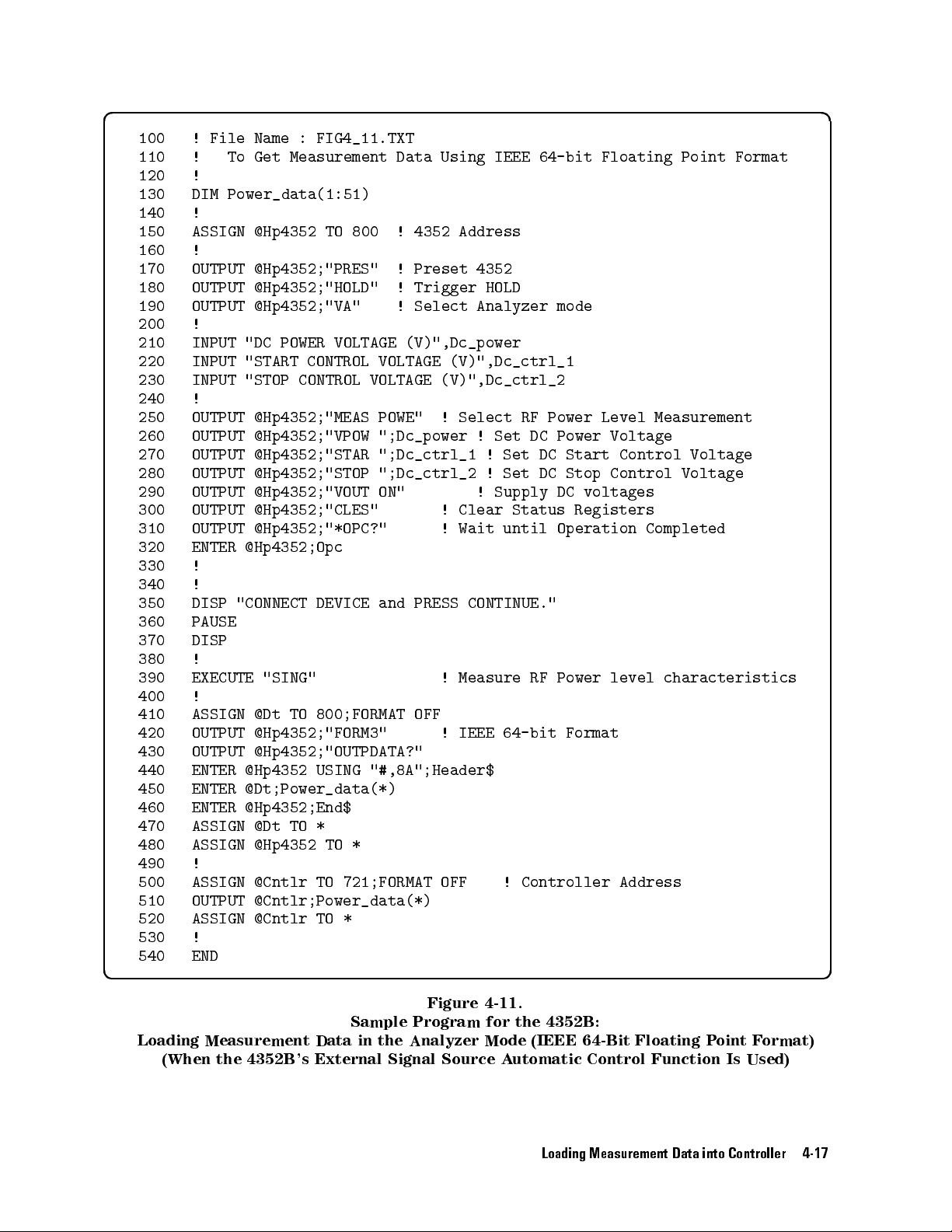
d a
100
110
120
130
140
150
160
170
180
190
!
File
Name
!
To
Get
!
DIM
Power_data(1:51)
!
ASSIGN
@Hp4352
!
OUTPUT
OUTPUT
OUTPUT
@Hp4352;"PRES"
@Hp4352;"HOLD"
@Hp4352;"VA"
: FIG4_11.TXT
Measurement Data
TO
800 !
4352 Address
!
Preset 4352
!
Trigger HOLD
!
Select Analyzer
Using IEEE
64-bit Floating
mode
Point Format
200 !
210
220
230
240
250 OUTPUT
260
270
280
290
300
310
320
330
340
350
360
370
380
390
400
410 ASSIGN
420 OUTPUT
430 OUTPUT
440 ENTER
450 ENTER
460
470
INPUT
INPUT
INPUT
!
OUTPUT
OUTPUT
OUTPUT
OUTPUT
OUTPUT
OUTPUT
ENTER
!
!
DISP
"CONNECT
PAUSE
DISP
!
EXECUTE
!
ENTER
ASSIGN
"DC POWER
"START CONTROL
"STOP CONTROL
VOLTAGE (V)",Dc_power
VOLTAGE (V)",Dc_ctrl_1
VOLTAGE (V)",Dc_ctrl_2
@Hp4352;"MEAS POWE"
@Hp4352;"VPOW
@Hp4352;"STAR
@Hp4352;"STOP
@Hp4352;"VOUT
";Dc_power
";Dc_ctrl_1
";Dc_ctrl_2
ON"
@Hp4352;"CLES"
@Hp4352;"*OPC?"
@Hp4352;Opc
DEVICE
and
"SING"
@Dt
TO
800;FORMAT
@Hp4352;"FORM3"
@Hp4352;"OUTPDATA?"
@Hp4352
USING
"#,8A";Header$
@Dt;Power_data(*)
@Hp4352;End$
@Dt
TO
*
!
!
!
PRESS
!
OFF
!
Select
Clear
Wait
!
Set DC
!
!
!
Supply
RF
Set
Set
Status
until
CONTINUE."
Measure RF
IEEE
64-bit
Power
Level
Power
DC Start
DC
Stop
DC
voltages
Registers
Operation
Power level
Format
Measurement
Voltage
Control
Control
Completed
Voltage
Voltage
characteristics
480 ASSIGN @Hp4352 TO *
490 !
500 ASSIGN @Cntlr TO 721;FORMAT OFF
! Controller Address
510 OUTPUT @Cntlr;Power_data(*)
520 ASSIGN @Cntlr TO *
530 !
540 END
c b
Figure 4-11.
Sample Program for the 4352B:
Loading Measurement Data in the Analyzer Mode (IEEE 64-Bit Floating Point Format)
(When the 4352B 's External Signal Source Automatic Control Function Is Used)
Loading Measurement Data into Controller 4-17
Page 66

Reading Data
The
program
value
.
the
program
each
program.
100
110
120
130
140
150 PRINT
Y
block
ou
can replace
in
OUTPUT
OUTPUT
OUTPUT
ENTER
PRINT
Figure
@Hp4352;Power_max,Swp_prm
"Control
"Maximum Power
Using the
shown
below uses
lines 470
4-6 with
@Hp4352;"MKR
@Hp4352;"SEAM
Marker Search
the marker
onward of
this program
ON"
MAX"
@Hp4352;"OUTPMKR?"
Voltage
";Swp_prm;" (V)"
Level ";Power;"
search function
the program
block in
! Set
Marker function
! Search
!
Read Marker
Function
to search
in Figure
order to
4-5 or
search for
Maximum Level
values
(dBm)"
for the
lines 480
the maximum
ON
maximum
onward
value on
of
Searching
100
OUTPUT
110
OUTPUT
Line
100
turns
trace
.
T
o
Use
Other
Functions
for
Maximum V
@Hp4352;"MKR
@Hp4352;"SEAM
on
the
marker
Marker
alue
ON"
MAX"
and
line
110
Commands
used
SMKR{1-4}
Commands
Move
specied
Moves
specied
Commands
Move
specied
Move
specied
used
the
X-coordinate
the
measurement
used
the
X-coordinate
the
measurement
Commands used
Move
the
specied
X-coordinate
!
Set
Marker
!
Search
moves
ON
marker
marker
to
,
to
to
the
turn
DMKR
move
to
to
move
sub-marker
sub-marker
to move
1marker
to
function
Maximum
marker
on
the
Level
to the
sub-marker
{ON|FIX|TRAC}
the
marker
1
the
the
point.
the
sub-marker
to
the
to
the
point
the 1marker
the
ON
maximum value
or
1marker
MKRPRM
MKRP
parameter
parameter
1
SMKRPRM{1-4}
SMKRP{1-4}
1
DMKRPRM
parameter
on
parameter
parameter
the
Move the
specied
1
Be sure to
turn on the desired marker before moving it.
Loading Data
120 OUTPUT @Hp4352;"OUTPMKR?"
OUTPMKR? returns the marker reading.
4-18 Loading Measurement Data into Controller
1marker
to
the
measurement point
! Read Marker values
DMKRVAL
parameter
Page 67

Other Marker
Readings
The
following commands
Marker reading
X-coordinate
Measurement
The
following commands
Sub-marker
X-coordinate
Measurement point
The
following
1marker
X-coordinate
reading
point
reading
commands
can
be
can be
can
be used
used
to
read
MKRVAL?
MKRPRM?
MKRP?
used to
read the
SMKRVAL{1-4}?
SMKRPRM{1-4}?
SMKRP{1-4}?
to read
DMKRVAL?
DMKRPRM?
the
marker:
sub-marker:
the 1marker:
Loading Measurement Data into Controller 4-19
Page 68

Page 69
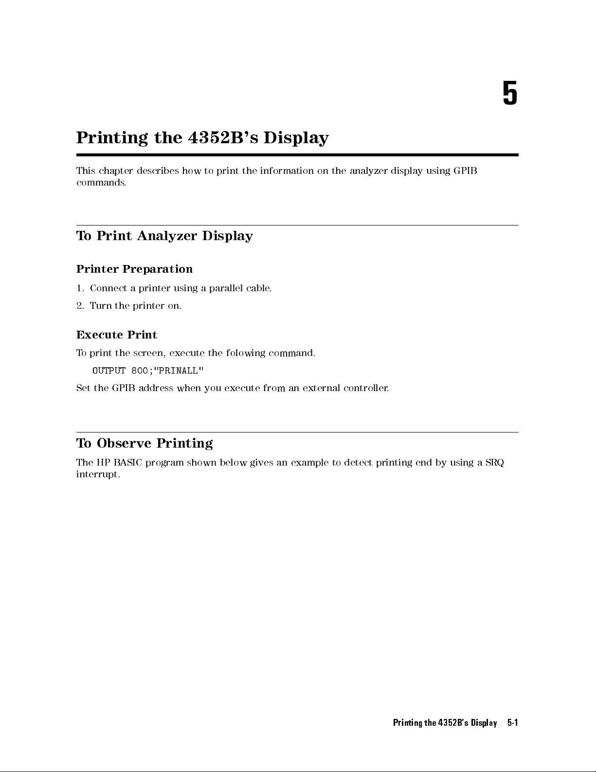
5
Printing
This chapter
describes
commands.
T
o
Print
Printer
1.
Connect
2.
Turn
Execute
T
o
print
OUTPUT
Set
the
Analyzer
Preparation
a
printer
the
printer
Print
the
screen, execute
800;"PRINALL"
GPIB
address
the 4352B
how
to
print
Display
using
a
parallel
on.
the
folowing
when
you execute
's Display
the
information
cable
.
on
command.
from
an
external
the
analyzer
controller
display
.
using
GPIB
T
o
Observe
The HP
interrupt.
BASIC
Printing
program shown
below
gives
an
example
to
detect
printing
end
by
using
Printing the 4352B's Display 5-1
a
SRQ
Page 70

d a
100
110
120
130
140
150
160
170
180
190
200 ENABLE
210 OUTPUT
220
230
240
250
!
FIG5_1.
!
ASSIGN
@Hp4352
!
OUTPUT
OUTPUT
OUTPUT
OUTPUT
OUTPUT
ON
@Hp4352;"CLES"
@Hp4352;"OSNT
@Hp4352;"OSPT
@Hp4352;"OSE
@Hp4352;"*SRE
INTR
8
INTR 8;2
@Hp4352;"PRINALL"
La1:!
GOTO
La1
DISP
"PRINT COMPLETE"
!
To
Observe Printing
TO
800
512"
0"
512"
128"
GOTO La1
!Catch High
!Disable Low
!Enable OS
!Enable OSR
to Low
Transition
to High
Event Reg.
bit
Transitions
260 END
c b
Figure
5-1.
Sample
Program
:
To
Observe Printing
5-2 Printing the 4352B's Display
Page 71
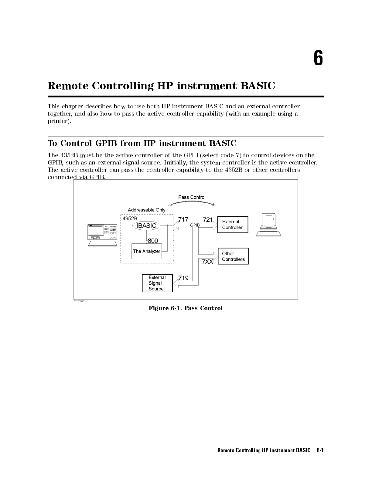
6
Remote
This chapter
together,
and
printer).
T
o
Control
The
4352B
GPIB
,
The
active
connected
such
must
as
controller
via
Controlling HP
describes
also
an
GPIB
how
GPIB
be
the
external
can
.
how
to
pass
from
active
signal
pass
to
use
the
controller
source
the
both
active
HP
controller
instrument B
HP
instrument
controller
B
capability
instrument
of
the
GPIB
(select
.
Initially
,
the
capability
system
to
ASIC
B
ASIC
the
and
an
(with
code
7)
controller
4352B
ASIC
external
an
example
to
control
is
the
or
other
controller
using
a
devices
active
controller
controllers
on
the
.
Figure
6-1.
P
ass
Control
Remote Controlling HP instrument BASIC 6-1
Page 72

What is
controller?
the active
The
active controller
control the
exist at
be a
controller on
passed from
Resetting the
controller)
system
devices connected
a time
controller.
on an
the
one controller
GPIB (this
causes
the
is the
controller
via GPIB
GPIB bus
same
active controller
.
If
there
bus
,
the
to
another
operation can
that
currently
. Only
are
two
active
controller
.
be done
capability to
one
or
only by
has
active
more
capability
the system
be passed
the
capability
controller
devices
can
back to
can
that
to
can
be
the
What
is
the
system
controller?
This chapter
system
d a
c b
controller
100 !
110
120
130
140
150
160
170
180
190
File Name
!
!
PRINTER
ON
Not_active:
PRINT
!
OFF
END
The
system
be
A
controller
used
N
N
ADDRESSABLE
describes
and the
To Receive
IS
ERROR
GOTO
"HELLO
ERROR
controller
controller
passed
controller
in
N
N
either
N
N
N
N
N
N
N
N
N
N
N
N
N
N
N
NN
the
programs
4352B is
:
FIG6_2.TXT
Control
701
Not_active!
!
WORLD!"
that
acts
as
the
master
on
an
GPIB
bus
to
other
controllers
can
be
set
as
.
See
the
controller's
N
NN
N
N
N
N
N
N
N
N
N
N
N
N
N
N
N
N
SYSTEM
a
NN
NN
N
N
N
N
N
N
N
N
N
N
N
N
N
N
N
N
N
N
ONLY
to
used in
(on
!
N
N
NN
NN
NN
(non-system
be
used
N
N
N
N
N
N
ADDRESSABLE
HP
Set
Wait
via
either
N
NN
manual
N
NN
NN
NN
N
N
N
N
N
N
N
N
N
N
when
NN
N
N
N
N
N
N
for
N
N
N
N
pass
N
N
N
N
CONTROLLER
NN
instrument
printer
controller
.
The
GPIB
.
the
system
N
N
N
N
for
N
N
N
N
N
N
NN
NN
NN
(system
controller)
the
external
N
N
N
N
NN
NN
NN
N
N
N
N
N
N
ONLY
BASIC)
address
control
system
controller
details
N
N
N
N
N
N
N
mode.
.
There
controller
.
The
controller)
mode
.
controller
can
be
capability
or
a
non-system
4352B
mode
is
assigned
only one
has
to
or
a
as
cannot
be
the
Figure
Sample
In order
active controller
capability is passed to the 4352B from the
printing is executed in line 160.
To pass the capability of active controller to HP
d a
PASS
While the 4352B has the controller capability, it can talk and listen to devices on GPIB bus.
Therefore, it can send data to and read replies back from printers and plotters.
6-2 Remote Controlling HP instrument BASIC
Program:
to print
CONTROL 717
out to
capability
Pass the Capability of Controller (On External Controller)
T
o
Receive the
the printer
.
4
Return
at address
Therefore
5
Active
,
the
program
external controller
6-2.
Controller Capability
701 in
line 160,
loops
back
instrument B
the
to
. After it is passed to the 4352B ,
ASIC:
(On HP
4352B
line
140 to
instrument
must
receive
150
until
the
the
B
ASIC)
Page 73
Note
Only
the
remote
enable
controller
system
,
these
controller
line
(REN).
commands
can
Even
cannot
assert
when
be
the
GPIB interface
HP
instrument B
used.
clear line
ASIC is
(IFC) and
the active
T
o
return
the
ABORT
REMOTE 7
active
7
controller
assert
assert the
capability
the interface
remote enable
to
the
system
clear line
line (REN)
controller:
(IFC)
d a
Or
PASS
,
you
CONTROL 721
Return
can
return
the
5
4
Return
the
Capability
controller
of
capability
Controller
to
the
system
(On
HP
instrument
controller
by
resetting
B
ASIC)
the
GPIB as
follows:
d a
ABORT
7
4
Return
5
Return
the
Capability
of
Controller
(On
External
Controller)
Remote Controlling HP instrument BASIC 6-3
Page 74

To
Execute an
External
HP instrument
Controller.
BASIC
Command From
the
Note
Combine
F
or
example
the
PROG:EXEC
,
to
The PROGram
the external
execute
subsystem commands
controller.
command
EDIT
with
command,
a
command
in the
to
be
following programs
executed
on
HP instrument
can be
used
BASIC.
on
d a
OUTPUT 717;"PROG:EXEC
Or
you
can
use
single
quotation
""EDIT"""
marks
,
instead
of
the
double
quotation
marks
,
as
follows
.
d a
OUTPUT
Y
ou
have
command
command
717;"PROG:EXEC
to
be
that
\
GET
requires
careful
"FILENAME"
about
a
'EDIT'"
the
command
parameter
",
the
.
F
or
syntax
syntax
example
is
as
follows
when
,
to
executing
execute
.
the
an HP
HP
instrument B
instrument B
ASIC
ASIC
d a
OUTPUT
717;"PROG:EXEC
""GET
""""FILENAME"""""""
6-4 Remote Controlling HP instrument BASIC
Page 75

To
Run an
HP instrument
BASIC
Program From
the External
Controller
d a
100
110
120
130
140
150
160
170
180
190
200
210
220
230
! File
! To
! (On
Name :
FIG6_3.TXT
Run IBASIC
Program From
External Controller)
!
ABORT 7
ASSIGN @Hp4352
TO 717
OUTPUT @Hp4352;"PROG:DEL:ALL"
OUTPUT @Hp4352;"PROG:DEF
OUTPUT @Hp4352;"10
OUTPUT
OUTPUT
OUTPUT
OUTPUT
@Hp4352;"20
@Hp4352;"30
@Hp4352;"
@Hp4352;"PROG:EXEC
MSI "":INTERNAL"""
GET
END"
"
END
#0" !
""FIG1_3.TXT"""
""RUN"""
END
External Controller
! Delete
Download
a
program
a
!
!
Execute
the
program
program
up
to
"END"
c b
Sample
Y
ou
must
drive
of
for
HP
Program:
insert
a
the
4352B
instrument
T
o
oppy
before
B
ASIC
Run
disk
the
that
running
also
contains
HP
instrument
(On
the
contains
this
Figure
External
the
sample
FIG1_3.TXT
6-3.
B
ASIC
Controller)
program
program.
.)
Program
le
FIG1_3.TXT
(The
furnished
From
the
External
into
sample
the
built-in
program
Controller
disk
disk
Open
Scratch any
Transfer
In the HP instrument B
160
170
180
190
200
the
HP instrument
OUTPUT
OUTPUT
program currently
the HP
OUTPUT
OUTPUT
OUTPUT
B
ASIC
Editor
@Hp4352;"PROG:DEL:ALL"
@Hp4352;"PROG:DEF #0"
existing in
instrument B
@Hp4352;"10
@Hp4352;"20
@Hp4352;"30
ASIC editor
MSI
GET
END"
, the following program is now
the HP
ASIC Program
"":INTERNAL"""
""FIG1_3.TXT"""
!
Delete
! Download
instrument
a
program
a
B
ASIC
program
editor
and
up
open
to
the
"END"
editor
.
!
present:
d a
10 MSI ":INTERNAL"
20 GET "FIG1_3.TXT"
30 END
Close the HP instrument BASIC Editor
210 OUTPUT @Hp4352;" " END
Sending the
END
command to the 4352B closes the editor.
Remote Controlling HP instrument BASIC 6-5
Page 76

Run
the
HP
instrument
B
ASIC
Program
220
Line
OUTPUT @Hp4352;"PROG:EXEC
220
runs
the
following
program
in
the
""RUN"""
HP
instrument
!
Execute
BASIC
the
editor:
program
d a
10
MSI ":INTERNAL"
20
GET "FIG1_3.TXT"
30
END
Line 20
T
o
Transfer
retrieves a
Program
program
saved
to
in
the
le
HP
instrument
FIG1_3.TXT
and
B
ASIC
runs
the
program.
d a
100 !
110 !
File
To
Name
:
Transfer
FIG6_4.TXT
the
Program
to
IBASIC
(on
External
Controller)
120 !
130
140
150
160
170
180
190
200
210
220
230 ENTER
240 OUTPUT
250 END
260
270
280
290
ABORT
ASSIGN
INPUT
OUTPUT
OUTPUT
ASSIGN
ON
DIM
LOOP
Done:
OFF
OUTPUT
END
7
@Hp4352
TO
717
"FILENAME?",File_name$
@Hp4352;"PROG:DEL:ALL" !
@Hp4352;"PROG:DEF
@File
ERROR
GOTO
TO
File_name$
Done
Line$[1024]
Line$=""
@File
USING
"K";Line$
@Hp4352;Line$
LOOP
!
ERROR
@Hp4352;"
"
END
#0"
Delete a
! Download
!
!
Transfer
!
End
edit
program
a program
the
program
up
by
to
"END"
each
line
c b
Sample
This
Program:
Program
T
transfers
o
Transfer
a
program
Program
le
saved
external controller to the HP instrument B
Figure
to
ASIC.
6-4.
HP
instrument B
in
the mass
storage
ASIC (on
device
(disk
External Controller)
drive)
of
the
Before you run this program, conrm that the le to be transferred exists on the mass storage
device.
Open the HP instrument B
160 OUTPUT @Hp4352;"PROG:DEL:ALL"
170 OUTPUT @Hp4352;"PROG:DEF #0"
ASIC Editor
! Delete a program
! Download a
program up to "END"
Scratch any program that currently exists in the HP instrument BASIC editor and open the
editor.
6-6 Remote Controlling HP instrument BASIC
Page 77

Transfer
the
Program
180
190
200
210
220
230
240
250
Transfer
controller
Close
the HP
280
Sending
ASSIGN @File
ON
ERROR
DIM
Line$[1024]
LOOP
Line$=""
ENTER
@File;Line$
OUTPUT
END
LOOP
the
program
exits
the
instrument B
OUTPUT
the
4352B
TO
File_name$
GOTO
Done
@Hp4352;Line$
by
line
to
the
loop
and
goes
@Hp4352;"
the
END
" END
command closes
4352B
to
line
ASIC
!
!
.
When
260.
Editor
the editor
Transfer
all program
!End
edit
.
the
program
lines are
by
each
line
transferred, the
Remote Controlling HP instrument BASIC 6-7
Page 78

Page 79

If
You
Have a
7
Problem
This chapter
If
There
Check all
This trouble
cases
.
If
an
Error
Check
the
provides helpful
Is
No
Response
GPIB addresses
is usually
caused
Message
error
message
information
and
cable
by
is
Displayed
on
the
4352B
on
From
connections
an
incorrect
's
how
an
address
display
to
x
typical
problems
Instrument
.
or
a
bad
.
or
on
loose
.
the
GPIB
GPIB
cable
Bus
in
most
If \
GPIB error occurred
" is displayed:
1. Get the error number and description using the
on how to use this command, see the \T
Chapter
3.)
o Report Command Error Occurrence
2. See the appendix \Messages" in this manual.
If any other message is displayed:
See the appendix \Messages" in this manual.
OUTPERRO?
command. (F
If You Have a Problem 7-1
or information
"in
Page 80
If Y
ou Cannot
Get a
File from
the Disk
Check
1.
the oppy
Put the
disk.
disk into
the disk
drive
and
type
as
follows
.
d a
CAT
2. Press
If an
Use another
Check
1.
Put
the
the
4
Return
error
mass
oppy
5
.
message
disk.
If
you
HP
instrument
using
was
storage
disk into
is
displayed,
are
using
B
ASIC
supports
HP
instrument
formatted
.
the disk
B
ASIC
the
the
supports
using
drive
disk
external
the
LIF
B
ASIC,
the
DOS
and
is
corrupted
controller
format
both
the LIF
if
there
format.
type
only,
is
as
follows:
or
the
,
on the
and the
a
possibility
disk
format
other hand,
DOS
format.
that the
does
HP
oppy
not
Try
match.
again
disk
d a
SYSTEM$("MSI")
2.
Press
4
Return
5
.
d a
3.
:CS80,
If
the
to
match.
mass
700,
0
storage
If
you
volume
are
0
mass
does
using
storage
not
HP
instrument
volume
match
your
B
specier
disk
ASIC:
drive
,
use the
MSI
A mass storage volume specier for the built-in disk drive must be
(LIF and DOS). Y
ou have to execute
MSI ":INTERNAL"
in advance
statement
n
.
to set
:,4
it
7-2 If You Have a Problem
Page 81

Check
1.
the le
Put the
type.
oppy disk
into the
disk drive
and type
as follows:
d a
CAT
2. Press
4
Return
5
.
d a
CAT
FILE
NAME PRO
FIG1_3.TXT
FIG2_2.TXT
FIG2_3.TXT
.
.
.
If
you
Only
Use
If
you
T
o
The
an
read ASCII
TYPE
ASCII
PROG
ASCII
are
using
ASCII
the
SA
are using
ASCII
REC/FILE
HP
instrument
type
program
VE/GET
HP
B
type
type
program le
6
6
6
commands
ASIC
program,
BYTE/REC
256
256
256
B
ASIC
le
can
to
use
GET
can
be
be
saved
save
command.
saved
ADDRESS
34
34
34
and read.
and
get
and
29-May-96
29-May-96
29-May-96
ASCII
read
using
DATE
les
.
SA
VE/GET
TIME
11:00
11:00
11:00
commands
.
T
o
read
a
If
The
commands
the
GPIB Command
PROG
PROG
type
.
type
program,
program
Does
le
Not
use
can
W
LO
be
ork
AD
command.
saved
and
read
using
the
STORE/LO
Check the preceding GPIB command.
An GPIB command that requires a long execution time (such as changing format) can aect
the next GPIB command execution.
If
you execute such commands
, insert the following command lines:
OUTPUT @Hp4352;"*OPC?"
ENGTER @Hp4352;Dum
For details,see\ToWait For the Preceding Operation to Complete" in Chapter 3.
AD
If You Have a Problem 7-3
Page 82

Page 83
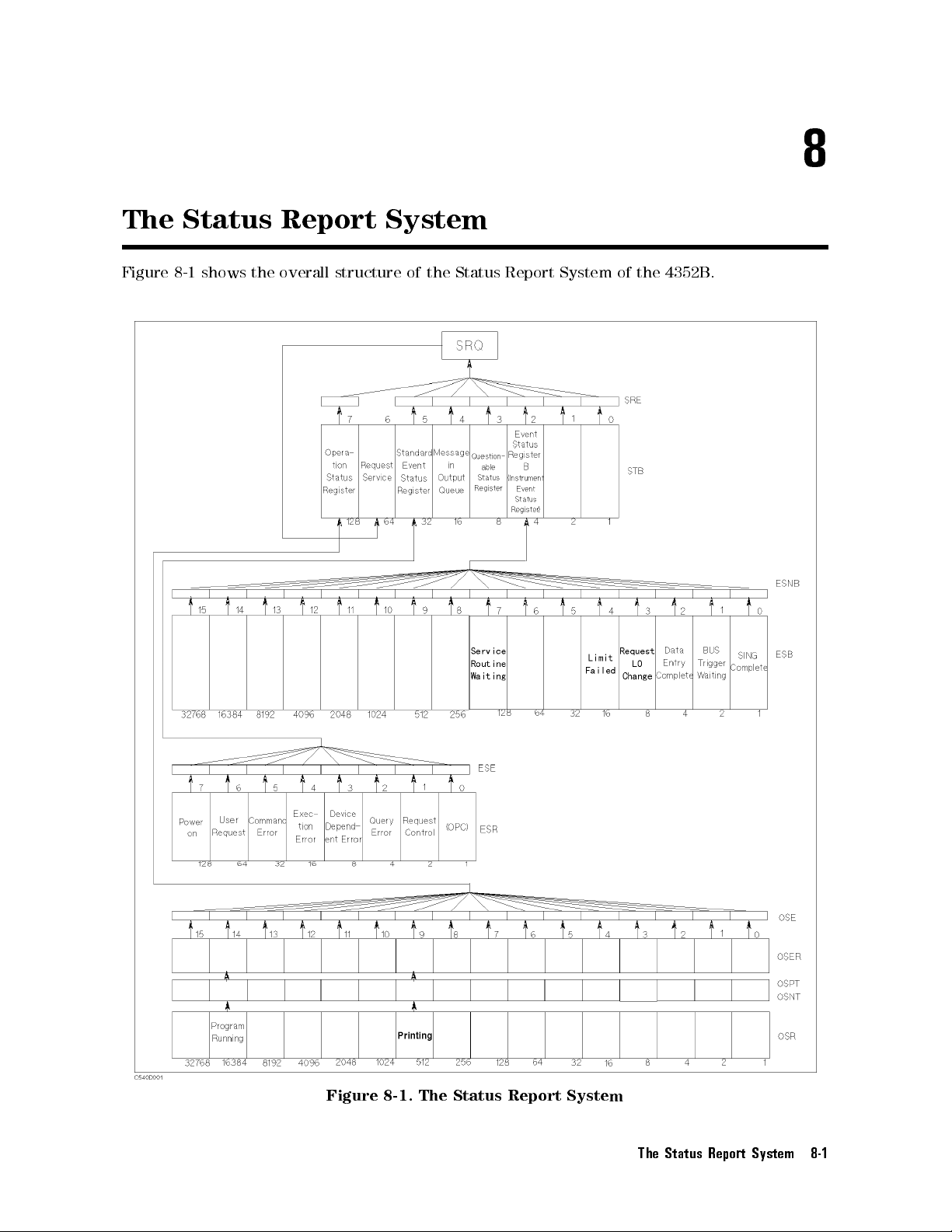
8
The
Figure 8-1
Status Report
shows
the
overall
System
structure
of
the
Status
Report
System
of
the
4352B
.
Figure 8-1. The Status Report System
The Status Report System 8-1
Page 84
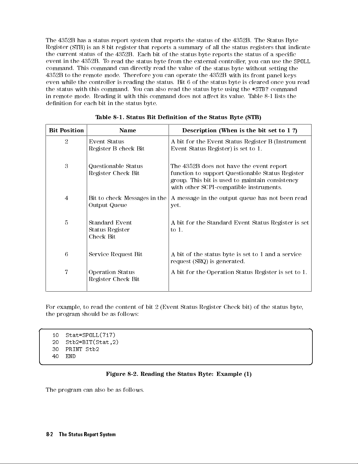
The
4352B has
Register
the
current status
event
in the
command.
4352B
even
the
in
to the
while
status
remote
denition
a status
(STB) is
an
of
4352B
This command
remote
the
controller
with
this
mode
.
Reading
for
each
T
report
8
bit
register
the
4352B
.
T
o
read
can
mode
.
is
command.
it
bit
in
the
able
8-1.
system
that
.
Each
the
status
directly
Therefore
reading
Y
ou
can
with
this
status
byte
Status
that
reports
bit
of
byte
read
you
the
status
also
command
.
Bit
Denition
reports
a
summary
the
from
the
value
can
operate
.
Bit
read
does
the
status
the
6
the
of
status
of
byte
external
of
the
the
of
the
status
not
aect
the
of
the
all
the
reports
controller,
status
4352B
status
byte
its
Status
4352B
.
The
status registers
the status
you can
byte
without
with
its
front panel
byte is
using
value
Byte
cleared once
the
*STB?
.T
able 8-1
(STB)
Status
that indicate
of a
specic
use the
setting
command
lists the
Byte
SPOLL
the
keys
you read
Bit
P
osition
2 Event
3 Questionable
4 Bit
5 Standard
6 Service
7 Operation
Register
Register
to
check
Output
Status
Check
Register
Name Description
A
Status
B
check
Check
Messages
Queue
Event
Register
Bit
Status
Bit
in
the
bit
for
Event
The
4352B
function
group
.
with
other
A
message
yet.
A
bit
for
to
1.
Bit
A
Request
Bit
bit
of
request
Status
A
bit for
Check Bit
the
Event Status
Status
to
This
Register)
does
not
support
bit
is
SCPI-compatible
in
the
the
Standard Event
the
status
(SRQ)
is
generated.
the
Operation
(When
is
have
is
set to
the
Questionable
used
to
maintain
output
byte
queue
is
Status
the
bit
Register B
1.
event
Status
instruments
has
Status
set
to
1
Register
set
to
1
(Instrument
report
Register
consistency
.
not
been
Register
and
a
service
is
set
?)
read
is
to
set
1.
F
or
the
example
program
,
to read
should
the content
be as
follows:
of bit
2 (Event
Status Register
Check bit)
of the
status
byte
,
d a
10 Stat=SPOLL(717)
20 Stb2=BIT(Stat,2)
30 PRINT Stb2
40 END
c b
Figure 8-2. Reading the Status Byte: Example (1)
The program can also be as follows.
8-2 The Status Report System
Page 85
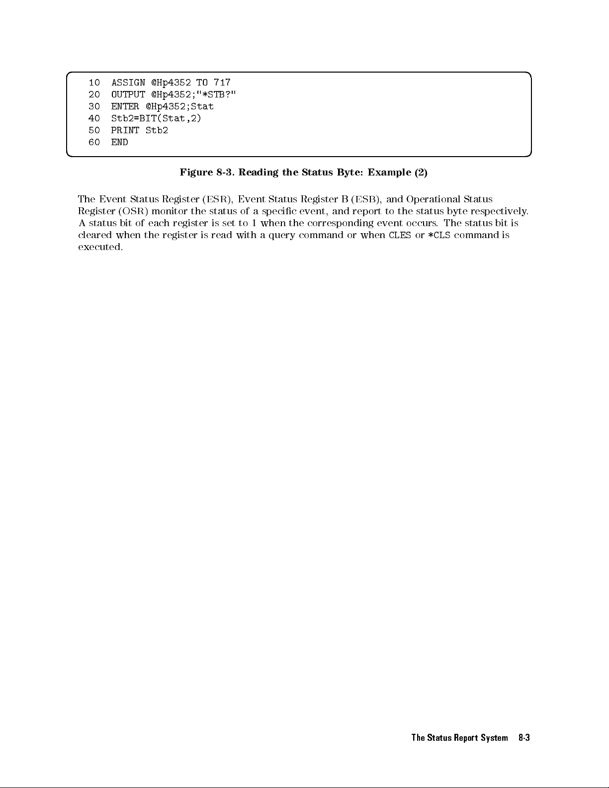
d a
10
ASSIGN
20
OUTPUT
30
ENTER
40
Stb2=BIT(Stat,2)
50
PRINT
60
END
@Hp4352
TO
717
@Hp4352;"*STB?"
@Hp4352;Stat
Stb2
c b
The
Event
Register
A
status
cleared
when
executed.
Status
(
OSR
bit
)
of
the
Register
monitor
each
register
register
Figure
(
the
is
8-3.
ESR
status
is
read
),
set
with
Reading
Event
of
to
a
specic
1
when
a
Status
query
the
Status
Register
Byte:
B
event, and
the
corresponding event
command
Example
(
ESB
report to
or
when
(2)
),
and Operational
the status
occurs.
CLES
or
*CLS
Status
byte respectively
The status
command
bit
is
is
.
The Status Report System 8-3
Page 86
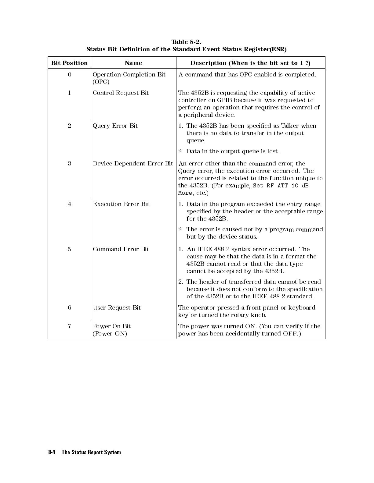
Status
Bit Denition
of
the
T
able 8-2.
Standard
Event
Status
Register(ESR)
Bit P
osition
0 Operation
1 Control
2 Query
3 Device
4 Execution
(OPC)
Name Description (When
A
Completion
Request
Error
Bit
Dependent
Error
Bit
Bit
Bit
Error
Bit
command
The
4352B
controller
perform
a
peripheral
1.
The
4352B
there
queue
2.
Data
An
error
Query
error
the
More
1.
error
occurred
4352B.
, etc
Data
specied
for
the
2.
The error
but
by
that
is
requesting
on
GPIB
an
operation
device
is
no
.
in
the
other
,
the
(F
or
.)
in
the
by
4352B
is
the device
has
because
.
has
been
data
to
output
than
execution
is
related
example
program
the
header
.
caused
is the
OPC
the
that
bit
enabled
capability
it
was
requires
specied
transfer
queue
is
in
lost.
the command
error
to
the
function
,
Set
RF
exceeded
or
the
not
by
a
program
status
.
set
to
1
is completed.
of
active
requested
the
control
as
T
alker
the
output
error,
the
occurred.
unique
ATT
10
the
entry range
acceptable
command
?)
to
of
when
The
to
dB
range
5 Command Error
6 User
7 P
Request
ower On
(P
owerON)
Bit
Bit
Bit
1. An
IEEE
cause may
4352B cannot
cannot be
2.
The
header
because
of
the
The
operator
key
or
turned
The
power was
power
has been accidentally turned
488.2
be
accepted by
of
it
does
4352B
pressed
the
turned
syntax
that
the
read or
transferred
not
conform
or
to
the
a
front
rotary
ON
error
data
that
the
IEEE
knob
.
(Y
occurred.
is
in
the
data
4352B
data
cannot
to
the
488.2
panel
.
ou
can
The
a
format
type
.
be
specication
standard.
or
keyboard
verify
OFF
.)
the
read
if
the
8-4 The Status Report System
Page 87
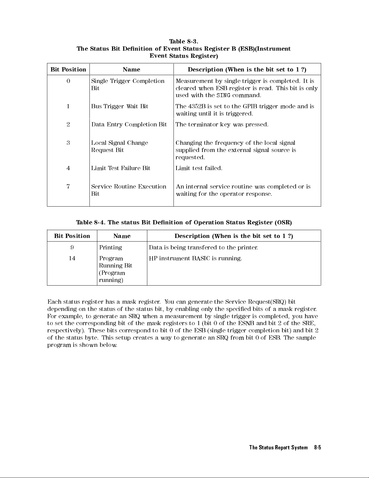
The
Status Bit
Denition
of
Event
T
able 8-3.
Event
Status
Status Register)
Register
B
(ESB)(Instrument
Bit P
osition
0 Single
1 Bus
2 Data
3 Local
4 Limit
7 Service
Bit
P
osition
T
able
Bit
Trigger
Entry
Signal Change
Request
T
Bit
8-4.
The
Name Description (When
Bit
Measurement
cleared
used
The
waiting
The
Changing
supplied
when
with
the
4352B
is
until
terminator
the frequency
from the
set
it
Trigger
Completion
Bit
Completion
W
ait
Bit
requested.
Limit
test
est
F
ailure
Bit
Routine
Execution
An
internal
waiting
status
Bit
Denition
of
Name Description
failed.
service
for
the
Operation
(When
by
single
ESB
register
SING
command.
to
the
is
triggered.
key
was
external signal
routine
operator
Status
is
is the
trigger
is
GPIB
pressed.
of the
was
response
Register
the
bit
bit
is
completed.
read.
trigger
local
source
completed
.
(OSR)
set
to
set
This
mode
signal
1
to
?)
bit
is
1
and
or
is
?)
It is
only
is
is
9 Printing Data
14 Program
Running
Bit
HP
instrument
is
being
transfered
B
ASIC
is
to
the
printer.
running.
(Program
running)
Each status
depending on
For
example,
to set
register has
the status
to generate
the
corresponding
a mask
of the
an SRQ
bit
of
register
status
when a
the
mask
.
Y
ou
can
bit,
by
enabling
measurement
registers
generate
only
by
to
1
(bit
the
the
single
0of
Service
specied
trigger
the
ESNB
Request(SRQ)
bits
of
a
mask
is
completed,
and
bit
2
bit
of
register
you
the
SRE,
have
respectively). These bits correspond to bit 0 of the ESB (single trigger completion bit) and bit 2
of the status byte
program
is shown below
. This setup creates a way to generate an SRQ from bit 0 of ESB
.
. The sample
.
The Status Report System 8-5
Page 88
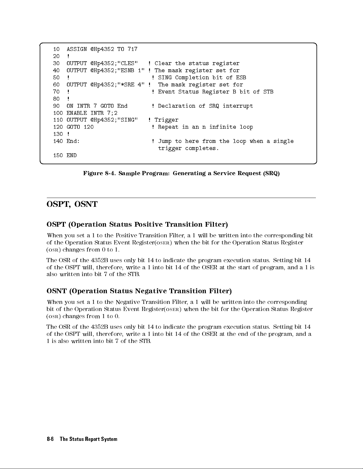
d a
10
ASSIGN
20
!
30
OUTPUT
40
OUTPUT
50
!
60
OUTPUT
70
!
80
!
90
ON
100
ENABLE
110 OUTPUT
120 GOTO
130
!
140
End:
150
END
@Hp4352
TO
717
@Hp4352;"CLES"
@Hp4352;"ESNB
@Hp4352;"*SRE
INTR
7
GOTO End
INTR
7;2
@Hp4352;"SING" !
120 !
!
Clear the
1"
! The
!
SING
4"
! The
!
Event
! Declaration
Trigger
Repeat in
! Jump
trigger
status register
mask register
Completion bit
mask register
Status Register
of SRQ
an n
to here
from the
completes.
set for
of ESB
set for
interrupt
infinite
Bbit
loop
loop
of STB
when
a
single
c b
OSPT
OSPT
When
of
the
(
osr
)
changes
The
OSR
of
the
also
written into
OSNT
When
bit of
the
(
osr
) changes
Figure
, OSNT
(Operation
you
set
a
Operation
from
of
the
OSPT
will,
(Operation
you
set
a
Operation
from
8-4.
1
to
the P
Status
0
4352B
therefore
bit 7
1
to
the
Status
1
Sample
Status
ositive
Event
to
1.
uses
,
of
the
Status
Negative
Event
to
0.
P
ositive
Transition
Register(
only
bit 14
write
STB
.
Negative
Program:
oser
to indicate
a1
into bit
Transition
Register(
Generating
Transition
Filter
,
a
1
) when
the
the
14
of
the
Transition
Filter
,
a
1
oser
)
when
a
Service
Filter)
will
be
bit
for
program
OSER
Filter)
will
be
the
bit
The OSR of the 4352B uses only bit 14 to indicate the program
of the OSPT will, therefore
1 is also written into bit 7 of the STB
, write a 1 into bit 14 of
.
the OSER at the end of the program, and a
Request
written
the
at
written
for
into
Operation
execution
the
start
into
the
Operation
status
of
execution status
(SRQ)
the
corresponding
Status
program,
.
Setting
Register
bit
and
the corresponding
Status Register
. Setting bit 14
bit
14
a
1
is
8-6 The Status Report System
Page 89

9
Command
This chapter
See
this
commands
the
43521A
Commands
Commands
See
the
need
detailed
describes GPIB
chapter
.
Note
(Down
given
are
listed
Function
information
for
Reference for
commands
information
that
some
Converter
in
this
chapter
in
alphabetical
R
eference
of
when
on
on
the
Unit).
are
each
functions
commands
designed
order
you
wish
command.
you
.
Tester
can
use
available
covered
for
measurements
to
search
Mode
for
measurements
with
and
in
this
through
syntax
chapter
in
the
command
in
the
of
are
used
tester
functions
tester
each
mode
of
when
or
mode
these
you
.
when
.
use
you
Command Reference for Tester Mode 9-1
Page 90

The
followings are
1
!
2
!
3
4
!
5
!
A
Switches the
!
VER
tf
Query
f
0
j
1
g
Example
typeface rules
OFF
j
0
j
ON
j
1
averaging function
P
arameter
OFF
or
0
ON
or
1
Response
<
new
line
>
g
<
A
veraging
A
veraging
^END
and
>
denitions
to ON/OFF
function
function
used
N
N
NN
N
AVERAGING ON
.(
OFF
ON
in
this
NN
NN
NN
NN
NN
NN
N
N
Description
command
N
N
N
N
N
N
N
N
N
NN
NN
NN
NN
NN
NN
NN
off
N
N
reference
N
N
N
N
N
N
under
.
4
Bw/Avg
5
key
.)
OUTPUT
OUTPUT
ENTER
1Command
Letters
printed
case
If
range
space
written
without
.
the command
,
or
.)
Characters
symbols
F
or
example
indicates
2This is
a
The front
described in
3This
4This
is
a
is
a
717;"AVER ON"
717;"AVER?"
717;A
names
and
in
any
to
a
character
between
such
as
\
,
f
OFF
that
you
description
panel keys
parentheses.
description
Query
response
required
bold
dene
space
transfer
string,
brackets
j
"
or
\
f
j
0
j
ON
j
1
input
a
of
command.
and
of
parameters for
parameters
a
command.
in-between.
requires
input
,
f
g
,
"
between
g
indicates
number
softkeys
P
arentheses
format
for
Characters
a
constant,
them
with
are
qualiers
commands
that
(1,
2,
3,
that
have
are
the sample
the
sample
Y
ou
must
a
space
and
you
input either
or
4).
the
also
used
command.
type
can
one
or
after
accepted
qualiers
same
function
for
command.
the
command part
be
either
more
by
upper
numbers
a
command.
commands
when
OFF
,
ON,
as
supplemental
case
within
(
t
.
Y
you
actually type
0,
or
the
command
descriptions
exactly
or
lower
the
indicates
ou do
1,
and
as
dened
a
not need
.
f
1-4
g
are
.
5Examples (including
If
a
Note
command
MISMATCH
that of
is
" appears if you attempt to use that command for those items
9-2 Command Reference for Tester Mode
Query
invalid
case
in
specic
usage)
of
measurement
the
sample
items
command.
,
\
ANALYZER
TYPE
.
Page 91

Command Reference
AFC
tf
OFF
j
0
j
ON
j
1
g
Turns
the
automatic
frequency
control
function
ON
or
OFF
AFCMAXV
N
NN
N
N
N
N
N
N
N
N
N
N
N
NN
NN
NN
NN
NN
NN
NN
N
N
N
AFC
.
on
(
OFF
N
under
t
4
Menu
<
numeric
5
key
>
.)
P
arameter
OFF
ON
or
AFCITER
Sets
the
setting
N
N
N
N
N
N
N
N
N
N
N
N
MAX
(
Query
f
numeric
AFCMAXV
Species
used.
The value
is ON.
specied with
priority
level
specied
t
maximum
loop)
N
N
N
N
N
N
NN
NN
NN
N
N
N
N
N
ITERATION
P
arameter
<
numeric
Response
g
the
N
N
N
N
N
N
N
N
N
N
N
N
N
AFC
MAX
(
specied with
This value
over
or
0
1
<
numeric
number
are
repeated.
N
N
N
N
N
N
N
N
N
N
N
N
under
>
<
new
line
t
<
numeric
DC
control voltage
NN
N
N
N
N
N
N
N
N
N
N
N
N
N
N
N
N
N
N
N
N
CTRL
can
MAXVCTRL
that
specied
with
MAXVCTRL
N
N
N
be
NN
><
N
N
N
N
VOLT
.
Sets
the
Sets
the
>
of
times
This
5
key
4
Menu
1
to
999
^END
>
N
N
N
N
N
N
N
N
N
under
this
command
specied
Note,
with
cannot
A
utomatic
A
utomatic
that
value
is
.)
>
upper
4
Menu
irrespective
also
,
that
this
command.
be
Frequency Control
Frequency
the
for
limit
5
key
is
valid
with
applied
Control
measurement
use
with the
Range Unit
when
the
.)
when
of
the
the
4352B
Therefore
to
Description
function OFF
function
automatic
the
maximum
the
device
ON.
and calculation
automatic frequency
automatic
DC
the
value
,
a
voltage
when
.
frequency
frequency
control
specied
level
this
command
(control voltage
control function.
control
voltage
with
that
function
control
level
MAXVCTRL
exceeds
is
function
the
used.
is
has
P
arameter
<
numeric
Query Response
f
numericg<
>
new line
0
to 20
(
0
15 to
35 V
(V
alue
specied
with
AFCMAXV
(Value specied with
with
MAXVCTRL
><
^END
)
)
>
with
Range Unit
with
option
AFCMINV
AFCMAXV)
001)
)
(V
alue
specied
(Value specied
Command Reference for Tester Mode 9-3
V
Page 92

AFCMAXV
t
<
numeric
>
AFCMINV
Species
control
The value
is ON.
the
function.
specied with
This value
specied with
priority over
level specied
P
arameter
<
numeric
Query
f
Response
numeric
g
AFCSENS
Species
frequency
the
control
t
<
numeric
DC
control
N
N
N
N
N
N
N
N
N
N
N
NN
AFC
(
can be
MAXVCTRL
that specied
with
MAXVCTRL
>
<
new line
t
<
numeric
DUT's
approximate
function. (
>
voltage
NN
NN
NN
MIN
NN
NN
NN
N
N
N
N
N
N
CTRL
lower
N
N
N
N
N
NN
NN
this command
specied
.
Note
,
also
with
this
cannot
0
to
20
(
0
(V
with
(V
with
><
alue
alue
15
specied with
AFCMAXV
specied
MAXVCTRL
^END
>
>
tuning
N
N
N
N
NN
NN
N
N
N
N
N
SENSITIVITY
limit.
NN
NN
NN
NN
NN
N
N
N
VOLT
is
,
that
command.
be
to
35
V
)
with
)
sensitivity
N
N
N
N
N
N
N
N
N
N
N
N
N
N
N
This
value
is
under
valid
with
applied
5
4
Menu
when
of
the
the
4352B
Therefore
to
the
for use
key
.)
the
automatic
maximum
the
,
a
device
with the
DC
value
voltage
when
frequency
control
specied
level
that
this
command
Range Unit
use
V
with
with
AFCMINV
AFCMAXV
N
NN
NN
N
N
under
option
)
)
001)
(V
(V
.
4
Menu
alue
alue
This
specied
specied
value
5
key
is
for
.)
automatic frequency
control
voltage
with
exceeds
the
function
level
MAXVCTRL
the
is
used.
automatic
has
P
arameter
<
numeric
Query
f
AFCT
Species
function.
Response
numeric
ARG
the target
g
N
N
N
N
TARGET
(
Parameter Range Unit
<
numeric
Query Response
f
numericg<
>
<
new
t
<
numeric
N
N
N
N
N
N
N
NN
NN
NN
>
new
0
line
><
frequency.
NN
N
under
10E6 to 3E9 (4352B only) Hz
Frequency band min to Frequency band max (when
43521A is used)
line><^END
1000000000
^END
>
>
This value
5
.)
4
Menu
>
Range Unit
to
0
100
and
100
to
1000000000
is for
use
with
the
automatic
Hz/V
frequency
control
Hz
9-4 Command Reference for Tester Mode
Page 93

A
VERREST
AFCTOL
Species
the actual
4
5
.)
Menu
P
arameter
<
numeric
Query
f
A
VER
Turns
Response
numeric
tf
the
P
arameter
OFF
Query
Response
t
<
the
allowable
setting
g
<
OFF
A
veraging
or
ON
or
numeric
frequency
>
new line
j
0
j
ON
function
0
1
>
dierence
in
2000
to 2000000
><
^END
j
1
g
A
veraging
A
veraging
(frequency
the
>
ON
or
function
function
automatic
N
N
AVERAGING
OFF
.
(
OFF
ON
resolution)
frequency
between
control
the
target
function.
frequency
NN
NN
N
N
N
N
N
N
N
N
TOLERANCE
(
Range Unit
Hz
N
N
N
N
N
N
N
N
N
N
N
N
NN
NN
NN
N
N
N
N
N
N
N
N
N
N
N
N
N
N
N
N
N
N
N
NN
NN
NN
N
N
N
N
on
OFF
N
under
4
Bw/Avg
5
key
Description
N
N
N
and
NN
NN
NN
NN
NN
NN
NN
under
.)
f
0
j
1
g
<
new
line
><
^END
>
A
VERF
Species
N
NN
AVERAGING
(
A
CT
t
<
numeric
the
N
N
N
N
N
N
N
N
N
N
N
NN
N
averaging
N
N
N
N
N
N
N
N
N
N
N
N
N
N
N
N
N
N
N
N
N
N
N
N
N
N
N
N
N
N
N
N
N
FACTOR
factor
under
>
(number
4
Bw/Avg
5
key
of
.)
times
for
averaging) for
the
averaging
Parameter Range Unit
<
numeric
>
1
to
power
1,
2,
999
4,
,or
.
(when
DCI)
.
.
,
the
256
(when the
measurement
measurement item
item
sets
frequency
sets FM
,
Deviation)
1,
2,
4,
.
.
.
,
4096
(when
the
measurement
item
sets
C/N)
Query Response
f
numericg<
new line
><
^END
>
AVERREST
Resets the averaging function to restart the count from the next measurement.
NNNNNNNNNNNNNNNNNNNN
(
AVERAGING RESTART
NNNNNNNNNNNNNNNNNNNNNNNNN
NNNNNNNN
under
4
Bw/Avg
5
key. No Query
.)
function.
Command Reference for Tester Mode 9-5
Page 94

CNB
W
Sets
the converted
key
.)
t
<
numeric
>
noise bandwidth
at the
C/N Ratio
measurement.
N
NN
NN
NN
NN
NOISE
(
NN
N
N
N
N
N
N
N
N
N
N
N
NN
BW
NN
under
4
Bw/Avg
5
P
arameter
<
numeric
Query
f
Response
numeric
g
CNOFREQ
Sets
the
oset
measurement.
P
arameter
<
numeric
Query
f
Response
numeric
g
CONT
Sets
the
trigger
updated
at every
>
<
new
t
<
numeric
from
N
N
N
N
N
OFFSET
(
>
<
new
mode
1
to 1000000
line
><
^END
>
the
carrier frequency
N
N
N
N
N
NN
NN
NN
N
N
N
N
N
N
N
N
N
N
N
N
N
FREQ
100
line
><
^END
to
the
N
N
trigger
CONTINUOUS
.
(
N
N
N
N
N
N
under
to
10000000
A
utomatic
N
N
N
NN
N
N
N
N
N
N
N
Range Unit
Hz
>
4
Bw/Avg
for the
noise measurement
5
key
.)
at
the
C/N
Ratio
Range Unit
Hz
>
N
N
N
N
N
N
N
N
N
Continuous
N
N
N
N
NN
N
N
N
under
4
T
rigger
mode
5
key.)
.
In
this
mode
,
a
measured
value
is
Query
f
CTRLDL
Sets
after
0
j
1
g
<
the
changing
Response
new line
Y
t
wait
Parameter Range Unit
<
numeric
Query Response
f
numericg<
><
^END
<
numeric
time
required for
the control
>
new line
>
>
10E
><
the DUT
voltage.
0
3to1
^END
>
response until
N
N
N
N
N
N
NN
NN
NN
NN
N
N
CTRL
(
N
N
N
N
N
N
N
N
N
N
N
DELAY
N
N
N
N
N
under
the DUT's
4
DC
Control
RF
5
output
key
signal
is
stable
.)
sec
9-6 Command Reference for Tester Mode
Page 95

D
A
TO
VAL
t
<
numeric
>
CTRL
P
V
CAL
erforms DC
Query)
CTRLV
Enables or
N
N
N
CTRLV
(
CORR
NN
NN
NN
NN
N
N
N
N
N
N
N
N
N
N
N
CORR on
P
arameter
OFF
ON
Query
f
D
A
Response
0
j
1
g
<
TGAIN
Denes the
P
arameter
<
numeric
control voltage
tf
OFF
disables the
N
N
N
N
N
N
NN
NN
NN
NN
N
N
N
N
N
N
N
N
N
OFF
or
0
or
1
new
line
><
t
<
numeric
gain value
>
calibration. (
j
0
j
ON
j
1
g
compensation obtained
N
N
N
N
N
N
N
N
under
4
DC
Control
compensation
compensation
^END
>
>
for the
data
math
0
100
to
100 (except
OFF
ON
N
NN
NN
NN
EXECUTE
5
key.)
function.
0)
NN
NN
N
N
N
N
N
N
N
N
N
N
N
NN
NN
NN
NN
NN
NN
NN
N
N
N
N
N
N
N
N
N
N
N
NN
NN
from
CTRLV CAL
the
DC
control
NN
under
4
DC
voltage
5
Control
key.
calibration.
Description
N
N
NN
NN
NN
NN
N
N
N
N
GAIN
(
under
4
Displa
5
key
.)
y
Range Unit
No
Query
f
DA
Stores
Query
Response
numeric
TMEM
the
.)
g
<
new
current
line
><
^END
measurement
>
data
into
the
memory
Example
OUTPUT
DA
TOVALt<
717;"DATMEM"
numeric
>
Denes the oset value of a data math function. (
P
arameter
<
numeric
>
0
15E9 to 15E9
Range Unit
Query Response
f
numericg<
new line><^END
>
.
(
N
NNNNNNNNNNNNNNNNNNN
OFFSET
N
NN
NN
N
N
DATA
under
N
N
N
N
N
N
N
N
N
!
N
N
N
N
N
N
NN
NN
NN
MEMORY
4
Display
NN
N
N
N
N
N
N
N
under
5
key.)
4
Displa
5
key
.
y
No
Command Reference for Tester Mode 9-7
Page 96
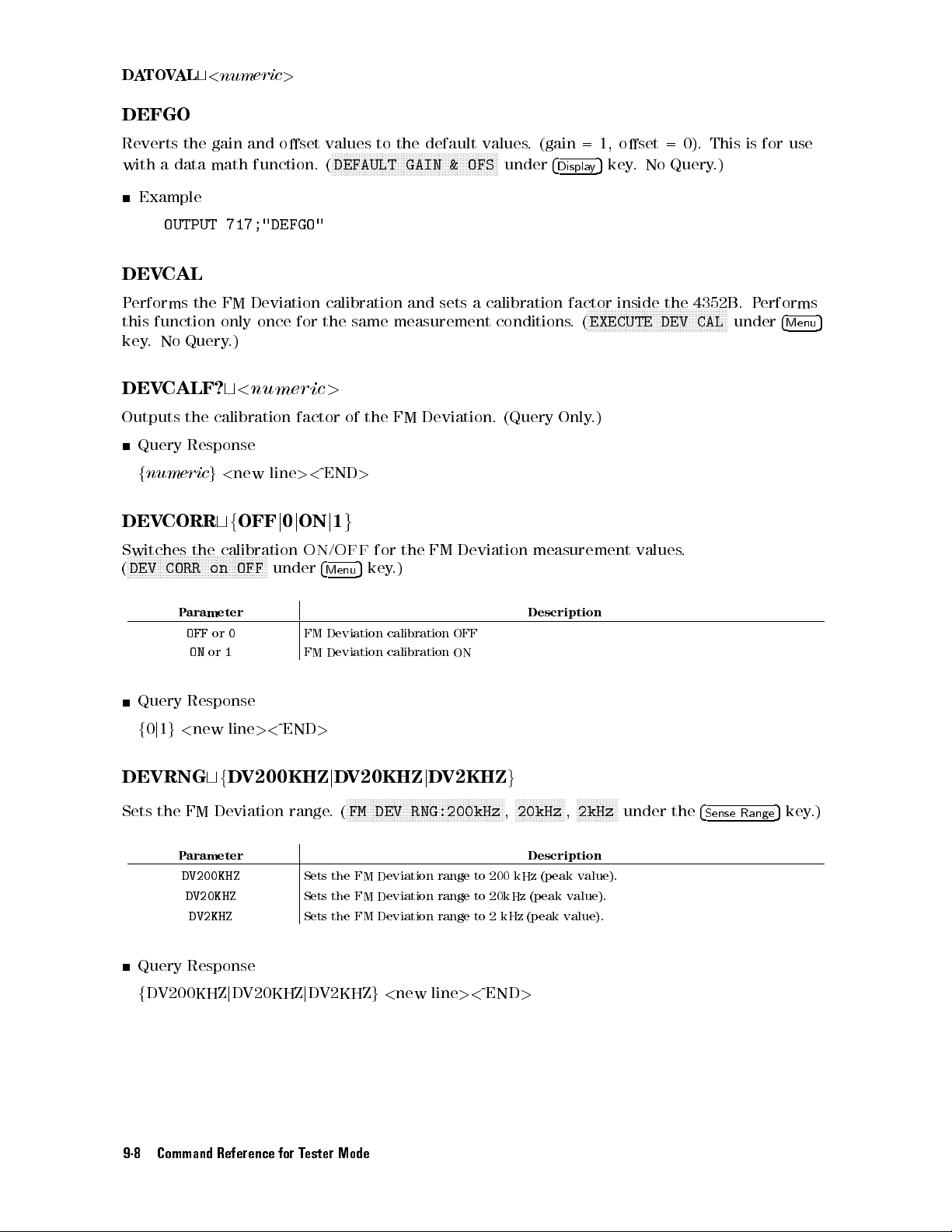
D
A
TO
VAL
DEFGO
t
<
numeric
>
Reverts
with a
DEV
P
erforms the
this
key
DEV
Outputs
DEV
Switches
N
N
N
DEV
(
the
data
Example
OUTPUT
CAL
function only
.
No
Query
CALF?
the
Query
f
numeric
CORR
N
N
N
N
N
N
N
N
NN
NN
N
N
N
N
N
CORR
gain
math
717;"DEFGO"
FM Deviation
.)
t
<
calibration
Response
g
<
new
tf
OFF
the
calibration
N
N
N
N
N
N
N
N
N
N
N
N
N
N
N
N
NN
NN
on
OFF
and
oset
function.
once for
numeric
factor
line
><
j
0
j
ON
N
N
N
under
ON
N
N
N
N
values
(
calibration and
the
>
^END
j
/
4
Menu
to
NN
NN
N
N
DEFAULT GAIN
of the
1
g
OFF
the
N
N
N
N
N
N
N
N
N
NN
NN
NN
NN
same
measurement
FM Deviation.
>
for
5
key
.)
NN
NN
the
default
NN
N
N
N
N
N
N
N
FM
N
N
N
N
NN
NN
NN
NN
NN
&
OFS
sets a
Deviation
values
. (gain
NN
NN
N
N
under
calibration
conditions
(Query
measurement
4
Display
factor
.
Only
=1,
oset =
5
key
inside
N
NN
NN
NN
N
N
N
N
EXECUTE
(
.)
.
N
N
N
N
N
N
N
values
No
Query
the
N
N
N
N
N
N
NN
NN
NN
DEV CAL
0). This
.)
4352B
NN
N
N
N
N
N
N
N
N
N
N
N
N
.
N
N
N
under
is for
.
P
use
erforms
4
Menu
5
P
arameter
OFF
or
0
ON
or
1
Query
f
DEVRNG
Sets
Query Response
f
Response
0
j
1
g
<
new line
tf
the FM
Parameter Description
DV200KHZ
DV20KHZ
DV2KHZ
DV200KHZjDV20KHZjDV2KHZg<
><
D
V200KHZ
Deviation range
FM
Deviation
FM
Deviation
^END
>
j
D
.(
Sets the FM Deviation range to 200 kHz
Sets the FM Deviation range to 20kHz (peak value).
Sets the FM Deviation range to 2 kHz (peak value).
calibration
calibration
V20KHZ
N
N
N
N
N
NN
NN
NN
FM
DEV RNG:200kHz
j
DV2KHZ
NN
N
N
N
N
N
N
N
N
N
N
N
N
N
N
N
new line><^END
Description
OFF
ON
g
N
N
N
N
N
N
N
N
NN
N
N
NN
NN
NN
NN
N
N
N
N
N
N
N
N
N
N
N
N
N
N
N
,
NN
20kHz
>
N
N
NN
NN
N
N
N
,
NN
2kHz
NN
NN
N
(peak value).
NN
N
under the
4
Sense
Range
5
key.)
9-8 Command Reference for Tester Mode
Page 97
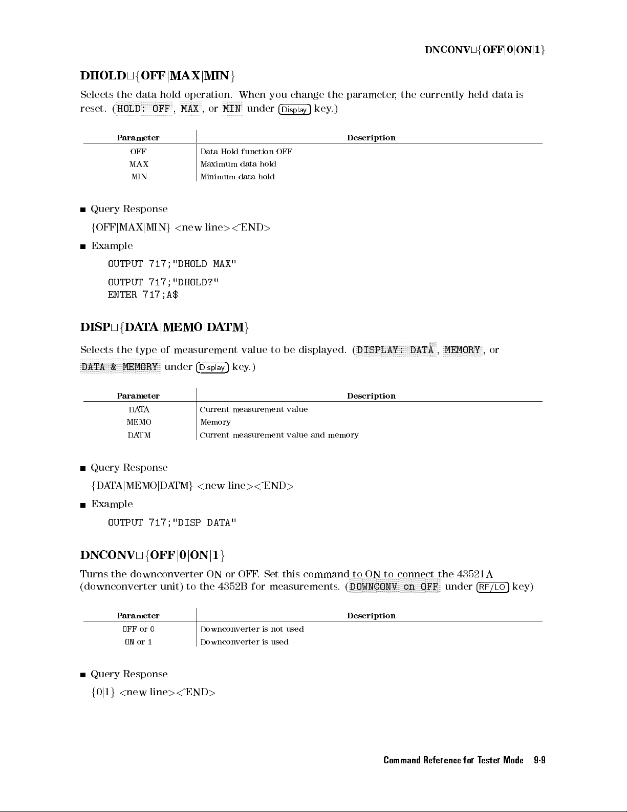
DNCONV
tf
OFF
j
0
j
ON
j
1
g
DHOLD
Selects
reset. (
the
NN
HOLD: OFF
P
Query
f
OFF
j
Example
OUTPUT
OUTPUT
ENTER 717;A$
DISP
tf
Selects
N
N
N
the
N
NN
NN
N
N
N
N
N
N
N
N
N
N
N
N
DATA &
tf
OFF
j
MAX
j
MIN
data
hold
operation.
NN
NN
N
NN
N
N
N
N
N
N
N
N
N
N
N
NN
NN
NN
NN
N
N
N
N
N
,
MAX
N
,
or
NN
NN
NN
arameter
OFF Data
MAX Maximum
MIN Minimum
Response
MAX
j
MIN
g
<
new
line
717;"DHOLD
717;"DHOLD?"
D
A
T
A
j
type
N
N
N
N
N
N
N
N
N
NN
NN
MEMORY
of
N
N
N
N
N
N
N
N
MEMO
under
j
DA
measurement
4
Displa
NN
NN
MIN
Hold
><
MAX"
TM
5
y
g
When
N
N
N
N
N
N
N
function
data
data
^END
value
key
under
hold
hold
g
.)
you
>
to be
change
4
Display
OFF
displayed. (
5
key
the
parameter
.)
Description
N
N
N
N
N
N
N
N
N
N
NN
NN
N
N
N
N
N
DISPLAY:
,the
currently held
N
N
N
N
N
N
N
N
N
N
N
N
N
N
N
N
NN
DATA
NN
N
N
,
N
N
N
N
N
N
N
N
N
N
NN
NN
MEMORY
N
N
N
N
N
N
data is
,
or
P
arameter
D
A
T
A
Current
measurement
value
MEMO Memory
Query
f
DA
TA
D
A
TM
Response
j
MEMO
j
D
A
TM
g
<
Current
new
measurement
line
><
^END
value
>
and
memory
Example
OUTPUT
DNCONV
Turns the downconverter ON or OFF
717;"DISP DATA"
tf
OFF
j
0
j
ON
j
1
g
.
Set this command to ON to connect the 43521A
(downconverter unit) to the 4352B for measurements
Parameter Description
OFFor0
Downconverter is not used
ONor1
Query Response
f0j1g<new line><^END
>
Description
NNNNNNNNNNNNNNN
NNNNNNNNNNNNNNNNNNNNNNNNN
DOWNCONV on OFF
.
(
NNNNNNN
under
4
RF/LO
5
key)
Command Reference for Tester Mode 9-9
Page 98
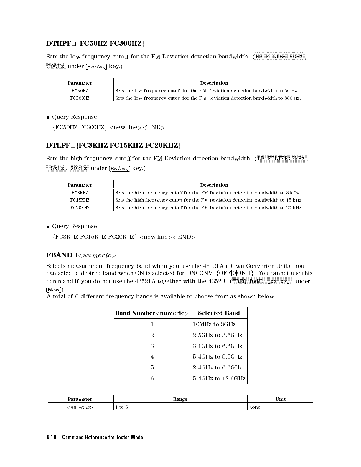
DTHPF
Sets
the low
NN
NN
NN
NN
N
N
N
N
N
N
N
N
N
300Hz
tf
FC50HZ
frequency cuto
under
4
Bw/Avg
j
FC300HZ
5
key
.)
g
for the
FM Deviation
detection
bandwidth.
N
NN
NN
NN
NN
NN
N
N
N
N
N
HP
FILTER:50Hz
(
N
N
N
N
N
N
NN
NN
NN
NN
NN
NN
NN
N
N
N
N
N
N
N
N
,
Query
f
FC50HZ
DTLPF
Sets
the
N
N
N
N
N
N
N
N
N
N
N
NN
NN
N
N
15kHz
,
Query
f
FC3KHZ
P
arameter
FC50HZ
FC300HZ
Response
j
FC300HZ
tf
FC3KHZ
high
frequency
N
N
N
N
N
N
N
N
N
N
N
NN
NN
20kHz
P
arameter
FC3KHZ
FC15KHZ
FC20KHZ
Response
j
FC15KHZ
N
N
under
Sets
the
Sets
the
g
<
new
j
FC15KHZ
cuto
4
Bw/Avg
Sets
the
Sets
the high
Sets the
j
FC20KHZ
low
frequency
low
frequency
line
><
^END
j
FC20KHZ
for
the
5
key
.)
high
frequency
frequency cuto
high frequency
g
<
new
>
FM
Deviation
line
cuto
cuto
cuto
cuto
><
for the
for
g
for
for
for
^END
Description
FM Deviation
the
FM
Deviation
detection
Description
the
FM
Deviation detection
the
FM
Deviation
the
FM
Deviation
>
detection bandwidth
detection
bandwidth.
detection
detection
bandwidth
N
N
N
N
N
N
N
N
N
N
N
N
NN
NN
NN
LP
FILTER:3kHz
(
bandwidth to
bandwidth
bandwidth
to 50
to
N
N
N
N
N
to
to
300
N
N
N
N
N
N
3 kHz.
15
20
N
Hz.
N
Hz.
N
N
N
N
N
kHz.
kHz.
N
NN
NN
NN
N
,
FB
AND
Selects
can
command
4
Meas
A
measurement
select
5
)
total
of
Parameter Range Unit
<
t
<
numeric
a
desired
if
you
6
dierent
numeric
do
>
>
frequency
band
when
not
use
frequency
Band Number
1to6 None
the
band
when
you
use
the
43521A
ON
is
selected
43521A
bands
together
is
<
1 10MHz
2 2.5GHz to 3.6GHz
3 3.1GHz
4 5.4GHz to 9.0GHz
5 2.4GHz to 6.6GHz
6 5.4GHz to 12.6GHz
for
available
numeric
DNCONV
with
the
to
choose
Selected Band
>
4352B
(Down
tf
OFF
.
from as
to 3GHz
to 6.6GHz
Converter
j
0
j
ON
j
1
N
N
FREQ
(
g
N
N
N
N
N
N
N
N
N
N
N
N
N
NN
NN
NN
BAND
shown below
.Y
NN
N
N
N
Unit).
ou
cannot
N
N
N
N
N
N
N
N
N
N
N
N
N
[xx-xx]
.
Y
ou
use
N
N
N
N
N
under
this
N
NN
NN
NN
NN
9-10 Command Reference for Tester Mode
Page 99
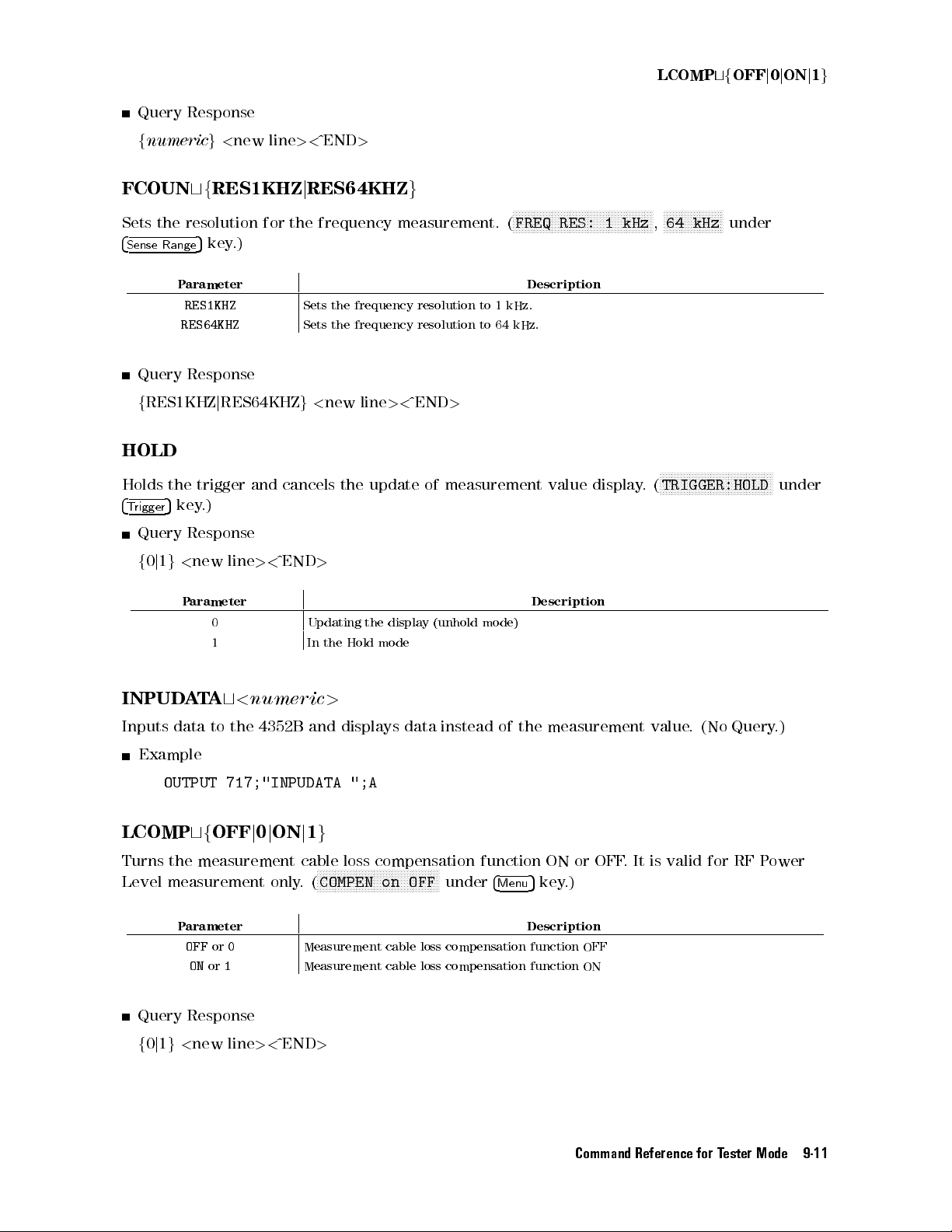
LCOMP
tf
OFF
j
0
j
ON
j
1
g
Query
f
numeric
FCOUN
Sets
the
4
Sense
Range
Query
f
RES1KHZ
HOLD
Holds
the
4
5
rigger
key
T
Query
f
0
j
1
g
Response
g
<
tf
RES1KHZ
resolution
5
key
.)
P
arameter
RES1KHZ
RES64KHZ
Response
j
RES64KHZ
trigger
.)
Response
<
new line
new
and
for
><
line
><
^END
j
RES64KHZ
the
frequency
Sets
Sets the
g
<
cancels
^END
>
>
measurement.
the
frequency
frequency resolution
new
line
><
the
update
g
resolution
^END
>
of
measurement
to
1
to 64
N
N
N
N
N
N
N
N
N
N
NN
FREQ
(
Description
kHz.
kHz.
NN
NN
NN
NN
NN
RES:
value
NN
N
N
N
N
N
N
N
display
N
N
N
N
N
N
N
N
N
N
NN
NN
NN
NN
N
N
N
N
NN
NN
NN
NN
NN
NN
1
64
kHz
,
N
N
N
N
TRIGGER:HOLD
.
(
NN
kHz
under
N
N
N
N
N
N
N
N
N
N
N
N
NN
NN
NN
N
N
N
N
N
N
N
N
N
N
N
N
N
N
N
N
under
INPUD
Inputs
data
P
arameter
0 Updating
1 In
A
T
A
t
<
numeric
to
the
4352B
and
the
Hold
>
displays
the
display
mode
(unhold mode)
data
instead of
Description
the measurement
Example
OUTPUT
LCOMP
Turns the measurement cable loss compensation function ON or OFF
Level measurement only
717;"INPUDATA
tf
OFF
j
0
j
ON
";A
j
1
g
NNNN
NNNNNNNNNNNNNNNNNNNNNNNNN
COMPEN on OFF
.(
NNNNNNNNNNNN
under
4
Menu
5
key.)
Parameter Description
OFF
ONor1
or
0
Measurement
cable loss compensation function OFF
Measurement cable loss compensation function ON
Query Response
f0j1g<new line><^END
>
value.
(No Query
. It is valid for RF P
.)
ower
Command Reference for Tester Mode 9-11
Page 100

LO
A
UTO
tf
OFF
j
ON
j
0
j
1
g
Turns
(
the
N
N
N
N
N
N
N
NN
NN
NN
NN
automatic
NN
NN
NN
N
N
N
N
LO CONTROL
P
arameter
OFF
ON
Query
f
0
j
1
Response
g
<
new
LOFREQ?
Outputs
current
LOSS
Species
N
N
N
N
LOSS
(
Query
f
numeric
t
N
N
NN
N
N
N
N
N
N
under
the
carrier
Response
<
numeric
the
NN
NN
N
N
N
N
N
N
N
N
N
N
N
NN
auto
or
0
or
1
line
frequency
frequency
g
<
new
cable
4
Menu
NN
NN
><
loss
5
NN
NN
line
key
control
NN
NN
N
N
N
N
N
MAN
under
A
A
^END
(Hz)
.
><
>
at
.)
function
utomatic
utomatic
>
that
(Query
^END
DC
(0
4
RF/LO
Control
Control
must
Only
>
Hz)
for
5
key
function
function
be
.)
level.
the
.)
set
It
external
OFF
ON
to
the
is
valid for
signal
Description
external
RF P
generator
signal
generator
ower
Level
(local signal)
in relation
measurement
ON or
to the
only
OFF.
.
P
arameter
<
numeric
Query
f
LOSWT
Species
after
under
Response
numeric
t
the
the
frequency
4
RF/LO
g
<
Parameter Range Unit
<
numeric
Query Response
f
numericg<
>
<
new
line
numeric
wait
time
setup
5
key
.)
>
new line
Range Unit
0
20
to
+20
><
^END
>
>
required
for
of
the external
the
signal
signal generator
from
the external
is completed.
signal generator
0to1 sec
><
^END
>
dB
(
N
N
N
LO
N
N
N
N
N
N
N
N
NN
NN
SWTCH
NN
gets stable
NN
N
N
N
N
N
N
N
N
N
N
N
N
N
N
N
N
N
NN
TIME
NN
N
9-12 Command Reference for Tester Mode
 Loading...