

Optimizing the Agilent high-throughput
analysis system for high performance
and precision
Abstract
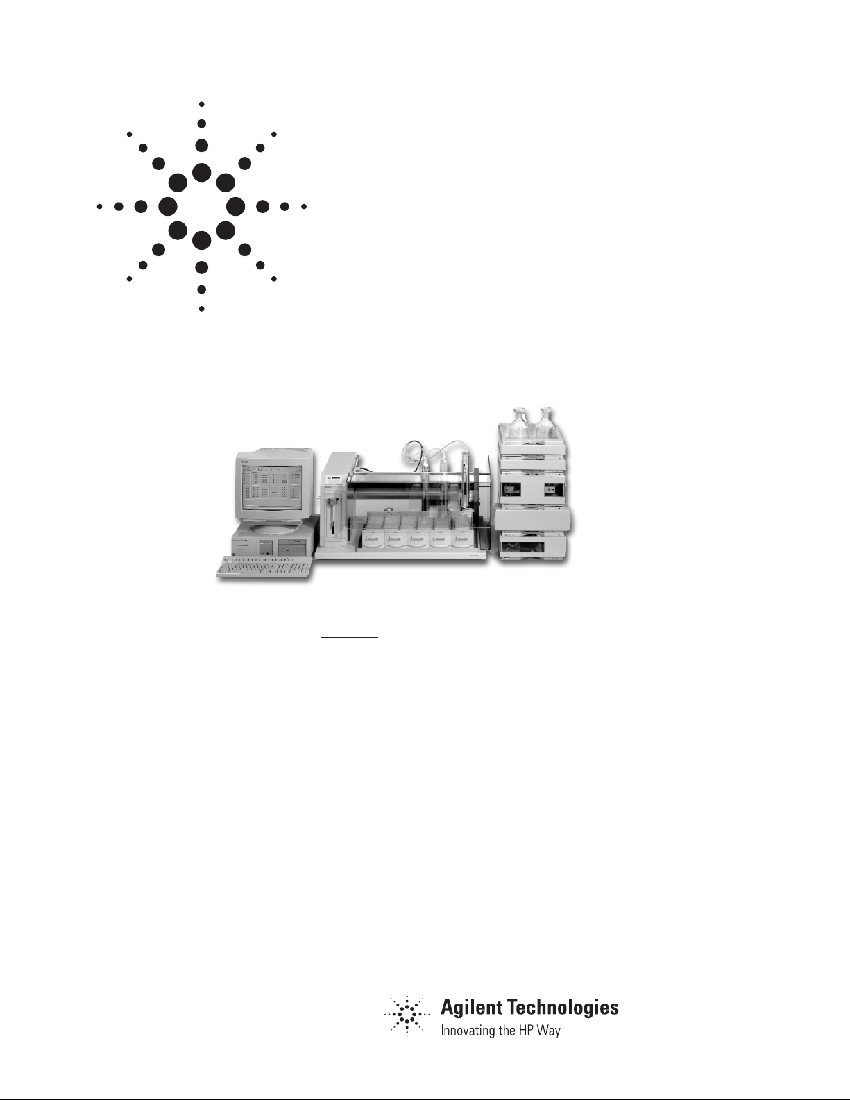
The Agilent 220 micro plate sampler—integrated into the Agilent 1100
Series LC system—is the ideal tool to analyze large numbers of struc-
turally distinct compounds. It offers the full potential of well plate
technology:
• High sample capacity to increase sample throughput and shorten
response times. This is especially useful for drug discovery, combi-
natorial chemistry, medicinal chemistry and natural product analysis.
• The flexibility of having a sampler mode for high-speed sample
analysis and a fraction collector mode for sample isolation and
purification.
• An automated injector program for sample preparation such as
derivatization, dilution and mixing.
• The ability to store and inject over 4,600 samples (using 384-well
plates) for unattended high-throughput.
Technical Note

Equipment
All experiments were carried out
on the Agilent 1100 Series HPLC
system consisting of
• Agilent 1100 Series vacuum
degasser,
• Agilent 1100 Series binary
pump,
• Agilent 1100 Series thermostatted column compart
ment,
• Agilent 1100 Series diode
array detector, and
• Agilent 220 micro plate
sampler.
The system was controlled using
the Agilent ChemStation (version
A.07.01) and the micro plate sampling software (version A.03.01).
Injection principle
In contrast to the Agilent 1100
Series autosamplers the Agilent
220 MPS works with a fixed-size
sample loop injection (figure 1).
While the valve is in loading position the amount of drawn sample
is injected into the fixed size sample loop capillary and the surplus
of sample is flushed through the
loop into waste. To achieve
optimal performance overfilling of
the sample loop is recommended.
The overfill volume depending on
loop size is shown in table 1.
The reason why overfilling is necessary is the hydrodynamic behavior of fluids as they pass through
tubing. A process called laminar
flow takes place under conditions
in which molecules close to the
tubing walls are slowed by frictonal forces. The result is a bulletshaped profile in which the molecules in the center of the stream
travel roughly twice the velocity
of those at the tubing wall3.
The surplus of sample volume also
ensures that the dead volume of
the injector port capillary of
approximately 4.2 µl is completely
flushed with sample. After switching the valve into the injection and
run position the amount of sample
in the loop is applied to the
system.
To apply sample amounts smaller
than the loop volume the Centered
Loop Fill or the Partial Loop Fill
& Inject commands can be used.
For the Centered Loop Fill technique a sandwich of 1-µl air gaps
and sample is injected into the
sample loop. The volume drawn
before the air gaps and the sample
volume is calculated by the software to position the sample volume in the middle of the sample
loop. The precision for this technique is lower than for complete
loop fill because only the
Introduction
The Agilent 220 micro plate sampler (MPS)1is an essential part of
Agilent’s system for combinatorial
chemistry and high throughput
HPLC analysis. It combines high
sample capacity, high speed and
sampling/fractionation capabilities in one system. In combination
with the Agilent 1100 Series HPLC
system using mass selective
detection it is a complete system
that fulfills the requirements of
combinatorial chemistry and highthroughput analysis, offering
robustness, ruggedness, sensitivity, selectivity and speed. The integrated system plus the single software platform simplifies system
setup, operation and management
of large amounts of data.
Details of the Agilent 220 MPS
and how it works in an Agilent
system for combinatorial chemistry or high throughput screening
is described in another Agilent
technical note2. In this note we
explain how to further optimize
the hardware and software setup
of the Agilent 220 MPS to achieve
higher performance and precision.
Loop Volume [µl] Sample Volume [µl]
535
10 40
20 55
50 95
Figure 1
Injection principle of the Agilent 220 micro plate sampler
6
5
4
3
2
1
6
5
4
3
2
1
Loading position Injection and run position
to column
to column
from pump
from pump
waste
waste
injection port
4.2 µl dead volume!
sample loop
(fixed size)
sample loop
(fixed size)
Table 1
Sample loop sizes and recommended sample
volumes

0
1
2
3
4
5
0 20406080100
Sample Volu me [µl]
RSD Area [%]
5 µl Sample Loop
20 µl Sample Loop
mechanical precision of the dilutor syringe determines the injected sample volume. For Partial
Loop Fill & Inject the sample volume plus a relatively large rinse
volume is drawn from the sample.
The rinse volume is used to rinse
the injection port and the sample
loop before the actual sample volume is pushed into the sample
loop. The precision is higher than
for Centered Loop Fill but also
more sample volume is required.
Parameters to optimize
Parameters influencing the performance of the sampler in sampling
mode are:
1. Drawn sample volume
(complete loop fill)
2. Draw speed
(complete loop fill)
3. Size of air gap
(complete loop fill)
4. Dilutor syringe size and sample
loop size (centered loop fill)
1. Drawn sample volume
(complete loop fill)
Although the size of the sample
loop determines the injected sample volume the amount of drawn
sample volume also influences the
precision of the measurement3.
Figure 2 shows the precision of
peak areas for ten measurements
for different drawn sample volumes
For the drawn sample amount of
5 µl the precision of peak area is
very high because 5 µl is just
enough sample to fill the injection
port capillary (dead volume
4.2 µl). Increasing the sample vol-
ume also increases the precision
of peak area. When the recommended sample volume is used
the precision is usually optimized.
More sample volume does not
increase the precision any further.
If not enough sample volume for
sufficient overfill of the sample
loop is available, a lower precision
of peak area results.
2. Draw speed
(complete loop fill)
The draw speed for the sample as
well as the inject speed influences
the precision of the measurement
as shown in figure 3.
Figure 3
Precision of peak area for different draw and inject speeds (5-µl sample loop, complete loop fill)
0.0
0.2
0.4
0.6
0.8
1.0
1.2
0.5 ml/min 1 ml/min 2 ml/min 3 ml/min
Draw Speed
RSD Area [%]
Figure 2
Precision of peak area for different sample volumes (5 and 20-µl sample loop, complete loop fill)

The best precision is achieved
with the lowest draw speed of 0.5
ml/min, which is still higher than
the default draw speed of the Agilent ChemStation (0.2 ml/min).
Table 2 shows the necessary combined times for the Create Air
Gap, Draw Sample and Inject
steps for different sample volumes
and different draw speeds.
The times required for the Create
Air Gap, Draw Sample and Inject
steps are in the range of a few seconds, which shouldn't make much
difference for normal chromatographic runs. For high throughput
analysis with run times in the
range of 60–120 seconds a time of
13.56 seconds (55-µl sample vol-
ume, draw speed 0.5 ml/min) is
about 10–20 % of the whole run
time. Therefore it might be necessary to use higher draw speeds.
For a draw speed of 3 ml/min the
Create Air Gap, Draw Sample
and Inject time of 2.26 seconds is
only 2–4 % of the whole run time.
The disadvantage of higher draw
speed is lower precision of the
analysis.
3. Size of air gap (complete
loop fill)
It is strongly recommended to
insert a Create Air Gap command
before the Draw Sample command in the CC-Mode method.
The air gap prevents mixing of the
sample with the solvent in the
tube connected to the dilutor
syringe. The optimal size of the air
gap can be seen in figure 4.
An air gap between the sample
and the solvent in the tube connected to the dilutor syringe is
necessary to avoid mixing of sample and solvent. The size of the air
gap should be between 1 and 4 µl,
with a recommended size of 2–3
µl. The size of the air gap must not
be larger than the dead volume of
the injection port capillary of
about 4.2 µl. For an air gap size of
5 µl, for example, some of the air
gap is moved into the sample loop
during injection. The effect is evident for an air gap size of 10 µl.
The loop is half filled with air
from the air gap. Therefore less
sample volume is applied to the
system.
Figure 4
Precision of peak area for different air gap sizes
Draw Speed 0.5 ml/min 1 ml/min 3 ml/min
Sample Volume
35 µl 8.76 s 4.38 s 1.46 s
55 µl 13.56 s 6.78 s 2.26 s
Table 2
Times for Create Air Gap, Draw Sample and Inject steps for different sample volumes and draw
speeds
0
1
2
3
4
5
0 µl 3 µl 5 µl 10 µl
Air Gap Size
RSD Area [%]

Dilutor syringe size and sample loop size (centered loop
fill)
To inject sample volumes smaller
than the sample loop size the Cen-
tered Loop Fill command is used.
Figure 5 shows how a sandwich of
air gaps and sample is injected
into the sample loop. The sizes of
the air gaps are calculated by the
software by placing the sample in
the middle of the sample loop (figure 5).
For Centered Loop Fill the precision of the drawn sample amount
depends on the mechanical precision of the dilutor syringe. Therefore, the precision of peak area
for Centered Loop Fill is lower
than for complete loop fill
4,5
. The
solvent volumes for different sample volumes are shown in table 3
(100-µl sample loop). While the air
gap volumes are fixed (1 µl) the
upper solvent volume is calculated by the software by placing the
sample volume in the middle of
the sample loop. The area precisions for different sample volumes for two different dilutor
syringe sizes are shown in
figure 6.
The precision of peak area
increases by applying more sample volume to the sample loop. It
is recommended to fill the sample
loop to at least 50 % of the loop
size. Figure 6 shows that the precision of peak area is about 1 % at
50 µl sample volume. When using
the 500-µl syringe the values are
slightly higher than for the 100-µl
syringe
4,5
.
Figure 5
Centered Loop Fill
Needle
Upper Solvent Volume
Upper Air Gap
Sample drawn from vial
Lower Air Gap
Solvent already in Sample Loop
Injection Port
Tubing
Sample Loop
Figure 6
Precision of area for different sample volumes for two different dilutor syringe sizes
0
2
4
6
8
10
12
14
16
5 µl 10 µl 20 µl 50 µl 80 µl
Sample Volume
RSD Area [%]
100 µl Syringe
500 µl Syringe
Sample Upper Solvent Upper Air Gap Sample Lower Air Gap
Volume [µl] Volume [µl] Volume [µl] Volume [µl] Volume [µl]
551 15 1
10 48 1 10 1
20 43 1 20 1
50 28 1 50 1
80 13 1 80 1
Table 3
Solvent volumes, upper and lower air gap sizes for different sample volumes (100-µl sample loop)

Partial Loop Fill
The CC-Mode software (version
A.03.01) offers a new Partial Loop
Fill feature. In addition to the
sample volume a rinse volume is
drawn from the sample. The rinse
volume is used to flush the sample
loop before the actual sample volume is placed in it. The advantage
over the Centered Loop Fill is
better precision (figure 7),
however, the sample volume
required is much higher. Therefore, the decision which partial
loop fill mode is used depends on
the application. If high reproducibility is required and large
sample volume is available the
Partial Loop Fill should be selected. If only small sample volumes
are available the Centered Loop
Fill with the disadvantage of
lower reproducibility has to be
used.
Carry over
The Agilent 220 MPS and its software offer different options to
minimize carry over, such as the
wash vial and the rinse options6.
The effects of these options on
carry over are shown in table 4.
Important commands to remove
carry over are the rinse functions
Rinse Needle Outside, Rinse
Needle Inside and Rinse Injection
Port. For the sample used in this
experiment the effect of the wash
vial on the carry over was minimal, however, it becomes very
important for samples with higher
viscosity.
Figure 7
Area precision for Centered and Partial Loop Fill
0
1
2
3
5 µl 10 µl 30 µl
Sample Volu me
RSD Area [%]
Centered Loop Fill
Partial Loop Fill
Carry over [%]
Sample concentration No rinse or
Wash Vial Wash Vial
for 1 s,
Rinse Needle
[mg/l] wash function for 1 s
Outside
and
Rinse Injection Port
with 100 µl, 2 ml/min
100 3.2 2.9 0.1
200 1.9 1.9 0.1
300 2.2 1.6 0.1
500 1.9 1.3 0.1
1000 1.7 1.4 0.1
Table 4
Carry over results

Results
The Agilent 220 micro plate sampler is a precise instrument for
high throughput analysis of large
numbers of samples. To optimize
the performance for sample injection the parameters and settings
listed in table 5 have to be taken
into consideration.
Parameters/Settings
Drawn sample volume If enough sample volume is available the sample loop should be
(complete loop fill) overfilled with the recommended sample volume. The re-
commended sample volumes for different sample loop sizes are
shown in table 1.
Draw speed The draw speed for
Create Air Gap, Draw Sample
and
Inject
(complete loop fill) should be set to 0.5 ml/min or less. Higher draw speeds lead to
decreasing precision. The time saved is minimal.
Size of air gap Create an air gap before sample is drawn.
(complete loop fill) The size of the air gap should be between 1–4 µl, 2–3 µl are
recommended.
The size of the air gap must not exceed 4 µl.
Dilutor syringe size and When using
Centered Loop Fill
a sample loop filled to at least
sample loop size 50 % should be used.
(centered loop fill) The volume of the dilutor syringe should be the same
or higher than the sample loop, but still as small as possible.
Partial Loop Fill The partial loop filling technique is used when high reproducibili
ty is required and large sample volume is available.
Carry over To avoid carry over use the commands
Rinse Needle Inside
,
Rinse Needle Outside
and
Rinse Injection Port
.
Use the
Wash Vial
command, especially for samples with high
viscosity.
Conclusion
This technical note described the
optimization of the Agilent 220
MPS hardware and software for
highest precision. The optimal settings for drawn sample volume,
draw speed, size of the air gap
and dilutor syringe size and sample loop size were evaluated.
Furthermore, it was demonstrated
how carry over could be minimized. This information should
help optimize the Agilent 220 MPS
for high performance and precision.
Table 5
Summary of results

Copyright © 2000 Agilent Technologies
All Rights Reserved. Reproduction, adaptation
or translation without prior written permission
is prohibited, except as allowed under the
copyright laws.
Printed 07/2000
Publication Number 5980-0494E
References
1.
“Agilent 220 micro plate sampler
with Agilent 1100 Series: A solution for high throughput HPLC
analyses and purification” Agilent
brochure, 2000, publication num-
ber 5968-9101E
2.
“Agilent 220 micro plate sampler
with Agilent 1100 Series system
for flexible, high throughput HPLC
analyses” Agilent technical note,
1999, publication number 59685322E
3.
John W. Dolan “Injection Loop
Adsorption” LC/GC International,
1996, 4, 530-533
4.
John W. Dolan “Autosampler Precision” LC/GC International,
1998, 10, 910-914
5.
John W. Dolan “Maintaining
Autosampler Performance” LC/GC
International, 1997, 7, 418-422
6.
Jin Y. Huang, Travis Culley, John
W. Dolan “Late Elution and Carryover Peaks - A Case Study” LC/GC
International 1999, 4, 208-211
Udo Huber is an application
chemist based at Agilent
Technologies, Waldbronn,
Germany
For more information on our products and services, visit our website at:
http://www.agilent.com/chem
 Loading...