

Page 1

Agilent Technologies
FieldFox MW VNA/SA
Service Guide
This manual provides documentation for the following instruments:
FieldFox MW Analyzers - N9913A, N9914A, N9915A, N9916A, N9917A, N9918A
FieldFox MW VNA - N9925A, N9926A, N9927A, N9928A
FieldFox MW SA - N9935A, N9936A, N9937A, N9938A
Ma
nufacturing Part Number: Part Number N9927-90003
Printed in USA
July 2014
Agilent Technologies, Inc. 2013 - 2014
Page 2

Fieldfox Analyzer
Warranty Statement
THE MATERIAL CONTAINED IN THIS DOCUMENT IS PROVIDED “AS IS,” AND IS
SUBJECT TO BEING CHANGED, WITHOUT NOTICE, IN FUTURE EDITIONS. FURTHER,
TO THE MAXIMUM EXTENT PERMITTED BY APPLICABLE LAW, AGILENT DISCLAIMS ALL
WARRANTIES, EITHER EXPRESS OR IMPLIED WITH REGARD TO THIS MANUAL AND
ANY INFORMATION CONTAINED HEREIN, INCLUDING BUT NOT LIMITED TO THE
IMPLIED WARRANTIES OF MERCHANTABILITY AND FITNESS FOR A PARTICULAR
PURPOSE. AGILENT SHALL NOT BE LIABLE FOR ERRORS OR FOR INCIDENTAL
OR CONSEQUENTIAL DAMAGES IN CONNECTION WITH THE FURNISHING, USE, OR
PERFORMANCE OF THIS DOCUMENT OR ANY INFORMATION CONTAINED HEREIN.
SHOULD AGILENT AND THE USER HAVE A SEPARATE WRITTEN AGREEMENT WITH
WARRANTY TERMS COVERING THE MATERIAL IN THIS DOCUMENT THAT CONFLICT
WITH THESE TERMS, THE WARRANTY TERMS IN THE SEPARATE AGREEMENT WILL
CONTROL.
DFARS/Restricted Rights Notice
If software is for use in the performance of a U.S. Government prime contract or subcontract, Software is
delivered and licensed as “Commercial comp uter software” as defined in DFAR 252.227-7014 (June
1995), or as a “commercial item” as defined in FAR 2.101(a) or as “Restricted computer software” as
defined in FAR 52.227-19 (June 1987) or any equivalent agency regulation or contract clause. Use,
duplication or disclosure of Software is subject to Agilent Technologies’ standard commercial license
terms, and non-DOD Departments and Agencies of the U.S. Government will receive no greater than
Restricted Rights as defined in FAR 52.227-19(c)(1-2) (June 1987). U.S. Government users will receive
no greater than Limited Rights as defined in FAR 52.227-14 (June 1987) or DFAR 252.227-7015 (b)(2)
(November 1995), as applicable in any technical data.
Certification
Agilent Technologies, Inc. certifies that this product met its published specifications at the time of
shipment from the factory. Agilent Technologies, Inc. further certifies that its calibration measurements
are traceable to the United States National Institute of Standards and Technology, to the extent allowed
by the Institute's calibration facility, and to the calibration facilities of other International Standards
Organization members.
Title-2 N9927-90003
Page 3

Fieldfox Analyzer
Assistance
Product maintenance agreements and other customer assistance agreements are ava ilable for Agilent
Technologies, Inc. products. For information about these agreements and for other assistance, contact
Agilent. Refer to “Contacting Agilent” on page 2-9.
Safety and Regulatory Information
The safety and regulatory information pertaining to this product is located in Chapter 1 , “Safety and
Regulatory Information.”
Safety Notes
The following safety notes are used throughout this manual. Familiarize yourself with each of the notes
and its meaning before operating this instrument. All pertinent safety notes for using this product are
located in Chapter 1 , “Safety and Regulatory Information.”
WARNING Warning denotes a hazard. It calls attention to a procedure which, if not correctly
performed or adhered to, could result in injury or loss of life. Do not proceed beyond
a warning note until the indicated conditions are fully understood and met.
CAUTION Caution denotes a hazard. It calls attention to a procedure that, if not correctly performed
or adhered to, could result in damage to or destruction of the instrument. Do not proceed
beyond a caution sign until the indicated conditions are fully understood and met.
Documentation Map
This Service Guide is available only on the Web via an Internet connection. It
contains information for testing, adjusting, troubleshooting, and repairing your
FieldFox analyzer.
N9927-90003 Title-3
Page 4

Fieldfox Analyzer
The User’s Guide, included with the product, helps you to quickly familiarize yourself with the
analyzer. Procedures are provided for preparing, configuring, and making measurements with the
analyzer.
The Quick Reference Guide, included with the product, is an abbreviated form of the User’s Guide
containing some of the most commonly referred to information. The pages of the Quick Reference
Guide are laminated with clear plastic to resist damage when used outdoors.
Printing Copies of Documentation from the Web
To print copies of documentation from the Web, download the PDF file from the Agilent web site:
•Go to www.agilent.com.
• Enter the document’s part number (located on the title page) in the Search box.
• Click Search.
Title-4 N9927-90003
Page 5

Contents
1 Safety and Regulatory Information
Information in This Chapter . . . . . . . . . . . . . . . . . . . . . . . . . . . . . . . . . . . . . . . . . . . . . . . . . . . . . . . . . . . . 1-2
Safety Symbols . . . . . . . . . . . . . . . . . . . . . . . . . . . . . . . . . . . . . . . . . . . . . . . . . . . . . . . . . . . . . . . . . . . . . 1-3
General Safety Considerations . . . . . . . . . . . . . . . . . . . . . . . . . . . . . . . . . . . . . . . . . . . . . . . . . . . . . . . . . . 1-3
Safety Earth Ground . . . . . . . . . . . . . . . . . . . . . . . . . . . . . . . . . . . . . . . . . . . . . . . . . . . . . . . . . . . . . . . . 1-3
Before Applying Power . . . . . . . . . . . . . . . . . . . . . . . . . . . . . . . . . . . . . . . . . . . . . . . . . . . . . . . . . . . . . 1-4
Servicing . . . . . . . . . . . . . . . . . . . . . . . . . . . . . . . . . . . . . . . . . . . . . . . . . . . . . . . . . . . . . . . . . . . . . . . . . 1-4
Electrostatic Discharge Protection . . . . . . . . . . . . . . . . . . . . . . . . . . . . . . . . . . . . . . . . . . . . . . . . . . . . . . . 1-5
Regulatory Information. . . . . . . . . . . . . . . . . . . . . . . . . . . . . . . . . . . . . . . . . . . . . . . . . . . . . . . . . . . . . . . . 1-6
Instrument Markings. . . . . . . . . . . . . . . . . . . . . . . . . . . . . . . . . . . . . . . . . . . . . . . . . . . . . . . . . . . . . . . . 1-6
Battery Disposal . . . . . . . . . . . . . . . . . . . . . . . . . . . . . . . . . . . . . . . . . . . . . . . . . . . . . . . . . . . . . . . . . . . 1-7
2 General Product Information
Information in This Chapter . . . . . . . . . . . . . . . . . . . . . . . . . . . . . . . . . . . . . . . . . . . . . . . . . . . . . . . . . . . . 2-2
Maintenance . . . . . . . . . . . . . . . . . . . . . . . . . . . . . . . . . . . . . . . . . . . . . . . . . . . . . . . . . . . . . . . . . . . . . . . . 2-2
Physical Maintenance . . . . . . . . . . . . . . . . . . . . . . . . . . . . . . . . . . . . . . . . . . . . . . . . . . . . . . . . . . . . . . . 2-2
Electrical Maintenance . . . . . . . . . . . . . . . . . . . . . . . . . . . . . . . . . . . . . . . . . . . . . . . . . . . . . . . . . . . . . . 2-2
Analyzer Models. . . . . . . . . . . . . . . . . . . . . . . . . . . . . . . . . . . . . . . . . . . . . . . . . . . . . . . . . . . . . . . . . . . . . 2-3
Analyzer Options . . . . . . . . . . . . . . . . . . . . . . . . . . . . . . . . . . . . . . . . . . . . . . . . . . . . . . . . . . . . . . . . . . . . 2-4
Option Descriptions. . . . . . . . . . . . . . . . . . . . . . . . . . . . . . . . . . . . . . . . . . . . . . . . . . . . . . . . . . . . . . . . . 2-5
Agilent Support, Services, and Assistance . . . . . . . . . . . . . . . . . . . . . . . . . . . . . . . . . . . . . . . . . . . . . . . . . 2-8
Service and Support Options. . . . . . . . . . . . . . . . . . . . . . . . . . . . . . . . . . . . . . . . . . . . . . . . . . . . . . . . . . 2-8
Calibration Options. . . . . . . . . . . . . . . . . . . . . . . . . . . . . . . . . . . . . . . . . . . . . . . . . . . . . . . . . . . . . . . . . 2-8
Contacting Agilent . . . . . . . . . . . . . . . . . . . . . . . . . . . . . . . . . . . . . . . . . . . . . . . . . . . . . . . . . . . . . . . . . 2-9
Shipping Your Analyzer to Agilent for Service or Repair . . . . . . . . . . . . . . . . . . . . . . . . . . . . . . . . . . . 2-9
3 Tests and Adjustments
Information in This Chapter . . . . . . . . . . . . . . . . . . . . . . . . . . . . . . . . . . . . . . . . . . . . . . . . . . . . . . . . . . . . 3-2
Before You Begin . . . . . . . . . . . . . . . . . . . . . . . . . . . . . . . . . . . . . . . . . . . . . . . . . . . . . . . . . . . . . . . . . . . . 3-3
Protect Against Electrostatic Discharge (ESD). . . . . . . . . . . . . . . . . . . . . . . . . . . . . . . . . . . . . . . . . . . . 3-3
Allow the Analyzer to Warm Up. . . . . . . . . . . . . . . . . . . . . . . . . . . . . . . . . . . . . . . . . . . . . . . . . . . . . . . 3-3
Review the Principles of Connector Care. . . . . . . . . . . . . . . . . . . . . . . . . . . . . . . . . . . . . . . . . . . . . . . . 3-4
Service Test Equipment . . . . . . . . . . . . . . . . . . . . . . . . . . . . . . . . . . . . . . . . . . . . . . . . . . . . . . . . . . . . . . . 3-5
Before Returning an Instrument to a Customer . . . . . . . . . . . . . . . . . . . . . . . . . . . . . . . . . . . . . . . . . . . . . 3-6
Operational Check . . . . . . . . . . . . . . . . . . . . . . . . . . . . . . . . . . . . . . . . . . . . . . . . . . . . . . . . . . . . . . . . . . . 3-7
Required Equipment . . . . . . . . . . . . . . . . . . . . . . . . . . . . . . . . . . . . . . . . . . . . . . . . . . . . . . . . . . . . . . . . 3-7
Procedure. . . . . . . . . . . . . . . . . . . . . . . . . . . . . . . . . . . . . . . . . . . . . . . . . . . . . . . . . . . . . . . . . . . . . . . . . 3-7
Performance Tests (Agilent N7841A Software Package). . . . . . . . . . . . . . . . . . . . . . . . . . . . . . . . . . . . . . 3-9
Performance Verification Tests . . . . . . . . . . . . . . . . . . . . . . . . . . . . . . . . . . . . . . . . . . . . . . . . . . . . . . . . 3-9
Adjustments (Agilent N7841A Software Package) . . . . . . . . . . . . . . . . . . . . . . . . . . . . . . . . . . . . . . . . . 3-10
Adjustments. . . . . . . . . . . . . . . . . . . . . . . . . . . . . . . . . . . . . . . . . . . . . . . . . . . . . . . . . . . . . . . . . . . . . . 3-10
4 Troubleshooting
Information in This Chapter . . . . . . . . . . . . . . . . . . . . . . . . . . . . . . . . . . . . . . . . . . . . . . . . . . . . . . . . . . . . 4-2
Protect Against Electrostatic Discharge (ESD) . . . . . . . . . . . . . . . . . . . . . . . . . . . . . . . . . . . . . . . . . . . . . 4-3
Assembly Replacement Sequence . . . . . . . . . . . . . . . . . . . . . . . . . . . . . . . . . . . . . . . . . . . . . . . . . . . . . . . 4-3
Getting Started with Troubleshooting. . . . . . . . . . . . . . . . . . . . . . . . . . . . . . . . . . . . . . . . . . . . . . . . . . . . . 4-4
Check the Basics . . . . . . . . . . . . . . . . . . . . . . . . . . . . . . . . . . . . . . . . . . . . . . . . . . . . . . . . . . . . . . . . . . . 4-4
Service Guide?N9927-90003 Contents-1
Page 6

Contents
Troubleshooting Organization . . . . . . . . . . . . . . . . . . . . . . . . . . . . . . . . . . . . . . . . . . . . . . . . . . . . . . . . .4-5
Power Up Troubleshooting. . . . . . . . . . . . . . . . . . . . . . . . . . . . . . . . . . . . . . . . . . . . . . . . . . . . . . . . . . . . . .4-6
Front Panel Group Troubleshooting. . . . . . . . . . . . . . . . . . . . . . . . . . . . . . . . . . . . . . . . . . . . . . . . . . . . . . .4-7
Checking Display Brightness and Sound . . . . . . . . . . . . . . . . . . . . . . . . . . . . . . . . . . . . . . . . . . . . . . . . .4-7
Checking the Front Panel Keys . . . . . . . . . . . . . . . . . . . . . . . . . . . . . . . . . . . . . . . . . . . . . . . . . . . . . . . .4-7
USB and SD Card Slot Ports . . . . . . . . . . . . . . . . . . . . . . . . . . . . . . . . . . . . . . . . . . . . . . . . . . . . . . . . . .4-8
Measurement Group Troubleshooting . . . . . . . . . . . . . . . . . . . . . . . . . . . . . . . . . . . . . . . . . . . . . . . . . . . . .4-9
Problems in NA Mode . . . . . . . . . . . . . . . . . . . . . . . . . . . . . . . . . . . . . . . . . . . . . . . . . . . . . . . . . . . . . . .4-9
Problems in SA Mode. . . . . . . . . . . . . . . . . . . . . . . . . . . . . . . . . . . . . . . . . . . . . . . . . . . . . . . . . . . . . . .4-11
5 Theory of Operation
Information in This Chapter. . . . . . . . . . . . . . . . . . . . . . . . . . . . . . . . . . . . . . . . . . . . . . . . . . . . . . . . . . . . .5-2
Analyzer System Operation . . . . . . . . . . . . . . . . . . . . . . . . . . . . . . . . . . . . . . . . . . . . . . . . . . . . . . . . . . . . .5-3
Functional Groups of the Analyzer. . . . . . . . . . . . . . . . . . . . . . . . . . . . . . . . . . . . . . . . . . . . . . . . . . . . . .5-3
Front Panel Group . . . . . . . . . . . . . . . . . . . . . . . . . . . . . . . . . . . . . . . . . . . . . . . . . . . . . . . . . . . . . . . . . . . .5-5
A3 Front Panel Interface Board . . . . . . . . . . . . . . . . . . . . . . . . . . . . . . . . . . . . . . . . . . . . . . . . . . . . . . . .5-5
A2 LCD Assembly . . . . . . . . . . . . . . . . . . . . . . . . . . . . . . . . . . . . . . . . . . . . . . . . . . . . . . . . . . . . . . . . . .5-6
Measurement Group. . . . . . . . . . . . . . . . . . . . . . . . . . . . . . . . . . . . . . . . . . . . . . . . . . . . . . . . . . . . . . . . . . .5-7
A4 RF Board. . . . . . . . . . . . . . . . . . . . . . . . . . . . . . . . . . . . . . . . . . . . . . . . . . . . . . . . . . . . . . . . . . . . . . .5-7
A5 System Board . . . . . . . . . . . . . . . . . . . . . . . . . . . . . . . . . . . . . . . . . . . . . . . . . . . . . . . . . . . . . . . . . .5-13
A6 SOM Board. . . . . . . . . . . . . . . . . . . . . . . . . . . . . . . . . . . . . . . . . . . . . . . . . . . . . . . . . . . . . . . . . . . .5-17
A7 Real Time Clock Board. . . . . . . . . . . . . . . . . . . . . . . . . . . . . . . . . . . . . . . . . . . . . . . . . . . . . . . . . . .5-17
Main Battery . . . . . . . . . . . . . . . . . . . . . . . . . . . . . . . . . . . . . . . . . . . . . . . . . . . . . . . . . . . . . . . . . . . . . .5-17
Grounding and Power. . . . . . . . . . . . . . . . . . . . . . . . . . . . . . . . . . . . . . . . . . . . . . . . . . . . . . . . . . . . . . . . .5-18
Grounding. . . . . . . . . . . . . . . . . . . . . . . . . . . . . . . . . . . . . . . . . . . . . . . . . . . . . . . . . . . . . . . . . . . . . . . .5-18
Voltages and Power Supplies . . . . . . . . . . . . . . . . . . . . . . . . . . . . . . . . . . . . . . . . . . . . . . . . . . . . . . . . .5-18
Power Control and Management . . . . . . . . . . . . . . . . . . . . . . . . . . . . . . . . . . . . . . . . . . . . . . . . . . . . . .5-19
Battery Related Information . . . . . . . . . . . . . . . . . . . . . . . . . . . . . . . . . . . . . . . . . . . . . . . . . . . . . . . . . .5-20
Operation in Modes . . . . . . . . . . . . . . . . . . . . . . . . . . . . . . . . . . . . . . . . . . . . . . . . . . . . . . . . . . . . . . . . . .5-22
CAT, NA, and VVM Modes . . . . . . . . . . . . . . . . . . . . . . . . . . . . . . . . . . . . . . . . . . . . . . . . . . . . . . . . . .5-24
SA and CPM Mode. . . . . . . . . . . . . . . . . . . . . . . . . . . . . . . . . . . . . . . . . . . . . . . . . . . . . . . . . . . . . . . . .5-24
Power Meter Mode . . . . . . . . . . . . . . . . . . . . . . . . . . . . . . . . . . . . . . . . . . . . . . . . . . . . . . . . . . . . . . . . .5-25
Temperature Related Information. . . . . . . . . . . . . . . . . . . . . . . . . . . . . . . . . . . . . . . . . . . . . . . . . . . . . . . .5-25
User Calibration in CAT, NA, and VVM Modes. . . . . . . . . . . . . . . . . . . . . . . . . . . . . . . . . . . . . . . . . . . .5-26
Factory Calibration (CalReady) . . . . . . . . . . . . . . . . . . . . . . . . . . . . . . . . . . . . . . . . . . . . . . . . . . . . . . .5- 2 6
QuickCal. . . . . . . . . . . . . . . . . . . . . . . . . . . . . . . . . . . . . . . . . . . . . . . . . . . . . . . . . . . . . . . . . . . . . . . . .5-26
Mechanical Calibration. . . . . . . . . . . . . . . . . . . . . . . . . . . . . . . . . . . . . . . . . . . . . . . . . . . . . . . . . . . . . .5-27
Firmware Related Information. . . . . . . . . . . . . . . . . . . . . . . . . . . . . . . . . . . . . . . . . . . . . . . . . . . . . . . . . .5-28
General Description . . . . . . . . . . . . . . . . . . . . . . . . . . . . . . . . . . . . . . . . . . . . . . . . . . . . . . . . . . . . . . . .5-28
User Accessible Files . . . . . . . . . . . . . . . . . . . . . . . . . . . . . . . . . . . . . . . . . . . . . . . . . . . . . . . . . . . . . . .5-28
Operational Files. . . . . . . . . . . . . . . . . . . . . . . . . . . . . . . . . . . . . . . . . . . . . . . . . . . . . . . . . . . . . . . . . . .5-28
Erase User Data Utility. . . . . . . . . . . . . . . . . . . . . . . . . . . . . . . . . . . . . . . . . . . . . . . . . . . . . . . . . . . . . .5-28
Error Log. . . . . . . . . . . . . . . . . . . . . . . . . . . . . . . . . . . . . . . . . . . . . . . . . . . . . . . . . . . . . . . . . . . . . . . . .5-29
Firmware Upgrades. . . . . . . . . . . . . . . . . . . . . . . . . . . . . . . . . . . . . . . . . . . . . . . . . . . . . . . . . . . . . . . . .5-29
LAN Interface. . . . . . . . . . . . . . . . . . . . . . . . . . . . . . . . . . . . . . . . . . . . . . . . . . . . . . . . . . . . . . . . . . . . . . .5-30
6 Replaceable Parts
Information in This Chapter. . . . . . . . . . . . . . . . . . . . . . . . . . . . . . . . . . . . . . . . . . . . . . . . . . . . . . . . . . . . .6-2
Contents-2 Service Guide?N9927-90003
Page 7

Contents
Ordering Information . . . . . . . . . . . . . . . . . . . . . . . . . . . . . . . . . . . . . . . . . . . . . . . . . . . . . . . . . . . . . . . . . 6-3
Assembly Replacement Procedure . . . . . . . . . . . . . . . . . . . . . . . . . . . . . . . . . . . . . . . . . . . . . . . . . . . . . . . 6-4
Replaceable Parts Listings . . . . . . . . . . . . . . . . . . . . . . . . . . . . . . . . . . . . . . . . . . . . . . . . . . . . . . . . . . . . . 6-5
Entire Analyzer . . . . . . . . . . . . . . . . . . . . . . . . . . . . . . . . . . . . . . . . . . . . . . . . . . . . . . . . . . . . . . . . . . . . 6-5
Front Panel Group. . . . . . . . . . . . . . . . . . . . . . . . . . . . . . . . . . . . . . . . . . . . . . . . . . . . . . . . . . . . . . . . . . 6-6
Measurement Group . . . . . . . . . . . . . . . . . . . . . . . . . . . . . . . . . . . . . . . . . . . . . . . . . . . . . . . . . . . . . . . . 6-8
Case Group . . . . . . . . . . . . . . . . . . . . . . . . . . . . . . . . . . . . . . . . . . . . . . . . . . . . . . . . . . . . . . . . . . . . . . 6-11
Miscellaneous Parts. . . . . . . . . . . . . . . . . . . . . . . . . . . . . . . . . . . . . . . . . . . . . . . . . . . . . . . . . . . . . . . . 6-13
7 Repair and Replacement Procedures
Information in This Chapter . . . . . . . . . . . . . . . . . . . . . . . . . . . . . . . . . . . . . . . . . . . . . . . . . . . . . . . . . . . . 7-2
Personal Safety Warnings. . . . . . . . . . . . . . . . . . . . . . . . . . . . . . . . . . . . . . . . . . . . . . . . . . . . . . . . . . . . . . 7-3
Safety Earth Ground . . . . . . . . . . . . . . . . . . . . . . . . . . . . . . . . . . . . . . . . . . . . . . . . . . . . . . . . . . . . . . . . 7-3
Electrostatic Discharge (ESD) Protection. . . . . . . . . . . . . . . . . . . . . . . . . . . . . . . . . . . . . . . . . . . . . . . . . . 7-3
Assembly Replacement Sequence . . . . . . . . . . . . . . . . . . . . . . . . . . . . . . . . . . . . . . . . . . . . . . . . . . . . . . . 7-4
Removal and Replacement Procedures. . . . . . . . . . . . . . . . . . . . . . . . . . . . . . . . . . . . . . . . . . . . . . . . . . . . 7-5
Removing and Replacing the Main Battery . . . . . . . . . . . . . . . . . . . . . . . . . . . . . . . . . . . . . . . . . . . . . . . . 7-6
Removing and Replacing the Case Group Parts. . . . . . . . . . . . . . . . . . . . . . . . . . . . . . . . . . . . . . . . . . . . . 7-8
Removing and Replacing the Front Panel Group Assemblies . . . . . . . . . . . . . . . . . . . . . . . . . . . . . . . . . 7-21
Removing and Replacing the Measurement Group Assemblies . . . . . . . . . . . . . . . . . . . . . . . . . . . . . . . 7-27
Post-Repair Procedures. . . . . . . . . . . . . . . . . . . . . . . . . . . . . . . . . . . . . . . . . . . . . . . . . . . . . . . . . . . . . . . 7-44
Manual Checks and Procedures . . . . . . . . . . . . . . . . . . . . . . . . . . . . . . . . . . . . . . . . . . . . . . . . . . . . . . 7-45
8 General Purpose Maintenance and Service Procedures
Information in This Chapter . . . . . . . . . . . . . . . . . . . . . . . . . . . . . . . . . . . . . . . . . . . . . . . . . . . . . . . . . . . . 8-2
Service Related User Operations . . . . . . . . . . . . . . . . . . . . . . . . . . . . . . . . . . . . . . . . . . . . . . . . . . . . . . . . 8-3
To View Currently Installed Options. . . . . . . . . . . . . . . . . . . . . . . . . . . . . . . . . . . . . . . . . . . . . . . . . . . . 8-3
To View the Current Firmware Revision, Etc. . . . . . . . . . . . . . . . . . . . . . . . . . . . . . . . . . . . . . . . . . . . . 8-3
To View the Error Log. . . . . . . . . . . . . . . . . . . . . . . . . . . . . . . . . . . . . . . . . . . . . . . . . . . . . . . . . . . . . . . 8-3
To View Temperature Readings . . . . . . . . . . . . . . . . . . . . . . . . . . . . . . . . . . . . . . . . . . . . . . . . . . . . . . . 8-4
Erase User Data Utility . . . . . . . . . . . . . . . . . . . . . . . . . . . . . . . . . . . . . . . . . . . . . . . . . . . . . . . . . . . . . . 8-4
Options . . . . . . . . . . . . . . . . . . . . . . . . . . . . . . . . . . . . . . . . . . . . . . . . . . . . . . . . . . . . . . . . . . . . . . . . . . . . 8-5
To View Currently Installed Options. . . . . . . . . . . . . . . . . . . . . . . . . . . . . . . . . . . . . . . . . . . . . . . . . . . . 8-5
Re-Installing Options . . . . . . . . . . . . . . . . . . . . . . . . . . . . . . . . . . . . . . . . . . . . . . . . . . . . . . . . . . . . . . . 8-5
Firmware Upgrades. . . . . . . . . . . . . . . . . . . . . . . . . . . . . . . . . . . . . . . . . . . . . . . . . . . . . . . . . . . . . . . . . . . 8-6
To Check the Current Firmware Revision. . . . . . . . . . . . . . . . . . . . . . . . . . . . . . . . . . . . . . . . . . . . . . . . 8-6
Miscellaneous Service and Maintenance . . . . . . . . . . . . . . . . . . . . . . . . . . . . . . . . . . . . . . . . . . . . . . . . . . 8-7
Cleaning the Display. . . . . . . . . . . . . . . . . . . . . . . . . . . . . . . . . . . . . . . . . . . . . . . . . . . . . . . . . . . . . . . . 8-7
Battery Maintenance . . . . . . . . . . . . . . . . . . . . . . . . . . . . . . . . . . . . . . . . . . . . . . . . . . . . . . . . . . . . . . . . 8-7
Appendix A
FieldFox S-parameter Measurement Uncertainty, for System Verification . . . . . . . . . . . . . . . . . . . . . . . . A-2
Corrected measurement uncertainty . . . . . . . . . . . . . . . . . . . . . . . . . . . . . . . . . . . . . . . . . . . . . . . . . . . . A-3
Corrected measurement uncertainty . . . . . . . . . . . . . . . . . . . . . . . . . . . . . . . . . . . . . . . . . . . . . . . . . . . . A-4
Service Guide?N9927-90003 Contents-3
Page 8

Contents
Contents-4 Service Guide?N9927-90003
Page 9

1 Safety and Regulatory Information
N9927-90003 1-1
Page 10

Safety and Regulatory Information FieldFox Analyzer
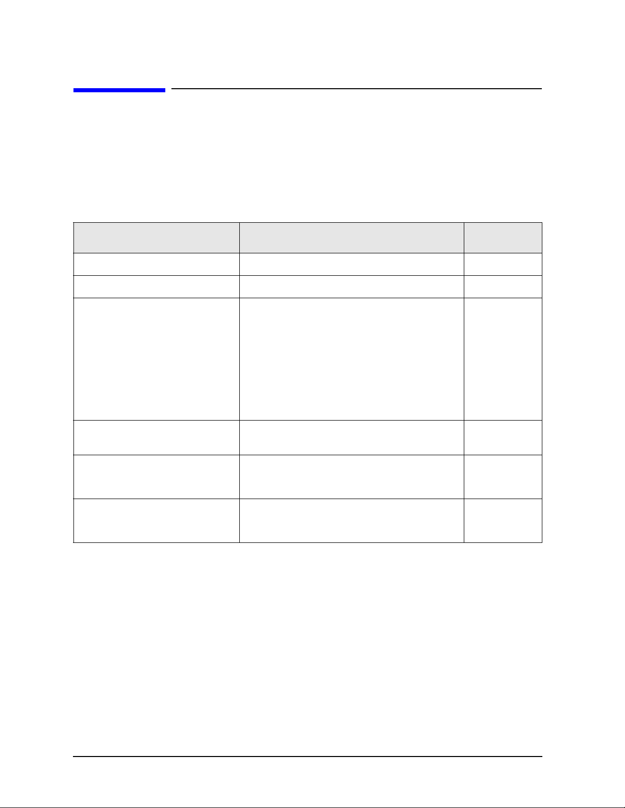
Information in This Chapter
Information in This Chapter
This chapter provides safety information that will help protect you and your network analyzer. It also
contains information that is required by various government regulatory agencies.
Section Title Summary of Content Start Page
Safety Symbols
General Safety Considerations
Electrostatic Discharge Protection
Regulatory Information
Descriptions of CAUTION and WARNING
symbols used throughout this manual.
A list of safety points to consider when servicing
your network analyzer.
A discussion of electrostatic discharge (ESD) and
related recommendations and requirements for ESD
protection.
Definitions of instrument markings.
Instructions for disposing of the analyzer’s lithium
battery.
Page 1-3
Page 1-3
Page 1-5
Page 1-6
1-2 N9927-90003
Page 11

FieldFox Analyzer Safety and Regulatory Information
Safety Symbols
Safety Symbols
The following safety symbols are used throughout this manual. Familiarize yourself with each of the
symbols and its meaning before operating this instrument.
CAUTION Caution denotes a hazard. It calls attention to a procedure that, if not correctly performed
or adhered to, could result in damage to or destruction of the instrument. Do not proceed
beyond a caution note until the indicated conditions are fully understood and met.
WARNING Warning denotes a hazard. It calls attention to a procedure which, if not correctly
performed or adhered to, could result in injury or loss of life. Do not proceed beyond
a warning note until the indicated conditions are fully understood and met.
General Safety Considerations
Safety Earth Ground
WARNING This is a Safety Class I product (provided with a protective earthing ground
incorporated in the power cord). The mains plug shall only be inserted in a socket
outlet provided with a protective earth contact. Any interruption of the protective
conductor, inside or outside of the instrument, will make the instrument dangerous.
Intentional interruption is prohibited.
CAUTION Always use the three-prong AC power cord supplied with this product. Failure to ensure
adequate grounding by not using this cord may cause produ ct damage.
N9927-90003
1-3
Page 12

Safety and Regulatory Information FieldFox Analyzer
General Safety Considerations
Before Applying Power
WARNING If this product is not used as specified, the protection provided by the equipment
could be impaired. This product must be used in a normal condition (in which all
means for protection are intact) only.
CAUTION This product is designed for use in Installation Category II and Pollution Degree 2 per
IEC 61010-1:2001 and 664 respectively.
CAUTION The measuring terminals on this instrument are designed to be used with external signals
described in Measurement Category I, but NOT with external signals described in
Categories II, III, and IV. The input of this instrument cannot be connected to the mains.
Servicing
WARNING These servicing instructions are for use by qualified personnel only. To avoid
electrical shock, do not perform any servicing unless you are qualified to do so.
WARNING Danger of explosion if battery is incorrectly replaced. Replace only with the same or
equivalent type recommended. Discard used batteries according to local ordinances
and/or manufacturer’s instructions.
WARNING No operator serviceable parts inside. Refer servicing to qualified personnel. To
prevent electrical shock, do not remove covers.
WARNING For continued protection against fire hazard, replace line fuse only with same type
and rating. The use of other fuses or material is prohibited.
WARNING The detachable power cord is the instrument disconnecting device. It disconnects
the mains circuits from the mains supply before other parts of the instrument. The
front panel switch is only a standby switch and is not a LINE switch (disconnecting
device).
1-4 N9927-90003
Page 13

FieldFox Analyzer Safety and Regulatory Information
Electrostatic Discharge Protection
Electrostatic Discharge Protection
Protection against electrostatic discharge (ESD) is essential while removing assemblies from or
connecting cables to the network analyzer. Static electricity can build up on your body and can easily
damage sensitive internal circuit elements when discharged. Static discharges too small to be felt can
cause permanent damage. To prevent damage to the instrument:
• always have a grounded, conductive table mat in front of your test equipment.
• always wear a grounded wrist strap, connected to a grounded conductive table mat, having a 1 MΩ
resistor in series with it, when handling components and assemblies or when making connections.
• always wear a heel strap when working in an area with a conductive floor. If you are uncertain about
the conductivity of your floor, wear a heel strap.
• always ground yourself before you clean, inspect, or make a connection to a static-sensitive device or
test port. You can, for example , gr asp the grounded outer shell of the test port or cable connector
briefly.
• always ground the center conductor of a test cable before making a connection to the analyzer test
port or other static-sensitive device. This can be done as follows:
1. Connect a short (from your calibration kit) to one end of the cable to short the center conductor to
the outer conductor.
2. While wearing a grounded wrist strap, grasp the outer shell of the cable connector.
3. Connect the other end of the cable to the test port and remove the short from the cable.
Figure 1-1 shows a typical ESD protection setup using a grounded mat and wrist strap. Refer to “ESD
Supplies” on page 6-14 for part numbers.
Figure 1-1 ESD Protection Setup
N9927-90003
1-5
Page 14

Safety and Regulatory Information FieldFox Analyzer
ICES/NMB-001
Regulatory Information
Regulatory Information
This section contains information that is required by various government regulatory agencies.
Instrument Markings
The instruction documentation symbol. The product is marked with this symbol
when it is necessary for the user to refer to the instructions in the documentation.
The CE mark is a registered trademark of the European Community. (If
accompanied by a year, it is when the design was proven.)
The CSA mark is a registered trademark of the Canadian Standards Association.
This is a marking to indicate product compliance with the Canadian
Interference-Causing Equipment Standard (ICES-001).
This is a symbol of an Industrial Scientific and Medical Group 1 Class A
product.
This is a required mark signifying compliance with an EMC requirement. The
C-Tick mark is a registered trademark of the Australian Spectrum Management
Agency.
This product complies with the WEEE Directive (2002/96/EC) marking requirements.
The affixed label indicates that you must not discard this electrical/ electronic product in
domestic household waste.
Product Category: With reference to the equipment types in the WEEE Directive Annex
I, this product is classed as a “Monitoring and Control instrumentation” product.
Do not dispose in domestic household waste.
To return unwanted products, contact your local Agilent office, or see
http://www.agilent.com/environment/product/ for more information.
1-6 N9927-90003
Page 15

FieldFox Analyzer Safety and Regulatory Information
Regulatory Information
Battery Disposal
If the either the primary power battery, or the RTC (real time clock) battery (on the A3 front panel
interface board) needs to be disposed of, dispose of it in accordance with your country’s requirements. If
required, you may return the battery to Agilent Technologies for disposal. Refer to “Contacting Agilent”
on page 2-9 for assistance.
For instructions on removing and replacing the primary power battery, refer to “Removing and
Replacing the Main Battery” on page 7-6.
For instructions on removing and replacing the RTC (real time clock) battery located on the A3 front
panel interface board, refer to “Replacing the A3 Front Panel Interface Board (FPIB)” on page 7-25.
N9927-90003
1-7
Page 16

Safety and Regulatory Information FieldFox Analyzer
Regulatory Information
1-8 N9927-90003
Page 17

2 General Product Information
N9927-90003 2-1
Page 18

General Product Information FieldFox Analyzer
Information in This Chapter
Information in This Chapter
Section Title Summary of Content Start Page
Cleaning instructions for the external surfaces of
Maintenance
your analyzer.
Page 2-2
Information about electrical maintenance of your
analyzer.
Analyzer Models
Analyzer Options
Agilent Support, Services, and
Assistance
A list of the models available for the microwave
network analyzers.
A list of the options available for the microwave
network analyzers.
The Internet address (URL) for Agilent assistance.
Service and support options available.
Calibration options available.
Important information about shipping your
analyzer to Agilent for service or repair.
Page 2-3
Page 2-4
Page 2-8
Maintenance
WARNING To prevent electrical shock, disconnect the analyzer from the mains source before
cleaning. Use a dry cloth or one slightly dampened with water to clean the external
case parts. Do not attempt to clean internally.
Physical Maintenance
Clean the analyzer case using a dry or slightly damp cloth only.
Electrical Maintenance
Refer to “Contacting Agilent” on page 2-9 and to Chapter 3 , “Tests and Adjustments.”
2-2 N9927-90003
Page 19

FieldFox Analyzer General Product Information
Analyzer Models
Analyzer Models
Max Freq (GHz) N991x Combo N992x VNA N993x SA
4 N9913A X X
6.5 N9914A X X
9 N9915A N9925A N9935A
14 N9916A N9926A N9936A
18 N9917A N9927A N9937A
26.5 N9918A N9928A N9938A
N9927-90003 2-3
Page 20

General Product Information FieldFox Analyzer
Analyzer Options
Analyzer Options
Below is a list of options that effect hardware for the FieldFox at the time of initial product release.
Additional options will be added as product features are enhanced. Go to
www.agilent.com/find/fieldfox2 for information on currently available upgrade options.
Table 2-1. Options
Option Description N991x Combo N992x VNA N993x SA
010 VNA Time Domain Available Available −
030 Remote Control Capability Available Available Available
100 3.5 mm APC Connectors -- -- N9938A
112 QuickCal Available Available −
210 VNA Transmission/Reflection Available
211 VNA Full 2-Port S-Parameters Available Available −
220 Tracking Generator See 210 − Available
233 Spectrum Analyzer Available −
235 Preamplifier Available − Available
236 Interference Analyzer and Spectrogram Available − Available
238 Spectrum Analyzer Time Gating Available − Available
302 USB Power Sensor Support Available Available Available
305 Cable and Antenna Analyzer Included in
Base
307 GPS Receiver Available Available Available
308 Vector Voltmeter Available Available −
309 DC Bias Variab le- Voltage Source Available Available Available
310 Built-In Power Meter Available Available Available
320 Reflection Measurements (RL, VSWR) Included in
Base
Base Model −
Base Model
Available −
− Available
2-4 N9927-90003
Page 21

FieldFox Analyzer General Product Information
Analyzer Options
Option Descriptions
Option 010, Vector Network Analyzer Time Domain
With Option 010 or time domain, FieldFox computes the inverse Fourier transform of the
frequency-domain data to display reflection or transmission coefficients versus time. Time domain
gating can be used to remove unwanted responses such as connector mismatch or cable discontinuities,
and the results can be displayed in either time or frequency domain.
• Fully error-corrected time domain reflection or transmission response
• Gating available to remove unwanted responses
• View time and frequency domain data simultaneously
• Transform frequency domain to the time domain or time domain to the frequency domain
Option 030, Remote Control Capability
Option 030 adds remote control capability to FieldFox for iDevices.
• User must supply iPad, iPhone, or iPod.
• User must download free FieldFox app from App store.
Option 100, 3.5 mm APC Connectors
Option 100 provides 3.5 mm input and output connectors.
Available on N9938A model only (26.5 GHz) at initial purchase.
Option 112, QuickCal
Option 112 provides a calib ratio n th at is performed automatically using calibrati on standards that are
built-in to the FieldFox. Calibration standards are automatically switched in as needed. QuickCal is ideal
for making quick DTF and cable loss measurements without taking the time to perform a full O,S,L Cal.
Option 210, Vector Network Analyzer Transmission/Reflection
A base combination analyzer includes a cable and antenna analyzer.
Available on N9991x Combination models. Base option available for N9992x models only.
Option 210 adds:
• A vector network analyzer mode with transmission/reflection or S21 and S11 measurements, both
magnitude and phase. Available calibrations are CalReady, one-port OSL, response and enhanced
response.
• Insertion loss measurement to the base cable and antenna analyzer or CAT mode.
• 2-port transmission measurement to the vector voltmeter mode, available as Option 308.
• Tracking capability to the spectrum analyzer independent source, available as Option 233 (source and
spectrum analyzer set to sweep a frequency range, in sync)
N9927-90003 2-5
Page 22

General Product Information FieldFox Analyzer
Analyzer Options
Option 211, Vector Network Analyzer Full 2-Port S Parameters
For the N991x Combination models of FireFox, Option 211 provides transmission/reflection or S21 and
S11 measurement capabilities, along with one-port and enhanced response calibrations. Additionally for
the N991x Combination models and the N992x VNA models, Option 211 provides all four S-parameters
- forward and reverse (S11, S21, S12, S22), and full 2-port calibration. Full 2-port cal ibration is the most
accurate calibration available with FieldFox network analyzers.
Option 211 also adds A/B and B/A measurement capabilities to the vector voltmeter mode, available as
Option 308.
• Adds reverse measurements to the VNA
• All four S-parameters (S21, S11, S12, S22), magnitude and phase
Option 220, Tracking Generator - Full Band
Option 220 allows you to easily make accurate scalar stimulus/response measurements on active and
passive components, cables, connectors and antennas. The full-band tracking generator source can also
be decoupled to act as a stand-alone source that can be used to stimulate an active or passive component,
optionally using the spectrum analyzer for measurement.
Option 233, Spectrum Analyzer
Option 233 adds a high performance, full-band spectrum analyzer including four traces, different
detector types, radio standard selection and flexible limit lines. The option offers channel power
measurements, AM/FM tune and listen, field strength measurements, antenna factors and frequency
counter markers. Also included is a full-band tracking generator.
Option 235, Preamplifier for Spectrum Analyzer
Option 235 increases the spectrum analyzer sensitivity, reducing the DANL to -155 dBm.
Option 233 is prerequisite.
Option 236, Interface Analyzer and Spectrogram
Option 236 provides quick and accurate identification of interfering signals using the spectrogram or
waterfall display. Record and playback allows signal capture and offline processing.
Option 233 is prerequisite.
Option 238, Spectrum Analyzer Time Gating
• Adds FFT.
• Gate sources: External, RF Burst, and Video.
• Option 233 is a prerequisite for Option 238
2-6 N9927-90003
Page 23

FieldFox Analyzer General Product Information
Analyzer Options
Option 302, External USB Power Sensor Support
Option 302 allows the use of an external USB controllable power sensor.
All Agilent U2000x Series USB power sensors are supported with FieldFox.
Visit: www.agilent.com/find/u2000 for an up-to-date listing.
Option 305, Cable and Antenna Analyzer
Option 305 provides fast and accurate diagnosis of cables, connectors, and antennas with DTF (dB,
linear, VSWR), return loss and DTF, 1-port cable loss, 2-port insertion loss, and CalReady.
Option 307, GPS Receiver
Option 307 enables the built-in GPS receiver. Requires a GPS antenna such as N9910X-825.
Option 308, Vector Voltmeter (VVM)
Option 308 includes S11 or one-port cable trimming.
Option 309, DC Bias Variable-Voltage Source
Option 309 adds an integrated built-in variable voltage DC bias source to the FieldFox analyzer. The
source provides 1 to 32 VDC with maximum current of 650 mA and 7 watts maximum power. The DC
bias source can provide DC power to amplifiers under test and bias tower mounted amplifiers (TMA)
when engineers need to sweep through the TMA to reach the antenna. The bias-tee is available
separately. The DC output has an SMB (m) connector.
Option 310, Built-In Power Meter
Option 310 provides the functionality to make user-definable channel power measurements such as
transmitter output power. By leveraging InstAlign technology, FieldFox is able to make very accurate
channel power measurements.
Option 320, Reflection Measurements (Return Loss, VSWR, and Scalar Measurement)
Measurement of VSWR and return loss can be made on active and passive devices, cables, connectors
and antennas. Option 220 is prerequisite.
N9927-90003 2-7
Page 24

General Product Information FieldFox Analyzer
Agilent Support, Services, and Assistance
Agilent Support, Services, and Assistance
Information on the following topics is included in this section.
• “Service and Support Options”
• “Calibration Options”
• “Contacting Agilent”
• “Shipping Your Analyzer to Agilent for Service or Repair”
Service and Support Options
The analyzer’s standard warranty is a one-year return to Agilent Technologies service warranty.
NOTE There are other repair and calibration options available from Agilent Technologies.
Contact Agilent for additional information on available service agreements for this
product. Refer to “Contacting Agilent” on page 2-9.
Calibration Options
Commercial Calibration Certificate with Test Data
A complete set of measurements that test the analyzer to the manufacturer’s published specifications. It
includes a calibration label, a calibration certificate, and the corresponding calibration data report. This
calibration conforms to ISO 9001.
ISO 17025 Standards Compliant Calibration
A complete set of measurements that test the analyzer to the manufacturer’s published specifications. It
includes a calibration label, an ISO 17025 calibration certificate, and the corresponding calibration data,
measurement uncertainties, and guardbands on all customer specifications. This calibration conforms to
ISO 17025 and ISO 9001.
This calibration option is available at the time of purchase or can be obtained later by sending your
analyzer to Agilent for calibration. Refer to “Shipping Your Analyzer to Agilent for Service or Repair”.
ANSI Z540 Standards Compliant Calibration
A complete set of measurements that test the analyzer to the manufacturer’s published specifications. It
includes both pre- and post-adjustment data with measurement uncertainty information compliant to the
ANSI/NCSL Z540 standard.
This calibration option is available at the time of purchase or can be obtained later by sending your
analyzer to Agilent for calibration. Refer to “Shipping Your Analyzer to Agilent for Service or Repair”.
2-8 N9927-90003
Page 25

FieldFox Analyzer General Product Information
Agilent Support, Services, and Assistance
Contacting Agilent
Assistance with test and measurements needs and information on finding a local Agilent office are
available on the Web at:
http://www.agilent.com/find/assist
If you do not have access to the Internet, please contact your Agilent field engineer.
NOTE In any correspondence or telephone conversation, refer to the Agilent product by its
model number and full serial number. With this information, the Agilent representative
can determine whether your product is still within its warranty period.
Shipping Your Analyzer to Agilent for Service or Repair
IMPORTANTAgilent Technologies reserves the right to reformat or replace the internal flash drive in
your analyzer as part of its repair. This will erase all user information stored on the drive.
It is imperative, therefore, that you make a backup copy of your critical test data located
on the analyzer’s flash drive before shipping it to Agilent for repair.
If you wish to send your network analyzer to Agilent Technologies for service or repair:
• Include a complete description of the service requested or of the failure and a description of any
failed test and any error message.
• Ship the analyzer using the original or comparable antistatic packaging materials.
• Contact Agilent for instructions on where to ship your analyzer. Refer to “Contacting Agilent” on
page 2-9.
N9927-90003 2-9
Page 26

General Product Information FieldFox Analyzer
Agilent Support, Services, and Assistance
2-10 N9927-90003
Page 27

3 Tests and Adjustments
N9927-90003 3-1
Page 28

Tests and Adjustments FieldFox Analyzer
Information in This Chapter
Information in This Chapter
This chapter contains procedures to help you check, verify, and adjust your FieldFox analyzer.
• The checks verify the operation of the assemblies in your analyzer.
• The adjustments allow you to tune your analyzer for maximum response.
NOTE The Agilent N7841A software package is required to test and adjust your analyzer. This
software package must be purchased separately. It can be downloaded from the Internet
and a license purchased on-line, or it can be ordered on a CD-ROM. Go to
www.agilent.com/find/calibrationsoftware for further information. The help file for the
N7841A software package is also available at this URL.
Section Title Summary of Content Start Page
Items to consider or procedures to perform before testing is
begun:
•
Verify the operating environment.
Before You Begin
Service Test Equipment
Before Returning an
Instrument to a Customer
Operational Check
Performance Tests
(Agilent N7841A
Software Package)
Adjustments (Agilent
N7841A Software
Package)
a
1. The Agilent N7841A software package must be purchased separately. Go to
www.agilent.com/find/calibrationsoftware for information.
1
• Protect Against Electrostatic Discharge (ESD)
• Allow the Analyzer to Warm Up
• Review the Principles of Connector Care
A list of additional equipment recommended for servicing the
FieldFox analyzer.
A list of things to do before returning an instrument to a
customer after servicing is completed.
An operation check that should be performed before returning
an instrument to a customer.
A list of performance tests included in the Agilent N7841A
software package.
A list of adjustments included in the Agilent N7841A software
package.
Page 3-3
Page 3-5
Page 3-6
Page 3-7
Page 3-9
Page 3-10
3-2 N9927-90003
Page 29

FieldFox Analyzer Tests and Adjustments
Before You Begin
Before You Begin
Before checking, verifying, or adjusting the analyzer, refer to the following paragraphs to:
• Make sure the operating environment is within 19 to 27 °C and 5 to 95% humidity.
• Make sure that proper electrostatic discharge (ESD) protection is provided.
• Review the principles of connector care.
Protect Against Electrostatic Discharge (ESD)
This is important. If not properly protected against, electrostatic discharge can seriously damage your
analyzer, resulting in costly repair.
CAUTION To reduce the chance of electrostatic discharge, follow all of the recommendations
outlined in “Electrostatic Discharge Protection” on page 1-5, for all of the procedures in
this chapter.
Allow the Analyzer to Warm Up
Before testing or adjusting the FieldFox analyzer, allow it to warm up as described under “DUT
Warmup” in the “Getting Started” section of the N7841A help file.
N9927-90003 3-3
Page 30

Tests and Adjustments FieldFox Analyzer
Before You Begin
Review the Principles of Connector Care
Proper connector care and connection techniques are critical for accurate and repeatable measurements.
Refer to Table 3-1 for tips on connector care.
Prior to making connections to your analyzer, carefully review the information about inspecting,
cleaning, and gaging connectors. Refer to the calibration kit documentation for detailed connector care
information.
For course numbers about additional connector care instruction, contact Agilent Technologies. Refer to
“Contacting Agilent” on page 2-9.
Table 3-1Connector Care Quick Reference Guide
Handling and Storage
Do • Keep connectors clean Do Not • Touch mating-plane surfaces
• Extend sleeve or connector nut • Set connectors contact-end down
• Use plastic end-caps during storage • Store connectors or adapters loose
Visual Inspection
Do • Inspect all connectors carefully Do Not • Use a damaged connector - ever
• Look for metal particles, scratches, and
dents
Connector Cleaning
Do • Try compressed air first Do Not • Use any abrasives
• Use isopropyl alcohol
• Clean connector threads
Do • Clean and zero the gage before use Do Not • Use an out-of-specification connector
• Use the correct gage type
• Use correct end of calibration block
• Gage all connectors before first use
Do • Align connectors carefully Do Not • Apply bending force to connection
• Make preliminary connection contact
lightly
• Turn only the connector nut • Twist or screw any connection
• Use a torque wrench for final connection • Tighten past torque wrench “break”
1. Cleaning connectors with alcohol shall only be done with the instrument’s power cord removed, and in
a well-ventilated area. Allow all residual alcohol moisture to evaporate, and the fumes to dissipate prior
to energizing the instrument.
1
Gaging Connectors
Making Connections
• Get liquid into plastic support beads
• Over tighten preliminary connection
point
3-4 N9927-90003
Page 31

FieldFox Analyzer Tests and Adjustments
Service Test Equipment
Service Test Equipment
The test equipment required for the TME based N7841A test and adjustment software is listed in the
N7841A help file.
The following additional test equipment is recommended when servicing the FieldFox analyzer:
• Main Battery—Required if the analyzer is returned for service without a battery. Refer to Table on
page 13 for part numbers.
• USB flash drive—Used for firmware upgrades, option installation, etc. Also known as USB memory
stick. Must be 128 MB or larger.
• Small, free-standing fan—Used to cool the analyzer if internal temperature is too high. See “DUT
Warmup” in the “Getting Started” section of the N7841A help file for usage instructions. Generic
small office fan of approximately six inches in diameter is sufficient.
• Cal kit—Cal kit compatible with port connectors.
• Mini SD flash card—Required to re-load firmware onto the A6 SOM board. A “mini” sized Secure
Digital (SD) flash memory card is between “standard” and “micro” sizes. The memory size must be
at least 64 MB and not greater than 2 GB. This card is not available from Agilent. To identify a
supplier, search the Web for “mini sd card”.
• Stereo headphones or ear buds—May be used to troubleshoot sound output if there is a problem
with the internal speaker.
N9927-90003 3-5
Page 32

Tests and Adjustments FieldFox Analyzer
Before Returning an Instrument to a Customer
Before Returning an Instrument to a Customer
When finished servicing an FieldFox analyzer, perform the following before returning the unit to the
customer:
• Set the Display Colors to Indoor and the display Brightness to 80% via
System (7) > Preferences > Preferences, etc.
• Perform an Operational Check as described in the following section.
• Connect and disconnect the external battery charger while the FieldFox is operating and confirm that
the power cord icon is displayed appropriately at the top of the display.
• Charge the battery to 80% or higher.
• Press
System > System Configuration > More > Date and Time
See http://na.tm.agilent.com/fieldfox/service/rtc_info.htm
for restrictions and details for setting time and date.
.
3-6 N9927-90003
Page 33

FieldFox Analyzer Tests and Adjustments
Operational Check
Operational Check
This operational check exercises only very basic measurement functionality.
Required Equipment
A short compatible with the port connector type on the FieldFox.
A load compatible with the port connector type on the FieldFox.
(Both are typically available in a compatible cal kit.)
Procedure
1. Press
Preset > Preset (Factory)
. The top-left corner of the FieldFox display indicates the active
measurement type following the preset.
2. If the active measurement is SA then skip to step 5 below.
If the active measurement is S11 or CAT then complete this step below:
• Connect a short to Port 1.
• Displayed trace should be within ± 4 dB of zero.
• Connect a load to Port 1.
• Displayed trace should approximate the value of load, typically it will be below −20 dB (20 dB
for CAT mode).
3. Press
Mode
. If NA is not available, skip to step 5 below.
If NA is available then continue at step 4 below.
4. Press
then press
Measure (1)
. If S22 is not available then skip to step 5 below.
NA
If S22 is available then continue this step below:
• Connect a short to Port 2.
• Press
S22
• Displayed trace should be within ± 4 dB of zero.
• Connect a load to Port 2
• Displayed trace should approximate the value of load, typically it will be below −20 dB.
N9927-90003 3-7
Page 34

Tests and Adjustments FieldFox Analyzer
Operational Check
5. Press
Mode
. If SA is available then continue below, otherwise the operational check is complete.
• For this step Port 2 should be unconnected or connected to a short or load.
• Press
SA
.
• The measurement trace should be below the following limits:
Up to 4 GHz: limit = −45 dBm
Up to 6.5 GHz: limit = −42 dBm
Up to 9 GHz: limit = −39 dBm
Up to 14 GHz: limit = −33 dBm
Up to 18 GHz: limit = −28 dBm
Up to 26.5 GHz: limit = −18 dBm
• The general slope of the trace should trend upward. A flat trace indicates an uncalibrated
condition that requires adjustments.
• If a segment of the trace is offset by more than 10 dBm from the general slope of the trace, this
indicates a hardware failure that requires service.
3-8 N9927-90003
Page 35

FieldFox Analyzer Tests and Adjustments
Performance Tests (Agilent N7841A Software Package)
Performance Tests (Agilent N7841A Software Package)
The performance tests section of the Agilent N7841A software package verifies the electrical
performance of your FieldFox analyzer. The software automatically configures your analyzer to execute
the performance tests.
The N7841A software package is not included with the analyzer; it must be ordered separately. It can be
downloaded from the Internet and a license purchased on-line, or it can be ordered on a CD-ROM. Go to
www.agilent.com/find/calibrationsoftware for further information.
There are seventeen performance verification tests that test for the general functionality of the analyzer
and the SA (spectrum analyzer) specific functionality.
Total test time may be up to 3 hours depending upon model and options installed.
Details for these tests and recommended troubleshooting information can be found in the N7841A help
file.
Performance Verification Tests
• Error Terms Test — Note that the associated adjustment should be performed every 12 months.
See “Adjustments (Agilent N7841A Software Package)” on page 3-10.
• Frequency Accuracy Test
• Displayed Average Noise Level Test
• Frequency Readout and Count Accuracy Test
• IF Frequency Response Test
• Noise Sidebands Test
• Total Abs Amp Accy Low Freq Test
• Total Abs Amp Accy Low Freq Preamp On Test
• Total Abs Amp Accy High Freq Test
• Total Abs Amp Accy High Freq Preamp On Te st
• Third Order Intermodulation Distortion Test
• Absolute Amplitude Accuracy Test
• Dynamic Accuracy Test
• System Dynamic Range Test
• Receiver Compression
• Trace Noise Test
• GPS Function Test
• DC Bias Source Test
• Source Power Test
N9927-90003 3-9
Page 36

Tests and Adjustments FieldFox Analyzer
Adjustments (Agilent N7841A Software Package)
Adjustments (Agilent N7841A Software Package)
The adjustments section of the Agilent N7841A software package may be used to fine-tune your
analyzer.
The N7841A software package is not included with the analyzer; it must be ordered separately. It can be
downloaded from the Internet and a license purchased on-line, or it can be ordered on a CD-ROM. Go to
www.agilent.com/find/calibrationsoftware for further information.
There are nine adjustments that are used to adjust the general functions of the analyzer and the SA
(spectrum analyzer) specific functions.
Total adjustment time may be up to 5 hours depending upon models and options installed.
If multiple adjustments are to be performed, perform them in the order listed by the N7841A software.
Details for these adjustments, and recommended troubleshooting information, can be found in the
N7841A help file.
Adjustments
• Max Power and IF Overload Adjustment
• Source Power Adjustment
• Error Terms Adjustment— See “Performance Tests (Agilent N7841A Software Package)” on page
3-9. This adjustment should be performed every 12 months. It refreshes the definition of the preset
calibration.
• Frequency Accuracy Adjustment
• LO Feedthru Adjustment
• Absolute Amplitude Adjustment
• Frequency Response Adjustment
• Attenuator Slope Adjustment
• IF Frequency Response Adjustment
3-10 N9927-90003
Page 37

4 Troubleshooting
N9927-90003 4-1
Page 38
Troubleshooting FieldFox Analyzer
Information in This Chapter
Information in This Chapter
The information in this chapter helps you:
• Identify the portion of the analyzer at fault.
• Locate the specific troubleshooting procedure to identify the assembly or peripheral at fault.
The sections in this chapter are arranged in a logical troubleshooting order. The following table lists the
sections and a brief summary of what to look for in that section.
Section Title Summary of Content Start Page
Getting Started with Troubleshooting A starting point to begin troubleshooting. Page 4-4
Power Up Troubleshooting Power-up problems: Page 4-6
Problems with the front panel assemblies of the
analyzer.
Front Panel Group Troubleshooting
Measurement Group Troubleshooting
• Problems in NA Mode
• Problems in SA Mode
• Does the display appear correct?
• Is the sound working?
• Do the front panel keys function properly?
• Does the front panel USB and SD card
connection function properly?
Problems with the measurement group assemblies
of the analyzer.
VNA Specific Troubleshooting
• Checking the A, B, R1, and R2 signals
SA Specific Troubleshooting
• Checking source power
Page 4-7
Page 4-9
Page 4-9
Page 4-11
4-2 N9927-90003
Page 39

FieldFox Analyzer Troubleshooting
Protect Against Electrostatic Discharge (ESD)
Protect Against Electrostatic Discharge (ESD)
This is important. If not properly protected against, electrostatic discharge can seriously damage your
analyzer, resulting in costly repair.
CAUTION To reduce the chance of electrostatic discharge, follow all of the recommendations
outlined in “Electrostatic Discharge Protection” on page 1-5, for all of the procedures in
this chapter.
Assembly Replacement Sequence
After identifying the problem requiring an assembly to be replaced, follow these steps:
Step 1. Order a replacement assembly. Refer to Chapter 6 , “Replaceable Parts.”
Step 2. Replace the faulty assembly and determine what adjustments are necessary.
Refer to Chapter 7 , “Repair and Replacement Procedures.”
Step 3. Perform the necessary adjustments. Refer to Chapter 3 , “Tests and Adjustments.”
Step 4. Perform the necessary performance tests. Refer to Chapter 3 , “Tests and Adjustments.”
N9927-90003 4-3
Page 40

Troubleshooting FieldFox Analyzer
Getting Started with Troubleshooting
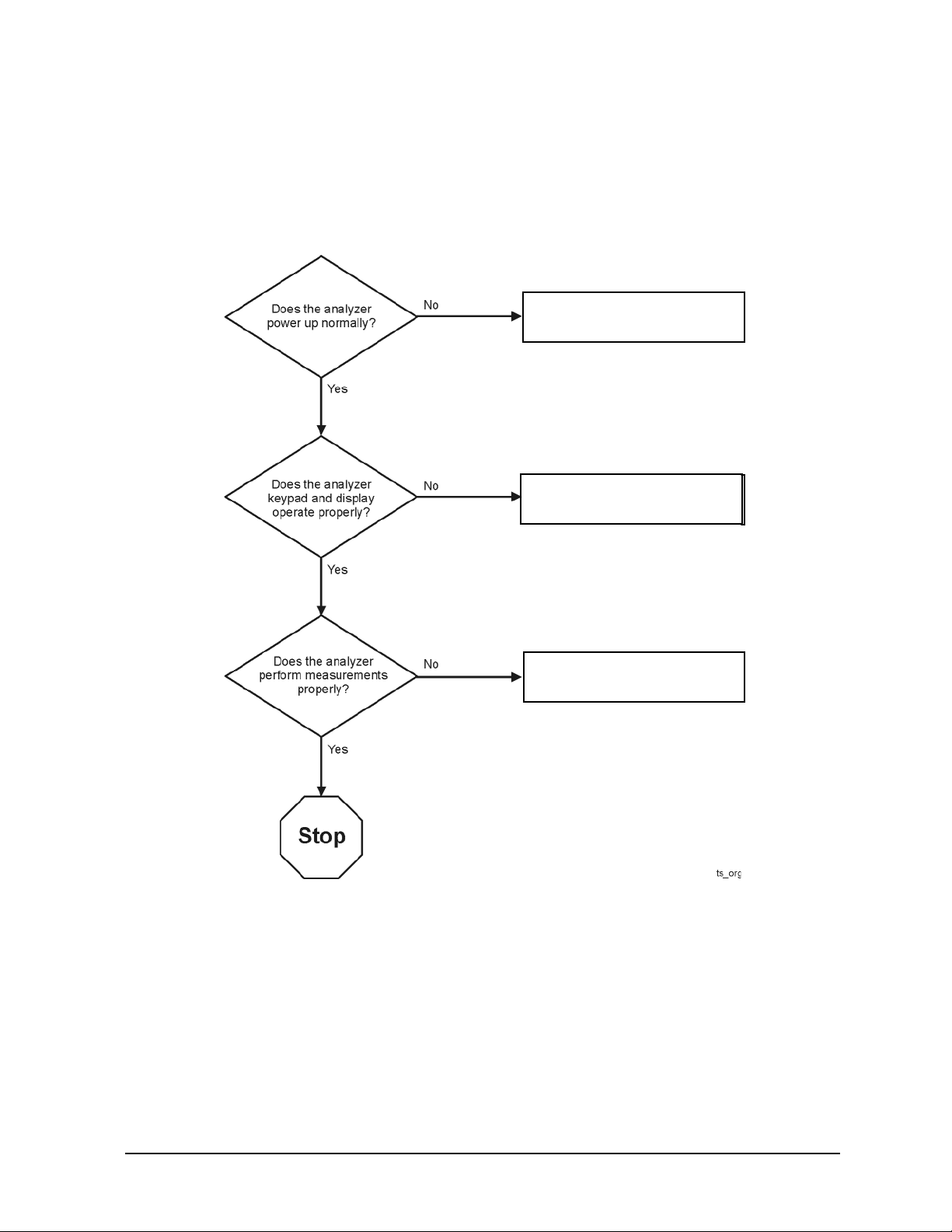
Getting Started with Troubleshooting
Where you begin troubleshooting depends upon the symptoms of the failure. If a performance test or
adjustment fails, refer to the troubleshooting recommendations in the N7841A TME Help. For
other failures, start by checking the basics as outlined in the following section. Also review the flowchart
in Figure 4-1 on page 4-5. You should then be able to determine where in the troubleshooting procedure
to begin, to locate the failed assembly.
Check the Basics
A problem can often be solved by repeating the procedure you were following when the problem
occurred. Before calling Agilent Technologies or returning the instrument for service, please perform the
following checks:
1. Does the analyzer have power available? It is recommended that the battery is installed and the AC
power adapter is also connected.
2. Does the analyzer turn On and Off when the On/Off Button is pressed? When the unit is on, the green
LED below the button should light.
3. Does the analyzer power up normally into its default mode? If not, see “Power Up Troubleshooting”
on page 4-6.
4. If other equipment, cables, and connectors are being used with th e analyzer, make sure they are clean,
connected properly and operating correctly.
5. Review the procedure for the measurement being performed when the problem appeared. Are all the
settings correct? If not, correct them.
6. If the analyzer is not functioning as expected, return it to a known state by pressing the
7. If the problem is thought to be due to firmware, check to see if the instrument has the latest firmware
before starting the troubleshooting procedure. Refer to “Firmware Upgrades” in Chapter 8 for
instructions.
Preset
key.
4-4 N9927-90003
Page 41
FieldFox Analyzer Troubleshooting
Go to “Front Panel Group
Troubleshooting” on page 4-7
.
Go to “Measurement Group
Troubleshooting” on page 4-9
.
Go to “Power Up Troubleshooting”
on page 4-6
.
Go to “Power Up Troubleshooting”
on page 4-6
.
Getting Started with Troubleshooting
Troubleshooting Organization
Follow the flowgraph in Figure 4-1 to help direct you to the correct section for troubleshooting the
analyzer.
Figure 4-1 Troubleshooting Organization Flowchart
N9927-90003 4-5
Page 42

Troubleshooting FieldFox Analyzer
Power Up Troubleshooting
Power Up Troubleshooting
If the display is operational but the unit does not boot up successfully:
• Make sure there is sufficient power for the unit to operate.
• Try re-installing firmware using the firmware upgrade process described in Chapter 8.
• Assume corrupted firmware on the A6 SOM board, follow the “Install Firmware from SD Card” near
the end of Chapter 7.
If the display is dark but the unit may have booted successfully:
• Wait for three minutes to make sure the boot process has completed, then press any front panel key.
If the boot process has completed successfully, the keypad will flash when a key is pressed.
4-6 N9927-90003
Page 43

FieldFox Analyzer Troubleshooting
Front Panel Group Troubleshooting
Front Panel Group Troubleshooting
Checking Display Brightness and Sound
If the display is dark (no backlight)
• Press
• Select
• Select
• Use the arrow keys to select
System, 7
Preferences
Preferences
Brightness
, press
Edit
, then use the arrow keys to change the display
brightness.
• If the A2 LCD display assembly is determined to be faulty, replace it. Refer to “Replacing the A2
LCD, the LCD Shield, and LCD Cables” on page 7-23.
• Use the arrow keys to select
Volume
, press
Edit
, then use the arrow keys to change the volume. A
beep should occur each time the value is changed.
• Plug headphones into the unit if there is no sound from the internal speaker. The internal speaker is
disabled when headphones are plugged in.
• If the audio is still not heard, the System board may be faulty. Refer to “Replac ing the A5 System
Board” on page 7-35.
Checking the Front Panel Keys
To check the front panel keys, push each labeled key and compare with the specific functions.
• If all the key names are correct, then the front panel keypad is working.
• If some of the keys are not working, suspect a faulty keypad. To replace the keypad, refer to
“Replacing the Front Case (including the A1 Keypad)” on page 7-17.
• If none of the keys are working correctly, suspect a faulty A3 Front Panel Interface board. To replace
the A3 Front Panel Interface board, refer to “Replacing the A3 Front Panel Interface Board (FPIB)”
on page 7-25.
N9927-90003 4-7
Page 44

Troubleshooting FieldFox Analyzer
Front Panel Group Troubleshooting
USB and SD Card Slot Ports
To verify proper operation of any rear USB ports or SD Card port:
• Connect a known good USB flash memory or SD memory card.
• Wait 15 seconds for the analyzer to verify the device connection, and then check the operation of the
USB flash memory or SD memory card by performing the recall function
Save/Recall
• If the device performs correctly, the USB or SD Card port is functioning properly.
• If the device does not perform correctly, the System board is faulty. Refer to “Replacing the A5
System Board” on page 7-35
.
4-8 N9927-90003
Page 45

FieldFox Analyzer Troubleshooting
Measurement Group Troubleshooting
Measurement Group Troubleshooting
• Make sure the unit is warmed up for at least 30 minutes.
• Make sure the correct cal kit definition is being used; erase user data to force use of factory cal kit
definitions (see Chapter 8 for information on the “Erase User Data Utility”).
Problems in NA Mode
Every FieldFox contains a factory calibration that was performed at the port 1 and port 2 con nectors over
the entire frequency range of the FieldFox using a number of data points that allows reasonable
interpolation over the FieldFox frequency range.
This calibration, known as CalReady, allows you to immediately make accurate measurements for a
DUT that is connected directly at the test ports (PORT 1 and/or PORT 2). CalReady corrects
measurements when the FieldFox is turned ON, when Preset is pressed, and when a measurement is
created with no other correction in place.
If you are seeing a problem at Preset, perform the standard S-parameter test set troubleshooting
procedure, starting with the following procedure: “Checking the A, B, R1, and R2 Signals (NA Mode)”.
Checking the A, B, R1, and R2 Signals (NA Mode)
The first step is to verify that the A, B, R1, and R2 traces are present and that they are approximately
level:
• To access this:
1. Press
2. Select <Num of Traces>
3. Choose <x4>
4. Select <Trace 1>
5. Press
6. Choose <Advanced>
7. Select <A>
8. Repeat Steps 1, 4, 5, 6, and 7 for Receivers B, R1, and R2.
• Traces A, B, R1, and R2 are displayed in four separate data windows as shown in Figure 4-2..
Identifying discrepancies of the traces in these windows can help you to isolate the faulty assembly.
Trace, 3
Measure, 1
N9927-90003 4-9
Page 46

Troubleshooting FieldFox Analyzer
Measurement Group Troubleshooting
Figure 4-2. Typical Four Channel Display
• If all traces are present and are similar to the traces in Figure 4-2., then there are no major problems
with the analyzer's VNA measurement system. There may, however, be a minor failure in the
analyzer.
• To test further:
1. Go to Chapter 3 , “Tests and Adjustments,” and perform all the tests indicated in the N7841A
TME software.
2. If a problem still exists, contact Agilent. Refer to “Contacting Agilent” on page 2-9.
If any of the traces are not present, are noisy or distorted, or are at an incorrect level, then there is a
problem with the analyzer's measurement system and requires repair, contact Agilent. Refer to
“Contacting Agilent” on page 2-9.
4-10 N9927-90003
Page 47

FieldFox Analyzer Troubleshooting
Measurement Group Troubleshooting
Problems in SA Mode
The instruments unique signal analyzer blocks that are located on the A4, RF Board can be verified using
a signal source and a functioning spectrum analyzer capable of measuring a 33.75 MHz signal.
Verifying the 33.75 MHz I.F. Output
Set the signal source for a 1 GHz, CW signal at 0 dBm. If possible verify the signal source output
frequency and power level are correct by using a functioning spectrum analyzer as illustrated in Figure
4-3.
Figure 4-3. 1 GHz CW Signal
N9927-90003 4-11
Page 48
Troubleshooting FieldFox Analyzer
Measurement Group Troubleshooting
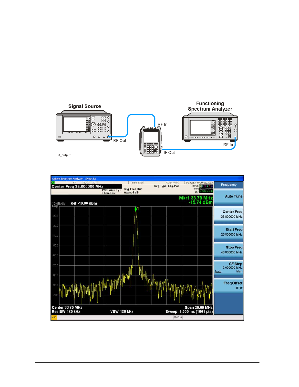
Inject that 1 GHz CW signal into the Port 2 SA RF Input connector on the instrument as illustrated in
Figure 4-4. From an instrument preset, tune the instrument to 1 GHz, 0 Span. Verify that the input
attenuator (Atten) is set to 10 dB. On the side of the instrument near the RPG tuning knob, there is a
spring door. Open that spring door and locate the IF Out SMB (m) connector. Connect one end of a test
cable to the IF Out connector on the side of the instrument. Connect the other end of the test cable to the
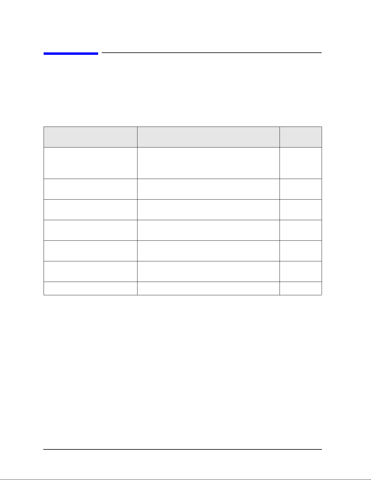
functioning spectrum analyzer. Tune the functioning spectrum analyzer to 33.75 MHz. The I.F. Out
signal level should measure 33.75 MHz at approximately -16 dBm as illustrated in Figure 4-5.
Figure 4-4. 33.75 MHz I.F. Output Test Setup
Figure 4-5. 33.75 MHz I.F. Output Signal
Since the input attenuator is set to 10 dB, there should be 6 dB of conversion loss from the RF input
connector to the I.F. Out connector.
4-12 N9927-90003
Page 49

FieldFox Analyzer Troubleshooting
Measurement Group Troubleshooting
NOTE The 1 GHz test signal was set to 0 dBm. The input attenuator on the analyzer was set to
10 dB. If the A4 R.F. Board had 0 dB of conversion loss, the 33.75 MHz I.F . output would
measure -10 dBm, but it measured -16 dBm because the A4, R.F. Board has 6 dB of
conversion loss.
If the input attenuator is changed from 10 dB to 0 dB, the signal will change by 10 dB to -6 dBm. You
can verify the input attenuator performance referencing the Table 4-1.
Table 4-1.
Input Attenuator Setting (dB) 33.75 MHz I.F. Output Level (dBm)
0 −6
5 −11
10 −16
15 −21
20 −26
25 −31
30 −36
If the 33.75 MHz I.F. Output level is not correct or the input attenuator performance is out of tolerance,
the most likely cause is the A4, R.F. Board.
N9927-90003 4-13
Page 50

Troubleshooting FieldFox Analyzer
Measurement Group Troubleshooting
4-14 N9927-90003
Page 51

5 Theory of Operation
N9927-90003 5-1
Page 52
Theory of Operation FieldFox Analyzer
Information in This Chapter
Information in This Chapter
This chapter provides a general description of the operating theory of the FieldFox analyzer.
• Theory of operation is explained to the assembly level only.
• Component-level circuit theory is not provided.
• Simplified block diagrams are included for each functiona l group.
Section Title Summary of Content Start Page
Analyzer System Operation A summary of the theory of operation for the analyzer.
A summary of the operation of the major functional
groups of the analyzer.
Front Panel Group Operation of the assemblies associated with the front
panel group of assemblies.
Measurement Group Operation of the assemblies associated with the
measurement group of assemblies.
Operation in Modes Description of the different operating modes and what
hardware is used in each mode.
Temperature Related Information Information about temperature sensors and how the
analyzer responds to temperature information gathered.
User Calibration in CAT, NA, and
VVM Modes
Firmware Related Information Information about firmware and firmware upgrades. page 5-28
Descriptions of one port and two port calibrations for
the CAT and NA modes of operation.
page 5-3
page 5-5
page 5-7
page 5-22
page 5-25
page 5-26
5-2 N9927-90003
Page 53

FieldFox Analyzer Theory of Operation
Analyzer System Operation
Analyzer System Operation
The FieldFox analyzer is capable of both network analyzer (NA) and spectrum analyzer (SA) functions.
• Full two port NA functions are supported by the hardware.
Model and option combinations determine available functionality.
• SA functions are supported by the hardware on Port 2.
Model and option combinations determine available functionality.
• A temporary CFG option is available to enable full functionality when needed for service operations.
Details on the CFG option are provided in the N7841A TME help.
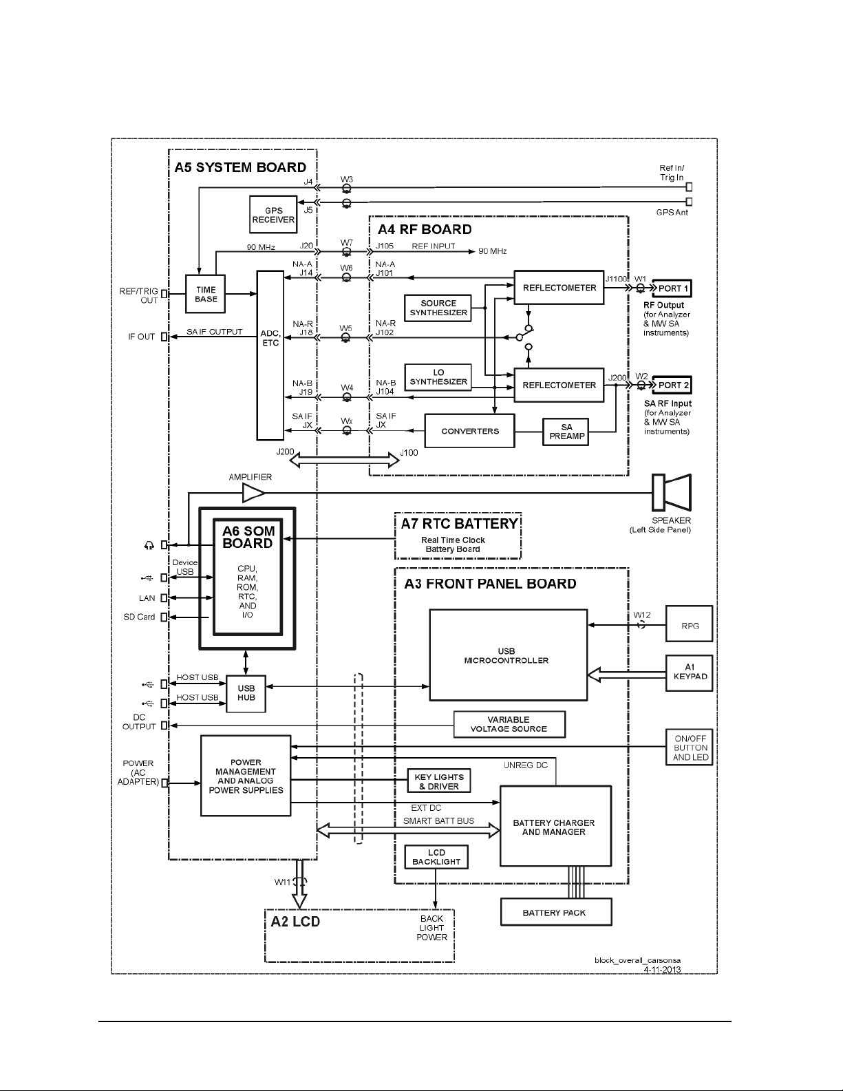
See Figure 5-1 for a simplified block diagram of the overall RF analyzer system.
All FieldFox analyzers covered by this manual have the same hardware. Options to increase
functionality are enabled via licenses, additional hardware is not required.
Functional Groups of the Analyzer
The operation of the analyzer can be separated into two major functional groups. Each group consists of
assemblies that perform distinct functions. Some of the assemblies are related to more than one group,
and both groups, to some extent, are interrelated and affect each other's performance.
The major functional groups are:
• Front Panel Group
• Measurement Group
Front Panel Group
The front panel group consists of the following:
• A2 LCD Assembly
• A3 Front Panel Interface Board
Measurement Group
The measurement group consists of the following:
• A4 RF Board
• A5 System Board
• A6 SOM Board
• A7 Real Time Clock Board
• Main Battery
N9927-90003 5-3
Page 54
Theory of Operation FieldFox Analyzer
Analyzer System Operation
Figure 5-1 Overall Block Diagram
5-4 N9927-90003
Page 55

FieldFox Analyzer Theory of Operation
Front Panel Group
Front Panel Group
The front panel group consists of the following assemblies:
• A3 Front Panel Interface Board
• A2 LCD Assembly
Refer to Figure 5-1 for a simplified overall block diagram which includes the front panel group.
A3 Front Panel Interface Board
The main function of the A3 Front Panel Interface board is to support the user interface but it also
contains the digital power supplies.
USB Microcontroller
The USB Microcontroller senses the keypad keys and the RPG (rotary pulse generator) knob on the front
panel. The USB Microcontroller communicates with the A5 System board via a USB interface.
There is no separate ID EPROM on the A3 Front Panel Interface board. All ID information is stored in
the USB Microcontoller .
Keypad Lights and ON/OFF Button
The power for the keypad LED's generated on the A3 Front Panel Interface board is derived from the
+5 V digital supply. The keypad LED's are turned on for a few seconds following each key press. This
function is controlled by the firmware on the A6 SOM board.
The On/Off LED is controlled by a signal from the A5 System board. The connections for the On/Off
Button and LED are direct to the A5 System board.
LCD Backlight
Power for the backlight on the A2 LCD assembly is generated on the A3 Front Panel Interface board.
Digital 5 volts is converted to approximately 25 volts. The actual voltage determines the brightness of
the backlight. Two control lines from the A5 System board control on/off and intensity functions. These
control lines are driven by the system monitor microcontroller on the A5 System board.
Battery Charger and Manager
This circuitry controls charging of the battery based on a battery charger IC. This IC is powered by a
digital output on the System Monitor. The System Monitor has the capability to reset the IC, if required,
by recycling the power to the IC.
This circuitry also controls the source of the Unreg DC: Batt or Ext DC. It reads the battery pack
information via the Smart Batt Bus. Batt Neg is connected to the A5 ground plane.
There is an input inrush current control circuit on the Ext DC input that limits inrush current to 4 amps.
Variable Voltage Source
This circuitry provides a constant voltage intended to bias circuits under test.
The user interface for controlling this function may be accessed via
N9927-90003 5-5
System > System Configuration
.
Page 56

Theory of Operation FieldFox Analyzer
Front Panel Group
A2 LCD Assembly
The A2 LCD assembly contains a 6.5-inch, 640 x 480 TFT color LCD with associated drive circuitry and
backlight inverter.
The LCD backlight is created by LED’s connected in parallel stacks. Backlight brightness is a function
of the backlight power that ranges from 22 to 27 volts. Refer to “LCD Backlight” on page 5-5 for more
information.
The backlight LED’s are arranged along the top and bottom edges of the display. There are three stacks
on each edge.
5-6 N9927-90003
Page 57

FieldFox Analyzer Theory of Operation
Measurement Group
Measurement Group
The measurement group produces a stable output signal by phase locking a synthesized
voltage-controlled oscillator (VCO).
The measurement group consists of the:
• A4 RF Board
• A5 System Board
• A6 SOM Board
• A7 Real Time Clock Board
• Main Battery
A simplified RF block diagram is provided in Figure 5-2..
A simplified system block diagram is provided in Figure 5-3.
A4 RF Board
A basic function of the A4 RF board is to provide a signal source and receivers for the analyzer
functions.
There are two sections to the A4 RF board:
• NA RF section
• SA RF section
N9927-90003 5-7
Page 58

Theory of Operation FieldFox Analyzer
Measurement Group
Figure 5-2. Simplified RF Block Diagram
5-8 N9927-90003
Page 59

FieldFox Analyzer Theory of Operation
Measurement Group
NA RF Section
An LO synthesizer produces a single LO signal from the 90 MHz time base located on the A5 System
board. The LO output is delivered to the NA mixers of both ports. The LO frequency is always above the
measured frequency. The IF is 390 kHz.
The LO output is switched between the NA mixers and the SA first converter depending on the function
being used. At any instant in time, either the NA receivers or the SA receiver may be active, but not both
at the same time.
The 90 MHz time base is also used to generate a source signal in the source synthesizer that covers the
frequency range of 10 MHz to 26.5 GHz. The source signal is generally rich in harmonic content. This is
acceptable because the signal is used with tuned receivers.
The frequency bands for the NA circuitry on the RF board are listed below:
Band Instrument
Start Stop
P1 0.030 2.035
2 2.035 2.425
3 2.425 4.500
4 4.500 4.850
5 4.850 9.350
6 9.350 9.700
7 9.700 19.100
8 19.100 19.500
9 19.500 38.800
10 38.800 78.000
11 78.000 156.250
12 156.250 312.500
13 312.500 625.000
14 625.000 1250.000
15 1250.000 2500.000
16 2500.000 5000.000
17 5000.000 10000.000
18 10000.000 15000.000
19 15000.000 20000.000
20 20000.000 26500.000
N9927-90003 5-9
Page 60

Theory of Operation FieldFox Analyzer
Measurement Group
The RF Out attenuator between the source and the reflectometer has three settings: nominal values of
0 dB, 35 dB or user input value. The setting is determined by the High, Low or Manual power setting on
the user interface. And beginning from firmware A.06.18, the default output power level is -15 dBm.
The reflectometer performs three functions:
• It passes the source output signal to either PORT 1 or PORT 2.
• It samples the source output to either PORT 1 or PORT 2.
• It samples the incoming signal at either PORT 1 or PORT 2.
The sampled signals are mixed with the LO signal to produce three 390 kHz IF signals, NA-A, NA-B
and NA-R.
The reflectometer dissipates up to 1.5 watts when active.
Each port (PORT 1 and PORT 2) has a DC isolation capacitor.
5-10 N9927-90003
Page 61

FieldFox Analyzer Theory of Operation
Measurement Group
SA RF Section
An external RF input signal can be analyzed when connected to the Port 2 SA RF Input connector.
Before the input signal is mixed, the signal will go through the input attenuator and optional internal
preamplifier.
The input attenuator default setting from the factory is 10 dB. The input attenuator is used to control the
amount of power at the input of the 1st converter. Changing the input attenuator value can improve the
dynamic range of the instrument and reduce internally generated distortion products.
When the optional internal preamplifier is turned on, the displayed average noise level of the instrument
is improved. This occurs because the noise figure of the overall system is improved. Improving the
displayed average noise level of the system enables the user to analyze low level input signals.
The 1st, 2nd and 3rd converters are used to downconvert the input signal to a final I.F. of 33.75 MHz.
That I.F. is fed to the ADC on the A5, System board. This final I.F. on the output of the ADC can be
measured at the IF Out SMB (m) connector on the side of the instrument. Refer to “Verifying the 33.75
MHz I.F. Output” on page 4-11.
The frequency bands for the SA circuitry on the RF board are listed below:
Band Instrument
Start Stop
1 0.030 15.000
2 15.000 500.000
3 500.000 1366.250
4 1366.250 2600.000
5 2600.000 3900.000
6 3900.000 7500.000
7 7500.000 9500.000
8 9500.000 12300.000
9 12300.000 15700.000
10 15700.000 16300.000
11 16300.000 19500.000
12 19500.000 23000.000
13 23000.000 23734.000
14 23734.000 25500.000
15 25500.000 26500.000
N9927-90003 5-11
Page 62

Theory of Operation FieldFox Analyzer
Measurement Group
Power Management Circuitry
The circuitry on the A4 RF board has five special sections that may be powered down for the purpose of
power management. These sections may be selectively powered down (via “load switching”) when not
required for the current operating mode of the analyzer.
The sections that may be selectively powered down are:
• Source—most of the source synthesizer circuitry
• LO—most of the LO synthesizer circuitry
• SA—most of the first, second, and third converter circuitry
• Reflectometer—put into a low power state
• High-Band Pre-amp—high band section of the pre-amp turned off
The load switching for the Source and LO sections is accomplished on the A5 System board via the
Analog Linear Regulators and Load Switching circuitry.
The load switching for the Reflectometer and High-Band Preamp is accomplished on the A4 RF board.
Other Circuitry
The FPGA (Field Programmable Gate Array) communicates with the FPGA on the A5 Syst em board via
FPGA Serial Bus. It provides the digital control for the functions on the A4 RF board. It also reads the
VCO unlock signals.
RF Serial Bus allows the System Monitor on the A5 System board to read a temperature sensor and the
ID EPROM for the A4 RF board.
5-12 N9927-90003
Page 63

FieldFox Analyzer Theory of Operation
Measurement Group
A5 System Board
The A5 System board controls all of the functions of the analyzer and digitizes the RF IF signals (NA-R,
NA-A, NA-B, and SA IF) from the A4 RF board.
The A6 SOM (System on Module) board is mounted directly on the A5 System board.
All external connections for the analyzer come through the A5 system board except for the PORT 2 and
PORT 1 ports.
The A5 System board also controls the power switching and power management.
The instrument model number and serial number are stored on the A5 System board.
N9927-90003 5-13
Page 64
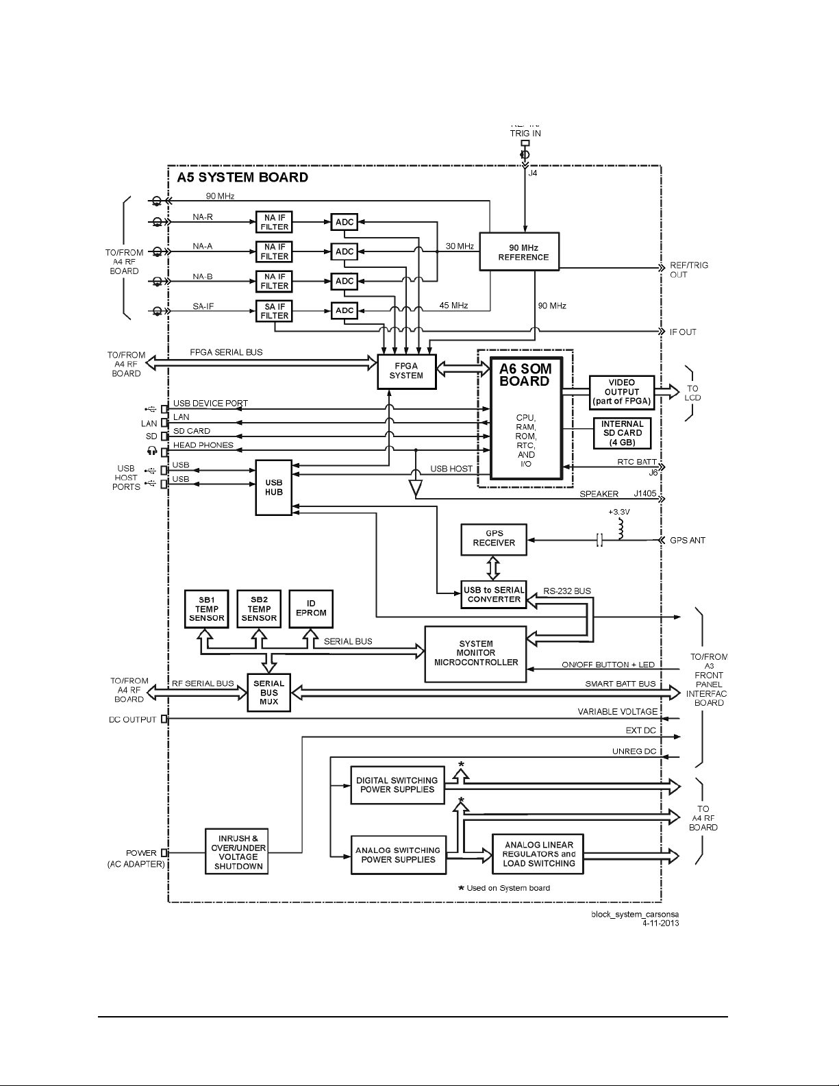
Theory of Operation FieldFox Analyzer
Measurement Group
Figure 5-3 Simplified System Board Block Diagram
5-14 N9927-90003
Page 65

FieldFox Analyzer Theory of Operation
Measurement Group
System Monitor (SM) Microcontroller
This is the heart of the analyzer. It is active whenever there is DC power available. The microcontroller
has ultra-low power dissipation. It is sometimes referred to as the “MSP 430”.
The following is a list of some of the functions performed by the SM.
• It monitors the On/Off button on the front panel and responds appropriately.
• It controls the on/off functions of the various power supplies in the analyzer.
• It drives the On/Off button LED.
• It reads battery pack information via the Smart Batt Bus.
• It communicates with the battery charger IC via the Smart Batt Bus.
• It interfaces to the Battery Charger and Manager circuit.
• It interfaces to the Serial Bus for communication with the temperature sensors and ID EPROM’s on
the printed circuit boards.
• It communicates to the A6 SOM board CPU via a serial port, UART.
• It stores the instrument model number and serial number.
USB Hub
This circuitry expands the number of USB ports available to the FieldFox firmware.
Power Management and Power Supplies
Seven different analog supply voltages are generated from the Unreg DC. All of these are used on the A4
RF board and some are used on the A5 System board.
Some sections of the circuitry on the A4 RF board may be switched to low power modes to conserve
power and minimize heat. This is accomplished through load switching. See “Power Management
Circuitry” on page 5-12 for more information.
The System Monitor controls the on/off functions of the analog power supplies. All are on or of f together
except for power sequencing.
This circuitry also monitors the Ext DC input and, if below 10.8 volts or above 21 volts, it disconnects
this input from the Unreg DC.
FPGA
This FPGA:
• provides the interface between the A6 SOM board and the ADC,
• provides miscellaneous interfaces for circuitry on the A4 RF board, and
• communicates with the CPU via the USB interface.
N9927-90003 5-15
Page 66

Theory of Operation FieldFox Analyzer
Measurement Group
Time Base
The Time Base is an internal TCXO that produces 90 MHz signals for use throughout the analyzer.
A 10 MHz signal at the Ref In/Trig input may be used to provide an external time base. The external time
base function is controlled via the user interface. Refer to the “Frequency Reference Source” section of
the FieldFox Analyzer User’s Guide (Part Number N9927-90001) for additional information.
The internal 10 MHz frequency reference is available from the Ref/Trig Out connector on the right-side
panel. Use this signal as a common frequency reference when making measurements using external
equipment
Filters, MUX, and ADC’s
The three Filters filter the IF signals in preparation for the ADC. Filter characteristics are fixed (not
programmable).
The ADC’s digitize each of the IF signals received fro m the A4 RF board. The input to one of the ADC’s
is multiplexed between the NA-A and NA-B input signals.
The 14-bit ADCs sample at a rate of 30 mega samples per second.
Each ADC may be put into a low power mode when not active.
Temperature Sensors
The SB1 Temp Sensor is located on the A4 RF board side of the A5 System board near the headphone
jack (J3).
The SB2 Temp Sensor is on the A4 RF board side of the A5 System board near the edge of the board
against the battery compartment. This temperature sensor is not under a shield.
Audio Output
The speaker is located on the left side panel of the case. Left and right audio signals from the A6 SOM
board go to the headphone jack on the A5 System board. These signals are then combined to create a
single mono signal for the speaker. An amplifier drives the speaker. Plugging in the headphones disables
the speaker output.
LAN Connector
The LAN connector supports the LAN interface on the A6 SOM board. See “LAN Interface” on page
5-30 for more details.
SOM Connector
Refer to “A6 SOM Board” on page 5-17 for information on SOM (System on Module) functions.
5-16 N9927-90003
Page 67

FieldFox Analyzer Theory of Operation
Measurement Group
A6 SOM Board
The A6 SOM (System on Module) board plugs directly into the A5 System board as a daughter board
and contains:
•the CPU,
• 64 MB of flash ROM,
• 128 MB of RAM
• real time clock, and
• I/O interface.
The interfaces on the SOM are:
• UART to the System Monitor on the A5 System board
• LCD interface
• Left and right audio outputs
• SD card bus
• USB host interface
• Interface to USB hub
• LAN interface 10/100 base T
• General purpose interface lines
The A6 SOM board is powered by the 3.3 volt digital supply.
Licenses which enable instrument options are stored in the A6 SOM flash ROM.
A7 Real Time Clock Board
The battery for the RTC (real time clock) on the A7 RTC is connected to the A6 SOM board via the A5
System board. The battery powers the RTC when the FieldFox is powered off.
Chapter 7 provides instructions for replacing the battery on the A7 RTC board.
Main Battery
The battery is a rechargeable 10.8 V lithium-ion type. Refer to “Battery Disposal” on page 1-7 for
important information about replacing and disposing of this battery.
Refer to “Battery Related Information” on page 5-20 for details on the main battery.
N9927-90003 5-17
Page 68

Theory of Operation FieldFox Analyzer
Grounding and Power
Grounding and Power
Grounding
Each printed circuit board has a single ground plane. The ground planes on the A4 RF board and A5
System board are connected via the common shields at multiple points. The ground plane on the A3
Front Panel Interface board is connected to the ground plane on the A5 System board.
There are no separate grounds in the analyzer. There is no “star” ground point in the analyzer.
Batt Neg and Ext DC neg are connected to the A5 System board ground plane.
The A2 LCD assembly has two separate grounding circuits: the LCD power and control circuits and the
backlight LED’s.
• The LCD power and control circuits share a ground that is connected to the ground plane on the A5
System board.
• The ground for the backlight LED’s is connected to the ground plane on the A3 Front Panel Interface
board.
Voltages and Power Supplies
The following power supplies exist within the analyzer:
• Digital 5 volts—generated from Unreg DC on the A3 Front Panel Interface board, controlled by the
System Monitor on the A5 System board, and used on the A3, A4, and A5 boards.
• Digital 3.3 volts—generated from Unreg DC on the A3 Front Panel Interface board, on/off functions
controlled by the System Monitor on the A5 System board, and used on the A2 LCD assembly and
A3, A4, A5, and A6 boards.
• Analog supply voltages—seven separate voltages generated from Unreg DC on the A5 System board,
on/off functions controlled by the System Monitor on the A5 System board.
• LCD backlight voltage—generated on the A3 Front Panel Interface board from the digital 5 volt
supply voltage.
• Power for the System Monitor circuit—3.3 volt circuit powered from Ext DC or Batt +, whichever is
greater. Used on A5 System board only.
• Unreg DC—from Ext DC or Batt +, 21 volts max.
• Ext DC—from external Power AC Adapter, nominal 15 volts, acceptable up to 19 volts.
• Batt + —from main battery, nominal 12 volts.
All voltages except Ext DC, Batt +, and the System Monitor power can be turned on/off within the
analyzer. Refer to “Power Management Circuitry” on page 5-12 for more information.
5-18 N9927-90003
Page 69

FieldFox Analyzer Theory of Operation
Grounding and Power
Power Control and Management
Power States
The On/Off Button is used to switch between On, Off, and Standby power states:
Off Only the System Monitor and battery control circuits are powered up (if power is available from
the battery or external power).
If the battery is charging, the LED below the On/Off Button slowly flashes orange with increasing
intensity, otherwise this LED is off.
Some battery power is required in the “Off” state. A fully charged battery will discharge completely
in four to six weeks when left in the analyzer.
On This is normal operation. The On/Off Button LED is steadily lit green.
Standby Only the digital power supplies are on. The CPU is in a low power state, maintaining RAM
content. The On/Off Button LED flashes yellow briefly every two seconds.
During normal operation, unexpectedly disconnecting power to the analyzer (such as removing the main
battery when the analyzer is not connected to external power) should not cause any problems. Simply
re-apply power. No firmware problems are expected. Of course, this does not apply during a firmware
upgrade.
Smart Power Management
The analyzer uses extensive “load switching” to minimize power dissipation. This is termed Smart
Power Management (SPM). There are two motivations for power management:
• to extend battery run time
• to prevent overheating.
Sections of the circuitry are selectively powered down via “load switching”, depending on th e op erating
mode of the analyzer. Five different sections of the circuitry on the A4 RF board may be controlled via
“load switching”. These sections are as follows:
• Source—switched off during SA mode, switched off between sweeps during CAT or NA modes.
• LO—switched off when data is not being taken by receivers.
• SA—switched off when in one port CAT or NA modes, on all the time in two port mode.
• Reflectometer—switched to low power through state when RF OUT port receivers are inactive.
• High-Band Pre-amp—switched off when not required.
On the A5 System board, each of the ADC’s may be individually switched to a low power mode when
not active.
Load switching is generally transparent to the user. One obvious exception is the that the source turns off
during “retrace” in the CAT and NA modes.
N9927-90003 5-19
Page 70

Theory of Operation FieldFox Analyzer
Grounding and Power
Battery Related Information
Battery Description and Operation
The main battery is an SBS (Smart Battery System) compliant pack of lithium ion cells.
Refer to “Battery Disposal” on page 1-7 for important information about replacing and disposing of this
battery.
The nominal voltage of the battery is 10.8 volts and normally varies from 9 to 12 volts.
The battery has built-in sensors, a processor, and control circuitry . This is referred to as the Smart Battery
circuitry.
The Smart Battery circuitry communicates battery condition and history information digitally via a
digital Smart Batt Bus. The Smart Battery circuitry is read-only.
Both the battery charging circuit and the System Monitor read battery information over the Smart Batt
Bus.
The battery temperature reported by the analyzer is based on a sensor inside the battery. Temperature
information is available over the Smart Batt Bus. The thermistor connection (T) on the battery is not
used.
The Smart Battery circuit may shut down the battery when the temperature is out of the acceptable range
or when the battery charge is too low.
See the “Working with the Lithium-Ion Battery” section of the FieldFox User’s Guide for additional
information on:
• built in charge level gauge
• the battery information screen
• battery care
Battery Information Screen
Refer to the FieldFox User’s Guide for information on how to access this screen.
Most of the items displayed on the screen come directly from the battery via the Smart Batt Bus. Only
the first three items are influenced by the analyzer.
5-20 N9927-90003
Page 71

FieldFox Analyzer Theory of Operation
Grounding and Power
Battery Charging Management
The battery pack determines when the battery needs charging and requests a charge over the Smart Batt
Bus.
The Battery Charger and Manager circuit on the A5 System board responds by charging the battery if
there is sufficient voltage on the Ext DC line. A minimum of approximately 15 volts is required to charge
the battery .
The System Monitor on the A5 System board monitors the battery’s temperature and, if too high or too
low, disables charging of the battery.
How to tell if the battery is charging:
• If the analyzer is On, the lightening bolt is displayed in the battery icon.
• If the analyzer is Off, the LED below the On/Off Button slowly flashes orange with increasing
intensity.
• If the analyzer is in Standby, turn the analyzer on and observe the battery icon.
The battery charges much faster up to 70% of its full charge than it does above 70% of full charge.
Battery Life
When a battery is new , an instrument should operate for about fo ur hours on a fu lly ch arged battery. The
actual time will depend on operating mode and temperature.
As a battery goes through charge/discharge cycles, its capacity will decrease. A typical battery will have
more than 70% of its initial capacity after 200 full discharge cycles when operating at 20 to 30 °C
ambient temperature.
N9927-90003 5-21
Page 72
Theory of Operation FieldFox Analyzer
Operation in Modes
Operation in Modes
The FieldFox User’s Guide describes the various modes of operation and describes the user interface for
each mode. The following information describes how the hardware is used in the various modes to make
measurements.
There are six basic modes of operation:
• CAT—Cable and Antenna Test
• NA—Network Analyzer
• SA—Spectrum Analyzer
• VVM—Vector Voltmeter
• PM—Power Meter (USB Sensor)
• CPM—Channel Power Meter
CAT, NA, and VVM modes have similar capabilities but are separate modes of operation.
The six basic modes listed above represent how the hardware may be used to make basic measurements.
Additional modes will provide customized user interfaces but will not change how the basic
measurements are performed.
The following table indicates various modes in FieldFox analyzers and the option dependencies. See the
“Service Related User Operations” section of Chapter 8 for more details.
Modes CAT NA SA VVM
Standard Option 210 Option 210 Option 210 Option 210 Option 210
CAT Measure
NA
Measure
Distance To
Fault (dB)
Cable Loss
(1-Port)
Standard Option 210 Standard
S11 S21 S12 S22
Return Loss &
DTF
Insertion Loss
(2-Port)
Option 210 Option 211 Standard
Return Loss
(dB)
Standard
DTF
(Lin)
Power Meter
(USB Sensor)
VSWR DTF (VSWR) More
Format
(Log Mag)
Power Meter
(Built In)
NA
Meas Setup
5-22 N9927-90003
Settings
Standard Standard Standard Standard Standard Option 010
Calibration
Settings
Power Level
Output Power
High Low Man
Port
Extensions
Transform
Page 73

FieldFox Analyzer Theory of Operation
Operation in Modes
CAT or
NA Cal
VVM
Measure
SA Measure
SA Source
Response
Cal
Standard Option 112 Standard Standard Standard
1-Port Cable
Trimming
Option 308
Radio
Standard
Option 233 Option 233 Option 233 Option 236
Source
Enable
OFF ON
Source Mode
Tracking
Option 233
& 210
QuickCal
2-Port
Transmission
Option 308 &
210
Channel
Measurements
Source Mode
(CW)
Source Mode CWSource Mode
Option 233 Option 233 Standard Standard
Mechanical
Cal
B/A A/B
Option 308
& 210 & 211
Tune &
Listen
Normalize
OFF ON
Coupled CW
Cal OFF ON View Cal
Option 308 &
210 & 211
Interference
Analysis
Source Power
Source
Option 233 &
Source CW
Freq
210
SA
Scale/Amptd
SA Trace
Autoscale Unit dBm Corrections External Gain
Standard Standard Standard Standard Option 235
Trace
1 2 3 4
Standard Standard Standard Standard Option 236 Option 236
State (Clr/Wr) Default All Detector (Auto)
Preamp
OFF ON
Record
Playback Setup
Recorder
Player
For a given mode, the analyzer “remembers” the most recent state of the current mode when you change
to another mode.
For most screens under System 7 key, the current measurement mode continues to operate while the
screen is displayed. For instance, while the battery information screen is displayed, the measurement
mode remains active.
There are two exceptions to this:
• the “Options (Licensing)” screen
• “Error Log” screen
When either of these screens is displayed, the firmware is in a special monitor mode and measurements
are suspended.
N9927-90003 5-23
Page 74

Theory of Operation FieldFox Analyzer
Operation in Modes
CAT, NA, and VVM Modes
CAT, NA, and VVM modes have some similar capabilities but are still separate operating modes.
Measurement similarities:
• Return Loss = S11 magnitude
• Insertion Loss = S21 magnitude
Unlike S11 and S21, the values displayed below zero for Return Loss and Insertion Loss are not
negative.
There is user control of output power level, which is high, low or manual setting on the RF Out Atten, 35 dB
in or out.
SA and CPM Mode
SA Mode measures signals at the SA RF IN connector.
SA Mode measurements require NO calibration.
The signal path for SA mode is the same as the input path for two port CAT/NA modes.
The RF In Atten can be set from 0 through 30 dB in 5 dB steps. The Attenuator Slope Adjustment
determines the correction factors for each step in each frequency band.
The RF In Atten can be controlled manually or automatically. When in auto mo de , the Re fe re nc e Lev e l
setting determines the attenuator setting.
The Pre-amp can be in or out. Nominal gain of the pre-amp is 22 dB.
The “Attn” and “PA” indicators in the display header give current status. The Scale/Amptd hard key
provides access to control for them.
The displayed measured value for a given signal is automatically compensated for in the current Attn and
PA settings. For instance, if an incoming signal is measured at -70 dBm with the RF IN Atten set to 5 dB
and PA “out”, changing to PA “in” will give a measured value of approximately -70 (+/- because the 22
dB for the PA is only nominal). The difference seen in the trace will be that the noise floor of the trace
will be lowered by approximately 22 dB. If the RF In Atten is changed from 5 dB to 15 dB, the measured
value will not change significantly (still approximately -70 dBm) but the noise floor will raise by 10 dB.
SA has two basic modes: step and FFT.
Step mode reads a narrow slice of the spectrum and the LO steps for each slice. In this mode, a trace on
the display is composed from multiple slices. Generally spans greater than 100 kHz operate in step
mode.
FFT mode reads a wide slice of the spectrum and the LO is fixed. In this mode, a trace on the display is
based on a single LO setting.
The LO minimum step size is 2 MHz; this restriction limits spurs.
The hardware operation of the A/D’ s is essentially the same for both step and FFT modes. The difference
is the digital signal processing.
The SA adjustments generally correct the gain with 11 frequency bands. See page 5-11 for a listing of
the 11 bands. See the TME help file for details on SA adjustments.
5-24 N9927-90003
Page 75

FieldFox Analyzer Theory of Operation
Temperature Related Information
Power Meter Mode
All measurement circuitry is switched to the low power state during PM (power meter) mode. This is the
mode with the lowest power dissipation.
The analyzer has no power output capability in this mode. The analyzer essentially functions as a display
for a USB power sensor.
Temperature Related Information
Five temperature sensors are in the analyzer: two on the A4 RF board, two on the A5 System board, an d
one in the battery pack.
• RF1—on the A4 RF board
• RF2—on the A4 RF board
• SB1—on the A5 System board
• SB2—on the A5 System board
• Battery pack—inside the battery pack
The battery pack has its own internal temperature sensor. The battery pack will shut itself down in the
case of extreme temperatures.
See Chapter 8 for instructions on viewing temperature readings.
See the FieldFox Analyzer User’s Guide (Part Number N9927-90001), “FieldFox High-Temperature
Protection” section, for information about operation at high temperature.
During normal operation, as each SA measurement is taken, the current RF2 temperature reading is
compared tot he temperature stored for the Frequency Response adjustment. A delta temperature is
calculated. Each SA measurement is adjusted to compensate for the delta temperature.
The internal temperature of the unit is critical when executing the TME based software for tests and
adjustments. See the TME help for detailed information.
Under typical bench top (indoor) conditions, the internal temperature of the unit will be about 20 °C
above ambient once the internal temperature has stabilized. It will typically take 60 to 90 minutes for the
internal temperature to stabilize when a “cold” unit is turned on.
N9927-90003 5-25
Page 76

Theory of Operation FieldFox Analyzer
User Calibration in CAT, NA, and VVM Modes
User Calibration in CAT, NA, and VVM Modes
There are three types of calibrations for the CAT, NA and VVM modes: CalReady, QuickCal and
Mechanical Cal. See the FieldFox Analyzer User's Guide (Part Number N9927-90001) "Calibration for
CAT, NA and VVM Modes" section for specific instructions for performing these calibrations. Because
NA, CAT, and VVM modes are very similar, a calibration that is performed in one mode can also be
applied in the other modes.
When a user calibration is performed, the full frequency range of the analyzer is calibrated even though
the current state of the analyzer may be less than the full range. This allows a calibration to be
"interpolated" beyond the frequencies set at the time of calibration (an asterisk "*" on the display
indicates interpolation).
Do not leave cal standards connected to the PORT 2 or PORT 1 ports for more than three minutes. Heat
in the port connectors may affect the accuracy of the standards.
Factory Calibration (CalReady)
When the analyzer is adjusted at the factory or during annual calibration, a preset calibration is stored in
the analyzer (CalReady).
The preset calibration covers the full frequency range of the analyzer. The preset calibration is active
whenever “CalRdy” is displayed on the left side of the screen. Presetting the analyzer activates the preset
calibration.
The preset calibration provides very good measurement performance at the PORT 1 and Port 2
connectors when the analyzer has thermally stabilized at room temperature.
The preset calibration should be re-characterized every 12 months to maintain accuracy. This is
accomplished via the Error Terms adjustment in the TME. Refer to Chapter 3.
QuickCal
The QuickCal function mathematically “extends” the preset calibration to the end of a cable or adapter. It
is a firmware only function; it does not involve analyzer hardware.
Table 5-1. Cal Status Indicators
Indicator Meaning Additional Indicators
CalRdy Preset (factory) calibration is active
Cal ON Q Quick Cal calibration is active
Cal ON U User calib ration is active
* = interpolation active
? = Measurement conditions have changed.
* = interpolation active
? = Measurement conditions have changed.
* = interpolation active
? = Measurement conditions have changed.
Cal OFF Calibration is inactive
Cal OFF*
5-26 N9927-90003
No calibration available to activate for
this measurement.
Page 77

FieldFox Analyzer Theory of Operation
User Calibration in CAT, NA, and VVM Modes
Mechanical Calibration
Mechanical Calibration is performed using discrete standards from a Cal Kit. Several Cal Kit definitions
are built into the FieldFox.
Mechanical Cals are extremely accurate when performed using the correct Cal Kits with standards that
are clean and in good repair, and when using correct connection procedures.
N9927-90003 5-27
Page 78

Theory of Operation FieldFox Analyzer
Firmware Related Information
Firmware Related Information
General Description
The analyzer is based on the Windows CE1 operating system. This is a closed system; no direct user
access to the desktop of general operating system functions is provided.
The file system for Windows CE is maintained in flash memory on the A6 SOM board. There is limited
access to the file system. Most memory is in a protected region and not directly accessible by the user.
The user accessible memory is under UserData. See the “File Management” section of the FieldFox
Analyzer User’s Guide (Part Number N9927-90001) for instructions on saving, recalling, and managing
files in the unprotected memory.
User Accessible Files
• Directory structure below UserData in the A6 SOM board flash memory.
• External USB flash memory plugged in the analyzer.
• External SD memory card plugged into the analyzer.
NOTE: When copying files, a “Copy_....” directory is created at the root of the destination device as the
destination for the copied file(s). This characteristic generally makes it impossible to copy a file into the
desired directory under UserData in the A6 SOM board flash memory. This limits the usefulness of
copying files to or within UserData.
Operational Files
• Results from adjustments performed under TME (see Chapter 3)—not directly available to user .
• File resulting from CAT/NA/VVM user calibration—not directly available to user.
• Cal kit definition files—stored in UserData\calkits.
• Cable definition files—stored in UserData\Cables.
• Error log—not directly available to user . See “Err or Log” further on in this section for accessing error
log information.
Erase User Data Utility
A utility to erase all directories and files in the UserData directory is available. After the flash memory is
erased, the boot process returns the UserData directories and files to the state as shipped from the factory .
The System Information screen indicates the time and date of the most recent erase.
See Chapter 8 for instructions on executing the Erase User data utility.
1. Windows® and Windows CE® are U.S. registered trademarks of Microsoft Corporation.
5-28 N9927-90003
Page 79

FieldFox Analyzer Theory of Operation
Firmware Related Information
Error Log
See Chapter 8 for instructions on viewing the error log.
The error log is cleared each time the analyzer is powered off.
Generally, an entry in the error log is created whenever an error message is displayed.
EXAMPLE: Attempting to set the frequency to a value of “.” (a decimal point), will generate an entry in
the error log.
Firmware Upgrades
Firmware upgrades are available on the Internet. Refer to instructions in the “Update FieldFox
Firmware” section of the FieldFox Analyzer User’s Guide (Part Number N9927-90001) for details.
See Chapter 8 for instructions on viewing the current firmware revision.
The following information will be included in the display.
• Firmware Release = FieldFox application firmware revision
• FPGA Rev = code revision for FPGA
• SBM Boot Rev = revision of boot code for System Microcontroller
• SBM Main Rev = revision of main code for System Microcontoller
A firmware upgrade includes three sections:
• the FieldFox application firmware and the Windows CE operation system on the A6 SOM board.
• the firmware in the System Monitor Microcontroller on the A5 System board.
• the FPGA code on the A5 System board.
The System Monitor firmware update and the FPGA code update are executed only if not up-to-date.
It is important to maintain power to the analyzer during the update process.
After unplugging the USB flash memory stick during the firmware upgrade process, wait for the
analyzer to enter its default operating mode before operating the analyzer.
N9927-90003 5-29
Page 80

Theory of Operation FieldFox Analyzer
LAN Interface
LAN Interface
See the “System Configuration” section of the FieldFox Analyzer User’s Guide (Part Number
N9927-90001) for details on reviewing and configuring LAN settings.
The LAN interface supports Auto MDIX. When a LAN cable is connected to the FieldFox, if the other
end of the cable supports Auto MDIX, there is no need for a cross-over cable.
There are two LEDs on the LAN connector. When there is successful communication over a LAN cable,
both LEDs are active. If both LEDs are not active, consider using a cross-over cable.
5-30 N9927-90003
Page 81

6 Replaceable Parts
N9927-90003 6-1
Page 82
Replaceable Parts FieldFox Analyzer
Information in This Chapter
Information in This Chapter
This chapter:
• identifies the replaceable parts for the FieldFox analyzer.
• includes several tables and illustrations to assist you in identifying the correct part for your analyzer.
• contains ordering information for new assemblies and rebuilt-exchange assemblies.
Section Title Summary of Content Start Page
Ordering Information
Assembly Replacement Procedure
Replaceable Parts Listings
How to order a replaceable part from Agilent
Technologies.
The correct sequence for determining the failure of and
replacing a defective assembly.
T ables with illustra tions that list all replaceable parts in
your analyzer:
Page 6-3
Page 6-4
Page 6-5
6-2 N9927-90003
Page 83

FieldFox Analyzer Replaceable Parts
Ordering Information
Ordering Information
To order a part listed in the replaceable parts lists:
• include the part number
• indicate the quantity required
• Contact Agilent Technologies for instructions on where to send the order. Refer to
“Contacting Agilent” on page 2-9.
To order a part that is not listed in the replaceable parts lists:
• include the instrument model number and complete instrument serial number
• include the description and function of the part
• indicate the quantity required
• Contact Agilent Technologies for instructions on where to send the order. Refer to
“Contacting Agilent” on page 2-9.
N9927-90003 6-3
Page 84

Replaceable Parts FieldFox Analyzer
Assembly Replacement Procedure
Assembly Replacement Procedure
The following steps describe how to replace an assembly in the analyzer.
Step 1. Identify the faulty group. Begin with Chapter 4 , “Troubleshooting.” Follow up with the
appropriate troubleshooting chapter that identifies the faulty assembly.
Step 2. Order a replacement assembly. Refer to this chapter for part numbers and ordering
information.
Step 3. Replace the faulty assembly and determine what adjustments and performance tests are
necessary. Refer to Chapter 7 , “Repair and Replacement Procedures.”
Step 4. Perform the necessary adjustments. Refer to Chapter 3 , “Tests and Adjustments.”
Step 5. Perform the necessary performance tests. Refer to Chapter 3 , “Tests and Adjustments.”
6-4 N9927-90003
Page 85
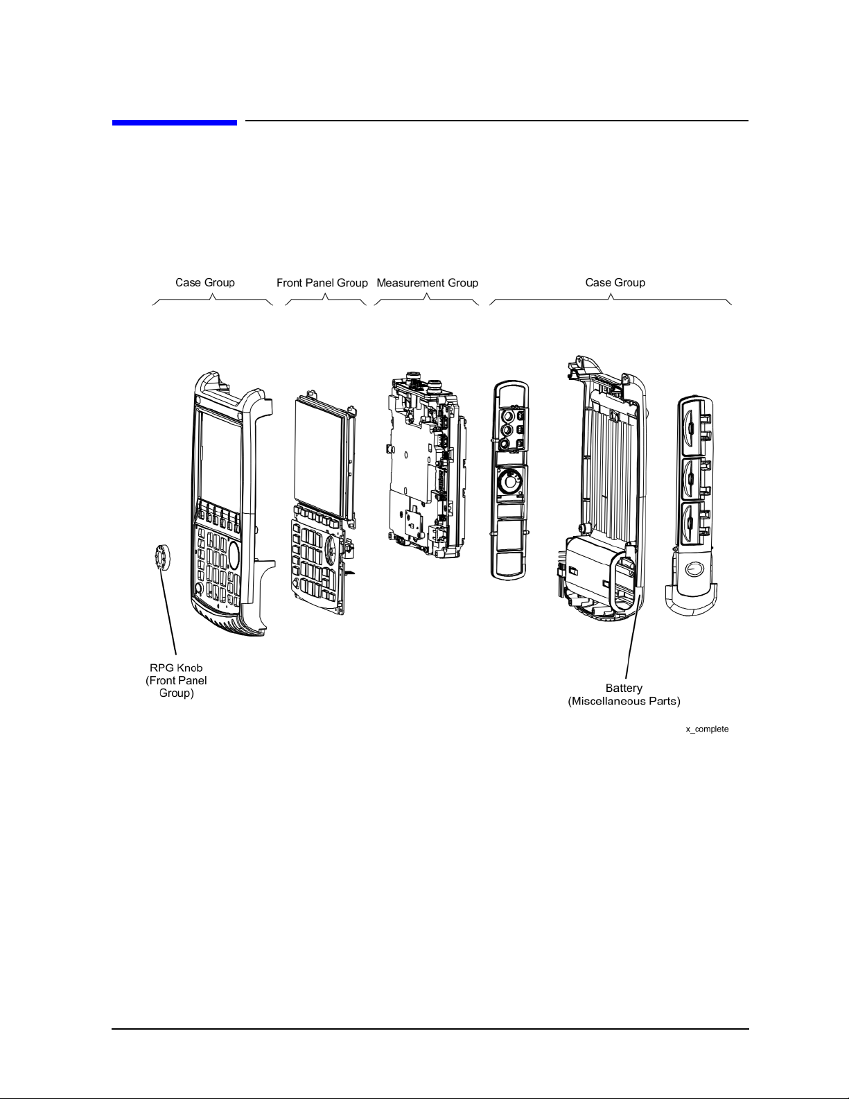
FieldFox Analyzer Replaceable Parts
Replaceable Parts Listings
Replaceable Parts Listings
Entire Analyzer
Figure 6-1 Entire Analyzer, Exploded View
Descriptions and part numbers for the assemblies and parts in each group shown in the above illustration
can be found at the following locations:
• “Front Panel Group” on page 6-6
• “Measurement Group” on page 6-8
•
“Case Group” on page 6-11
Miscellaneous parts and accessories not illustrated in any of these groups are listed under:
• “Miscellaneous Parts” on page 6-13
N9927-90003 6-5
Page 86
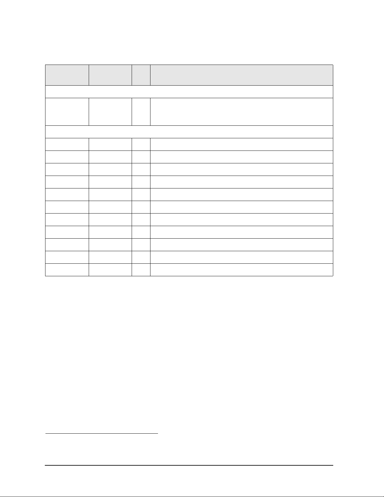
Replaceable Parts FieldFox Analyzer
Replaceable Parts Listings
Front Panel Group
Reference
Designator
Replacement Assemblies
A3 Front
Panel Board
Assembly
Separately Replaceable Individual Parts and Assemblies
A1 N9912-40001 1 Keypad assembly
A2 N9927-60118 1 LCD assembly, 6.5-inch TFT VGA
W11 N9927-60007 1 Cable, A2 LCD to A5 System board
W13 N9927-60005 1 Cable, A2 LCD to A3 Front Panel Interface board
W14 N9927-60009 1 Cable, ribbon, A3 Front Panel Interface board to A5 System board
(1) 1000-1485 1 LCD lens filter
(2) N9927-60011 1 LCD Bracket assembly
(3) 0515-1946 13 Screw, machine, 90-deg flat head, Torx T10, M3.0 x 6 mm
Part Number Qty Description
N9927-60110 1
1
Front Panel Board Assembly—Includes:
A3 front panel interface board
(4) 1990-3613 1 RPG (Rotary Pulse Generator). Includes cable W12, nut, and washer.
(5) W1312-40066 1 RPG knob
(6) 1420-0905 1 Battery, Lithium-ion (For Real Time Clock (RTC) backup.)
1. Each time the FieldFox case is opened for any reason, you must order a Repair and Re-assembly Kit.
See “Miscellaneous Parts” on page 6-13.
6-6 N9927-90003
Page 87
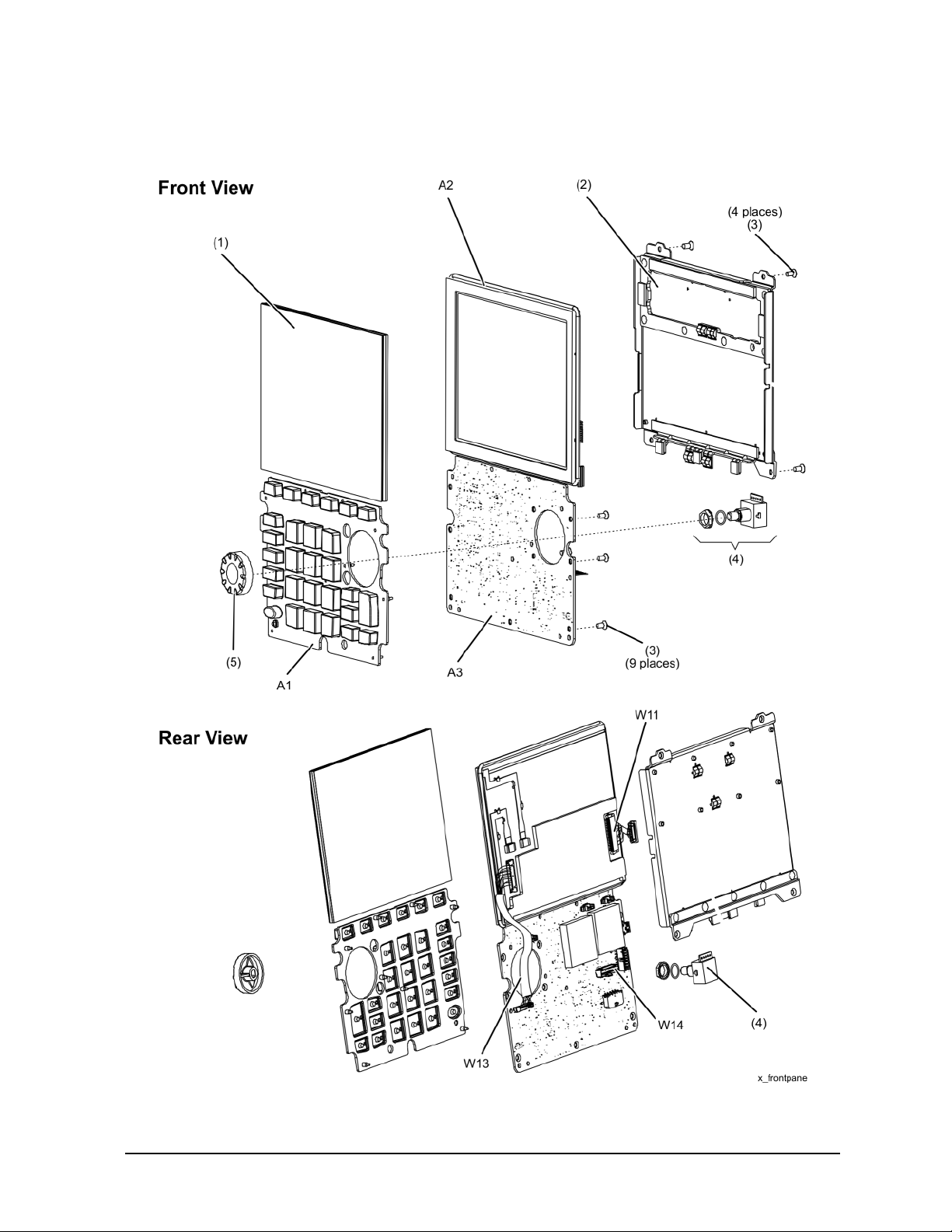
FieldFox Analyzer Replaceable Parts
Replaceable Parts Listings
Figure 6-2 Front Panel Group, Exploded View
N9927-90003 6-7
Page 88
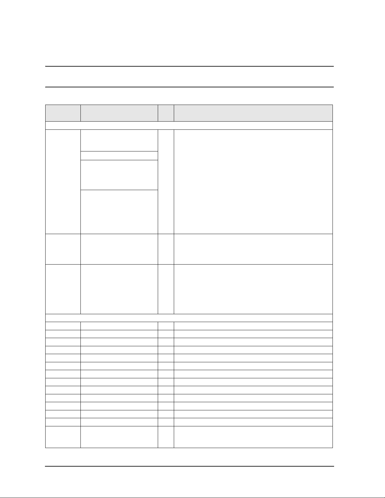
Replaceable Parts FieldFox Analyzer
Replaceable Parts Listings
Measurement Group
NOTE Each time the FieldFox case is opened for any reason, you must order a Repair and
Re-assembly Kit. See “Miscellaneous Parts” on page 6-13.
Reference
Designator
Replacement Assemblies
A4 RF
Assembly
A5 System
Board
Assembly
RF
Top Pa n e l
Assembly
Separately Replaceable Individual Parts and Assemblies
A6 1150-8023 1 SOM Board, 532 MHz processor, 128 MB-SDRAM
A7 N9927-60121 1 RTC Battery Board Assembly
W1 N9927-20028 1 Cable, semi-rigid, Port 1 / RF Output
W2 N9927-20029 1 Cable, semi-rigid, Port 2 / SA RF Input
W3 8121-2029 1 Cable, SMA-MCX, Ref In/Trig In, incl. nut (3) and washer (4)
W4 8121-2029 1 Cable, SMA-MCX, GPS Ant, incl. nut (3) and washer (4)
W17 N9927-60010 1 Cable, RTC Battery board
(1) W1312-40069 2 Connector cover (tethered cap), for Type-N connector
(1) N9927-40013 2 Connector cover (tethered cap), for 3.5 mm connector
(7) N9912-40004 2 Gasket
(8) 8160-0963 2 O-Ring gasket
(9) N9927-60123 4 Type-N Adapter assembly
(9) N9927-60122 4 3.5 mm Adapter assembly
(10) 0515-0372 4
Part Number Qty Description
N9927-60111 N9918A
N9928A
N9938A
N9927-60200 N9913A
N9927-60201 N9914A
N9915A
N9925A
N9935A
N9927-60202 N9916A
N9917A
N9926A
N9927A
N9936A
N9937A
N9927-60112
N9927-60115 1
1
1
1
RF Assembly—Includes:
A4 RF board
Cable W1, semi-rigid, RF OUT (NA port)
Cable W2, semi-rigid, RF IN (SA port)
(8) O-Ring gasket, 8160-0963, qty 2
(9) Adapter coaxial straight, female Type-N to female 3.5 mm, qty 2
(10) Insulator, qty 2
(11) EMI ring, N9927-20064, gty 2
(19) Shield, top, RF
(21) Shield, bottom, RF
(22) Screw, 26 places
System Board Assembly—Includes:
A5 system board, N9927-63002
(13) Screw, 19 places, 0515-5511
(13) Screw, 2 places, 0515-0430
(18) Screw, 4 places, 0515-1940
RF Top Panel Assembly—Includes:
(1) Connector cover (tethered cap), for Type-N connector, qty 2
Connector cover, for SMA connector (W3 & W4), 1401-0245, qty 2
(2) Screw, 0515-2349, 6 places
(5) Overlay, RF
(6) Panel, RF, machined, N9927-20013
(7) Gasket, RF
Screw, machine w/crest cup washer, pan head, Torx T10,
M3.0 x 0.5, 8 mm
(used for Type-N connectors)
6-8 N9927-90003
Page 89
FieldFox Analyzer Replaceable Parts
Replaceable Parts Listings
Reference
Designator
(10) 0515-1035 4
(11) N9912-20033 2 Insulator, w/pad
(12) N9927-20064 2 EMI ring
(14) 0515-1946 2 Screw, machine flat head, Torx T10, M3.0 x 0.5, 6 mm
(15) 1420-0905 1 Battery, Lithium-ion (For Real Time Clock (RTC) backup.)
(16) N9927-60113 1 (25) System board top shield
Part Number Qty Description
Screw, machine, flat head, Torx T10, M3.0 x 0.5, 8 mm
(used for 3.5 mm connectors)
1. Recommended to also order N9927-60133, System Top Shield Assembly
N9927-90003 6-9
Page 90

Replaceable Parts FieldFox Analyzer
Replaceable Parts Listings
Figure 6-3 Measurement Group, Exploded View
6-10 N9927-90003
Page 91
FieldFox Analyzer Replaceable Parts
Replaceable Parts Listings
Case Group
Reference
Designator
(2)
(7)
(8)
(11)
(15)
1
Part Number Qty Description
Replacement Assemblies
Front Enclosure Assembly—Includes:
N9927-60116 1
N9927-60119 1
N9927-60120 1
N9927-60117 1
N9912-60028 1
Separately Replaceable Individual Parts and Assemblies
(2) Front case, W1312-40049, with A1 keypad installed
(3) LCD lens filter
(4) Keypad overlay, N9912-80005
Left Side I/O Panel Assembly—Includes:
Speaker
Right Side I/O Panel Assembly -- Includes:
(9) Battery Door
Rear Enclosure Assembly—Includes:
(11) Rear case
Kick Stand Assembly—Includes:
(15) Kickstand, W1312-40065
(14) Friction hinge and spacer
(13) Screw (for hinge), qty 4
(16) Hinge cover
(17) Screw (for hinge cover), qty 4
(1)
(5)
(6)
(9)
(10)
(12)
Combination Nameplate Set
N9927-80021
N9927-80022
N9927-80013
N9927-80014
N9927-80015
N9927-80016
VNA Nameplate Set
N9927-80011
N9927-80012
N9927-80009
N9927-80010
SA Nameplate Set
N9927-80017
N9927-80018
N9927-80019
N9927-80020
N9912-40006
N9910-80002
W1312-40060
1480-0793
0515-5153
1
1
1
1
1
1
1
1
1
1
1
1
1
1
2 Hole plugs
1 Strap handle
1 Battery door cover
4 Dowel pins
6 Screw, machine w/flat washer, pan head, Torx T10, M3.0 x 0.5, 35 mm
Nameplate, N9913A, 4 GHz
Nameplate, N9914A, 6.5 GHz
Nameplate, N9915A, 9 GHz
Nameplate, N9916A, 14 GHz
Nameplate, N9917A, 18 GHz
Nameplate, N9918A, 26.5 GHz
Nameplate, N9925A, 9 GHz
Nameplate, N9926A, 14 GHz
Nameplate, N9927A, 18 GHz
Nameplate, N9928A, 26.5 GHz
Nameplate, N9935A, 9 GHz
Nameplate, N9936A, 14 GHz
Nameplate, N9937A, 18 GHz
Nameplate, N9938A, 26.5 GHz
1. Each time the FieldFox case is opened for any reason, you must order a Repair and Re-assembly Kit.
See “Miscellaneous Parts” on page 6-13.
N9927-90003 6-11
Page 92

Replaceable Parts FieldFox Analyzer
Replaceable Parts Listings
Reference
Designator
(13)
(14)
(16)
(17)
(18)
Part Number Qty Description
0515-1940
3110-0654
N9912-00003
W1312-40068 1 Hinge cover
0515-2217
N9927-60006
4 Screw, machine w/patch lock, pan head, Torx T8, M2.5x0.45, 6 mm
Friction hinge
1
Spacer
4 Screw, machine, button head, Torx T8, M3.0 x 8 mm
1 Cable assembly, battery
Figure 6-4. Case Group, Exploded View
6-12 N9927-90003
Page 93

FieldFox Analyzer Replaceable Parts
Replaceable Parts Listings
Miscellaneous Parts
Table 6-1 Part Numbers for Miscellaneous Parts and Acce ssories
Description
Repair and Re-assembly Kit
IMPORTANT
This kit is required each time the FieldFox case is opened for any reason.
The kit includes the following items, some or all of which are necessary to re-assemble the internal assemblies
and the case, depending upon the depth of the repair.
Repair and Re-assembly Kit (Includes the following items.)
Screw, machine, 90-deg flat head, Torx T10, M3 x 0.5, 8mm; qty 4
Screw, machine, 90-deg flat head, Torx T10, M3 x 0.5, 6 mm; qty 17
Screw, machine w/patch lock, pan head, Torx T8, M2.5 x 0.45, 6 mm; qty 4
Screw, machine w/crest cup washer, pan head, Torx T10, M3.0 x 0.5 , 8 mm; qty 4
Screw, machine, 90-deg flat head, Torx T10, M3 x 0.5, 14 mm; qty 6
Screw, machine, button head, Torx T8, M3 x 0.5, 8 mm; qty 4
Screw, machine w/flat washer, pan head, Torx T10, M3 x 0.5, 35 mm; qty 6
Rectangular Laser Address Label
O-STRIP RFI Hollow 0.060 in OD, 0.020 in ID; qty 1
Tape, 1/4-inch x 1-inch, for LCD ribbon cable; qty 4
Gasket, Blank Panel, qty 1
Gasket, I/O Panel, qty 1
Cover, hinge
Model or Part
Number
N9927-60130
0515-1035
0515-1946
0515-1940
0515-0372
0515-2349
0515-2217
0515-5153
7121-8321
8160-1725
N9912-20043
N9912-40002
N9912-40003
W1312-40068
Ferrite Cores
Kit containing ferrite cores for use on external LAN cable and headphones cable. N9927-60028
Service Tools
T-8 TORX driver; set to 6 in-lb N/A
T-10 TORX driver; set to 9 in-lb N/A
5/16 inch, open-end torque wrench; set to 10 in-lb
7/16 inch, hex nut wrench or “nut driver”; set to 9 in-lb
9/16 inch, open-end torque wrench; set to 21 in-lb
Documentation
Users’ Guide. Can also be printed from the Agilent Web site. Refer to “Printing Copies of
Documentation from the Web” on page 4.)
Quick Reference Guide N9927-90002
Service Guide. (Not available in printed form. Part number is for reference only. Must be
printed from the Agilent Web site. Refer to “Printing Copies of Documentation from the
Web” on page 4.)
N/A
N/A
N/A
N9927-90001
N9927-90003
N9927-90003 6-13
Page 94

Replaceable Parts FieldFox Analyzer
Replaceable Parts Listings
Table 6-1 Part Numbers for Miscellaneous Parts and Acce ssories (Continued)
Description
Model or Part
Number
ESD Supplies
Adjustable antistatic wrist strap 9300-1367
Antistatic wrist strap grounding cord (5 foot length) 9300-0980
Static control table mat and earth ground wire 9300-0797
ESD heel strap 9300-1126
Battery
1
Battery- Rechargeable Li Ion 11.1V 4.6A-HR 1420-0908
1. Refer to “Battery Disposal” on page 1-7 for instructions on disposing of the old battery.
6-14 N9927-90003
Page 95

7 Repair and Replacement Procedures
N9927-90003 7-1
Page 96
Repair and Replacement Procedures FieldFox Analyzer
Information in This Chapter
Information in This Chapter
This chapter contains procedures for removing and replacing the major assemblies of your Agilent
Technologies FieldFox analyzer.
Section Title Summary of Content Start Page
Personal Safety Warnings Warnings and cautions pertaining to personal safety. Page 7-3
Electrostatic Discharge (ESD)
Protection
Assembly Replacement Sequence A step-by-step procedure for how to identify the
Ta ble of Removal and Replacement
Procedures
Removal and Replacement
Procedures
Post-Repair Procedures A table of the proper tests, verifications, and
Information pertaining to ESD protection. Page 7-3
faulty assembly, replace it with a new one, and
re-adjust your analyzer when done.
A table of removal and replacement procedures and
the corresponding page number where they are
located.
The actual procedures for removing and replacing the
major assemblies in your analyzer.
The procedures occur in assembly reference
designator numerical order.
adjustments to perform on your analyzer after repair.
Page 7-4
Page 7-5
See Table 7-1,
“List of
Procedures,”
on page 7-5
for specific
procedures.
Page 7-44
7-2 N9927-90003
Page 97

FieldFox Analyzer Repair and Replacement Procedures
Personal Safety Warnings
Personal Safety Warnings
WARNING These servicing instructions are for use by qualified personnel only. To avoid
electrical shock, do not perform any servicing unless you are qualified to do so.
WARNING Danger of explosion if battery is incorrectly replaced. Replace only with the same or
equivalent type recommended. Discard used batteries according to manufacturer’s
instructions.
Safety Earth Ground
WARNING This is a Safety Class I product (provided with a protective earthing ground
incorporated in the power cord). The mains plug shall only be inserted in a socket
outlet provided with a protective earth contact. Any interruption of the protective
conductor, inside or outside of the instrument, will make the instrument dangerous.
Intentional interruption is prohibited.
CAUTION Always use the three-prong AC power cord supplied with this product. Failure to ensure
adequate grounding by not using this cord may cause produ ct damage.
Electrostatic Discharge (ESD) Protection
CAUTION Many of the assemblies in this instrument are very susceptible to damage from
electrostatic discharge (ESD). Perform the following procedures only at a static-safe
workstation and wear a grounded wrist strap.
This is important. If not properly protected against, electrostatic discharge can seriously
damage your analyzer, resulting in costly repair.
To reduce the chance of electrostatic discharge, follow all of the recommendations
outlined in “Electrostatic Discharge Protection” on page 1-5, for all of the procedures in
this chapter.
N9927-90003 7-3
Page 98

Repair and Replacement Procedures FieldFox Analyzer
Assembly Replacement Sequence
Assembly Replacement Sequence
The following steps show the sequence that you should follow to replace an assembly in the FieldFox
analyzer.
Step 1. Identify the faulty group. Begin with Chapter 4 , “Troubleshooting.”
Step 2. Order a replacement assembly. Refer to Chapter 6 , “Replaceable Parts.”
Step 3. Replace the faulty assembly and determine what adjustments are necessary. Refer to
“Post-Repair Procedures” in this chapter.
Step 4. Perform the necessary adjustments. Refer to Chapter 3 , “Tests and Adjustments.”
Step 5. Perform the necessary performance tests. Refer to Chapter 3 , “Tests and Adjustments.”
7-4 N9927-90003
Page 99
FieldFox Analyzer Repair and Replacement Procedures
Removal and Replacement Procedures
Removal and Replacement Procedures
Table 7-1 List of Procedures
Reference
Designator
or Name
Main battery Primary power battery Page 7-6
Case parts All enclosure case parts Page 7-8
A1 Keypad Page 7-17
RPG RPG (part of front panel group) Page 7-21
A2 LCD Page 7-23
Assembly Description Location
A3 Front panel interface board Page 7-25
Measurement
Group
RF Top Panel RF Top Panel Assembly Page 7-29
RF Connectors
and Cables
RTC battery
A6
A5 System board Page 7-35
A4 RF board Page 7-39
Measurement Group Assemblies as One Unit Page 7-27
RF Connectors and Cables (part of RF board) Page 7-30
Backup battery for real time clock
(Located on RTC board attached to the A5 System board shield.)
SOM board Page 7-32
Page 7-31
N9927-90003 7-5
Page 100

Repair and Replacement Procedures FieldFox Analyzer
Removing and Replacing the Main Battery
Removing and Replacing the Main Battery
Tools Required
•None
IMPORTANTRefer to “Battery Disposal” on page 1-7 for important instructions on disposing of the old
battery.
Replacing the Main Battery
1. Disconnect the power cord.
2. Refer to Figure 7-1. Remove the battery compartment door by pushing in on the detent and then
sliding the door downwards.
3. Note the orientation of the battery for installation of the replacement.
4. Remove the old battery and install the new battery in the battery compartment.
5. Reinstall the battery compartment door by aligning it in position and then sliding it upwards until an
audible click is heard.
7-6 N9927-90003
 Loading...