

Page 1

Agilent X-Series
Signal Analyzer
This manual provides documentation for the
following X-Series Analyzers:
PXA Signal Analyzer N9030A
MXA Signal Analyzer N9020A
EXA Signal Analyzer N9010A
N9061A
Remote Language
Compatibility Guide
Page 2

Notices
© Agilent Technologies, Inc. 2008, 2009
No part of this manual may be reproduced
in any form or by any means (including
electronic storage and retrieval or translation into a foreign language) without prior
agreement and written consent from Agilent Technologies, Inc. as governed by
United States and international copyright
laws.
Trademark
Acknowledgements
Microsoft® is a U.S. registered
trademark of Microsoft Corporation.
Windows
U.S. registered trademarks of
Microsoft Corporation.
Adobe Reader
trademark of Adobe System
Incorporated.
Java™ is a U.S. trademark of Sun
Microsystems, Inc.
MATLAB® is a U.S. registered
trademark of Math Works, Inc.
Norton Ghost™ is a U.S. trademark
of Symantec Corporation.
®
and MS Windows® are
®
is a U.S. registered
Manual Part Number
N9020-90119
Supersedes: August 2009
Print Date
October 2009
Printed in USA
Agilent Technologies, Inc.
1400 Fountaingrove Parkway
Santa Rosa, CA 95403
Warranty
The material contained in this document is provided “as is,” and is
subject to being changed, without
notice, in future editions. Further,
to the maximum extent permitted
by applicable law, Agilent disclaims all warranties, either
express or implied, with regard to
this manual and any information
contained herein, including but not
limited to the implied warranties of
merchantability and fitness for a
particular purpose. Agilent shall
not be liable for errors or for incidental or consequential damages in
connection with the furnishing, use,
or performance of this document or
of any information contained
herein. Should Agilent and the user
have a separate written agreement
with warranty terms covering the
material in this document that conflict with these terms, the warranty
terms in the separate agreement
shall control.
Technology Licenses
The hardware and/or software described
in this document are furnished under a
license and may be used or copied only in
accordance with the terms of such license.
Restricted Rights Legend
If software is for use in the performance
of a U.S. Government prime contract or
subcontract, Software is delivered and
licensed as “Commercial computer software” as defined in DF AR 252.227-7014
(June 1995), or as a “commercial item” as
defined in F AR 2.101(a) or as “Restricted
computer software” as defined in FAR
52.227-19 (June 1987) or any equivalent
agency regulation or contract clause. Use,
duplication or disclosure of Software is
subject to Agilent Technologies’ standard commercial license terms, and nonDOD Departments and Agencies of the
U.S. Government will receive no greater
than Restricted Rights as defined in FAR
52.227-19(c)(1-2) (June 1987). U.S. Government users will receive no greater than
Limited Rights as defined in FAR 52.22714 (June 1987) or DFAR 252.227-7015
(b)(2) (November 1995), as applicable in
any technical data.
Safety Notices
CAUTION
A CAUTION notice denotes a
hazard. It calls attention to an
operating procedure, practice, or
the like that, if not correctly performed or adhered to, could result
in damage to the product or loss of
important data. Do not proceed
beyond a CAUTION notice until
the indicated conditions are fully
understood and met.
WARNING
A WARNING notice denotes a
hazard. It calls attention to an
operating procedure, practice,
or the like that, if not correctly
performed or adhered to, could
result in personal injury or
death. Do not proceed beyond a
WARNING notice until the
indicated conditions are fully
understood and met.
2
Page 3

Warranty
This Agilent technologies instrument product is warranted against defects in material and workmanship for
a period of one year from the date of shipment. During the warranty period, Agilent Technologies will, at
its option, either repair or replace products that prove to be defective.
For warranty service or repair, this product must be returned to a service facility designated by Agilent
Technologies. Buyer shall prepay shipping charges to Agilent Technologies and Agilent Technologies
shall pay shipping charges to return the product to Buyer. However, Buyer shall pay all shipping charges,
duties, and taxes for products returned to Agilent Technologies from another country.
Where to Find the Latest Information
Documentation is updated periodically. For the latest information about this analyzer, including firmware
upgrades, application information, and product information, see the following URLs:
http://www.agilent.com/find/pxa
http://www.agilent.com/find/mxa
http://www.agilent.com/find/exa
To receive the latest updates by email, subscribe to Agilent Email Updates:
http://www.agilent.com/find/emailupdates
Information on preventing analyzer damage can be found at:
http://www.agilent.com/find/tips
3
Page 4

4
Page 5

Contents
1. Getting Started
N9061A Application Description . . . . . . . . . . . . . . . . . . . . . . . . . . . . . . . . . . . . . . . . . . . . . . . . . . . . . . . . 18
Documentation for the N9061A application . . . . . . . . . . . . . . . . . . . . . . . . . . . . . . . . . . . . . . . . . . . . . . . . 19
N9061A General Rules and Limitations . . . . . . . . . . . . . . . . . . . . . . . . . . . . . . . . . . . . . . . . . . . . . . . . . . . 20
Hardware and Firmware Requirements for N9061A . . . . . . . . . . . . . . . . . . . . . . . . . . . . . . . . . . . . . . . . . . 23
Installing the N9061A application . . . . . . . . . . . . . . . . . . . . . . . . . . . . . . . . . . . . . . . . . . . . . . . . . . . . . . . . 25
Setting up N9061A on the X-Series Analyzer . . . . . . . . . . . . . . . . . . . . . . . . . . . . . . . . . . . . . . . . . . . . . . . 27
Running Software that Requires SCPI Commands . . . . . . . . . . . . . . . . . . . . . . . . . . . . . . . . . . . . . . . . . . . 38
Service and Calibration . . . . . . . . . . . . . . . . . . . . . . . . . . . . . . . . . . . . . . . . . . . . . . . . . . . . . . . . . . . . . . . . 40
2. Legacy Analyzer Command List
Table of All Legacy Analyzer Commands . . . . . . . . . . . . . . . . . . . . . . . . . . . . . . . . . . . . . . . . . . . . . . . . . . 42
3. Hints and Tips
Hints and Tips . . . . . . . . . . . . . . . . . . . . . . . . . . . . . . . . . . . . . . . . . . . . . . . . . . . . . . . . . . . . . . . . . . . . . . . 72
4. Programming Commands
Command Syntax . . . . . . . . . . . . . . . . . . . . . . . . . . . . . . . . . . . . . . . . . . . . . . . . . . . . . . . . . . . . . . . . . . . . . 76
Programming Command Descriptions . . . . . . . . . . . . . . . . . . . . . . . . . . . . . . . . . . . . . . . . . . . . . . . . . . . . . 78
A1 [one]
Clear Write for Trace A . . . . . . . . . . . . . . . . . . . . . . . . . . . . . . . . . . . . . . . . . . . . . . . . . . . . . . . . . . . . . . . . 79
A2 [two]
Maximum Hold for Trace A . . . . . . . . . . . . . . . . . . . . . . . . . . . . . . . . . . . . . . . . . . . . . . . . . . . . . . . . . . . . 80
A3 [three]
View Mode for Trace A . . . . . . . . . . . . . . . . . . . . . . . . . . . . . . . . . . . . . . . . . . . . . . . . . . . . . . . . . . . . . . . . 81
A4 [four]
Blank Trace A . . . . . . . . . . . . . . . . . . . . . . . . . . . . . . . . . . . . . . . . . . . . . . . . . . . . . . . . . . . . . . . . . . . . . . . 82
ACPALPHA
Adjacent Channel Power Alpha Weighting . . . . . . . . . . . . . . . . . . . . . . . . . . . . . . . . . . . . . . . . . . . . . . . . . 83
ACPALTCH
Adjacent Channel Power Alternate Channels . . . . . . . . . . . . . . . . . . . . . . . . . . . . . . . . . . . . . . . . . . . . . . . 84
ACPBRPER
Adjacent Channel Power Burst Period . . . . . . . . . . . . . . . . . . . . . . . . . . . . . . . . . . . . . . . . . . . . . . . . . . . . 85
ACPBRWID
Adjacent Channel Power Burst Width . . . . . . . . . . . . . . . . . . . . . . . . . . . . . . . . . . . . . . . . . . . . . . . . . . . . . 86
ACPBW
Adjacent Channel Power Bandwidth . . . . . . . . . . . . . . . . . . . . . . . . . . . . . . . . . . . . . . . . . . . . . . . . . . . . . . 87
ACPCOMPUTE
Adjacent Channel Power Compute . . . . . . . . . . . . . . . . . . . . . . . . . . . . . . . . . . . . . . . . . . . . . . . . . . . . . . . 88
ACPFRQWT
Adjacent Channel Power Frequency Weighting . . . . . . . . . . . . . . . . . . . . . . . . . . . . . . . . . . . . . . . . . . . . . 89
ACPLOWER
Lower Adjacent Channel Power . . . . . . . . . . . . . . . . . . . . . . . . . . . . . . . . . . . . . . . . . . . . . . . . . . . . . . . . . 90
ACPMAX
Maximum Adjacent Channel Power . . . . . . . . . . . . . . . . . . . . . . . . . . . . . . . . . . . . . . . . . . . . . . . . . . . . . . 91
ACPMEAS
Measure Adjacent Channel Power . . . . . . . . . . . . . . . . . . . . . . . . . . . . . . . . . . . . . . . . . . . . . . . . . . . . . . . . 92
ACPMSTATE
5
Page 6

Contents
Adjacent Channel Power Measurement State . . . . . . . . . . . . . . . . . . . . . . . . . . . . . . . . . . . . . . . . . . . . . . . 93
ACPPWRTX
Adjacent Channel Power Total Power Transmitted . . . . . . . . . . . . . . . . . . . . . . . . . . . . . . . . . . . . . . . . . . . 94
ACPRSLTS
Adjacent Channel Power Measurement Results . . . . . . . . . . . . . . . . . . . . . . . . . . . . . . . . . . . . . . . . . . . . . 95
ACPSP
Adjacent Channel Power Channel Spacing . . . . . . . . . . . . . . . . . . . . . . . . . . . . . . . . . . . . . . . . . . . . . . . . . 96
ACPT
Adjacent Channel Power T Weighting . . . . . . . . . . . . . . . . . . . . . . . . . . . . . . . . . . . . . . . . . . . . . . . . . . . . 97
ACPUPPER
Upper Adjacent Channel Power . . . . . . . . . . . . . . . . . . . . . . . . . . . . . . . . . . . . . . . . . . . . . . . . . . . . . . . . . 98
ADJALL
LO and IF Adjustments . . . . . . . . . . . . . . . . . . . . . . . . . . . . . . . . . . . . . . . . . . . . . . . . . . . . . . . . . . . . . . . . 99
AMB
A minus B into A . . . . . . . . . . . . . . . . . . . . . . . . . . . . . . . . . . . . . . . . . . . . . . . . . . . . . . . . . . . . . . . . . . . . 100
AMBPL
(A minus B) plus Display Line into A . . . . . . . . . . . . . . . . . . . . . . . . . . . . . . . . . . . . . . . . . . . . . . . . . . . . 101
ANNOT
Annotation . . . . . . . . . . . . . . . . . . . . . . . . . . . . . . . . . . . . . . . . . . . . . . . . . . . . . . . . . . . . . . . . . . . . . . . . . 102
APB
Trace A Plus Trace B to A . . . . . . . . . . . . . . . . . . . . . . . . . . . . . . . . . . . . . . . . . . . . . . . . . . . . . . . . . . . . . 103
AT
Input Attenuation . . . . . . . . . . . . . . . . . . . . . . . . . . . . . . . . . . . . . . . . . . . . . . . . . . . . . . . . . . . . . . . . . . . . 104
AUNITS
Absolute Amplitude Units . . . . . . . . . . . . . . . . . . . . . . . . . . . . . . . . . . . . . . . . . . . . . . . . . . . . . . . . . . . . . 106
AUTOCPL
Auto Coupled . . . . . . . . . . . . . . . . . . . . . . . . . . . . . . . . . . . . . . . . . . . . . . . . . . . . . . . . . . . . . . . . . . . . . . . 108
AXB
Exchange Trace A and Trace B . . . . . . . . . . . . . . . . . . . . . . . . . . . . . . . . . . . . . . . . . . . . . . . . . . . . . . . . . 109
B1 [one]
Clear Write for Trace B . . . . . . . . . . . . . . . . . . . . . . . . . . . . . . . . . . . . . . . . . . . . . . . . . . . . . . . . . . . . . . . 110
B2 [two]
Maximum Hold for Trace B . . . . . . . . . . . . . . . . . . . . . . . . . . . . . . . . . . . . . . . . . . . . . . . . . . . . . . . . . . . 111
B3 [three]
View Mode for Trace B . . . . . . . . . . . . . . . . . . . . . . . . . . . . . . . . . . . . . . . . . . . . . . . . . . . . . . . . . . . . . . . 112
B4 [four]
Blank Trace B . . . . . . . . . . . . . . . . . . . . . . . . . . . . . . . . . . . . . . . . . . . . . . . . . . . . . . . . . . . . . . . . . . . . . . 113
BL
Trace B minus Display Line to Trace B . . . . . . . . . . . . . . . . . . . . . . . . . . . . . . . . . . . . . . . . . . . . . . . . . . 114
BLANK
Blank Trace . . . . . . . . . . . . . . . . . . . . . . . . . . . . . . . . . . . . . . . . . . . . . . . . . . . . . . . . . . . . . . . . . . . . . . . . 115
BML
Trace B Minus Display Line . . . . . . . . . . . . . . . . . . . . . . . . . . . . . . . . . . . . . . . . . . . . . . . . . . . . . . . . . . . 116
BTC
Transfer Trace B to Trace C . . . . . . . . . . . . . . . . . . . . . . . . . . . . . . . . . . . . . . . . . . . . . . . . . . . . . . . . . . . 117
BXC
Exchange Trace B and Trace C . . . . . . . . . . . . . . . . . . . . . . . . . . . . . . . . . . . . . . . . . . . . . . . . . . . . . . . . . 118
C1 [one]
Set A Minus B Mode Off . . . . . . . . . . . . . . . . . . . . . . . . . . . . . . . . . . . . . . . . . . . . . . . . . . . . . . . . . . . . . 119
6
Page 7

Contents
C2 [two]
A Minus B Into A . . . . . . . . . . . . . . . . . . . . . . . . . . . . . . . . . . . . . . . . . . . . . . . . . . . . . . . . . . . . . . . . . . . 120
CA
Couple Attenuation . . . . . . . . . . . . . . . . . . . . . . . . . . . . . . . . . . . . . . . . . . . . . . . . . . . . . . . . . . . . . . . . . . 121
CARROFF
Carrier Off Power . . . . . . . . . . . . . . . . . . . . . . . . . . . . . . . . . . . . . . . . . . . . . . . . . . . . . . . . . . . . . . . . . . . 122
CARRON
Carrier On Power . . . . . . . . . . . . . . . . . . . . . . . . . . . . . . . . . . . . . . . . . . . . . . . . . . . . . . . . . . . . . . . . . . . . 123
CF
Center Frequency . . . . . . . . . . . . . . . . . . . . . . . . . . . . . . . . . . . . . . . . . . . . . . . . . . . . . . . . . . . . . . . . . . . . 124
CHANNEL
Channel Selection . . . . . . . . . . . . . . . . . . . . . . . . . . . . . . . . . . . . . . . . . . . . . . . . . . . . . . . . . . . . . . . . . . . 126
CHANPWR
Channel Power . . . . . . . . . . . . . . . . . . . . . . . . . . . . . . . . . . . . . . . . . . . . . . . . . . . . . . . . . . . . . . . . . . . . . . 127
CHPWRBW
Channel Power Bandwidth . . . . . . . . . . . . . . . . . . . . . . . . . . . . . . . . . . . . . . . . . . . . . . . . . . . . . . . . . . . . 128
CLRAVG
Clear Average . . . . . . . . . . . . . . . . . . . . . . . . . . . . . . . . . . . . . . . . . . . . . . . . . . . . . . . . . . . . . . . . . . . . . . . 129
CLRW
Clear Write . . . . . . . . . . . . . . . . . . . . . . . . . . . . . . . . . . . . . . . . . . . . . . . . . . . . . . . . . . . . . . . . . . . . . . . . . 130
CONTS
Continuous Sweep . . . . . . . . . . . . . . . . . . . . . . . . . . . . . . . . . . . . . . . . . . . . . . . . . . . . . . . . . . . . . . . . . . . 132
COUPLE
Input Coupling . . . . . . . . . . . . . . . . . . . . . . . . . . . . . . . . . . . . . . . . . . . . . . . . . . . . . . . . . . . . . . . . . . . . . . 133
CR
Couple Resolution Bandwidth . . . . . . . . . . . . . . . . . . . . . . . . . . . . . . . . . . . . . . . . . . . . . . . . . . . . . . . . . . 134
CS
Couple Frequency Step Size . . . . . . . . . . . . . . . . . . . . . . . . . . . . . . . . . . . . . . . . . . . . . . . . . . . . . . . . . . . 135
CT
Couple Sweep Time . . . . . . . . . . . . . . . . . . . . . . . . . . . . . . . . . . . . . . . . . . . . . . . . . . . . . . . . . . . . . . . . . . 136
CV
Couple Video Bandwidth . . . . . . . . . . . . . . . . . . . . . . . . . . . . . . . . . . . . . . . . . . . . . . . . . . . . . . . . . . . . . . 137
DA
Display Address . . . . . . . . . . . . . . . . . . . . . . . . . . . . . . . . . . . . . . . . . . . . . . . . . . . . . . . . . . . . . . . . . . . . . 138
DELMKBW
Occupied Power Bandwidth Within Delta Marker . . . . . . . . . . . . . . . . . . . . . . . . . . . . . . . . . . . . . . . . . . 139
DET
Detection Mode . . . . . . . . . . . . . . . . . . . . . . . . . . . . . . . . . . . . . . . . . . . . . . . . . . . . . . . . . . . . . . . . . . . . . 140
DL
Display Line . . . . . . . . . . . . . . . . . . . . . . . . . . . . . . . . . . . . . . . . . . . . . . . . . . . . . . . . . . . . . . . . . . . . . . . . 141
DLE
Display Line Enable . . . . . . . . . . . . . . . . . . . . . . . . . . . . . . . . . . . . . . . . . . . . . . . . . . . . . . . . . . . . . . . . . . 143
DLYSWP
Delay Sweep . . . . . . . . . . . . . . . . . . . . . . . . . . . . . . . . . . . . . . . . . . . . . . . . . . . . . . . . . . . . . . . . . . . . . . . 144
DONE
Done . . . . . . . . . . . . . . . . . . . . . . . . . . . . . . . . . . . . . . . . . . . . . . . . . . . . . . . . . . . . . . . . . . . . . . . . . . . . . . 145
DR
Display Read . . . . . . . . . . . . . . . . . . . . . . . . . . . . . . . . . . . . . . . . . . . . . . . . . . . . . . . . . . . . . . . . . . . . . . . 146
E1[one]
7
Page 8

Contents
Peak Marker . . . . . . . . . . . . . . . . . . . . . . . . . . . . . . . . . . . . . . . . . . . . . . . . . . . . . . . . . . . . . . . . . . . . . . . . 147
E2 [two]
Marker to Center Frequency . . . . . . . . . . . . . . . . . . . . . . . . . . . . . . . . . . . . . . . . . . . . . . . . . . . . . . . . . . . 148
E3 [three]
Delta Marker Step Size . . . . . . . . . . . . . . . . . . . . . . . . . . . . . . . . . . . . . . . . . . . . . . . . . . . . . . . . . . . . . . . 149
E4 [four]
Marker to Reference Level . . . . . . . . . . . . . . . . . . . . . . . . . . . . . . . . . . . . . . . . . . . . . . . . . . . . . . . . . . . . 150
EDITDONE
Edit Done . . . . . . . . . . . . . . . . . . . . . . . . . . . . . . . . . . . . . . . . . . . . . . . . . . . . . . . . . . . . . . . . . . . . . . . . . . 151
ERR
Error . . . . . . . . . . . . . . . . . . . . . . . . . . . . . . . . . . . . . . . . . . . . . . . . . . . . . . . . . . . . . . . . . . . . . . . . . . . . . . 152
ET
Elapsed Time . . . . . . . . . . . . . . . . . . . . . . . . . . . . . . . . . . . . . . . . . . . . . . . . . . . . . . . . . . . . . . . . . . . . . . . 154
EX
Exchange Trace A and Trace B . . . . . . . . . . . . . . . . . . . . . . . . . . . . . . . . . . . . . . . . . . . . . . . . . . . . . . . . . 155
FA
Start Frequency . . . . . . . . . . . . . . . . . . . . . . . . . . . . . . . . . . . . . . . . . . . . . . . . . . . . . . . . . . . . . . . . . . . . . 156
FB
Stop Frequency . . . . . . . . . . . . . . . . . . . . . . . . . . . . . . . . . . . . . . . . . . . . . . . . . . . . . . . . . . . . . . . . . . . . . 157
FDSP
Frequency Display Off . . . . . . . . . . . . . . . . . . . . . . . . . . . . . . . . . . . . . . . . . . . . . . . . . . . . . . . . . . . . . . . 158
FOFFSET
Frequency Offset . . . . . . . . . . . . . . . . . . . . . . . . . . . . . . . . . . . . . . . . . . . . . . . . . . . . . . . . . . . . . . . . . . . . 159
FPKA
Fast Preselector Peak . . . . . . . . . . . . . . . . . . . . . . . . . . . . . . . . . . . . . . . . . . . . . . . . . . . . . . . . . . . . . . . . . 161
FREF
Frequency Reference . . . . . . . . . . . . . . . . . . . . . . . . . . . . . . . . . . . . . . . . . . . . . . . . . . . . . . . . . . . . . . . . . 162
FS
Full Span . . . . . . . . . . . . . . . . . . . . . . . . . . . . . . . . . . . . . . . . . . . . . . . . . . . . . . . . . . . . . . . . . . . . . . . . . . 163
GATE
Gate . . . . . . . . . . . . . . . . . . . . . . . . . . . . . . . . . . . . . . . . . . . . . . . . . . . . . . . . . . . . . . . . . . . . . . . . . . . . . . 166
GATECTL
Gate Control . . . . . . . . . . . . . . . . . . . . . . . . . . . . . . . . . . . . . . . . . . . . . . . . . . . . . . . . . . . . . . . . . . . . . . . 167
GD
Gate Delay . . . . . . . . . . . . . . . . . . . . . . . . . . . . . . . . . . . . . . . . . . . . . . . . . . . . . . . . . . . . . . . . . . . . . . . . . 168
GL
Gate Length . . . . . . . . . . . . . . . . . . . . . . . . . . . . . . . . . . . . . . . . . . . . . . . . . . . . . . . . . . . . . . . . . . . . . . . . 169
GP
Gate Polarity . . . . . . . . . . . . . . . . . . . . . . . . . . . . . . . . . . . . . . . . . . . . . . . . . . . . . . . . . . . . . . . . . . . . . . . 170
GRAT
Graticule . . . . . . . . . . . . . . . . . . . . . . . . . . . . . . . . . . . . . . . . . . . . . . . . . . . . . . . . . . . . . . . . . . . . . . . . . . 171
HD
Hold Data Entry . . . . . . . . . . . . . . . . . . . . . . . . . . . . . . . . . . . . . . . . . . . . . . . . . . . . . . . . . . . . . . . . . . . . . 172
I1 [one]
Set RF Coupling to DC . . . . . . . . . . . . . . . . . . . . . . . . . . . . . . . . . . . . . . . . . . . . . . . . . . . . . . . . . . . . . . . 173
I2 [two]
Set RF Coupling to AC . . . . . . . . . . . . . . . . . . . . . . . . . . . . . . . . . . . . . . . . . . . . . . . . . . . . . . . . . . . . . . . 175
ID
Identify . . . . . . . . . . . . . . . . . . . . . . . . . . . . . . . . . . . . . . . . . . . . . . . . . . . . . . . . . . . . . . . . . . . . . . . . . . . 177
8
Page 9

Contents
IP
Instrument Preset . . . . . . . . . . . . . . . . . . . . . . . . . . . . . . . . . . . . . . . . . . . . . . . . . . . . . . . . . . . . . . . . . . . . 178
KS,
Mixer Level . . . . . . . . . . . . . . . . . . . . . . . . . . . . . . . . . . . . . . . . . . . . . . . . . . . . . . . . . . . . . . . . . . . . . . . . 179
KS=
8566A/B: Automatic Preselector Tracking
8568A/B: Marker Counter Resolution . . . . . . . . . . . . . . . . . . . . . . . . . . . . . . . . . . . . . . . . . . . . . . . . . . . . 180
KS(
Lock Registers . . . . . . . . . . . . . . . . . . . . . . . . . . . . . . . . . . . . . . . . . . . . . . . . . . . . . . . . . . . . . . . . . . . . . . 181
KS)
Unlock Registers . . . . . . . . . . . . . . . . . . . . . . . . . . . . . . . . . . . . . . . . . . . . . . . . . . . . . . . . . . . . . . . . . . . . 182
KSA
Amplitude in dBm . . . . . . . . . . . . . . . . . . . . . . . . . . . . . . . . . . . . . . . . . . . . . . . . . . . . . . . . . . . . . . . . . . . 183
KSa
Normal Detection . . . . . . . . . . . . . . . . . . . . . . . . . . . . . . . . . . . . . . . . . . . . . . . . . . . . . . . . . . . . . . . . . . . . 184
KSB
Amplitude in dBmV . . . . . . . . . . . . . . . . . . . . . . . . . . . . . . . . . . . . . . . . . . . . . . . . . . . . . . . . . . . . . . . . . . 185
KSb
Positive Peak Detection . . . . . . . . . . . . . . . . . . . . . . . . . . . . . . . . . . . . . . . . . . . . . . . . . . . . . . . . . . . . . . . 186
KSC
Amplitude in dBuV . . . . . . . . . . . . . . . . . . . . . . . . . . . . . . . . . . . . . . . . . . . . . . . . . . . . . . . . . . . . . . . . . . 187
KSc
A Plus B to A . . . . . . . . . . . . . . . . . . . . . . . . . . . . . . . . . . . . . . . . . . . . . . . . . . . . . . . . . . . . . . . . . . . . . . . 188
KSD
Amplitude in Volts . . . . . . . . . . . . . . . . . . . . . . . . . . . . . . . . . . . . . . . . . . . . . . . . . . . . . . . . . . . . . . . . . . . 189
KSd
Negative Peak Detection . . . . . . . . . . . . . . . . . . . . . . . . . . . . . . . . . . . . . . . . . . . . . . . . . . . . . . . . . . . . . . 190
KSE
Title Mode . . . . . . . . . . . . . . . . . . . . . . . . . . . . . . . . . . . . . . . . . . . . . . . . . . . . . . . . . . . . . . . . . . . . . . . . . 191
KSe
Sample Detection . . . . . . . . . . . . . . . . . . . . . . . . . . . . . . . . . . . . . . . . . . . . . . . . . . . . . . . . . . . . . . . . . . . . 192
KSG
Video Averaging On . . . . . . . . . . . . . . . . . . . . . . . . . . . . . . . . . . . . . . . . . . . . . . . . . . . . . . . . . . . . . . . . . 193
KSg
Display Off . . . . . . . . . . . . . . . . . . . . . . . . . . . . . . . . . . . . . . . . . . . . . . . . . . . . . . . . . . . . . . . . . . . . . . . . . 194
KSH
Video Averaging Off . . . . . . . . . . . . . . . . . . . . . . . . . . . . . . . . . . . . . . . . . . . . . . . . . . . . . . . . . . . . . . . . . 195
KSh
Display On . . . . . . . . . . . . . . . . . . . . . . . . . . . . . . . . . . . . . . . . . . . . . . . . . . . . . . . . . . . . . . . . . . . . . . . . . 196
KSi
Exchange Trace B and Trace C . . . . . . . . . . . . . . . . . . . . . . . . . . . . . . . . . . . . . . . . . . . . . . . . . . . . . . . . . 197
KSj
View Trace C . . . . . . . . . . . . . . . . . . . . . . . . . . . . . . . . . . . . . . . . . . . . . . . . . . . . . . . . . . . . . . . . . . . . . . . 198
KSK
Marker to Next Peak . . . . . . . . . . . . . . . . . . . . . . . . . . . . . . . . . . . . . . . . . . . . . . . . . . . . . . . . . . . . . . . . . 199
KSk
Blank Trace C . . . . . . . . . . . . . . . . . . . . . . . . . . . . . . . . . . . . . . . . . . . . . . . . . . . . . . . . . . . . . . . . . . . . . . 200
KSL
Marker Noise Off . . . . . . . . . . . . . . . . . . . . . . . . . . . . . . . . . . . . . . . . . . . . . . . . . . . . . . . . . . . . . . . . . . . . 201
9
Page 10

Contents
KSl
Transfer Trace B to Trace C . . . . . . . . . . . . . . . . . . . . . . . . . . . . . . . . . . . . . . . . . . . . . . . . . . . . . . . . . . . 202
KSM
Marker Noise On . . . . . . . . . . . . . . . . . . . . . . . . . . . . . . . . . . . . . . . . . . . . . . . . . . . . . . . . . . . . . . . . . . . . 203
KSm
Graticule Off . . . . . . . . . . . . . . . . . . . . . . . . . . . . . . . . . . . . . . . . . . . . . . . . . . . . . . . . . . . . . . . . . . . . . . . 204
KSN
Marker Minimum . . . . . . . . . . . . . . . . . . . . . . . . . . . . . . . . . . . . . . . . . . . . . . . . . . . . . . . . . . . . . . . . . . . 205
KSn
Graticule On . . . . . . . . . . . . . . . . . . . . . . . . . . . . . . . . . . . . . . . . . . . . . . . . . . . . . . . . . . . . . . . . . . . . . . . 206
KSO
Marker Span . . . . . . . . . . . . . . . . . . . . . . . . . . . . . . . . . . . . . . . . . . . . . . . . . . . . . . . . . . . . . . . . . . . . . . . 207
KSo
Annotation Off . . . . . . . . . . . . . . . . . . . . . . . . . . . . . . . . . . . . . . . . . . . . . . . . . . . . . . . . . . . . . . . . . . . . . . 208
KSp
Annotation On . . . . . . . . . . . . . . . . . . . . . . . . . . . . . . . . . . . . . . . . . . . . . . . . . . . . . . . . . . . . . . . . . . . . . . 209
KST
Fast Preset . . . . . . . . . . . . . . . . . . . . . . . . . . . . . . . . . . . . . . . . . . . . . . . . . . . . . . . . . . . . . . . . . . . . . . . . . 210
KSV
Frequency Offset . . . . . . . . . . . . . . . . . . . . . . . . . . . . . . . . . . . . . . . . . . . . . . . . . . . . . . . . . . . . . . . . . . . . 211
KSx
External Trigger . . . . . . . . . . . . . . . . . . . . . . . . . . . . . . . . . . . . . . . . . . . . . . . . . . . . . . . . . . . . . . . . . . . . . 212
KSy
Video Trigger . . . . . . . . . . . . . . . . . . . . . . . . . . . . . . . . . . . . . . . . . . . . . . . . . . . . . . . . . . . . . . . . . . . . . . . 213
KSZ
Reference Level Offset . . . . . . . . . . . . . . . . . . . . . . . . . . . . . . . . . . . . . . . . . . . . . . . . . . . . . . . . . . . . . . . 214
L0 [zero]
Display Line Off . . . . . . . . . . . . . . . . . . . . . . . . . . . . . . . . . . . . . . . . . . . . . . . . . . . . . . . . . . . . . . . . . . . . 215
LF
Low Frequency Preset . . . . . . . . . . . . . . . . . . . . . . . . . . . . . . . . . . . . . . . . . . . . . . . . . . . . . . . . . . . . . . . . 216
LG
Logarithmic Scale . . . . . . . . . . . . . . . . . . . . . . . . . . . . . . . . . . . . . . . . . . . . . . . . . . . . . . . . . . . . . . . . . . . 217
LIMF
Limit Line Frequency Value . . . . . . . . . . . . . . . . . . . . . . . . . . . . . . . . . . . . . . . . . . . . . . . . . . . . . . . . . . . 219
LIMIFAIL
Limits Failed . . . . . . . . . . . . . . . . . . . . . . . . . . . . . . . . . . . . . . . . . . . . . . . . . . . . . . . . . . . . . . . . . . . . . . . 220
LIMIPURGE
Delete Current Limit Line . . . . . . . . . . . . . . . . . . . . . . . . . . . . . . . . . . . . . . . . . . . . . . . . . . . . . . . . . . . . . 221
LIMIREL
Relative Limit Lines . . . . . . . . . . . . . . . . . . . . . . . . . . . . . . . . . . . . . . . . . . . . . . . . . . . . . . . . . . . . . . . . . 222
LIML
Lower-Limit Amplitude . . . . . . . . . . . . . . . . . . . . . . . . . . . . . . . . . . . . . . . . . . . . . . . . . . . . . . . . . . . . . . 223
LIMTSL
Slope Limit Line . . . . . . . . . . . . . . . . . . . . . . . . . . . . . . . . . . . . . . . . . . . . . . . . . . . . . . . . . . . . . . . . . . . . 224
LIMU
Upper-Limit Amplitude . . . . . . . . . . . . . . . . . . . . . . . . . . . . . . . . . . . . . . . . . . . . . . . . . . . . . . . . . . . . . . . 225
LN
Linear Scale . . . . . . . . . . . . . . . . . . . . . . . . . . . . . . . . . . . . . . . . . . . . . . . . . . . . . . . . . . . . . . . . . . . . . . . . 226
M1 [one]
10
Page 11

Contents
Marker Off . . . . . . . . . . . . . . . . . . . . . . . . . . . . . . . . . . . . . . . . . . . . . . . . . . . . . . . . . . . . . . . . . . . . . . . . . 227
M2 [two]
Marker Normal . . . . . . . . . . . . . . . . . . . . . . . . . . . . . . . . . . . . . . . . . . . . . . . . . . . . . . . . . . . . . . . . . . . . . 228
M3 [three]
Delta Marker . . . . . . . . . . . . . . . . . . . . . . . . . . . . . . . . . . . . . . . . . . . . . . . . . . . . . . . . . . . . . . . . . . . . . . . 229
M4 [four]
Marker Zoom . . . . . . . . . . . . . . . . . . . . . . . . . . . . . . . . . . . . . . . . . . . . . . . . . . . . . . . . . . . . . . . . . . . . . . . 230
MA
Marker Amplitude Output . . . . . . . . . . . . . . . . . . . . . . . . . . . . . . . . . . . . . . . . . . . . . . . . . . . . . . . . . . . . . 231
MC0 [zero]
Marker Frequency Counter Off . . . . . . . . . . . . . . . . . . . . . . . . . . . . . . . . . . . . . . . . . . . . . . . . . . . . . . . . . 232
MC1 [one]
Marker Frequency Counter On . . . . . . . . . . . . . . . . . . . . . . . . . . . . . . . . . . . . . . . . . . . . . . . . . . . . . . . . . 233
MDS
Measurement Data Size . . . . . . . . . . . . . . . . . . . . . . . . . . . . . . . . . . . . . . . . . . . . . . . . . . . . . . . . . . . . . . 234
MEAN
Trace Mean . . . . . . . . . . . . . . . . . . . . . . . . . . . . . . . . . . . . . . . . . . . . . . . . . . . . . . . . . . . . . . . . . . . . . . . . 235
MEANPWR
Mean Power measurement . . . . . . . . . . . . . . . . . . . . . . . . . . . . . . . . . . . . . . . . . . . . . . . . . . . . . . . . . . . . . 236
MEAS
Meas . . . . . . . . . . . . . . . . . . . . . . . . . . . . . . . . . . . . . . . . . . . . . . . . . . . . . . . . . . . . . . . . . . . . . . . . . . . . . . 237
MF
Marker Frequency Output . . . . . . . . . . . . . . . . . . . . . . . . . . . . . . . . . . . . . . . . . . . . . . . . . . . . . . . . . . . . . 238
MINH
Minimum Hold . . . . . . . . . . . . . . . . . . . . . . . . . . . . . . . . . . . . . . . . . . . . . . . . . . . . . . . . . . . . . . . . . . . . . 239
MINPOS
Minimum X Position . . . . . . . . . . . . . . . . . . . . . . . . . . . . . . . . . . . . . . . . . . . . . . . . . . . . . . . . . . . . . . . . . 240
MKA
Marker Amplitude . . . . . . . . . . . . . . . . . . . . . . . . . . . . . . . . . . . . . . . . . . . . . . . . . . . . . . . . . . . . . . . . . . . 241
MKACT
Activate Marker . . . . . . . . . . . . . . . . . . . . . . . . . . . . . . . . . . . . . . . . . . . . . . . . . . . . . . . . . . . . . . . . . . . . 242
MKBW
Marker Bandwidth . . . . . . . . . . . . . . . . . . . . . . . . . . . . . . . . . . . . . . . . . . . . . . . . . . . . . . . . . . . . . . . . . . . 243
MKCF
Marker to Center Frequency . . . . . . . . . . . . . . . . . . . . . . . . . . . . . . . . . . . . . . . . . . . . . . . . . . . . . . . . . . . 244
MKD
Marker Delta . . . . . . . . . . . . . . . . . . . . . . . . . . . . . . . . . . . . . . . . . . . . . . . . . . . . . . . . . . . . . . . . . . . . . . . 245
MKF
Marker Frequency . . . . . . . . . . . . . . . . . . . . . . . . . . . . . . . . . . . . . . . . . . . . . . . . . . . . . . . . . . . . . . . . . . . 246
MKFC
Marker Counter . . . . . . . . . . . . . . . . . . . . . . . . . . . . . . . . . . . . . . . . . . . . . . . . . . . . . . . . . . . . . . . . . . . . . 247
MKFCR
Marker Counter Resolution . . . . . . . . . . . . . . . . . . . . . . . . . . . . . . . . . . . . . . . . . . . . . . . . . . . . . . . . . . . . 248
MKMIN
Marker Minimum . . . . . . . . . . . . . . . . . . . . . . . . . . . . . . . . . . . . . . . . . . . . . . . . . . . . . . . . . . . . . . . . . . . . 250
MKN
Marker Normal . . . . . . . . . . . . . . . . . . . . . . . . . . . . . . . . . . . . . . . . . . . . . . . . . . . . . . . . . . . . . . . . . . . . . 251
MKNOISE
Marker Noise . . . . . . . . . . . . . . . . . . . . . . . . . . . . . . . . . . . . . . . . . . . . . . . . . . . . . . . . .
. . . . . . . . . . . . . . 252
11
Page 12

Contents
MKOFF
Marker Off . . . . . . . . . . . . . . . . . . . . . . . . . . . . . . . . . . . . . . . . . . . . . . . . . . . . . . . . . . . . . . . . . . . . . . . . . 253
MKP
Marker Position . . . . . . . . . . . . . . . . . . . . . . . . . . . . . . . . . . . . . . . . . . . . . . . . . . . . . . . . . . . . . . . . . . . . . 254
MKPK
Marker Peak . . . . . . . . . . . . . . . . . . . . . . . . . . . . . . . . . . . . . . . . . . . . . . . . . . . . . . . . . . . . . . . . . . . . . . . . 255
MKPT
Marker Threshold . . . . . . . . . . . . . . . . . . . . . . . . . . . . . . . . . . . . . . . . . . . . . . . . . . . . . . . . . . . . . . . . . . . 256
MKPX
Marker Peak Excursion . . . . . . . . . . . . . . . . . . . . . . . . . . . . . . . . . . . . . . . . . . . . . . . . . . . . . . . . . . . . . . . 257
MKREAD
Marker Readout . . . . . . . . . . . . . . . . . . . . . . . . . . . . . . . . . . . . . . . . . . . . . . . . . . . . . . . . . . . . . . . . . . . . 258
MKRL
Marker to Reference Level . . . . . . . . . . . . . . . . . . . . . . . . . . . . . . . . . . . . . . . . . . . . . . . . . . . . . . . . . . . . 260
MKSP
Marker Span . . . . . . . . . . . . . . . . . . . . . . . . . . . . . . . . . . . . . . . . . . . . . . . . . . . . . . . . . . . . . . . . . . . . . . . 261
MKSS
Marker to Step Size . . . . . . . . . . . . . . . . . . . . . . . . . . . . . . . . . . . . . . . . . . . . . . . . . . . . . . . . . . . . . . . . . . 262
MKT
Marker Time . . . . . . . . . . . . . . . . . . . . . . . . . . . . . . . . . . . . . . . . . . . . . . . . . . . . . . . . . . . . . . . . . . . . . . . 263
MKTRACE
Marker Trace . . . . . . . . . . . . . . . . . . . . . . . . . . . . . . . . . . . . . . . . . . . . . . . . . . . . . . . . . . . . . . . . . . . . . . 264
MKTRACK
Marker Track . . . . . . . . . . . . . . . . . . . . . . . . . . . . . . . . . . . . . . . . . . . . . . . . . . . . . . . . . . . . . . . . . . . . . . . 265
MKTYPE
Marker Type . . . . . . . . . . . . . . . . . . . . . . . . . . . . . . . . . . . . . . . . . . . . . . . . . . . . . . . . . . . . . . . . . . . . . . . 266
ML
Mixer Level . . . . . . . . . . . . . . . . . . . . . . . . . . . . . . . . . . . . . . . . . . . . . . . . . . . . . . . . . . . . . . . . . . . . . . . . 267
MT0 [zero]
Marker Track Off . . . . . . . . . . . . . . . . . . . . . . . . . . . . . . . . . . . . . . . . . . . . . . . . . . . . . . . . . . . . . . . . . . . . 269
MT1 [one]
Marker Track On . . . . . . . . . . . . . . . . . . . . . . . . . . . . . . . . . . . . . . . . . . . . . . . . . . . . . . . . . . . . . . . . . . . . 270
MXMH
Maximum Hold . . . . . . . . . . . . . . . . . . . . . . . . . . . . . . . . . . . . . . . . . . . . . . . . . . . . . . . . . . . . . . . . . . . . . 271
NORMLIZE
Normalize Trace Data . . . . . . . . . . . . . . . . . . . . . . . . . . . . . . . . . . . . . . . . . . . . . . . . . . . . . . . . . . . . . . . . 272
NRL
Normalized Reference Level . . . . . . . . . . . . . . . . . . . . . . . . . . . . . . . . . . . . . . . . . . . . . . . . . . . . . . . . . . . 273
NRPOS
Normalized Reference Position . . . . . . . . . . . . . . . . . . . . . . . . . . . . . . . . . . . . . . . . . . . . . . . . . . . . . . . . . 274
O1 [one]
Format - Display Units . . . . . . . . . . . . . . . . . . . . . . . . . . . . . . . . . . . . . . . . . . . . . . . . . . . . . . . . . . . . . . . 275
O2 [two]
Format - Two 8-Bit Bytes . . . . . . . . . . . . . . . . . . . . . . . . . . . . . . . . . . . . . . . . . . . . . . . . . . . . . . . . . . . . . 276
O3 [three]
Format - Real Amplitude Units . . . . . . . . . . . . . . . . . . . . . . . . . . . . . . . . . . . . . . . . . . . . . . . . . . . . . . . . . 277
O4 [four]
Format - One 8-Bit Byte . . . . . . . . . . . . . . . . . . . . . . . . . . . . . . . . . . . . . . . . . . . . . . . . . . . . . . . . . . . . . . 278
OA or ?
12
Page 13

Contents
Query Active Function . . . . . . . . . . . . . . . . . . . . . . . . . . . . . . . . . . . . . . . . . . . . . . . . . . . . . . . . . . . . . . . . 279
OCCUP
Percent Occupied Power Bandwidth . . . . . . . . . . . . . . . . . . . . . . . . . . . . . . . . . . . . . . . . . . . . . . . . . . . . . 280
OL
Output Learn String . . . . . . . . . . . . . . . . . . . . . . . . . . . . . . . . . . . . . . . . . . . . . . . . . . . . . . . . . . . . . . . . . . 281
OT
Output Trace Annotations . . . . . . . . . . . . . . . . . . . . . . . . . . . . . . . . . . . . . . . . . . . . . . . . . . . . . . . . . . . . . 284
PEAKS
Peaks . . . . . . . . . . . . . . . . . . . . . . . . . . . . . . . . . . . . . . . . . . . . . . . . . . . . . . . . . . . . . . . . . . . . . . . . . . . . . 285
PKPOS
Peak Position . . . . . . . . . . . . . . . . . . . . . . . . . . . . . . . . . . . . . . . . . . . . . . . . . . . . . . . . . . . . . . . . . . . . . . . 286
PLOT
Plot . . . . . . . . . . . . . . . . . . . . . . . . . . . . . . . . . . . . . . . . . . . . . . . . . . . . . . . . . . . . . . . . . . . . . . . . . . . . . . . 287
PP
Preselector Peak . . . . . . . . . . . . . . . . . . . . . . . . . . . . . . . . . . . . . . . . . . . . . . . . . . . . . . . . . . . . . . . . . . . . . 288
PRINT
Print . . . . . . . . . . . . . . . . . . . . . . . . . . . . . . . . . . . . . . . . . . . . . . . . . . . . . . . . . . . . . . . . . . . . . . . . . . . . . . 289
PWRBW
Power Bandwidth . . . . . . . . . . . . . . . . . . . . . . . . . . . . . . . . . . . . . . . . . . . . . . . . . . . . . . . . . . . . . . . . . . . . 290
R1 [one]
Illegal Command SRQ . . . . . . . . . . . . . . . . . . . . . . . . . . . . . . . . . . . . . . . . . . . . . . . . . . . . . . . . . . . . . . . . 291
R2 [two]
End-of-Sweep SRQ . . . . . . . . . . . . . . . . . . . . . . . . . . . . . . . . . . . . . . . . . . . . . . . . . . . . . . . . . . . . . . . . . . 292
R3 [three]
Hardware Broken SRQ . . . . . . . . . . . . . . . . . . . . . . . . . . . . . . . . . . . . . . . . . . . . . . . . . . . . . . . . . . . . . . . 293
R4 [four]
Units-Key-Pressed SRQ . . . . . . . . . . . . . . . . . . . . . . . . . . . . . . . . . . . . . . . . . . . . . . . . . . . . . . . . . . . . . . 294
RB
Resolution Bandwidth . . . . . . . . . . . . . . . . . . . . . . . . . . . . . . . . . . . . . . . . . . . . . . . . . . . . . . . . . . . . . . . . 295
RBR
Resolution Bandwidth to Span Ratio . . . . . . . . . . . . . . . . . . . . . . . . . . . . . . . . . . . . . . . . . . . . . . . . . . . . . 297
RC
Recall State . . . . . . . . . . . . . . . . . . . . . . . . . . . . . . . . . . . . . . . . . . . . . . . . . . . . . . . . . . . . . . . . . . . . . . . . 298
RCLS
Recall State . . . . . . . . . . . . . . . . . . . . . . . . . . . . . . . . . . . . . . . . . . . . . . . . . . . . . . . . . . . . . . . . . . . . . . . . 299
REV
Revision . . . . . . . . . . . . . . . . . . . . . . . . . . . . . . . . . . . . . . . . . . . . . . . . . . . . . . . . . . . . . . . . . . . . . . . . . . . 300
RL
Reference Level . . . . . . . . . . . . . . . . . . . . . . . . . . . . . . . . . . . . . . . . . . . . . . . . . . . . . . . . . . . . . . . . . . . . . 301
RMS
Root Mean Square Value . . . . . . . . . . . . . . . . . . . . . . . . . . . . . . . . . . . . . . . . . . . . . . . . . . . . . . . . . . . . . . 303
ROFFSET
Reference Level Offset . . . . . . . . . . . . . . . . . . . . . . . . . . . . . . . . . . . . . . . . . . . . . . . . . . . . . . . . . . . . . . . 304
RQS
Request Service Conditions . . . . . . . . . . . . . . . . . . . . . . . . . . . . . . . . . . . . . . . . . . . . . . . . . . . . . . . . . . . . 305
S1[one]
Continuous Sweep . . . . . . . . . . . . . . . . . . . . . . . . . . . . . . . . . . . . . . . . . . . . . . . . . . . . . . . . . . . . . . . . . . . 306
S2 [two]
Single Sweep . . . . . . . . . . . . . . . . . . . . . . . . . . . . . . . . . . . . . . . . . . . . . . . . . . . . . . . . . . . . . . . . . . . . . . . 307
13
Page 14

Contents
SAVES
Save State . . . . . . . . . . . . . . . . . . . . . . . . . . . . . . . . . . . . . . . . . . . . . . . . . . . . . . . . . . . . . . . . . . . . . . . . . 308
SER
Serial Number . . . . . . . . . . . . . . . . . . . . . . . . . . . . . . . . . . . . . . . . . . . . . . . . . . . . . . . . . . . . . . . . . . . . . . 309
SETDATE
Set Date . . . . . . . . . . . . . . . . . . . . . . . . . . . . . . . . . . . . . . . . . . . . . . . . . . . . . . . . . . . . . . . . . . . . . . . . . . . 310
SETTIME
Set Time . . . . . . . . . . . . . . . . . . . . . . . . . . . . . . . . . . . . . . . . . . . . . . . . . . . . . . . . . . . . . . . . . . . . . . . . . . . 311
SMOOTH
Smooth Trace . . . . . . . . . . . . . . . . . . . . . . . . . . . . . . . . . . . . . . . . . . . . . . . . . . . . . . . . . . . . . . . . . . . . . . 312
SNGLS
Single Sweep . . . . . . . . . . . . . . . . . . . . . . . . . . . . . . . . . . . . . . . . . . . . . . . . . . . . . . . . . . . . . . . . . . . . . . . 313
SP
Frequency Span . . . . . . . . . . . . . . . . . . . . . . . . . . . . . . . . . . . . . . . . . . . . . . . . . . . . . . . . . . . . . . . . . . . . . 314
SRQ
Service Request . . . . . . . . . . . . . . . . . . . . . . . . . . . . . . . . . . . . . . . . . . . . . . . . . . . . . . . . . . . . . . . . . . . . . 316
SS
Center Frequency Step Size . . . . . . . . . . . . . . . . . . . . . . . . . . . . . . . . . . . . . . . . . . . . . . . . . . . . . . . . . . . . 317
ST
Sweep Time . . . . . . . . . . . . . . . . . . . . . . . . . . . . . . . . . . . . . . . . . . . . . . . . . . . . . . . . . . . . . . . . . . . . . . . . 318
STB
Status Byte Query . . . . . . . . . . . . . . . . . . . . . . . . . . . . . . . . . . . . . . . . . . . . . . . . . . . . . . . . . . . . . . . . . . . 320
STDEV
Standard Deviation of Trace Amplitudes . . . . . . . . . . . . . . . . . . . . . . . . . . . . . . . . . . . . . . . . . . . . . . . . . 321
SUM
Sum . . . . . . . . . . . . . . . . . . . . . . . . . . . . . . . . . . . . . . . . . . . . . . . . . . . . . . . . . . . . . . . . . . . . . . . . . . . . . . 322
SV
Save State . . . . . . . . . . . . . . . . . . . . . . . . . . . . . . . . . . . . . . . . . . . . . . . . . . . . . . . . . . . . . . . . . . . . . . . . . 324
SWPCPL
Sweep Couple . . . . . . . . . . . . . . . . . . . . . . . . . . . . . . . . . . . . . . . . . . . . . . . . . . . . . . . . . . . . . . . . . . . . . . 325
T1 [one]
Free Run Trigger . . . . . . . . . . . . . . . . . . . . . . . . . . . . . . . . . . . . . . . . . . . . . . . . . . . . . . . . . . . . . . . . . . . . 326
T2 [two]
Line Trigger . . . . . . . . . . . . . . . . . . . . . . . . . . . . . . . . . . . . . . . . . . . . . . . . . . . . . . . . . . . . . . . . . . . . . . . . 327
T3 [three]
External Trigger . . . . . . . . . . . . . . . . . . . . . . . . . . . . . . . . . . . . . . . . . . . . . . . . . . . . . . . . . . . . . . . . . . . . . 328
T4 [four]
Video Trigger . . . . . . . . . . . . . . . . . . . . . . . . . . . . . . . . . . . . . . . . . . . . . . . . . . . . . . . . . . . . . . . . . . . . . . . 329
TA
Trace A . . . . . . . . . . . . . . . . . . . . . . . . . . . . . . . . . . . . . . . . . . . . . . . . . . . . . . . . . . . . . . . . . . . . . . . . . . . 330
TB
Trace B . . . . . . . . . . . . . . . . . . . . . . . . . . . . . . . . . . . . . . . . . . . . . . . . . . . . . . . . . . . . . . . . . . . . . . . . . . . 331
TDF
Trace Data Format . . . . . . . . . . . . . . . . . . . . . . . . . . . . . . . . . . . . . . . . . . . . . . . . . . . . . . . . . . . . . . . . . . . 332
TH
Threshold . . . . . . . . . . . . . . . . . . . . . . . . . . . . . . . . . . . . . . . . . . . . . . . . . . . . . . . . . . . . . . . . . . . . . . . . . . 333
THE
Threshold Enable . . . . . . . . . . . . . . . . . . . . . . . . . . . . . . . . . . . . . . . . . . . . . . . . . . . . . . . . . . . . . . . . . . . . 334
TIMEDATE
14
Page 15

Contents
Time Date . . . . . . . . . . . . . . . . . . . . . . . . . . . . . . . . . . . . . . . . . . . . . . . . . . . . . . . . . . . . . . . . . . . . . . . . . . 335
TITLE
Title . . . . . . . . . . . . . . . . . . . . . . . . . . . . . . . . . . . . . . . . . . . . . . . . . . . . . . . . . . . . . . . . . . . . . . . . . . . . . . 336
TM
Trigger Mode . . . . . . . . . . . . . . . . . . . . . . . . . . . . . . . . . . . . . . . . . . . . . . . . . . . . . . . . . . . . . . . . . . . . . . . 337
TRA
Trace Data Input and Output . . . . . . . . . . . . . . . . . . . . . . . . . . . . . . . . . . . . . . . . . . . . . . . . . . . . . . . . . . . 338
TRB
Trace Data Input and Output . . . . . . . . . . . . . . . . . . . . . . . . . . . . . . . . . . . . . . . . . . . . . . . . . . . . . . . . . . . 339
TRC
Trace Data Input and Output . . . . . . . . . . . . . . . . . . . . . . . . . . . . . . . . . . . . . . . . . . . . . . . . . . . . . . . . . . . 340
TRDSP
Trace Display . . . . . . . . . . . . . . . . . . . . . . . . . . . . . . . . . . . . . . . . . . . . . . . . . . . . . . . . . . . . . . . . . . . . . . . 341
TRIGPOL
Trigger Polarity . . . . . . . . . . . . . . . . . . . . . . . . . . . . . . . . . . . . . . . . . . . . . . . . . . . . . . . . . . . . . . . . . . . . . 342
TRSTAT
Trace State . . . . . . . . . . . . . . . . . . . . . . . . . . . . . . . . . . . . . . . . . . . . . . . . . . . . . . . . . . . . . . . . . . . . . . . . . 343
TS
Take Sweep . . . . . . . . . . . . . . . . . . . . . . . . . . . . . . . . . . . . . . . . . . . . . . . . . . . . . . . . . . . . . . . . . . . . . . . . 344
VAVG
Video Average . . . . . . . . . . . . . . . . . . . . . . . . . . . . . . . . . . . . . . . . . . . . . . . . . . . . . . . . . . . . . . . . . . . . . . 345
VB
Video Bandwidth . . . . . . . . . . . . . . . . . . . . . . . . . . . . . . . . . . . . . . . . . . . . . . . . . . . . . . . . . . . . . . . . . . . . 347
VBO
Video Bandwidth Coupling Offset . . . . . . . . . . . . . . . . . . . . . . . . . . . . . . . . . . . . . . . . . . . . . . . . . . . . . . . 349
VBR
Video Bandwidth to Resolution Bandwidth Ratio . . . . . . . . . . . . . . . . . . . . . . . . . . . . . . . . . . . . . . . . . . . 350
VIEW
View Trace . . . . . . . . . . . . . . . . . . . . . . . . . . . . . . . . . . . . . . . . . . . . . . . . . . . . . . . . . . . . . . . . . . . . . . . . . 351
VTL
Video Trigger Level . . . . . . . . . . . . . . . . . . . . . . . . . . . . . . . . . . . . . . . . . . . . . . . . . . . . . . . . . . . . . . . . . . 353
XCH
Exchange . . . . . . . . . . . . . . . . . . . . . . . . . . . . . . . . . . . . . . . . . . . . . . . . . . . . . . . . . . . . . . . . . . . . . . . . . . 354
5. A Brief Introduction to the SCPI Language
SCPI Language Basics . . . . . . . . . . . . . . . . . . . . . . . . . . . . . . . . . . . . . . . . . . . . . . . . . . . . . . . . . . . . . . . . 356
15
Page 16

Contents
16
Page 17

1 Getting Started
17
Page 18

Getting Started
N9061A Application Description
N9061A Application Description
The N9061A application is the remote language compatibility suite for the Agilent Technologies
X-Series of signal analyzers. It allows the analyzers to be controlled using many of the remote
programming commands from the following analyzers:
• 8560 E/EC Series Portable Spectrum Analyzers, comp ris i ng :
— 8560E
— 8560EC
— 8561E
— 8561EC
— 8562E
— 8562EC
— 8563E
— 8563EC
— 8564E
— 8564EC
— 8565E
— 8565EC
• 8566A/B
• 8568A/B
NOTE The 8566A/B and the 8568A/B are not considered part of the 8560 series of
analyzers.
The X-Series analyzer with the N9061A application installed is designed to replace these analyzers in
many automated systems with minimal or no modification to the currently used measurement software.
There are two options for N9061A. One is N9061A-1FP, 8566A/B and 8568A/B remote language
compatibility, the other is N9061A-2FP, 8560 Series remote language compatibility.
18
Page 19

Getting Started
Documentation for the N9061A application
Documentation for the N9061A application
Signal Analyzers with N9061A
When you purchase your X-Series signal analyzer with the Remote Language Compatibility Suite
(N9061A), this manual - the Remote Language Compatibility Guide (N9020-90119) is included on the
documentation CD and is installed on the analyzer in the online help.
For information on PXA series analyzers and other related documentation, refer to the PX A web site at
http://www.agilent.com/find/pxa.
For information on MXA series analyzers and other related documentation, refer to the MXA web site at
http://www.agilent.com/find/mxa/.
For information on EXA series analyzers and other related documentation, refer to the EXA web site at
http://www.agilent.com/find/exa/.
This Remote Language Compatibility Guide is not designed to be a comprehensive gui de to all legacy
commands. It gives brief descriptions of the suppor ted commands, and highl ights important functional or
behavioral differences that you should be aware of when transferring your existing code to your X-Series
analyzer. For a fuller description of these commands, refer to the manuals supplied with your original
analyzer.
Signal Analyzer Updates
For the latest information about this instrument, including software upgrades, application information,
and product information, please visit the URL below.
http://www.agilent.com/find/pxa/
http://www.agilent.com/find/mxa/
http://www.agilent.com/find/exa/
19
Page 20

Getting Started
N9061A General Rules and Limitations
N9061A General Rules and Limitations
The N9061A application has been designed to emulate as closely as possible the operation of the
specified spectrum analyzers. It is not, however, intended as an absolute direct replacement for these
analyzers.
Remote Control
The N9061A application in X-Series signal analyzers supports remote operation through the GPIB
interface. It does not support working over LAN, USB or Telnet.
Units
The N9061A application supports all units used in legacy products. The allowed units are HZ, KHZ,
MHZ, GHZ, KZ, MZ, GZ, DBM, DBMV, DBUV, MV, UV, V, MW, UW, W, DB, DM, MS, US, SC,
and S (case insensitive in 8566/68). A command terminator such as ";" also acts as a unit terminator.
Numeric Ranges
Numeric ranges are limited to that of the X-Series unless otherwise stated, although commands such as
FS or IP that go to a default range will use the range of the legacy instrumentation.
Returning Data
The X-Series and legacy instruments have a different approach when returning data to the controller.
The X-Series and 8560-series analyzers operate a FIFO buffer for command return values. If a command
returns a value that the controller does not read, the returned data is stored until such a time that the
controller requires the value. The 8566, 8568, and 8590-series legacy analyzers only store one value at a
time. Any value stored is overwritten each time a command returns a value. The N9071A application
handles this difference appropriately only within a single command string.
In the case of query string, it returns the query result for the last command in the string. For example, if
"CF?MA?FA?" is sent, the result of FA? will be returned. However, this rule does not work if the query
is located at both sides of the "TS" command. When the command string "MA;TS;CF?" is sent, the result
of CF? will be returned in the next query.
AC/DC Coupling
The 44 GHz and 50 GHz X-Series an alyzers only h ave DC coupling. The X-Series analyzers with a 26.5
GHz frequency range and lower, default to AC coupling on preset. The N9061A application will ensure
that DC coupling is the default when the selected instrument is HP8566A, HP8566B, HP8563, HP8564,
or HP8565.
When AC coupled, the 8560E/61E/62E have a 100 kHz low frequency limit, while the X-Series
analyzers has a 10 MHz limit.
For HP8568A/B compatibility and consistency, the I1 and I2 commands have been supported. These
select AC or DC coupling at the RF input. Note tht the HP8568A/B has two RF input ports in
comparison with the X-Series, which only has one.
20
Page 21

Getting Started
N9061A General Rules and Limitations
Markers
The N9071A application emulates the behavior of legacy products. If someone uses a marker state which
is not available in the legacy instrument, further marker behavior is undefined until instrument preset.
On systems that supported MKACT, there are 4 completely different marker pairs, each with its own
information. The N9061A will store the currently active value of MKACT. If MKACT is 2 then it will
use Markers 3 and 4 instead of 1 and 2.
Parsing
For 8566B and 8568B, the N9061A will remember the active function and supports UP, DN, and OA, all
of which change the active function. It also supports '?', which does not change the active function.
One difference between N9061A and 8566/68 is that the 8566/68 parses a command for example CF
10.3GZ, immediately when it recognizes a complete command, in this example after the GZ. However
the N9061A parses at the end of a line when it sees the line termination sequence.
Couplings
To provide the most optimized use of the X-Series analyzers, the N9061A application uses the auto
coupling features of the X-Series analyzers and does not attempt to mimic the exact behavior of coupling
in the legacy analyzers. To eliminate the possibilities of "Meas Uncal" errors between auto and manual
values, values will default to the X-Series auto settings where applicable (for example resolution
bandwidth). There are several exceptions below.
To prevent timeout errors in the legacy code, the resolution bandwidth minimum matches the minimum
in the legacy analyzer. Resolution bandwidth steps and resolution, however, will be X-Series values.
The video bandwidth will couple to the resolution bandwidth according to the V ideo bandwidth coupling
offset value, specified by the VBO or VBR command. The X-Series analyzers sets the video bandwidth
according to the VBO or VBR setting, but uses the X-Series analyzers available bandwidths to prevent
'Meas Uncal' errors.
Predefined Functions
In the 8566/8568/8560 Series analyzers, a “predefined function” is an analyzer command that returns a
number that can be operated on by other analyzer commands. “Predefined variables” follow the same
idea, except the value to be passed as a parameter to the next command is stored in a variable.
The N9061A application does not support this type of behavior, so any commands that originally acted
as predefined functions or variables, or that allowed predefined functions or variables as arguments in
the 8566/8568/8560 Series no longer do so.
User-defined Functions
No user-defined functions, traces, or variables (FUNCDEF, TRDEF or VARDEF) can be used as
arguments or commands in programs controlling any analyzer running the N9061A application. In
addition, the behavior of certain commands that rely on the “active functions” (UP, DN, etc.) may be
slightly different.
21
Page 22

Getting Started
N9061A General Rules and Limitations
Supported Commands
Only a subset of the 8566/8568/8560 Series commands is supported in this application (through a GPIB
interface). The list of supported commands was determined by feedback from our customers combined
with technical considerations and constraints.
EP is the enable parameter in the 8560 series that, when used as a secondary keyword after a command,
transfers control and allows front panel operator entry. This command is supported in the N9061A
application for the same active functions as the 8560 series, but is not displayed in any of the format
diagrams for individual commands.
The N9061A application supports the OA parameter that is found in several legacy commands such as
AT and CF. OA is the equivalent of a query so that “CF OA” has a return value equivalent to “CF?”.
Device clear is supported by the N9061A application and causes a mode preset of the signal analyzer.
Unsupported Commands and Queries
If a command is valid for legacy products but not supported by the N9061A application, there will be no
error message generated, although the Command Log file will note a "Command Not Supported"
comment. Note that this logging behavior can be controlled via the preferences menu.
If a query is valid for legacy products but not supported by the N9061A application, it will return a "0"
over the GPIB bus to prevent a program from hanging.
22
Page 23

Hardware and Firmware Requirements for N9061A
Hardware and Firmware Requirements for N9061A
One of the following Agilent signal analyzers is required to run the N9061A application.
Table 1-1 Compatible Agilent PXA Series Signal Analyzers
Getting Started
Analyzer Model
Number
N9030A-503 3.6 GHz Rev A.04.00 or later
N9030A-508 8.4 GHz Rev A.04.00 or later
N9030A-513 13.6 GHz Rev A.04.00 or later
N9030A-526 26.5 GHz Rev A.04.00 or later
Upper Frequency Limit Firmware
Table 1-2 Compatible Agilent MXA Series Signal Analyzers
Analyzer Model
Number
N9020A-503 3.6 GHz Rev A.01.64 or later
N9020A-508 8.4 GHz Rev A.01.64 or later
N9020A-513 13.6 GHz Rev A.01.64 or later
N9020A-526 26.5 GHz Rev A.01.64 or later
Upper Frequency Limit Firmware
Table 1-3 Compatible Agilent EXA Series Signal Analyzers
Analyzer Model
Number
Upper Frequency Limit Firmware
N9010A-503 3.6 GHz Rev A.01.64 or later
N9010A-507 7 GHz Rev A.01.64 or later
N9010A-513 13.6 GHz Rev A.01.64 or later
N9010A-526 26.5 GHz Rev A.01.64 or later
For maximum compatibility , you should select an X-Series analyzer that equals or exceeds the frequency
range of the legacy analyzer you are replacing (currently not possible for the 8564E/EC or 8565E/EC).
The frequency limits of the legacy instruments are listed below.
Table 1-4 Frequency Ranges of the Legacy Analyzers
Remote Language Start Frequency Stop Frequency
8560E/EC 30 Hz 2.9 GHz
8561E/EC 30 Hz 6.5 GHz
23
Page 24

Getting Started
Hardware and Firmware Requirements for N9061A
Table 1-4 Frequency Ranges of the Legacy Analyzers
Remote Language Start Frequency Stop Frequency
8562E/EC 30 Hz 13.2 GHz
8563E/EC 9 kHz 26.5 GHz
8564E/EC 9 kHz 40.0 GHz
8565E/EC 9 kHz 50.0 GHz
HP8566A 2 GHz 22 GHz
HP8566B 2 GHz 22 GHz
HP8568A 0 Hz 1.5 GHz
HP8568B 0 Hz 1.5 GHz
24
Page 25

Getting Started
Installing the N9061A applicat ion
Installing the N9061A application
Remote language compatibility for the 8566/8568/8560 Series of analyzers is a licensed application on
the X-Series analyzers. The option for 8560 series is N9061A-2FP and the option for 8566/8568 is
N9061A-1FP. The application must be installed and licensed on the X-Series analyzer (PXA, MXA,
EXA but not CXA) for it to work correctly.
Installation
The license is installed on the X-Series analyzer in one of the following ways:
• If you purchased a new X-Series analyzer with the N9061A application then the product is installed
and licensed and ready to use.
• If you have an X-Series analyzer and have subsequently purchased the N9061A application then you
can download the N9061A application from the Agilent website. The N9061A application is installed
as part of a software upgrade. See the link below for Signal Analyzers software upgrade site. After
upgrading your software you should then use your entitlement certificate to license the product (see
Licensing below).
The latest revision of the software may be downloaded from:
http://www.agilent.com/find/pxa_software
http://www.agilent.com/find/mxa_software
http://www.agilent.com/find/exa_software
NOTE No calibration is required after the N9061A application is installed.
Licensing
When you order a licensed product, you receive an entitlement certificate. Instructions are provided on
your entitlement certificate to direct you to the W eb site to redeem your certificate for a license key . You
need to provide your instrument product number and serial number, and the entitlement certificate
number.
Required Information: Front Panel Key Path:
Model #: (Ex. N9020A)
Instrument
Serial Number:
__________________
System > Show > System
The license is downloaded from the license website onto a USB storage device so that it can be loaded
into the instrument.
25
Page 26

Getting Started
Installing the N9061A application
A license key is usually for one instrument model/serial number combination. The license key can only
be installed on that instrument.
License Installation Procedure over USB
1. Redeem the Option Upgrade Entitlement Certificate by following the instructions on the Certificate.
2. After redeeming your Option Upgrade Entitlement Certificate you will receive an e-mail with an
attached License File.
3. Locate a USB storage device and save the .lic file to the root directory of the USB storage device.
4. Connect the USB storage device to one of the signal analyzer USB ports. Windows detects the new
hardware and may display the configuration menu. This menu may be configured according to your
preferences.
5. The signal analyzer autom atically con sumes the l icense file. (This may take a few minutes) When the
license is consumed the Agilent License Manager displays a “Successful License Installation”
message.
6. Alternatively the license file can be manually installed over USB or LAN by placing the license file
in the following folder on the signal analyzer.
C:\Program Files\Agilent\licensing
Verify the Installation
1. Press System > Show > System to display the list of installed applications.
2. Verify that the new application appears in the list.
If you require further assistance, please contact the Agilent support team.
Online assistance: http://www.agilent.com/find/assist
If you do not have access to the Internet, contact your local Agilent Technologies Sales and Service
Office, or if in the United States, call 1-800-829-4444.
26
Page 27
Getting Started
Mode
Spectrum
Analyzer
Phase Noise
IQ Analyzer
(BASIC)
W-CDMA with
HSDPA/PSUPPA
Mode
Remote
Language
Compatibility
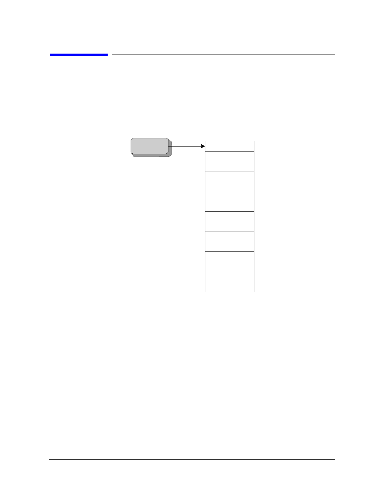
Setting up N9061A on the X-Series Analyzer
Setting up N9061A on the X-Series Analyzer
Figure 1-1 is an example mode menu map showing the N9061A (Remote Language Compatibility)
application selection on your signal analyzer. To select the N9061A application, press the
on the X-Series analyzer front panel and then select the
Remote Language Compatibility mode. If
there are more than six modes on the signal analyzer, then use the More button to find the Remote
Language Compatibility selection.
Figure 1-1 Example Mode Menu Map for X-Series Analyzers
Mode hardkey
27
Page 28
Getting Started
Mo d e Setup
Mode Setup
Logging
HP8560 series
HP8563E/EC
Restore Mode
Defa ul ts
HP8566/68
HP8566B
Cmd Error
On Off
Logging
Preferences
HP8561E/EC
HP8562E/EC
HP8560E/EC
HP8560 Series
HP8563E/EC
HP8564E/EC
HP8565E/EC
Preferences
HP8566B
HP8568A
HP8566A
HP8566/68
HP8568B
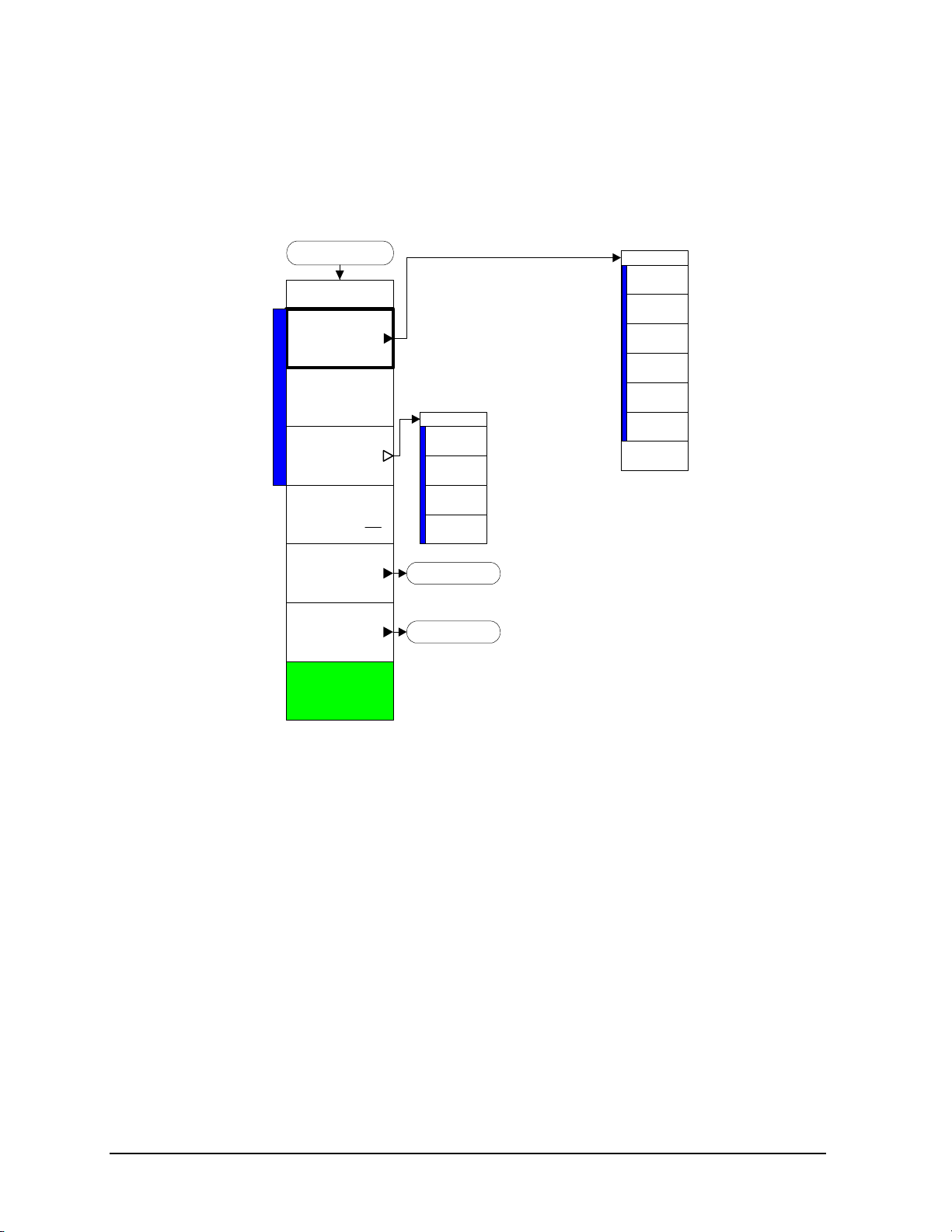
Setting up N9061A on the X-Series Analyzer
Then, to select the legacy analyzer you wish to emulate, press the Mode Setup hardkey on the front
panel. Figure 1-2 shows the menu map that allows you to select the 8560 series analyzer or 8566A/B,
8568A/B and therefore the remote control commands to be used in the X-Series analyzer.
Figure 1-2 Mode Setup > Legacy Instrument Selection Menu Map
The HP8560 series and HP8566A/B, 8568A/B key allow you to select which legacy instrument to
emulate. The selected instrument determines the response to the “ID?” command and affects the
behavior of commands such as IP. You can use any command offered by any of the legacy instruments
regardless of the language setting. However, if the command is not correct for the selected legacy
instrument there is no guarantee that the command will work as expected. This does not affect the
response to the SCPI command “*IDN?”.
28
Page 29

The legacy instrument selections are as follows:
Getting Started
Setting up N9061A on the X-Series Analyzer
8560E/EC Selects the
remote programming command ‘ID?’ to
preset and sets Span, Trace Points, couplings, VBW/RBW ratio, and Span/RBW ratio
appropriately as shown in Table 1-5.
8561E/EC Selects the
remote programming command ‘ID?’ to
preset and sets Span, Trace Points, couplings, VBW/RBW ratio, and Span/RBW ratio
appropriately as shown in Table 1-5.
8562E/EC Selects the
remote programming command ‘ID?’ to
preset and sets Span, Trace Points, couplings, VBW/RBW ratio, and Span/RBW ratio
appropriately as shown in Table 1-5.
8563E/EC Selects the
remote programming command ‘ID?’ to
preset and sets Span, Trace Points, couplings, VBW/RBW ratio, and Span/RBW ratio
appropriately as shown in Table 1-5. This is the default setting for the N9061A
application.
8564E/EC Selects the
remote programming command ‘ID?’ to
preset and sets Span, Trace Points, couplings, VBW/RBW ratio, and Span/RBW ratio
appropriately as shown in Table 1-5.
8560E/EC remote programming language and sets the response to the
HP8560E. It also performs an instrument
8561E/EC remote programming language and sets the response to the
HP8561E. It also performs an instrument
8562E/EC remote programming language and sets the response to the
HP8562E. It also performs an instrument
8563E/EC remote programming language and sets the response to the
HP8563E. It also performs an instrument
8564E/EC remote programming language and sets the response to the
HP8564E. It also performs an instrument
8565E/EC Selects the
remote programming command ‘ID?’ to
preset and sets Span, Trace Points, couplings, VBW/RBW ratio, and Span/RBW ratio
appropriately as shown in Table 1-5.
HP8566A Selects the
remote programming command ‘ID?’ to
preset and sets Span, Trace Points, couplings, VBW/RBW ratio, and Span/RBW ratio
appropriately as shown in Table 1-5 on page 30.
HP8566B Selects the
remote programming command ‘ID?’ to
preset and sets Span, Trace Points, couplings, VBW/RBW ratio, and Span/RBW ratio
appropriately as shown in Table 1-5 on page 30.
HP8568A Selects the
remote programming command ‘ID?’ to
preset and sets Span, Trace Points, couplings, VBW/RBW ratio, and Span/RBW ratio
appropriately as shown in Table 1-5 on page 30.
HP8568B Selects the
remote programming command ‘ID?’ to
preset and sets Span, Trace Points, couplings, VBW/RBW ratio, and Span/RBW ratio
appropriately as shown in Table 1-5 on page 30.
8565E/EC remote programming language and sets the response to the
HP8565E. It also performs an instrument
HP8566A remote programming language and sets the response to the
HP8566A. It also performs an instrument
HP8566B remote programming language and sets the response to the
HP8566B. It also performs an instrument
HP8568A remote programming language and sets the response to the
HP8568A. It also performs an instrument
HP8568B remote programming language and sets the response to the
HP8568B. It also performs an instrument
29
Page 30

Getting Started
Setting up N9061A on the X-Series Analyzer
NOTE Setting the remote language to anything other than ‘SCPI’ does not affect the
response to the SCPI command ‘*IDN?’ This command will still return the model
number and firmware version number of the X-Series signal analyzer.
Table 1-5 Span, Trace Points, Couplings, VBW/RBW Ratio, and Span/RBW Ratio
Settings
Remote
Language
8560E/EC 30 Hz 2.9 GHz 601 AC 1 91
8561E/EC 30 Hz 6.5 GHz 601 AC 1 91
8562E/EC 30 Hz 13.2 GHz 601 AC 1 91
8563E/EC 30 Hz 26.5 GHz 601 DC 1 91
8564E/EC 30 Hz 40 GHz 601 DC 1 91
8565E/EC 30 Hz 50 GHz 601 DC 1 91
HP8566A 2 GHz 22 GHz 1001 DC 3
HP8566B 2 GHz 22 GHz 1001 DC 3
Start Freq. Sto p
Freq.
Number of
Trace
Points
RF
Coupling
VBW/
RBW
Ratio
(VBW
one
step
wider
than
RBW)
(VBW
one
step
wider
than
RBW)
Span/RBW
Ratio
106
106
HP8568A 0 Hz 1.5 GHz 1001 DC 3
(VBW
one
step
wider
than
RBW)
30
106
Page 31

Getting Started
Setting up N9061A on the X-Series Analyzer
Table 1-5 Span, Trace Points, Couplings, VBW/RBW Ratio, and Span/RBW Ratio
Settings
Remote
Language
HP8568B 0 Hz 1.5 GHz 1001 DC 3
Start Freq. Stop
Freq.
Number of
Trace
Points
RF
Coupling
VBW/
RBW
Ratio
(VBW
one
step
wider
than
RBW)
Span/RBW
Ratio
106
31
Page 32

Getting Started
Setting up N9061A on the X-Series Analyzer
Cmd Error
Turning Cmd Error On or Off enables or disables the display of the "CMD ERR" error messages. The
default setting is On. The error message appears in the Message bar and also can be queried using
“ERR?”. The error message will occur if either the command syntax or any of its parameters are
incorrectly formed. The selected value is preserved after presetting or power cycling the instrument.
Disabling the display of command errors disables the display of all error types.
The format of the errors are as follows:
1.CMD ERR, <string>
This string will be limited to the first 20 characters of the input string (message unit).
Further details of these errors, after they have occurred, can be reviewed in the Cmd Error Log, as long
as Cmd Error Logging is enabled.
32
Page 33

Getting Started
Previous Page
Logging
Logging
Next Page
Clear Log
Refresh
Cmd Error Log
On Off
Setting up N9061A on the X-Series Analyzer
Logging
The N9061A application allows the logging of errors. These errors comprise details of command errors
and legacy commands that have been received but are not supported by the N9061A application. To
enable and view the error log select the
Logging softkey.
Figure 1-3 Logging Menu Map
Mode Setup hardkey from the front panel. Then select the
Previous Page/Next Page
When you are in the Logging menu, the main Signal Analysis display is obscured by the logging page.
The most recent log starts from the bottom of the window.
Previous Page and Next Page allow you to
scroll through the log file. To include commands sent to the analyzer since the log window display was
opened, press
Cmd Error Log
The
Cmd Error Log option allows you to turn the command error logging on or off. The default is Off.
Logging should not be used in a secure environment. When set to
log file, regardless of whether they have been displayed on the screen. When set to
command error messages are written to the log file. Switching
log file.
Refresh.
On, all error messages are stored in a
Off, no further
Cmd Error Log to Off does not clear the
The log file is also stored as a text file, called Logfile.txt, on the instrument. It is stored in the D:\
drive, in a folder called \User_My_Documents\[USERNAME]\My Documents\RLC\data.
The maximum size of the log is 10 MB. When the file reaches its maximum size, the first ten percent of
the file is automatically discarded, to clear space for subsequent error messages.
33
Page 34

Getting Started
Setting up N9061A on the X-Series Analyzer
Refresh
To update the log page with new entries, select
Refresh.
Clear Log
Clear Log softkey clears the error log.
The
The log can only be cleared by using the Clear Log function and cannot be cleared on power-up, remote
language switch or mode switch.
34
Page 35

Getting Started
Preferences
Preferences
RF Coupling
As Legacy
Allow SCPI
On Off
Atten Offset
On Off
Limit RBW/VBW
On Off
Always
DC Coupled
As Legacy
Always
AC Coupled
AC/DC Mode
SwpType Rule
Legacy
Best Dynamic
Range
Auto
Best Speed
Legacy
Swp Type Rules
Limit Swp Time
On Off
Setting up N9061A on the X-Series Analyzer
Preferences
The Preferences menu allows you to configure some analyzer settings when in remote language
compatibility mode. Figure 1-4 shows the Preferences menu map that is accessed by selecting the
Setup
hardkey on the front panel and then selecting the Preferences softkey. Preferences are not
affected by a power cycle, a remote language change, a mode switching or a mode preset. They are only
preset to their default state using
Restore Mode Defaults key in the Mode Setup menu (see Figure 1-2),
INST:DEF or SYST:PRES:PERS command.
Figure 1-4 Preferences Menu Map
Mode
Limit RBW/VBW
Setting
(VBW) values to those appropriate for the currently selected remote language. While this limitation
reduces measurement flexibility, it helps to ensure that the measurement time in emulation mode is the
Limit RBW/VBW to On limits the valid resolution bandwidth (RBW) and video bandwidth
same as the legacy measurement time, and ensures that the responses to RB? and VB? match the legacy
instrument. The default state is
Off. Setting this key to Off causes the RBW and VBW filters to use the
X-Series analyzer range of values for all remote languages.
Atten Offset
Setting
increasing the noise floor. Since many of the older sp ectrum analyzers had noise floor 10 dB higher than
Atten Offset to On allows larger input power to be applied to the analyzer, while significantly
the X-Series analyzer, this gives the most accurate emulation. The default state is
Off.
35
Page 36

Getting Started
Setting up N9061A on the X-Series Analyzer
Sweep Type Rules
Sweep Type Rules changes the Auto rules for determining whether the instrument uses FFT or Swept
mode (this can be manually overridden). FFT mode offers substantially faster measurements in some
cases. The HP8566A/B, 8568A/B series did not have FFT mode capability, so most accurate emulation
requires that the instrument preserves Swept mode unless you manually overrides that setting. The
8560-series analyzers use both FFT and Swept mode, in which case “Legacy” is equivalent to “Dynamic
range”.
RF Coupling
RF Coupling allows you to override the legacy instrument behavior for AC and DC coupling. This
command is required because legacy instruments had AC cutoff frequencies of 100 kHz and the X-series
analyzers have an AC cutoff frequency of 10 MHz.
As Legacy sets coupling to AC or DC whenever the legacy instrument would be set to AC or DC
coupled mode via power on, preset, or an explicit command. Due to changes in the coupling cutoff
frequency, measurement performance below 10 MHz while in AC-coupled mode may not match the
legacy analyzer performance.
Always AC sets AC coupling while in Language Compatibility Mode, overriding other instrument
settings including power on, preset, or an explicit command. This setting maximizes instrument
robustness, and is recommended for instruments that are not used to measure signals below 10 MHz.
Always DC sets DC coupling while in Language Compatibility Mode, overriding other instrument
settings including power on, preset, or explicit command. This will maximize instrument sensitivity to
signals below 10 MHz, and may be required for measurements between 100 KHz and 10 MHz. When in
this mode, extra care should be taken to ensure that DC voltage levels are within the allowable range for
the X-Series analzysers.
Limit Sweep Time
Allows you to constrain the sweep time to no less than the minimum sweep time of the legacy
instruments. If set to On, the sweep time will be constrained to no less than the value listed below. If set
to Off, no constraint is applied.
Table 1-6 Minimum Sweep Time for the Legacy Instruments
Instrument Sweep Time
(None Zero Span)
HP8566A/B, HP8568A/B 20 ms 1 us
HP8560 series 50 ms 50 us
Sweep Time
(Zero Span)
36
Page 37

Getting Started
Setting up N9061A on the X-Series Analyzer
Restore Mode Defaults
Resets the state for the currently active mode by resetting the mode persistent setting to their default
values and by performing a mode preset. This function will never cause a mode switch. This function
performs a full preset on the active mode.
Send Commands
After you finish setting up the N9061A application, you can send the commands of the legacy products
(8560 Series, 8566A/B, or 8568A/B) to X-Series analyzers. It is recomanded to use Agilent 82357B
USB/GPIB interface and free instrument to PC connection tool Agilent IO Libraries Suite when you
connct the instrument to a PC. For more details, visit:
http://www.agilent.com/find/82357B
http://www.agilent.com/find/iolib
NOTE The commands can ONLY be sent via a GPIB connection. It will not work for a
LAN connecttion.
37
Page 38

Getting Started
Running Software that Requires SCPI Commands
Running Software that Requires SCPI Commands
When a legacy remote language has been selected, you only have access to a very small subset of SCPI
commands. If you are not familiar with the SCPI remote programming language, Chapter 5 , “A Brief
Introduction to the SCPI Language,” on page 355 contains some useful information.
The SCPI commands available while using other remote languages are:
Table 1-7 SCPI Commands
SCPI Commands Description
*IDN? Queries and returns the instrument identification
string.
*RST Performs an instrument preset.
INSTrument:DEFault Restores mode defaults.
INSTrument:SELect
INSTrument:SELect?
INSTrument:NSELect
INSTrument:NSELect?
[:SENSe]:SWEep:TYPE AUTO|SWEep|FFT
[:SENSe]:SWEep:TYPE?
:SYST em:OPTions? Returns a list of installed options.
INPut:COUPling AC|DC|RLC
INPut:COUPling?
:SYST em:LANGuage HP8560E | HP8561E | HP8562E |
HP8563E | HP8564E | HP8565E | HP8566A | HP8566B |
HP8568A | HP8568B
:SYSTem:LANGuage?
:SYST em:COMMunicate:RLBC:SCPI:ENABle ON|OFF T oggles whether SCPI available in RLBC mode
Selects an application by mode name. (Use RLC
to select the N9061A application)
Selects an application by mode number. (Use 266
to select the N9061A application)
Sets the Sweep Type.
Defaults to AUTO.
Sets the input coupling.
Defaults to RLC.
Sets the current remote language.
or not.
2
1
.
1
.
2
:SYST em:COMMunicate:RLBC:SCPI:ENABle ON|OFF T oggles whether SCPI available in RLBC mode
or not.
[:SENSe]:RLC:SWEep:TYPE:AUTO:RULes
AUTO|SPEed|DRANge|LEGACY
[:SENSe]:RLC:SWEep:TYPE:AUTO:RULes?
38
Sets the auto rule setting for Sweep Type.
2
Page 39

Running Software that Requires SCPI Commands
Table 1-7 SCPI Commands
SCPI Commands Description
Getting Started
[:SENSe]:RLC:BANDwidth:LIMit ON|OFF|1|0
[:SENSe]:RLC:BANDwidth:LIMit?
[:SENSe]:RLC:ATTenuation:STATe ON|OFF|1|0
[:SENSe]:RLC:ATTenuation:STATe?
Toggles legacy bandwidth limiting on and off.
T oggles internal attenuation on and off.
to OFF.
1. After changing into or out of RLC mode, allow a 1s delay before sending subsequent commands.
2. This command is only available if the N9061A application is installed on your analyzer.
2
Defaults
2
39
Page 40

Getting Started
Service and Calibration
Service and Calibration
Since the Performance Verification and Adjustment Software uses the SCPI command languag e, you
need to exit the N9061A (RLC) application and change to the Spectrum Analyzer application prior to
calibration or service of your Agilent signal analyzer.
40
Page 41

2 Legacy Analyzer Command List
41
Page 42

Legacy Analyzer Command List
Table of All Legacy Analyzer Commands
Table of All Legacy Analyzer Commands
The following table lists all of the original programming commands from the legacy analyzers (that is,
the 8566A/B, the 8568A/B, and the 8560 Series), and indicates which are supported in N9061A. Refer to
the alphabetical listing of commands in Chapter 4 , “Programming Commands,” on page 75 for more
detailed information about each supported command.
Table 2-1 Alphanumeric List of all Legacy Commands Showing their N9061A Support
Command Description 8566 8568 8560
Series
A1 Clear-writes trace A Yes Yes Yes Page 79
A2 Max Holds trace A Yes Yes Yes Page 80
A3 View trace A Yes Yes Yes Page 81
A4 Blanks trace A Yes Yes Yes Page 82
ABORT Interrupt operation of all
user-defined functions
ABS Absolute No No No
ACP Performs the adjacent channel
power measurement
ACPACCL Accelerate adjacent channel
power measurement
ACPALPHA Adjacent channel power alpha
weighting
ACPALTCH Adjacent channel power
alternate channels
N/A N/A No
N/A N/A N/A
N/A N/A No
N/A N/A Yes Page 83
N/A N/A Yes Page 84
Page for
Further
Details
ACPBRPER Adjacent channel power burst
period
ACPBRWID Adjacent channel power burst
width
ACPBW Specifies channel bandwidth for
ACP measurement
ACPCOMPUTE Compute adjacent channel
power
ACPCONTM Performs ACP measurement in
continuous sweep
ACPE Adjacent channel power
extended
42
N/A N/A Yes Page 85
N/A N/A Yes Page 86
N/A N/A Yes Page 87
N/A N/A Yes Page 88
N/A N/A N/A
N/A N/A N/A
Page 43

Legacy Analyzer Command List
Table of All Legacy Analyzer Commands
Table 2-1 Alphanumeric List of all Legacy Commands Showing their N9061A Support
Command Description 8566 8568 8560
Series
ACPERR ACP measurement error query N/A N/A N/A
ACPFRQWT Adjacent channel power
frequency weighting
ACPGR Adjacent channel power graph
on or off
ACPGRAPH Compute adjacent channel
power graph
ACPLOWER Lower adjacent channel power N/A N/A Yes Page 90
ACPMAX Maximum adjacent channel
power
ACPMEAS Measure adjacent channel
power
ACPMETHOD Adjacent channel power
measurement method
ACPMK Adjacent channel power marker
on or off
N/A N/A Yes Page 89
N/A N/A N/A
N/A N/A No
N/A N/A Yes Page 91
N/A N/A Yes Page 92
N/A N/A No
N/A N/A N/A
Page for
Further
Details
ACPMSTATE Adjacent channel power
measurement state
ACPPAR ACP manual or auto N/A N/A N/A
ACPPWRTX Total power transmitted N/A N/A Yes Page 94
ACPRSLTS Adjacent channel power
measurement results
ACPSNGLM Performs ACP measurement in
single sweep
ACPSP Channel spacing N/A N/A Yes Page 96
ACPT Adjacent channel power
T weighting
ACPUPPER Upper adjacent channel power N/A N/A Yes Page 98
ACTDEF Give user-defined function
active status
ACTVF Active function N/A N/A N/A
ACTVFUNC Creates a user defined active
function
N/A N/A Yes Page 93
N/A N/A Yes Page 95
N/A N/A N/A
N/A N/A Yes Page 97
N/A N/A N/A
N/A N/A No
43
Page 44

Legacy Analyzer Command List
Table of All Legacy Analyzer Commands
Table 2-1 Alphanumeric List of all Legacy Commands Showing their N9061A Support
Command Description 8566 8568 8560
Series
ADD Add No No No
ADJALL LO & IF adjustment N/A N/A Yes Page 99
ADJCRT Adjust CRT alignmen t N/A N/A No
ADJIF Adjust IF N/A N/A No
AMB Trace A − trace B -> trace A Yes Yes Yes Page 100
AMBPL Trace A − trace B + Display
Line -> trace A
AMPCOR Applies amplitude correction at
specified frequencies
AMPCORDATA Amplitude correction data N/A N/A No
AMPCORSAVE Save amplitude correction data N/A N/A No
AMPCORSIZE Amplitude correction data array
size
AMPCORRCL Amplitude correction recall N/A N/A No
Yes Yes Yes Page 101
N/A N/A No
N/A N/A No
Page for
Further
Details
AMPLEN Amplitude correction length N/A N/A N/A
ANLGPLUS Turns on or off the Analog+
display mode
ANNOT Disp lay Annotation Yes Yes Yes Page 102
APB Trace A + trace B -> trace A Yes Yes Yes Page 103
ARRAYDEF Defines an array N/A N/A No
AT Input Attenuation Yes Yes Yes Page 104
AUNITS Amplitude Units Yes Yes Yes Page 106
AUTO Auto couple N/A N/A N/A
AUTOCPL Auto couple N/A N/A Yes Page 108
AUTOEXEC Turns on or off the function
defined with AUTOFUNC
AUTOFUNC Defines a function for automatic
execution
AUTOSAVE Automatically saves trace N/A N/A No
AVG Average No No No
N/A N/A N/A
N/A N/A No
N/A N/A No
AXB Exchange Traces A & B Yes Yes Yes Page 109
44
Page 45

Legacy Analyzer Command List
Table of All Legacy Analyzer Commands
Table 2-1 Alphanumeric List of all Legacy Commands Showing their N9061A Support
Command Description 8566 8568 8560
Series
B1 Clear-writes trace B Yes Yes Yes Page 110
B2 Max Holds trace B Yes Yes Yes Page 111
B3 View trace B Yes Yes Yes Page 112
B4 Blanks trace B Yes Yes Yes Page 113
BAUDRATE Baud rate of spectrum analyzer N/A N/A N/A
BIT Return or receive state of bit N/A N/A N/A
BITF Bit flag N/A N/A N/A
BL Trace B − Display line -> trace BYes Yes N/A Page 1 14
BLANK Blanks specified trace Yes Yes Yes Page 115
BML Trace B − Display line -> trace BYes Yes Yes Page 1 16
BRD Bus Read No No N/A
BTC Transfer trace B to C Yes Yes N/A Page 117
Page for
Further
Details
BWR Bus Write NoNoN/A
BXC Exchange Traces B & C Yes Yes N/A Page 118
C1 Turns off A - B Yes Yes Yes Page 119
C2 A − B -> A Yes Yes Yes Page 120
CA Couples Attenuation Yes Yes Yes Page 121
CAL Calibrate N/A N/A N/A
CARDLOAD Copies data from memory card
to module memory
CARDSTORE Copies data to memory card N/A N/A No
CARROFF Carrier off power N/A N/A No
CARRON Carrier on power N/A N/A Yes Page 123
CAT Catalog N/A N/A N/A
CATALOG Catalog N/A N/A No
CF Center Frequency Yes Yes Yes Page 124
CHANNEL Channel selection N/A N/A Yes Page 126
N/A N/A No
45
Page 46

Legacy Analyzer Command List
Table of All Legacy Analyzer Commands
Table 2-1 Alphanumeric List of all Legacy Commands Showing their N9061A Support
Command Description 8566 8568 8560
Series
CHANPWR Channel power N/A N/A Yes Page 127
CHP Performs the channel power
measurement
CHPGR Channel power graph on or off N/A N/A N/A
CHPWRBW Channel power bandwidth N/A N/A Yes Page 128
CLRAVG Reset avg. counter to 1 Yes Yes N/A Page 129
CLRBOX Clears a rectangular area on the
analyzer display
CLRDSP Clear display N/A N/A No
CLRSCHED Clears autosave & autoexec
schedule buffer
CLRW Clear-writes specified trace Yes Yes Yes Page 130
CLS Clear status byte N/A N/A N/A
CMDERRQ Command error query N/A N/A N/A
N/A N/A N/A
N/A N/A N/A
N/A N/A No
Page for
Further
Details
CNF Confidence test N/A N/A N/A
CNTLA Auxiliary interface control line AN/A N/A No
CNTLB Auxiliary interface control line BN/A N/A No
CNTLC Auxiliary interface control line CN/A N/A No
CNTLD Auxiliary interface control line DN/A N/A No
CNTLI Auxiliary interface control line
input
CNVLOSS Selects ref level offset to
calibrate amplitude display
COMB Turns the comb generator on or
off
COMPRESS Compress No No N/A
CONCAT Concat No No N/A
CONTS Contin uous sweep mode Yes Yes Yes Page 132
N/A N/A No
No N/A No
N/A N/A N/A
46
Page 47

Legacy Analyzer Command List
Table of All Legacy Analyzer Commands
Table 2-1 Alphanumeric List of all Legacy Commands Showing their N9061A Support
Command Description 8566 8568 8560
Series
CORREK Correction factors on N/A N/A N/A
COUPLE Selects AC or DC coupling N/A N/A Yes Page 133
CR Couples Resolution BW Yes Yes Yes Page 134
CRTHPOS Horizontal position of CRT
display
CRTVPOS Vertical position of CRT
display
CS Couples Step Size Yes Yes Ye s Page 135
CT Couples Sweep Time Yes Yes Yes Page 136
CTA Converts display units to dBm No No N/A
CTM Converts dBm to display units No No N/A
CTRLHPIB Allows SA to control HP-IB N/A N/A No
CV Couples Vide o Bandwidth Yes Yes Yes Page 137
D1 Sets display to normal size No No N/A
N/A N/A N/A
N/A N/A N/A
Page for
Further
Details
D2 Sets display to full CRT size No No N/A
D3 Sets display to expanded size No No N/A
DA Display Memory Address Yes Yes N/A Page 138
DATEMODE Set the date display format N/A N/A No
DD Display write binary No No N /A
DELMKBW Occupied power bandwidth
within delta marker
DEMOD Turns the demodulator on or off N/A N/A No
DEMODAGC Demodulation automatic gain
control
DEMODT Demodu lati on time N/A N/A No
DET Detection Mode Yes Yes Yes Page 140
DISPOSE Frees Memory No No No
DIV Divide NoNoNo
DL Display Line Level Yes Yes Yes Page 141
DLE Turns the display line on/off Yes Yes N/A Page 143
N/A N/A Yes Page 139
N/A N/A No
47
Page 48

Legacy Analyzer Command List
Table of All Legacy Analyzer Commands
Table 2-1 Alphanumeric List of all Legacy Commands Showing their N9061A Support
Command Description 8566 8568 8560
Series
DLYSWP Delay sweep N/A N/A Yes Page 144
DN Reduces the active function by
applicable step size
DONE Synchronizing function Yes Yes Yes Page 145
DOTDENS Sets the dot density value in
Analog+ display mode
DR Display Memory Address Read Yes Yes N/A Page 146
DRAWBOX Draws a rectangular box on
analyzer display
DSPLY Display No No No
DT Define Terminator No No N/A
DW Display Memory Address Write No No N/A
E1 Active marker to maximum
signal
N/A N/A N/A
N/A N/A N/A
N/A N/A N/A
Yes Yes Yes Page 147
Page for
Further
Details
E2 Active marker to center
frequency
E3 Active marker frequency to CF
step size
E4 Active marker to reference level Yes Yes Yes Page 150
EDITDONE Indicates limit line editing is
complete
EDITLIML Allows current limit line to be
edited
EE Enable entry No No N/A
EK Enable knob No No N/A
ELSE Conditional Programming
(If…then…else…endif)
EM Erase trace C memory No No No
ENDIF Conditional Programming
(If…then…else…endif)
ENTER Enter from HP-IB No No No
Yes Yes Yes Page 148
Yes Yes Yes Page 149
N/A N/A Yes Page 151
N/A N/A No
No No No
No No N/A
EP Enter parameter function N/A N/A N/A
48
Page 49

Legacy Analyzer Command List
Table of All Legacy Analyzer Commands
Table 2-1 Alphanumeric List of all Legacy Commands Showing their N9061A Support
Command Description 8566 8568 8560
Series
ERASE User memory & registers erased No No N/A
ERR Queries the error queue Yes Yes Yes Page 152
ET Elapsed time N/A N/A Yes Page 154
EX Exchanges trace A & B Yes Yes Yes Page 155
EXP Exponential No No No
EXTMXR Presets external mixing mode No N/A No
FA Start frequency Yes Yes Yes Page 156
FB Stop frequency Yes Yes Yes Page 157
FDIAG Frequency diagnostics N/A N/A No
FDSP Frequency display off N/A N/A Yes Page 158
FFT Fast fourier transform No No No
FFTAUTO Marker to Auto FFT N/A N/A N/A
FFTCLIP FFT signal clipped N/A N/A N/A
Page for
Further
Details
FFTCONTS FFT continuous sweep N/A N/A N/A
FFTKNL Fast fourier transform kernel No No N/A
FFTMKR FFT markers N/A N/A N/A
FFTMM FFT marker to midscreen N/A N/A N/A
FFTMS FFT marker to FFT stop
frequency
FFTOFF FFT off N/A N/A N/A
FFTPCTAM FFT percent amplitude
modulation
FFTPCTAMR FFT percent amplitude
modulation readout
FFTSNGLS FFT single sweep N/A N/A N/A
FFTSTAT FFT status N/A N/A N/A
FFTSTOP FFT stop frequen c y N/A N/A N/A
FMGAIN FM gain N/A N/A N/A
FOFFSET Frequency offset Yes Yes Yes Page 159
N/A N/A N/A
N/A N/A N/A
N/A N/A N/A
49
Page 50

Legacy Analyzer Command List
Table of All Legacy Analyzer Commands
Table 2-1 Alphanumeric List of all Legacy Commands Showing their N9061A Support
Command Description 8566 8568 8560
Series
FORMAT Erase & format the selected
memory device
FPKA Fast preselector peak Yes N/A N/A Page 161
FREF Frequency reference N/A N/A Yes Page 162
FS Full frequency span Yes Yes Yes Page 163
FULBAND Set start/stop freq for ext mixing
bands
FUNCDEF Function definition No No No
GATE Turn time-gating on or off N/A N/A Yes Page 166
GATECTL Gate control N/A N/A Yes Page 167
GC Gate preset N/A N/A N/A
GD Gate delay N/A N/A Yes Page 168
GDRVCLPAR Clear pulse parameters N/A N/A N/A
GDRVGDEL Gate Delay for the frequency
window
N/A N/A No
No N/A No
N/A N/A N/A
Page for
Further
Details
GDRVGLEN Gate length for frequency &
time windows
GDR VG T Turns gate in frequency window
on or off
GDRVGTIM Gate trigger to marker position
for time window
GDRVPRI Pulse repetition interval N/A N/A N/A
GDRVPWID Pulse width N/A N/A N/A
GDRVRBW Couple resolution bandwidth to
pulse width
GDRVREFE Enter reference edge N/A N/A N/A
GDRVST Couple sweep time to pulse
repetition interval
GDRVSWAP Update the time or frequency
window
GDRVSWDE Delay sweep for time window N/A N/A N/A
N/A N/A N/A
N/A N/A N/A
N/A N/A N/A
N/A N/A N/A
N/A N/A N/A
N/A N/A N/A
50
Page 51

Legacy Analyzer Command List
Table of All Legacy Analyzer Commands
Table 2-1 Alphanumeric List of all Legacy Commands Showing their N9061A Support
Command Description 8566 8568 8560
Series
GDRVSWP Sweep time for the time
window
GDRVUTIL Turns the gate utility on or off N/A N/A N/A
GDRVVBW Couple video bandwidth to the
gate length
GETPLOT Get plot N/A N/A N/A
GETPRNT Get print N/A N/A N/A
GL Gate length N/A N/A Yes Page 169
GP Sets the polarity
(positive/negative) of the gate
trigger
GR Plot GPIB input as Graphs No No N/A
GRAT Graticule on/off Yes Yes Yes Page 171
HAVE Checks for options installed N/A N/A N/A
N/A N/A N/A
N/A N/A N/A
N/A N/A Yes Page 170
Page for
Further
Details
HD Holds data entry No No No Page 172
HN Harmonic number N /A N/A N/A
HNLOCK Harmonic lock No N/A No
HNUNLK Harmonic band unlock No N/A No
I1 Sets the RF coupling to AC N/A Yes N/A Page 173
I2 Sets the RF coupling to DC N/A Yes N/A Page 175
IB Input to trace B memory No No N/A
ID Instrument identification Yes Yes Yes Page 177
IDCF Identified signal to center
frequency
IDFREQ Identified signal frequency N/A N/A No
IDSTAT Signal identifier status No N/A N/A
IF Conditional Programming
(If…then…else…endif)
IFTKNL 16 bit discrete fourier transform No No N/A
INT Integer No No No
N/A N/A No
No No No
INZ Input impedance N/A N/A N/A
51
Page 52

Legacy Analyzer Command List
Table of All Legacy Analyzer Commands
Table 2-1 Alphanumeric List of all Legacy Commands Showing their N9061A Support
Command Description 8566 8568 8560
Series
IP Instrument preset Yes Yes Yes Page 178
KEYCLR Clear user defined keys N/A N/A No
KEYCMD Define function & label of
softkey
KEYDEF Assign function to soft key No No No
KEYENH Key enhance N/A N/A N/A
KEYEXC Executes specified soft key No No N/A
KEYLBL Relabels softkey without
changing its function
KS, Mixer level Yes Yes N/A Page 179
KS= HP8566: Selects factory
preselector setting
HP8568: Marker counter
frequency resolution
KS( Locks the save registers Yes Yes N/A Page 181
N/A N/A N/A
N/A N/A N/A
Yes
Yes
No
Page for
Further
Details
Page 180
KS) Unlocks the save registers Yes Yes N/A Page 182
KS> Specifies preamp gain for signal
input 2
KS< Specifies preamp gain for signal
input 1
KS| Display memory address write No No N/A
KS# Turns off YTX self-heating
correction
KS/ Allows preselector to be peaked
manually
KS123 Returns up to 1001 words
display memory
KS125 Writes up to 1001 display
memory words
KS126 Retu rns every Nth value of a
trace
KS127 Sets analyzer to accept binary
display write
N/A No N/A
N/A No N/A
No N/A N/A
No N/A N/A
No No N/A
No No N/A
No No N/A
No No N/A
52
Page 53

Legacy Analyzer Command List
Table of All Legacy Analyzer Commands
Table 2-1 Alphanumeric List of all Legacy Commands Showing their N9061A Support
Command Description 8566 8568 8560
Series
KS39 Writes display memory address
in fast binary
KS43 Sets SRQ 102 when frequency
limit exceeded
KS91 Returns the amplitude error No No N/A
KS92 Specifies value DL, TH, active
mkr in display units
KS94 Returns code for harmonic
number in binary
KSA Sets amplitude units to dBm Yes Yes N/A Page 183
KSa Selects normal detection Yes Yes N/A Page 184
KSB Sets amplitude units to dBmV Yes Yes N/A Page 185
KSb Selects positive peak detection Yes Yes N/A Page 186
KSC Sets amplitude units to dBuV Yes Yes N/A Page 187
No No N/A
No No N/A
No No N/A
No No N/A
Page for
Further
Details
KSc Trace A + trace B -> trace A Yes Yes N/A Page 188
KSD Sets amplitude units to V Yes Yes N/A Page 189
KSd Selects negative peak detection Yes Yes N/A Page 190
KSE Sets the analyzer title mode Yes Yes N/A Page 191
KSe Selects sample detection Yes Yes N/A Page 192
KSF HP8566: Shifts the YTO
HP8568: Measures the Sweep
Time
KSf Recover last instrument state at
power on
KSG Turns on video averaging Yes Yes N/A Page 193
KSg Turns off the display Yes Yes N/A Page 194
KSH Turns off video averaging Yes Yes N/A Page 19 5
KSh Turns on the display Yes Yes N/A Page 196
KSI Allows the reference level to be
extended
KSi Exchanges traces B & C Yes Yes N/A Page 197
No No N/A
No No N/A
No No N/A
53
Page 54

Legacy Analyzer Command List
Table of All Legacy Analyzer Commands
Table 2-1 Alphanumeric List of all Legacy Commands Showing their N9061A Support
Command Description 8566 8568 8560
Series
KSJ Manu al control of DACs No No N/A
KSj Views trace C Yes Yes N/A Page 198
KSK HP8566: Active Mkr to next
highest peak
HP8568: Counts pilot IF at
marker
KSk Blanks trace C Yes Yes N/A Page 200
KSL Turns off marker noise function Yes Yes N/A Page 201
KSl Moves trace B into trace C Yes Yes N/A Page 202
KSM Turns on marker noise function Yes Yes N/A Page 203
KSm Turns off the graticule Yes Yes N/A Page 204
KSN Marker minimum value
detected
KSn Turns on the graticule Yes Yes N/A Page 206
Yes No N/A Page 199
Yes No N/A Page 205
Page for
Further
Details
KSO Marker span Yes Yes N/A Page 207
KSo Turns off the annotation Yes Yes N/A Page 208
KSP GPIB address No No N/A
KSp Turns on the annotation Yes Yes N/A Page 209
KSQ Unlocks frequency band No No N/A
KSq Decouples IF gain and input
attenuation
KSR Turns on service diagnostics No No N/A
KSr Sets service request 102 No No N/A
KSS HP8566: Fast GPIB operation
HP8568: Determine second LO
frequency
KST HP8566: Fast preset
HP8568: Shifts second LO
down
KSt HP8566: Locks frequency band
HP8568: Continues sweep from
marker
No No N/A
No No N/A
Yes No N/A Page 210
No No N/A
54
Page 55

Legacy Analyzer Command List
Table of All Legacy Analyzer Commands
Table 2-1 Alphanumeric List of all Legacy Commands Showing their N9061A Support
Command Description 8566 8568 8560
Series
KSU HP8566: External mixer preset
HP8568: Shift second LO up
KSu Stops the sweep at the active
marker
KSV Frequency offset Yes Yes N/A Page 211
KSv HP8566: External mixer
frequency identifier
HP8568: Inhibits phase lock
KSW Amplitude error correction
routine
KSw Displays amplitude error
correction routine
KSX Amplitude correction factors on No No N/A
KSx Sets trigger mode to external Yes Yes N/A Page 212
KSY Amplitude correction factors off No No N/A
No No N/A
No No N/A
No No N/A
No No N/A
No No N/A
Page for
Further
Details
KSy Sets trigger mode to video Yes Yes N/A Page 213
KSZ Reference level offset Yes Yes N/A Page 214
KSz Sets the display storage address No No N/A
L0 Turns off the display line Yes Yes Yes Page 215
LB Writes text label No No No
LCLVAR Defines a local variable for use N/A N/A No
LF Preset 0−2.5GHz Yes N/A N/A Page 216
LG Selects log scale Yes Yes Yes Page 217
LIMD Delta amplitude value for limit
line segment
LIMF Frequency value for limit-line
segment
LIMIDEL Erase contents of limit line table N/A N/A N/A
LIMIDISP Controls when the limit line(s)
are displayed
LIMIFAIL Limit line fail N/A N/A Yes Page 220
N/A N/A Yes
N/A N/A Yes Page 219
N/A N/A N/A
55
Page 56

Legacy Analyzer Command List
Table of All Legacy Analyzer Commands
Table 2-1 Alphanumeric List of all Legacy Commands Showing their N9061A Support
Command Description 8566 8568 8560
Series
LIMIFT Select frequency or time limit
line
LIMIHI Upper limit N /A N/A N/A
LIMILINE Limit line N/A N/A N/A
LIMILO Lower limit N/A N/A N/A
LIMIMIRROR Mirror limit line N/A N /A N/A
LIMIMODE Limit line entry mode N/A N/A N/A
LIMIPURGE Disp oses of current limit line,
not limit line table
LIMIRCL Load stored limit line into limit
line table
LIMIREL Determine whether li mi t line
values absolute/relative
LIMISAV Save contents of limit line table
for recall
N/A N/A N/A
N/A N/A Yes Page 221
N/A N/A No
N/A N/A Yes Page 222
N/A N/A No
Page for
Further
Details
LIMISEG Define slope & offset of limit
line segments
LIMISEGT Enter limit line segment for
sweep time
LIMITEST Compare active trace data to
limit line parameters
LIML Amplitude value for limit line
segment in lower limit line
LIMM Middle amplitude valu e for
limit-line segment
LIMTFL Specifies a flat limit-line
segment
LIMTSL Specifies a sloped limit-line
segment
LIMU Amplitude value for limit line
segment in upper limit line
LINFILL Line fill N/A N/A N/A
LL Provides lower left recorder
output voltage at rear
N/A N/A N/A
N/A N/A N/A
N/A N/A Yes
N/A N/A Yes Page 223
N/A N/A Yes
N/A N/A No
N/A N/A Yes Page 224
N/A N/A Yes Page 225
No No N/A
56
Page 57

Legacy Analyzer Command List
Table of All Legacy Analyzer Commands
Table 2-1 Alphanumeric List of all Legacy Commands Showing their N9061A Support
Command Description 8566 8568 8560
Series
LN Selects linear scale Yes Yes Yes Page 226
LOAD Load article/file into internal
memory
LOG Log No No No
LOLIMOFF LO Limit Off No No N/A
LSPAN Last span N/A N/A N/A
M1 Turns off all markers Yes Yes Yes Page 227
M2 Marker Normal Yes Yes Yes Page 228
M3 Marker Delta Yes Yes Yes Page 229
M4 Marker zoom Yes Yes N/A Page 230
MA Returns the amplitude of active
marker
MBIAS Mixer bias N/A N/A No
MBRD Processor memory block read No No N/A
N/A N/A N/A
Yes Yes Yes Page 231
Page for
Further
Details
MBWR Processor memory block write No No N/A
MC0 Turns off the marker frequency
counter
MC1 Turns on the marker frequency
counter
MDS Measurement data size Yes Yes N/A Page 234
MDU Measurement data units No No N/A
MEAN Returns mean value of trace in
display units
MEANPWR Mean power measurement N/A N/A Yes Page 236
MEANTH Trace mean above threshold N/A N/A N/A
MEAS Measurement status N/A N/A No
MEASOFF Measurement off N/A N/A N/A
MEASURE Measure mode N/A N/A N/A
MEM Returns amount of memory
available
MENU Menu N/A N/A No
N/A Yes N/A Page 232
N/A Yes N/A Page 233
Yes Yes Yes Page 235
No No No
57
Page 58

Legacy Analyzer Command List
Table of All Legacy Analyzer Commands
Table 2-1 Alphanumeric List of all Legacy Commands Showing their N9061A Support
Command Description 8566 8568 8560
Series
MERGE Merge two traces No No N/A
MF Returns frequency of the active
marker
MIN Minimum No No No
MINH Min Hold N/A N/A Yes Page 239
MINPOS Returns the minimum position
in the trace
MIRROR Mirror image of the trace No No N/A
MKA Amplitude of the active marker Yes Yes Yes Page 241
MKACT Specifies the active marker Yes Yes N/A Page 242
MKACTV Marker as the active function N/A N/A N/A
MKBW Marker bandwidth N/A N/A Yes Page 243
MKCF Moves the active marker to
center frequency
Yes Yes Yes Page 238
Yes Yes N/A Page 240
Yes Yes Yes Page 244
Page for
Further
Details
MKCHEDGE Marker to channel edge N/A N/A No
MKCONT Continues sweeping from the
marker after stop
MKD Delta marker Yes Yes Yes Page 245
MKDELCHBW Delta markers to channel power
bandwidth
MKDLMODE Marker delta display line mode N/A N/A N/A
MKDR Reciprocal of marker delta N/A N/A No
MKF Specifies the frequency of the
active marker
MKFC Turns the marker frequency
counter on or off
MKFCR Specifies the marker frequency
counter resolution
MKMCF Marker mean to center
frequency
MKMIN Moves active marker to
minimum signal detected
No No N/A
N/A N/A No
Yes Yes Yes Page 246
N/A Yes Yes Page 247
N/A Yes Yes Page 248
N/A N/A No
Yes Yes Yes Page 250
58
Page 59

Legacy Analyzer Command List
Table of All Legacy Analyzer Commands
Table 2-1 Alphanumeric List of all Legacy Commands Showing their N9061A Support
Command Description 8566 8568 8560
Series
MKN Normal marker Yes Yes Yes Page 251
MKNOISE Marker noise function Yes Yes Yes Page 252
MKOFF Turns all markers or the active
marker off
MKP Specifies the horizontal position
of the marker
MKPAUSE P auses the sweep at the active
marker
MKPK Marker peak Yes Yes Yes Page 255
MKPT Marker peak threshold N/A N/A Yes Page 256
MKPX Marker peak excursion Yes Yes Yes Page 257
MKREAD Specifies marker readout mode Yes Yes N/A Page 258
MKRL Moves the active marker to
reference level
Yes Yes Yes Page 253
Yes Yes N/A Page 254
No No N/A
Yes Yes Yes Page 260
Page for
Further
Details
MKSP Marker span Yes Yes Yes Page 261
MKSS Marker step size Yes Yes Yes Page 262
MKSTOP Stops the sweep at the active
marker
MKT Position marker in unit s of time N/A N/A Yes Page 263
MKTBL Marker table N/A N/A N/A
MKTRACE Marker trace Yes Yes N/A Page 264
MKTRACK Turns the marker signal track on
or off
MKTYPE Specifies the type of active
marker to be used
ML Mixer Level Yes Yes Yes Page 267
MOD Modulo No No No
MODE Mode of operation N/A N/A N/A
MODRCLT Recalls trace from module
memory
MODSAVT Saves trace in module memory N/A N/A No
No No N/A
Yes Yes Yes Page 265
Yes Yes N/A Page 266
N/A N/A No
59
Page 60

Legacy Analyzer Command List
Table of All Legacy Analyzer Commands
Table 2-1 Alphanumeric List of all Legacy Commands Showing their N9061A Support
Command Description 8566 8568 8560
Series
MOV Move NoNoNo
MPY Multiply No No No
MRD Memory Read No No N/A
MRDB Memory read byte No No N/A
MSDEV Specifies mass storage device N/A N/A No
MSI Mass storage interface N/A N/A N/A
MT0 Turns off marker signal track Yes Yes Yes Page 269
MT1 Turns on marker signal track Yes Yes Yes Page 270
MWR Memory Write NoNoN/A
MWRB Memory write byte No No N/A
MXM Maximum No No No
MXMH Max Hold Yes Yes Yes Page 271
MXRMODE Mixer mode N /A N/A No
Page for
Further
Details
NDB Number of dB N/A N/A N/A
NDBPNT Turns the N dB points function
on or off
NDBPNTR N dB points bandwidth N/A N/A N/A
NORMLIZE Normalize trace data N/A N/A Yes Page 272
NRL Normalized reference level N/A N/A Yes Page 273
NRPOS Normalized reference position N/A N/A Yes Page 274
NSTART Start harmonic No N/A N/A
NSTOP Stop harmonic No N/A N/A
O1 Output format Yes Yes N/A Page 275
O2 Output format Yes Yes N/A Page 276
O3 Output format Yes Yes N/A Page 277
O4 Output format Yes Yes N/A Page 278
OA Returns the active function
value
OBW Occupied bandwidth N/A N/A N/A
N/A N/A N/A
Yes Yes N/A Page 279
60
Page 61

Legacy Analyzer Command List
Table of All Legacy Analyzer Commands
Table 2-1 Alphanumeric List of all Legacy Commands Showing their N9061A Support
Command Description 8566 8568 8560
Series
OBWBW Bandwidth measured by
occupied bandwidth
OBWFERR Occupied bandwidth transmit
frequency error
OBWLOWER Relative lower frequency limit
of occupied bandwidth
OBWPCT Occupied bandwidth percent N/A N/A N/A
OBWPWR Total power in the occupied
bandwidth
OBWUPPER Relative upp er frequency limit
of occupied bandwidth
OCCUP Percent occupied power
bandwidth
OL Output learn string Yes Yes N/A Page 281
ONCYCLE On cycle N/A N/A N/A
N/A N/A N/A
N/A N/A N/A
N/A N/A N/A
N/A N/A N/A
N/A N/A N/A
N/A N/A Yes Page 280
Page for
Further
Details
ONDELAY On delay N/A N/A N/A
ONEOS On end of sweep No No No
ONMKR On marker pause N/A N/A N/A
ONMKRU On marker update N/A N/A N/A
ONPWRUP On power up N/A N/A N/A
ONSRQ On service request N/A N/A N/A
ONSWP On sweep No No N/A
ONTIME On time N/A N/A N/A
OP Output parameters No No No
OR Set position of origin N/A N/A No
OT Output trace annotations Yes Yes N/A Page 284
OUTPUT Output - sending data to the
GPIB from function
PA Plot absolute No No No
PARSTAT Parallel status N/A N/A N/A
No No No
61
Page 62

Legacy Analyzer Command List
Table of All Legacy Analyzer Commands
Table 2-1 Alphanumeric List of all Legacy Commands Showing their N9061A Support
Command Description 8566 8568 8560
Series
PCTAM Turns the percent AM
measurement on or off
PCTAMR Percent AM response N/A N/A N/A
PD Pen down No No No
PDA Probability distribution
amplitude
PDF Probability distribution
frequency
PEAKS Sorts the signal peaks by
amplitude/frequency
PKDLMODE Peak table delta display line
mode
PKPOS Peak position Yes Yes N/A Page 286
PKRES Peak result N/A N/A N/A
PKSORT Selects how to sort signal peaks
listed in peak table
N/A N/A N/A
No No No
No No No
Yes Yes Yes Page 285
N/A N/A N/A
N/A N/A N/A
Page for
Further
Details
PKTBL Turns the peak table on or off N/A N/A N/A
PKZMOK Peak zoom okay N/A N/A N/A
PKZOOM Peak zoom N/A N/A N/A
PLOT Prints the screen Yes Yes Yes Page 287
PLOTORG Display origins N/A N/A No
PLOTSRC Plot source N/A N/A No
PLTPRT Plot port N/A N/A N/A
POWERON Power on state N/A N/A N/A
PP Peaks the preselector Yes N/A Yes Page 288
PR Plot relative No No No
PREAMPG External preamplifier gain N/A N/A N /A
PREFX Change user memory entries
file prefix
PRINT Print N/A N/A Yes Page 289
PRNPRT Print port N/A N/A N/A
N/A N/A N/A
62
Page 63

Legacy Analyzer Command List
Table of All Legacy Analyzer Commands
Table 2-1 Alphanumeric List of all Legacy Commands Showing their N9061A Support
Command Description 8566 8568 8560
Series
PRNTA D RS Print address N/A N/A N/A
PS Skip page No No N/A
PSDAC Preselector DAC number N/A N/A No
PSTATE Protect state N/A N/A No
PU Pen up No No N o
PURGE Purge file N/A N/A N/A
PWRBW Power bandwidth Yes Yes Yes Page 290
PWRUPTIME Power up time N/A N/A N/A
Q0 Sets detector to EMI Peak
detection
Q1 Sets detector to Quasi Peak
detection
R1 Resets service request 140 Yes Yes N/A Page 291
R2 Allows service request 140 &
104
No No N/A
No No N/A
Yes Yes N/A Page 292
Page for
Further
Details
R3 Allows service request 140 &
110
R4 Allows service request 140 &
102
RB Resolution bandwidth Yes Yes Yes Page 295
RBR Resolution bandwidth/Span
ratio
RC Recalls state register Yes Yes Yes Page 298
RCLOSCAL Recall open/short average N/A N/A No
RCLS Recall state Yes Yes Yes Page 299
RCLT Recall trace N/A N/A No
RCLTHRU Recall internal thru-reference
trace into trace B
RELHPIB Release control of GPIB N/A N/A No
REPEAT Conditional Programming
(Repeat .. Until …)
Yes Yes N/A Page 293
Yes Yes N/A Page 294
N/A N/A Yes Page 297
N/A N/A No
No No No
63
Page 64

Legacy Analyzer Command List
Table of All Legacy Analyzer Commands
Table 2-1 Alphanumeric List of all Legacy Commands Showing their N9061A Support
Command Description 8566 8568 8560
Series
RESETRL Reset reference level N/A N/A N/A
RETURN Return to user defined function
origination point
REV Returns the revision string to
the controller
RL Reference level Yes Yes Yes Page 301
RLCAL Reference level calibration N/A N/A No
RLPOS Reference level position N/A N/A N/A
RMS Root mean square Yes Yes Yes Page 303
ROFFSET Reference level offset Yes Yes Yes Page 304
RQS SRQ mask Yes Yes Yes Page 305
S1 Con tinuous sweep mode Yes Yes Yes Page 306
S2 Single sweep mode Yes Yes Yes Page 307
SADD Adds a limit line segment N/A N/A No
N/A N/A No
Yes Yes Yes Page 300
Page for
Further
Details
SAVEMENU Save menu N/A N/A N/A
SAVES Saves analyzer state to specified
register
SAVET Save trace N/A N/A No
SAVRCLF Save or recall flag N/A N/A N/A
SAVRCLN Save or recall number N/A N/A N/A
SAVRCLW Save or recall data N/A N/A N/A
SDEL Deletes a limit line segment N/A N/A No
SDON Indicat es limit line segment is
done
SEDI Edits limit line segment N/A N/A No
SEGDEL Delete specified segment from
limit line tables
SENTER Segment entry for frequency
limit lines
SENTERT Segment entry for sweep time
limit lines
Yes Yes Yes Page 308
N/A N/A No
N/A N/A N/A
N/A N/A No
N/A N/A N/A
64
Page 65

Legacy Analyzer Command List
Table of All Legacy Analyzer Commands
Table 2-1 Alphanumeric List of all Legacy Commands Showing their N9061A Support
Command Description 8566 8568 8560
Series
SER Serial number N/A N/A Yes Page 309
SETDATE Set the date of spectrum
analyzer
SETTIME Set the time of spectrum
analyzer
SHOWMENU Shows menu N/A N/A No
SIGDEL Signal amplitude delta No N/A N/A
SIGID External mixing frequency
bands signal identifier
SKYCLR Clears user softkey N/A N/A No
SKYDEF Defines user softkey N/A N/A No
SMOOTH Smooths given trace over
specified number points
SNGLS Single sweep mode Yes Yes Yes Page 313
N/A N/A Yes Page 310
N/A N/A Yes Page 311
No N/A No
Yes Yes Yes Page 312
Page for
Further
Details
SP Frequency Span Yes Yes Yes Page 314
SPEAKER Turns the internal speaker on or
off
SPZOOM Span Zoom N/A N/A N/A
SQLCH Sets the squelch threshold N/A N/A N/A
SQR Square root No No No
SQUELCH Adjusts squelch level N/A N/A No
SRCALC Selects internal or external level
control
SRCAT Attenuate source output level N/A N/A N/A
SRCCRSTK Coarse tracking adjust N/A N/A No
SRCFINTK Fine tracking adjust N/A N/A No
SRCNORM Source normalization N/A N/A N/A
SRCPOFS Offset source power level N/A N/A No
SRCPSTP Select source power step size N/A N/A No
SRCPSWP Select sweep range of source
output
N/A N/A N/A
N/A N/A No
N/A N/A No
65
Page 66

Legacy Analyzer Command List
Table of All Legacy Analyzer Commands
Table 2-1 Alphanumeric List of all Legacy Commands Showing their N9061A Support
Command Description 8566 8568 8560
Series
SRCPWR Select source power level N/A N/A No
SRCTK Adjust tracking of source output
with SA sweep
SRCTKPK Auto adjust tracking of source
output with SA sweep
SRQ Service request Yes Yes Yes Page 316
SS Frequency Step Size Yes Yes Yes Page 317
ST Sweep Time Yes Yes Yes Page 318
STB Status byte query N/A N/A Yes Page 320
STDEV Standard deviation of trace
amplitude
STOR Store file N/A N/A N/A
STOREOPEN Save current instrument state N/A N/A No
STORESHORT Store short N/A N/A No
N/A N/A N/A
N/A N/A No
Yes Yes Yes Page 321
Page for
Further
Details
STORETHRU Store thru-calibration trace in
trace B
SUB Subtract No No No
SUM Sum of trace element
amplitudes in display units
SUMSQR Squares trace element
amplitudes & returns sum
SV Saves state Yes Yes Yes Page 324
SW Skip to next control instruction No No N/A
SWPCPL Sweep couple N/A N/A Yes Page 325
SWPOUT Sweep output N/A N/A N o
SYNCMODE Synchronize mode N/A N/A N/A
T0 Turns the threshold level off No No N/A
T1 Sets the trigger mode to free run Yes Yes Yes Page 326
T2 Sets the trigger mode to line Yes Yes Yes Page 327
T3 Sets the trigger mode to external Yes Y es Yes Page 328
N/A N/A No
No No Yes Page 322
No No No
T4 Sets the trigger mode to video Yes Yes Y es Page 329
66
Page 67

Legacy Analyzer Command List
Table of All Legacy Analyzer Commands
Table 2-1 Alphanumeric List of all Legacy Commands Showing their N9061A Support
Command Description 8566 8568 8560
Series
T7 Sets the trigger mode to level No No N/A
T8 Sets the trigger mode to edge No No N/A
TA Returns trace A amplitude
values to controller
TB Returns trace B amplitude
values to controller
TDF Trace data format Yes Yes Yes Page 332
TEXT Writes text on the analyzer
screen
TH Threshold Yes Yes Yes Page 333
THE Turns the threshold on or off Yes Yes N/A Page 334
THEN Conditional Programming
(If…then…else…endif)
TIMEDATE Allows setting of time & date
for analyzer
Yes Yes Yes Page 330
Yes Yes Yes Page 331
No No No
No No No
N/A N/A Yes Page 335
Page for
Further
Details
TIMEDSP Enables display of time & data
on analyzer display
TITLE Title entry N/A N/A Yes Page 336
TM Trigger Mode Yes Yes Yes Page 337
TOI Third order intermodulation
measurement
TOIR Third order in termodulation
response
TRA Returns trace A amplitude
values to controller
TRB Returns trace B amplitude
values to controller
TRC Returns trace C amplitude
values to controller
TRCMEM Trace C memory N/A N/A N/A
TRDEF Trace define No No No
TRDSP Trace display Yes Yes N/A Page 341
N/A N/A N/A
N/A N/A N/A
N/A N/A N/A
Yes Yes Yes Page 338
Yes Yes Yes Page 339
Yes Yes N/A Page 340
TRGRPH Trace graph display No No N/A
67
Page 68

Legacy Analyzer Command List
Table of All Legacy Analyzer Commands
Table 2-1 Alphanumeric List of all Legacy Commands Showing their N9061A Support
Command Description 8566 8568 8560
Series
TRIGPOL Trigger polarity N/A N/A Yes Page 342
TRMATH Executes specified trace math at
end of sweep
TRPRST Sets trace operations to their
preset values
TRSTAT Returns current trace states to
controller
TS Takes a sweep Yes Yes Yes Page 344
TVLINE Selects which horizontal line of
video to trigger on
TVLSFRM Selects the type of video frame
to trigger on
TVSTND TV standard N/A N/A N/A
TVSYNC Selects polarity of video
modulation to trigger on
No No N/A
No No N/A
Yes Yes N/A Page 343
N/A N/A N/A
N/A N/A N/A
N/A N/A N/A
Page for
Further
Details
TWNDOW Formats trace information for
FFT.
UNTIL Conditional Programmi ng
(Repeat…Until…)
UP Increases active function value
by applicable step
UR Upper right x-y recorder output
voltage at rear
USTATE Configures user defined states No No N/A
VARDEF Vari able definition No No No
VARIANCE Returns the amplitude variance
of specified trace
VAVG Turns video averaging on or off Yes Yes Yes Page 345
VB Video Bandwidth Ye s Yes Yes Page 347
VBO Video Bandwidth Coupling
Offset
VBR Video Bandwidth Ratio N/A N/A Yes Page 350
N/A N/A No
No No No
N/A N/A N/A
No No N/A
No No No
Yes Yes N/A Page 349
68
Page 69

Legacy Analyzer Command List
Table of All Legacy Analyzer Commands
Table 2-1 Alphanumeric List of all Legacy Commands Showing their N9061A Support
Command Description 8566 8568 8560
Series
VIEW Stores and views the specified
trace
VTL Video trigger level N/A N/A Yes Page 353
WAIT Suspend program operation for
specified time
WINNEXT Next window N/A N/A N/A
WINOFF Turns off the window display
mode
WINON Turns on the window display
mode
WINZOOM Window zoom N/A N/A N/A
XCH Exchanges the two specified
traces.
ZMKCNTR Zone marker at center
frequency
Yes Yes Yes Page 351
N/A N/A N/A
N/A N/A N/A
N/A N/A N/A
Yes Yes N/A Page 354
N/A N/A N/A
Page for
Further
Details
ZMKPKNL Zone marker for next peak left N/A N/A N/A
ZMKPKNR Zone marker for next peak right N/A N/A N/A
ZMKSPAN Zone marker span N/A N/A N/A
69
Page 70

Legacy Analyzer Command List
Table of All Legacy Analyzer Commands
70
Page 71

3 Hints and Tips
This chapter includes a list of helpful hints and tips that will help you get the most from the N9061A
application on your X-Series analyzer.
71
Page 72

Hints and Tips
Hints and Tips
Hints and Tips
These pages lists a few hints and tips that will help you get the most from your analyzer and the N9061A
application.
Compatibility - speed and consistency - for best compatibility with your legacy analyzer, the
•
N9061A application should be u sed on th e anal yzer whos e frequenc y range mo st clos ely match es the
frequency range of your legacy analyzer. For example, the best match for the 8563E with its 26.5
GHz upper frequency limit is X-Series analyzer which also has an upper frequency limit of 26.5
GHz.
•
Compatibility and Sweep Times - for best compatibility between X-Series analyzers and the legacy
analyzers, use the Manual Swept mode for 8566A/B, 8568A/B Series analyzers. Manual Swept mode
is the default setting on X-Series analyzers with N9061A installed.
When analyzing stationary signals, you can change to the Best Speed setting, which is accessed from
the
Mode Setup > Preferences > Swp Type Rule menu. This results in faster sweep times on a
X-Series analyzer than on the legacy analyzers because of the X-Series analyzer’s better
performance. In the majority of applications, this faster speed would be desirable, but that is not
always the case.
Time-out - Agilent recommends increasing the timeout on a serial poll (SPOLL) due to differences in
•
Sweep Times on some settings. Note, however, that this may not be necessary when using the Best
Speed setting on the
•
Synchronization (1) - to synchronize after an IP command, Agilent recommends that you use the
Preferences > Swp Type Rule menu (accessed from the Mode Setup hardkey).
DONE command. We also suggest that the DONE command is used in conjunction with a timeout of
about 5 seconds in case the analyzer starts to auto align. Alternatively, you could set auto alignment
to Off. To set auto alignment to Off, press
Synchronization (2) - Agilent recommends that synchronization (using the DONE command) is
•
System, Alignments, Auto Align on the front panel.
used with marker functions when signal tracking is turned on.
Changing Modes - After changing into or out of RLC mode, allow at least a 1 second delay before
•
sending subsequent commands.
AC and DC Coupling - The 8560 Series of legacy analyzers have one RF input port, and support AC
•
and DC coupling through the COUPLE command (page 133).
The 8568A/B has two RF input ports:
— DC Coupled (with a BNC connector) to handle a frequency range of 100 Hz to 1.5 GHz
— AC Coupled (with an N Type connector) to handle a frequency range of 100 kHz to 1.5 GHz
WARNING If the input signal to the X-series analyzer has a DC component, ensure that
when you select a legacy instrument with a possible coupling change to DC,
the input signal does not exceed the input specifications of the X-series
analyzer.
The X-series analyzers also have one RF input port. When using the X-Series analyzers, you must use
DC coupling to see calibrated frequencies of less than 20 MHz. Signals of less than 20 MHz are not
72
Page 73

calibrated when using AC coupling on these analyzers.
Hints and Tips
Hints and Tips
73
Page 74

Hints and Tips
Hints and Tips
74
Page 75

4 Programming Commands
This chapter lists all the supported 8560 Series, 8566A/B and 8568A/B compatible commands in
alphanumeric order, and gives brief details on their syntax and operation. For more detailed info rmatio n
on these commands, see your 8566A/B, 8568A/B, 8560 Series User’s Guide.
75
Page 76

Programming Commands
Command Syntax
Command Syntax
Command syntax is represented pictorially.
• Ovals enclose command mnemonics. The command mnemonic must be entered as shown with the
exception that the case can be upper or lower.
• Circles and ovals surround secondary keywords or special numbers and characters. The characters in
circles and ovals are considered reserved words and must be entered as shown with the exception that
the case can be upper or lower.
• Rectangles contain the description of a syntax element defined in Table 4-1, “Syntax Elements.”
• A loop above a syntax element indicates that the syntax element can be repeated.
• Solid lines represent the recommended path.
• Dotted lines indicate an optional path for bypassing secondary keywords or using alternate units.
• Arrows and curved intersections indicate command path direction.
• Semicolons are the recommended command terminators. Using semicolons makes programs easier to
read, prevents command misinterpretation, and is recommended by IEEE Standard 728.
NOTE Uppercase is recommended for entering all commands unless otherwise noted.
Syntax Elements are shown in the syntax diagrams as elements within rectangles. In the syntax
diagrams, characters and secondary keywords are shown within circles or ovals.
Table 4-1 Syntax Elements
Syntax Component Definition/Range
Analyzer command Any analyzer command in this chapter, with required parameters and terminators.
Character S
a b c d e f g h i j k l m n o p q r s t u v w x y z databyte.
P
Character & EOI 8-bit byte containing only character data and followed by end-or-identify (EOI)
condition, where the EOI control line on GPIB is asserted to indicate the end of the
transmission. END signifies the EOI condition.
76
Page 77

Programming Commands
Command Syntax
Table 4-1 Syntax Elements
Syntax Component Definition/Range
Character string A list of characters.
Data byte 8-bit byte containing numeric or character data.
Data byte & EOI 8-bit byte containing numeric or character data followed by end-or-identify (EOI)
condition, where the EOI control line on GPIB is asserted to indicate the end of the
transmission. END signifies the EOI condition.
Delimiter | \ @ ˆ $ % ; ! Matching characters that mark the beginning and end of a character
string, or a list of analyzer commands. Choose delimiting characters that are not used
within the string they delimit.
Digit 0 1 2 3 4 5 6 7 8 9
lsb length Represents the least significant byte of a two-byte word that describes the number of
bytes returned or transmitted. See msb length.
msb length Represents the most significant byte of a two-byte word that describes the number of
bytes returned or transmitted. See lsb length.
Number Expressed as integer, decimal, or in exponential (E) form.
Real Number Range: ± 1.797693134862315 × 10
308
, including 0.
Up to 15 significant figures allowed.
Numbers may be as small as ± 2.225073858507202 × 10
Integer Number Range: −32,768 through +32,767
Output termination Line feed (L
) and end-or-identify (EOI) condition. ASCII code 10 (line feed) is sent
F
via GPIB and the end-or-identify control line on GPIB sets to indicate the end of the
transmission.
Units Represent standard scientific units.
Frequency Units: GZ, GHZ, MZ, MHZ, KZ, KHZ, HZ
Amplitude Units: DB, DBMV, DM, DBM, DBUV, V, MV, UV, W, MW, UW
Time Units: SC, S, MS, US
−308
77
Page 78

Programming Commands
Programming Command Descriptions
Programming Command Descriptions
All supported commands are listed here, along with their descriptions and cross-references to similar
commands.
This chapter is not designed to be a comprehensive guide to all 8566A/B, 8568A/B, 8560 Series
commands. It gives brief descriptions of the suppor ted commands, and highl ights important functional or
behavioral differences that you should be aware of when transferring existing 8566A/B, 8568A/B, 8560
Series code to your X-Series analyzer. For a fuller description of the commands, refer to the 8566A/B,
8568A/B, 8560 Series Operating and Programming Manual.
To avoid confusion between numbers and letters, all commands that incorporate numbers have had the
number spelled out and placed in square brackets after the command. For example, the command ‘I1’ is
shown as ‘I1 [one]’ - that is, the capital letter ‘I’ followed by the number ‘1’, and then the word ‘one’
italicized in square brackets. The italicized word in brackets does not form part of the command.
78
Page 79

Syntax
A1
LF
CR
SP
,
;
Programming Commands
A1 [one] Clear Write for Trace A
A1 [one]
Clear Write for Trace A
Legacy Products
8560 series, 8566A/B, 8568A/B
Description
The A1 command sets Trace A to clear write which means that it continuously displays any signal
present at the analyzer input. The A1 command initially clears Trace A, setting all elements to zero.
NOTE The functions of the command A1 are identical to the CLRW TRA command
(page 130).
79
Page 80

Programming Commands
A2
LF
CR
SP
,
;
A2 [two] Maximum Hold for Trace A
A2 [two]
Maximum Hold for Trace A
Syntax
Legacy Products
8560 series, 8566A/B, 8568A/B
Description
The A2 command updates each trace element with the maximum level detected during the period that the
trace has been active.
NOTE The functions of the command A2 are identical to the MXMH TRA command
(page 271).
80
Page 81

Syntax
A3
LF
CR
SP
,
;
Programming Commands
A3 [three] View Mode for Trace A
A3 [three]
View Mode for Trace A
Legacy Products
8560 series, 8566A/B, 8568A/B
Description
The A3 command displays Trace A and then stops the sweep if no other traces are active. Trace A does
not get updated with new data.
NOTE The functions of the command A3 are identical to the VIEW TRA command
(page 351).
81
Page 82

Programming Commands
A4
LF
CR
SP
,
;
A4 [four] Blank Trace A
A4 [four]
Blank Trace A
Syntax
Legacy Products
8560 series, 8566A/B, 8568A/B
Description
The A4 command blanks Trace A and stops the sweep if no other traces are active. Trace A is not
updated.
NOTE The functions of the command A4 are identical to the BLANK TRA command
(page 115).
82
Page 83

Syntax
ACPALPHA
S
P
?
real
LF
CR
SP
,
;
Programming Commands
ACPALPHA Adjacent Channel Power Alpha Weighting
ACPALPHA
Adjacent Channel Power Alpha Weighting
Legacy Products
8560 series
Description
This command sets the alpha weighting for ACP measurements.
Range: Any real number between 0 and 1
83
Page 84

Programming Commands
ACPALTCH 0
S
P
1
2
?
LF
CR
SP
,
;
ACPALTCH Adjacent Channel Power Alternate Channels
ACPALTCH
Adjacent Channel Power Alternate Channels
Syntax
Legacy Products
8560 series
Description
The ACPALTCH command sets the number of alternate channels to be measured by an adjacent channel
power measurement to either 0, 1, or 2. The number of alternate channels is used with the ACPRSLTS
command (page 95).
Range: 0, 1, or 2.
Default value: 0.
84
Page 85

Syntax
ACPBRPER
S
P
S
MS
US
SC
?
real
LF
CR
SP
,
;
Programming Commands
ACPBRPER Adjacent Channel Power Burst Period
ACPBRPER
Adjacent Channel Power Burst Period
Legacy Products
8560 series
Description
The ACPBRPER command sets the cycle time (period) of the burst RF signal. The cycle time is needed
to set the sweep times when using the peak, two bandwidth, burst power , and gated methods for adjacent
channel power measurements.
NOTE The N9061A application supports the ACP measurement using the ANALOG
method only and therefore, although the user can set ACPBRPER, it does not do
anything when in RLC mode.
85
Page 86

Programming Commands
ACPBRWID
S
P
S
MS
US
SC
?
real
LF
CR
SP
,
;
ACPBRWID Adjacent Channel Power Burst Width
ACPBRWID
Adjacent Channel Power Burst Width
Syntax
Legacy Products
8560 series
Description
The ACPBR WID co mman d sets the on-t i me (pulse width) of the burst RF signal. The pulse width is
needed to set the gating times when using the gated method for adjacent channel power measurements.
Range 5 μs to 9.5 seconds
NOTE The N9061A application supports the ACP measurement using the ANALOG
method only and therefore, although the user can set ACPBRWID, it does not do
anything when in RLC mode.
86
Page 87

Syntax
ACPBW
S
P
HZ
KHZ
MHZ
GHZ
?
KZ
MZ
GZ
real ;
LF
CR
SP
,
UP
DOWN
Programming Commands
ACPBW Adjacent Channel Power Bandwidth
ACPBW
Adjacent Channel Power Bandwidth
Legacy Products
8560 series
Description
The ACPBW command sets the bandwidth of the channels as an active function for the ACPMEAS
(page 92) and ACPCOMPUTE (page 88) commands.
87
Page 88

Programming Commands
ACPCOMPUTE
LF
CR
SP
,
;
ACPCOMPUTE Adjacent Channel Power Compute
ACPCOMPUTE
Adjacent Channel Power Compute
Syntax
Legacy Products
8560 series
Description
Calculates the ACP of a transmitter based on data on the display. This function does not make a new
measurement before computing. The measurement must ha ve been made with ANALOG or PEAK
method selected so the appropriate data is available for the calculation.
NOTE The N9061A application supports the ACP measurement using the ANALOG
method only.
88
Page 89

Syntax
ACPFRQWT RRCOS
OFF
?
S
P
LF
CR
SP
,
;
Programming Commands
ACPFRQWT Adjacent Channel Power Frequency Weighting
ACPFRQWT
Adjacent Channel Power Frequency Weighting
Legacy Products
8560 series
Description
The ACPFRQWT command is used to control the frequency weighting when making an Adjacent
Channel Power measurement. Weighting is not used in the measurement if OFF has been selected.
Root-raised-cosine weighting is selected with the RRCOS parameter.
Default value: OFF
NOTE The N9061A application supports the ACP measurement using the ANALOG
method only.
89
Page 90

Programming Commands
ACPLOWER ?
LF
CR
SP
,
;
ACPLOWER Lower Adjacent Channel Power
ACPLOWER
Lower Adjacent Channel Power
Syntax
Legacy Products
8560 series
Description
The ACPLOWER query command returns the power ratio result of the Adjacent Channel Power
measurement for the lower frequency channel.
NOTE The N9061A application supports the ACP measurement using the ANALOG
method only.
90
Page 91

Programming Commands
ACPMAX ?
LF
CR
SP
,
;
ACPMAX Maximum Adjacent Channel Power
ACPMAX
Maximum Adjacent Channel Power
Syntax
The ACPMAX query command returns the maximum adjacent channel power of the adjacent channel
power measurement.
NOTE The N9061A application supports the ACP measurement using the ANALOG
method only.
91
Page 92

Programming Commands
ACPMEAS
LF
CR
SP
,
;
ACPMEAS Measure Adjacent Channel Power
ACPMEAS
Measure Adjacent Channel Power
Syntax
Legacy Products
8560 series
Description
The ACPMEAS command makes a measurement and calculates the adjacent channel power (ACP) of a
transmitter. The measurement determines the leakage power that is in the channels adjacent to the
carrier. The result is the ratio of the le akage power in the channel adjacent to the total power transmitted
by the transmitter.
NOTE The N9061A application supports the ACP measurement using the ANALOG
method only.
92
Page 93

Syntax
ACPMSTATE CURR
DFLT
?
S
P
LF
CR
SP
,
;
Programming Commands
ACPMSTATE Adjacent Channel Power Measurement State
ACPMSTATE
Adjacent Channel Power Measurement State
Legacy Products
8560 series
Description
Sets the parameters of the measurement state to either the default state (determined by the setup) or the
current state. The state parameters that could change between the default state and a current state
include:
• Resolution bandwidth
• Video bandwidth
•Span
• Sweep time
•Detector mode
• Gating parameters
• Trigger parameters
• Video averaging
Default value: DFLT
NOTE The N9061A application supports the ACP measurement using the ANALOG
method only.
93
Page 94

Programming Commands
ACPPWRTX ?
LF
CR
SP
,
;
ACPPWRTX Adjacent Channel Power Total Power Transmitted
ACPPWRTX
Adjacent Channel Power Total Power Transmitted
Syntax
Legacy Products
8560 series
Description
The ACPPWRTX query command returns the result of the total power transmitted calculation of the
adjacent channel power measurement. The measurement must be made with the analog or burst power
method selected.
NOTE The N9061A application supports the ACP measurement using the ANALOG
method only.
94
Page 95

Syntax
ACPRSLTS ?
LF
CR
SP
,
;
Programming Commands
ACPRSLTS Adjacent Channel Power Measurement Results
ACPRSLTS
Adjacent Channel Power Measurement Results
Legacy Products
8560 series
Description
Returns an array of power data resulting from an ACP measurement of an RF signal. The number of
alternate channel pairs selected by the ACPALTCH (page 84) command determines the size of the array.
NOTE The N9061A application supports the ACP measurement using the ANALOG
method only.
95
Page 96

Programming Commands
ACPSP
S
P
HZ
;
KHZ
MHZ
GHZ
?
KZ
MZ
GZ
real
LF
CR
SP
,
UP
DOWN
ACPSP Adjacent Channel Power Channel Spacing
ACPSP
Adjacent Channel Power Channel Spacing
Syntax
Legacy Products
8560 series
Description
Sets the channel spacing for the ACPMEAS (page 92) and ACPCOMPUTE (page 88) commands.
NOTE The N9061A application supports the ACP measurement using the ANALOG
method only.
96
Page 97

Syntax
ACPT
S
P
S
;
MS
US
SC
?
real
LF
CR
SP
,
Programming Commands
ACPT Adjacent Channel Power T Weighting
ACPT
Adjacent Channel Power T Weighting
Legacy Products
8560 series
Description
The ACPT command is used to set the T used in weighting for an adjacent channel power measurement.
NOTE The N9061A application supports the ACP measurement using the ANALOG
method only.
97
Page 98

Programming Commands
ACPUPPER ?
LF
CR
SP
,
;
ACPUPPER Upper Adjacent Channel Power
ACPUPPER
Upper Adjacent Channel Power
Syntax
Legacy Products
8560 series
Description
The ACPUPPER query command returns the power ratio result of the adjacent channel power
measurement for the upper frequency channel.
NOTE The N9061A application supports the ACP measurement using the ANALOG
method only.
98
Page 99

Syntax
ADJALL
LF
CR
SP
,
;
Programming Commands
ADJALL LO and IF Adjustments
ADJALL
LO and IF Adjustments
Legacy Products
8560 series
Description
The ADJALL command activates the RF local oscillator (LO) and intermediate frequency (IF)
alignment routines. These are the same routines that occur when the analyzer is switched on. They are
also the same routines that are performed when you press
Commands following ADJALL are not executed until after the analyzer has finished the alignment
routines.
System, Alignments, Align Now, All.
99
Page 100

Programming Commands
AMB ON
S
P
OFF
1
0
?
S
P
LF
CR
SP
,
;
AMB A minus B into A
AMB
A minus B into A
Syntax
Legacy Products
8560 series, 8566A/B, 8568A/B
Description
The AMB command subtracts the points in Trace B from the corresponding points in Trace A, and sends
the results to Trace A. Thus, AMB can restore the original trace after an APB (page 103) or a KSc
(page 188) command has been executed.
The query command AMB? returns different responses d epending on the lan guage being used. Th e 8560
Series languages return either a
all return either
NOTE The functions of the command AMB are identical to the C2 [two] command
ON or OFF.
(page 120).
1 or a 0 to indicate the On or Off status.The 8566, 8568 Series languages
100
 Loading...