

Page 1

Agilent InfiniiVision
5000/6000/7000
Series Oscilloscopes
User’s Guide
Agilent Technologies
Page 2

Notices
CAUTION
WARNING
© Agilent Technologies, Inc. 2000-2011
No part of this manual may b e reproduced in
any form or by any means (including electronic storage and retrieval or translation
into a foreign language) without prior agreement and written consent from Agilent
Technologies, Inc. as governed by United
States and international copyright laws.
Manual Part Number
54695-97026
Edition
Fifth Edition, March 2011
Print History
54695-97015, June 2009
54695-97018, January 2010
54695-97022, February 2010
54695-97024, June 2010
Printed in Malaysia
Agilent Technologies, Inc.
1900 Garden of the Gods Road
Colorado Springs, CO 80907 USA
A newer version of this manual
may be available at
www.agilent.com/find/5000manual
www.agilent.com/find/6000manual
www.agilent.com/find/7000manual
Software Revision
This guide was written for version 6.1 of the
Agilent InfiniiVision 5000/6000/7000 Series
Oscilloscope software.
Trademark Acknowledgments
Java is a U.S. trademark of Sun Microsystems, Inc.
Sun, Sun Microsystems, and the Sun Logo
are trademarks or registered trademarks of
Sun Microsystems, Inc. in the U.S. and other
countries.
Warranty
The material contained in this document is provided “as is,” and is subject to being changed, without notice,
in future editions. Further, to the maximum extent permitted by applicable
law, Agilent disclaims all warranties,
either express or implied, with regard
to this manual and any information
contained herein, including but not
limited to the implied warranties of
merchantability and fitness for a particular purpose. Agilent shall not be
liable for errors or for incidental or
consequential damages in connection with the furnishing, use, or performance of this document or of any
information contained herein. Should
Agilent and the user have a separate
written agreement with warranty
terms covering the material in this
document that conflict with these
terms, the warranty terms in the separate agreement shall control.
Technology Licenses
The hardware and/or software described in
this document are furnished under a license
and may be used or copied only in accordance with the terms of such license.
Restricted Rights Legend
If software is for use in the performance of a
U.S. Government prime contract or subcontract, Software is delivered and licensed as
“Commercial computer software” as
defined in DFAR 252.227-7014 (June 1995),
or as a “commercial item” as defined in FAR
2.101(a) or as “Restricted computer software” as defined in FAR 52.227-19 (June
1987) or any equivalent agency regulation or
contract clause. Use, duplication or disclosure of Software is subject to Agilent Technologies’ standard commercial license
terms, and non-DOD Departments and
Agencies of the U.S. Government will
receive no greater than Restricted Rights as
defined in FAR 52.227-19(c)(1-2) (June
1987). U.S. Government users will receive
no greater than Limited Rights as defined in
FAR 52.227-14 (June 1987) or DFAR
252.227-7015 (b)(2) (November 1995), as
applicable in any technical data.
Product specifications, characteristics, and
descriptions in this document are subject to
change without notice.
Safety Notices
A CAUTION notice denotes a hazard. It calls attention to an operating procedure, practice, or the like
that, if not correctly performed or
adhered to, could result in damage
to the product or loss of important
data. Do not proceed beyond a
CAUTION notice until the indicated
conditions are fully understood and
met.
A WARNING notice denotes a
hazard. It calls attention to an
operating procedure, practice, or
the like that, if not correctly performed or adhered to, could result
in personal injury or death. Do not
proceed beyond a WARNING
notice until the indicated conditions are fully understood and
met.
2 InfiniiVision Oscilloscopes User’s Guide
Page 3
Navigate to a step in your workflow
Book Map
Click the text to jump to a chapter
Initial Setup Connecting to the
Tr ig ge ri ng
Device Under Test
Displaying Measurements and
Printing and Saving
Math Functions
Navigate to a topic
Acquisition Modes Web Interface Serial
Decode/Lister
Mask Test Controls and
Digital Channels
Reference Index
InfiniiVision Oscilloscopes User’s Guide 3
Connectors
Page 4

In This User’s Guide…
This guide shows you how to use the InfiniiVision 5000/6000/7000 Series
oscilloscopes. It contains the following chapters and topics:
1 Introduction
Model numbers, options, where to find specifications.
2 Initial Setup
Unpacking and setting up your oscilloscope. Using the Quick Help system.
Using the analog channels, setting up the timebase.
3Connecting to the Device Under Test
Connect the oscilloscope to the device under test using passive or active
probes or 50-ohm BNC cables.
4Triggering
Trigger modes, trigger settings, and trigger types. Trigger noise rejection,
glitch capture.
5 Displaying
Stabilizing and interpreting the display, AutoScale. Using pan and zoom.
Adjusting display intensity, using infinite persistence, using labels. XGA
video output.
6 Measurements and Math Functions
Automatic time and voltage measurements, FFTs, math functions,
measurement statistics, cursor measurements, XY mode horizontal.
7 Printing and Saving
Printing the oscilloscope’s display, saving setups and data, and using the
file explorer.
8 Acquisition Modes
Run, Stop, and Single acquisitions. Selecting normal, average, peak detect,
or high resolution (smoothing) mode. About the Realtime option. Using
segmented memory.
4 InfiniiVision Oscilloscopes User’s Guide
Page 5

9Web Interface
Setting up the I/O port, establishing LAN connection, using the
oscilloscope’s web interface.
10 Serial Decode/Lister
Serial decode of I2C, I2S, SPI, CAN, LIN, RS232 (UART), FlexRay, and
MIL-STD 1553 serial buses.
11 Mask Test
Using mask test to identify signal excursions beyond set limits.
12 Controls and Connectors
Click on a control or connector to find out how to use it.
13 Digital Channels
Using the digital channels of a mixed-signal oscilloscope (MSO).
14 Reference
Software updates, licenses, Secure Environment mode, Measurement
Category, Environmental Conditions, synchronizing the timebases of
multiple instruments, cleaning, binary and csv data files, warranty status,
Contact Us.
Index
InfiniiVision Oscilloscopes User’s Guide 5
Page 6
6 InfiniiVision Oscilloscopes User’s Guide
Page 7

Contents
Book Map 3
In This User’s Guide… 4
1 Introduction 21
Models Covered in this Manual 22
Specifications and Characteristics 23
Licensed Options 24
Notes 26
2Initial Setup27
Package Contents 28
5000 Series Oscilloscope Package Contents 29
6000A Series Oscilloscope Package Contents 30
6000A Option BAT Oscilloscope Package Contents 31
6000L Series Oscilloscope Package Contents 32
7000A Series Oscilloscope Package Contents 33
InfiniiVision Oscilloscopes User’s Guide 7
Accessories Available 34
Tilt the oscilloscope up for easy viewing 36
To tilt the 5000 Series oscilloscope up for easy viewing 36
To tilt the 6000 Series oscilloscope up for easy viewing 37
To tilt the 7000 Series oscilloscope up for easy viewing 38
To install the optional front panel overlay 40
5000 Series Overlay 40
6000 Series Overlay 41
7000 Series Overlay 42
Page 8

Contents
To mount the oscilloscope in a rack 43
To mount the 5000 or 6000 Series oscilloscope in a rack 43
To mount the 6000L Series oscilloscope in a rack 43
To mount the 7000 Series oscilloscope in a rack 46
Ventilation Requirements 47
5000 and 6000A Series Ventilation Requirements 47
6000L Series Ventilation Requirements 47
7000 Series Ventilation Requirements 47
Power Requirements 48
Power-on the 5000/6000/7000 Series Oscilloscope 49
Power-on the Battery-Powered 6000A Series Oscilloscope 49
Caution indicator. 50
3Connecting to the Device Under Test 71
AC adapter for battery-powered oscilloscopes 52
Keys, Softkeys, and the Entry Knob 53
Verifying Basic Oscilloscope Operation 54
Quick Help 55
Quick Help Languages 56
Graphical User Interface Languages 56
Quick Help Updates 56
To set the clock 57
To set up the screen saver 58
Using the Analog Channels 59
To set up the Horizontal time base 64
Analog Input Impedance (50 Ohm or 1 MOhm) 72
8 InfiniiVision Oscilloscopes User’s Guide
Page 9

Contents
AutoProbe Interface 72
Passive Probes 73
Active Probes 74
Active Probes for 6000 Series 100 MHz Bandwidth Models 75
Connect the Probes to the Oscilloscope 75
Maximum input voltage at analog inputs 76
Do not float the oscilloscope chassis 76
Compensating Passive Probes 77
Calibrating Probes 78
Manually Setting the Probe Attenuation Factor 80
4Triggering81
Digital Probes 80
Triggering - General Information 83
Trigger Mode and Coupling Menu 84
Auto and Normal Trigger modes 84
Choosing Auto Trigger Mode or Normal Trigger Mode 84
Auto Mode 85
Normal Mode 85
Trigger Level Adjustment 86
Trigger Coupling 87
Trigger Noise Rejection 87
HF Reject 88
LF Reject 89
Noise Rejection 89
InfiniiVision Oscilloscopes User’s Guide 9
Page 10

Contents
Trigger Holdoff 90
Trigger Holdoff Operating Hints 90
To set holdoff 90
External Trigger Input 92
2-Channel Oscilloscope External Trigger Input 92
Maximum voltage at 2-channel oscilloscope external trigger
input 93
4-Channel Oscilloscope External Trigger Input 94
Maximum voltage at 4-channel oscilloscope external trigger
input 94
Trigger Outpu t 95
Tr ig g er s 95
Source Frequency 95
Source Frequency/8 95
Trigger Types 96
CAN Trigger 98
Duration Trigger 102
< qualifier time set softkey 103
> qualifier time set softkey 103
Edge Trigger 105
FlexRay Setup and Triggering 107
Setup for FlexRay Signals 107
FlexRay Triggering 108
Glitch or Narrow Pulse Capture 112
Using Peak Detect Mode to Find a Glitch 113
I2C Trigger 115
I2S Trigger 121
10 InfiniiVision Oscilloscopes User’s Guide
Page 11

LIN Trigger 128
MIL-STD 1553 Setup and Triggering 131
Probing MIL-STD 1553 Signals 131
Setup for MIL-STD 1553 Signals 132
MIL-STD 1553 Triggering 133
Nth Edge Burst Trigger 135
Pattern Trigger 137
Hex Bus Pattern Trigger 139
Pulse Width Trigger 140
< qualifier time set softkey 141
> qualifier time set softkey 142
Sequence Trigger 143
Define the “Find” Stage 145
Define the “Trigger on” Stage 146
Define the Optional “Reset on” Stage 147
Adjust the Trigger Level 149
Contents
SPI Trigger 150
Assign Oscilloscope Channels to SPI Signals 151
Set Up the Bits in the Serial Data String 155
Resetting All Bits in the Serial Data String to One Value 155
TV Trigger 156
TV Triggering Examples 159
To trigger on a specific line of video 160
To trigger on all sync pulses 161
To trigger on a specific field of the video signal 161
To trigger on all fields of the video signal 162
To trigger on odd or even fields 163
UART/RS232 Trigger 166
USB Trigger 170
InfiniiVision Oscilloscopes User’s Guide 11
Page 12

Contents
5 Displaying 173
Tips for Displaying Waveforms 174
Stabilizing the Display 174
Interpreting the Display 175
Graphic Symbols in Softkey Menus 176
AutoScale 177
How AutoScale works 177
Undo AutoScale 177
Enabling Fast Debug AutoScale 178
Specifying the Channels Displayed After AutoScale 178
Preserving the Acquisition Mode During AutoScale 178
Pan and Zoom 179
Waveform Intensity and Signal Detail 180
6 Measurements and Math Functions 191
Grid Intensity 181
Infinite Persistence 182
Using Labels 183
Waveform Expansion Reference Point 187
Vectors (Connect the Dots) 187
Freeze Display 188
Antialiasing 189
XGA Video Output 189
List of Automatic Measurements 192
Making Automatic Measurements 193
Measurement Statistics 194
Measurement Thresholds 197
12 InfiniiVision Oscilloscopes User’s Guide
Page 13

Measurement Definitions 199
Time Measurements 199
Delay and Phase Measurements 203
Voltage Measurements 205
Overshoot and Preshoot Measurements 211
Cursor Measurements 214
To make cursor measurements 215
Cursor Examples 217
XY Horizontal Mode 220
Math Functions 224
To use waveform math 224
To perform a math function upon an arithmetic operation 225
Math scale and offset 225
Units 226
Contents
Multiply 227
Add or Subtract 228
Differentiate 230
Integrate 232
Square Root 234
FFT Measurement 236
FFT Operation 238
Enabling Precision Measurements and Math 242
7Printing and Saving243
Printing the Oscilloscope’s Display 244
Quick Print 244
To print the oscilloscope’s display 245
Options 245
Palette 246
InfiniiVision Oscilloscopes User’s Guide 13
Page 14

Contents
Saving Oscilloscope Data 247
Selecting a Destination for Your Saved Data
Selecting a File Name 249
Saving Waveform Trace and Oscilloscope Setup 250
Display Image and Waveform Data File Formats 250
Choosing Save Settings 251
To save a waveform and/or setup to a USB mass storage
device 255
To save a waveform and/or setup to the oscilloscope’s internal
memory 256
To recall waveform trace and/or oscilloscope setup 256
File Explorer 257
8 Acquisition Modes 261
To start and stop an acquisition 262
To make a single acquisition 264
Acquisition Modes 265
At Slower Sweep Speeds 265
Selecting the Acquisition mode 265
Normal Mode 265
Peak Detect Mode 266
High Resolution Mode 266
Averaging Mode 267
Realtime Sampling Option 269
248
9Web Interface275
14 InfiniiVision Oscilloscopes User’s Guide
Segmented Memory 271
Using segmented memory 271
Setting up the Oscilloscope’s LAN Connection 276
To establish a LAN connection 276
To establish a LAN connection (6000L Series) 277
Stand-alone (Point-to-Point) Connection to a PC 278
Page 15

Accessing the Web Interface 280
Browser Web Control 281
Remote Front Panel 281
Remote Programming 283
Remote Programming with Agilent IO Libraries 284
Get Image 285
Identification Function 286
Instrument Utilities 287
Setting a Password 288
10 Serial Decode/Lister 291
Serial Decode 292
Lister 293
Contents
CAN Serial Decode 295
Interpreting CAN Decode 298
CAN Totalizer 299
Interpreting CAN Lister Data 301
FlexRay Serial Decode 302
Interpreting FlexRay Frame Decode 303
FlexRay Totalizer 304
Interpreting FlexRay Lister Data 305
2
C Serial Decode 306
I
Interpreting I
Interpreting I
2
S Serial Decode 310
I
Interpreting I
Interpreting I
2
C Decode 308
2
C Lister Data 309
2
S Decode 312
2
S Lister Data 313
InfiniiVision Oscilloscopes User’s Guide 15
Page 16

Contents
LIN Serial Decode 314
Interpreting LIN Decode 317
Interpreting LIN Lister Data 319
MIL-STD 1553 Serial Decode 320
Interpreting MIL-STD 1553 Decode 321
Viewing MIL-STD 1553 Data in the Lister 322
SPI Serial Decode 323
Interpreting SPI Decode 327
Interpreting SPI Lister Data 328
UART/RS232 Serial Decode 329
Interpreting UART/RS232 Decode 333
UART/RS232 Totalizer 334
Interpreting UART/RS232 Lister Data 335
11 Mask Test 337
To create a mask from a “golden” waveform (Automask) 338
Troubleshooting Mask Setup 339
Setup Options 340
Run Until 340
On Error 340
Source Lock 341
Mask Test Trigger Output 342
Mask Statistics 343
Reset Statistics 344
Transparent 344
To manually modify a mask file 345
Building a Mask File 348
16 InfiniiVision Oscilloscopes User’s Guide
Page 17

12 Controls and Connectors 351
Front Panel 352
5000/6000 Series Front Panel (4-channel) 352
5000/6000 Series Front Panel (2-Channel, differences
only) 353
6000L Series Front and Rear Panel 354
7000 Series Front Panel (4-Channel) 355
7000 Series Front Panel (2-Channel, differences only) 356
Front Panel Control and Connector Descriptions 357
Do not connect a host computer to the oscilloscope’s USB host
port 357
Rear Panel 362
Contents
5000 Series Rear Panel (4-Channel) 362
5000 Series Rear Panel (2-Channel) 363
6000 Series Rear Panel (4-Channel) 364
6000 Series Rear Panel (2-Channel) 365
6000 Series Option BAT Rear Panel (4-Channel) 366
7000 Series Rear Panel (4-Channel) 367
7000 Series Rear Panel (2-Channel) 368
Rear Panel Control and Connector Descriptions 369
13 Digital Channels 371
To connect the digital probes to the device under test 372
Probe cable for digital channels 372
Acquiring waveforms using the digital channels 375
To display digital channels using AutoScale 376
Example 376
InfiniiVision Oscilloscopes User’s Guide 17
Interpreting the digital waveform display 378
Page 18

Contents
To change the displayed size of the digital channels 379
To switch a single channel on or off 379
To switch all digital channels on or off 379
To switch groups of channels on or off 379
To change the logic threshold for digital channels 380
To reposition a digital channel 380
To display digital channels as a bus 381
Digital channel signal fidelity: Probe impedance and
grounding 385
Input Impedance 385
Probe Grounding 387
Best Probing Practices 388
To replace digital probe leads 389
14 Utilities 391
To restore the oscilloscope to its default configuration 392
To perform service functions 393
User Calibration 394
Self Test 397
15 Reference 399
About Oscilloscope 400
Software and Firmware Updates 400
Installed Licenses 400
Upgrading to an MSO 401
Secure Environment Mode Option 402
18 InfiniiVision Oscilloscopes User’s Guide
Page 19

Contents
Measurement Category 403
Measurement Category 403
Measurement Category Definitions 403
Transient Withstand Capability 404
Maximum input voltage at analog inputs and 2-channel external
trigger input 404
Maximum input voltage at digital channels 404
Environmental Conditions 405
Using the 10 MHz reference clock 406
Sample clock and frequency counter accuracy 406
Supplying an external timebase reference 406
To supply a sample clock to the oscilloscope 406
Index 421
Maximum input voltage at 10 MHz REF connector 406
To synchronize the timebase of two or more instruments 408
To clean the oscilloscope 408
Binary Data (.bin) Format 409
Binary Data in MATLAB 409
Binary Header Format 410
Example Program for Reading Binary Data 413
Examples of Binary Files 414
CSV and ASCII XY files 417
Acknowledgements 418
To check warranty and extended services status 418
To return the instrument 419
Contact us 420
InfiniiVision Oscilloscopes User’s Guide 19
Page 20

Contents
20 InfiniiVision Oscilloscopes User’s Guide
Page 21

Agilent InfiniiVision 5000/6000/7000 Series Oscilloscope
User’s Guide
1
Introduction
Models Covered in this Manual 22
Specifications and Characteristics 23
Licensed Options 24
Notes 26
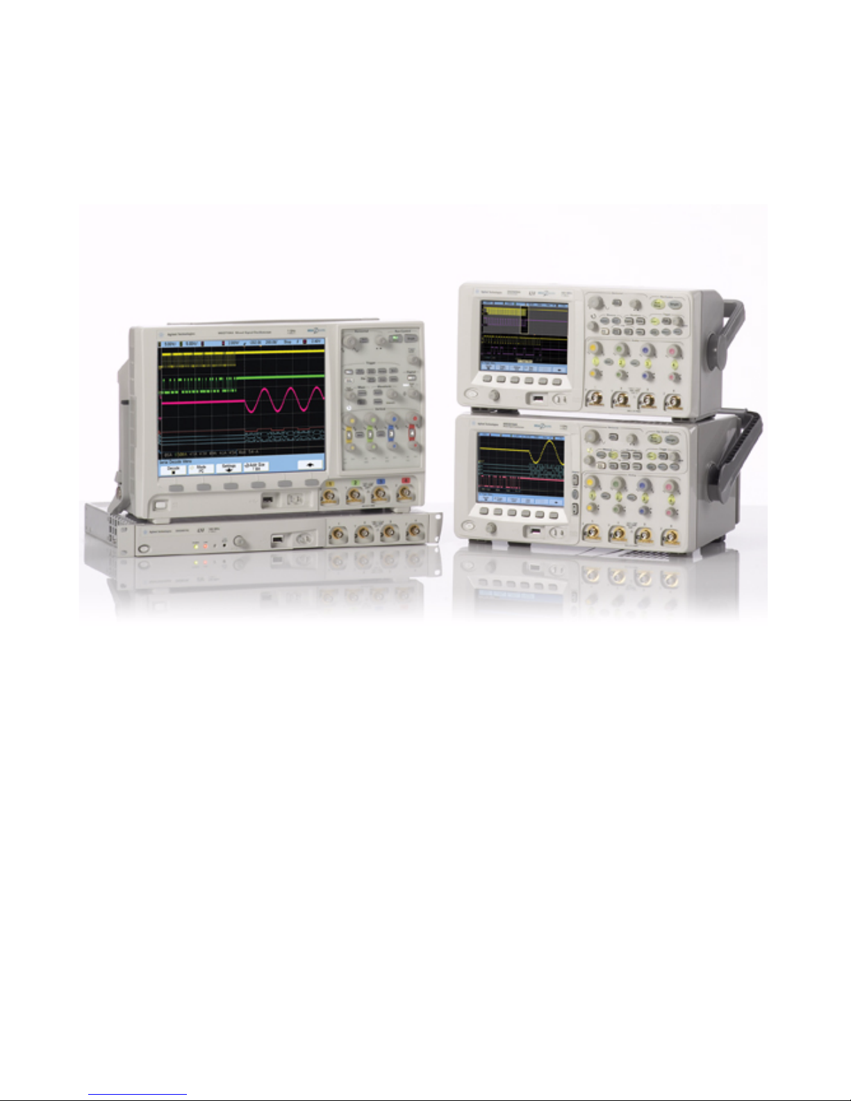
The Agilent InfiniiVision 5000, 6000, and 7000 Series oscilloscopes deliver
powerful features and high performance:
• 100 MHz, 300 MHz, 350 MHz, 500 MHz, and 1 GHz bandwidth models.
• Up to 4 GSa/s sample rate.
• 6.3 inch or 12.1 inch XGA display.
• Powerful triggering including analog HDTV, I
FlexRay, MIL-STD 1553, and USB.
• USB and LAN ports make printing, saving and sharing data easy. GPIB
ports on 5000 and 6000 Series models.
• 2-channel and 4-channel Digital Storage Oscilloscope (DSO) models.
• 2+16-channel and 4+16-channel Mixed Signal Oscilloscope (MSO)
models.
• An MSO lets you debug your mixed-signal designs using up to four
analog signals and 16 tightly correlated digital signals simultaneously.
• You can easily upgrade an InfiniiVision 6000 or 7000 Series
oscilloscope from a DSO to an MSO and/or add features such as
Segmented Memory and Mask Test.
2
C, I2S, SPI, LIN, CAN,
21
Page 22

1 Introduction
Agilent InfiniiVision oscilloscopes feature MegaZoom III technology:
• Most responsive deep memory.
• High definition color display.
• Largest display in its class (7000 Series, 12.1 inches).
• Fastest waveform update rates, uncompromised.
For more information about InfiniiVision oscilloscopes, see:
www.agilent.com/find/scope
Models Covered in this Manual
5000 SERIES MODEL NUMBERS, BANDWIDTHS, AND SAMPLING RATES
Bandwidth 100 MHz 300 MHz 500 MHz
Maximum Sample Rate 2GSa/s 2GSa/s 4GSa/s
2-Channel DSO DSO5012A DSO5032A DSO5052A
4-Channel DSO DSO5014A DSO5034A DSO5054A
6000 SERIES MODEL NUMBERS, BANDWIDTHS, AND SAMPLING RATES
Bandwidth 100 MHz 300 MHz 500 MHz 1 GHz
Maximum Sample Rate 2 GSa/s 2 GSa/s 4 GSa/s 4 GSa/s
2-Channel + 16 Logic Channels MSO MSO6012A MSO6032A MSO6052A MSO6102A
4-Channel + 16 Logic Channels MSO MSO6014A MSO6034A MSO6054A MSO6104A
2-Channel DSO DSO6012A DSO6032A DSO6052A DSO6102A
4-Channel DSO DSO6014A,
DSO6014L
DSO6034A DSO6054A,
DSO6054L
DSO6104A,
DSO6104L
22 InfiniiVision Oscilloscopes User’s Guide
Page 23

7000 S
ERIES MODEL NUMBERS, BANDWIDTHS, AND SAMPLING RATES
Bandwidth 100 MHz 350 MHz 500 MHz 1 GHz
Maximum Sample Rate 2 GSa/s 2 GSa/s 4 GSa/s 4 GSa/s
2-Channel + 16 Logic Channels MSO MSO7012A MSO7032A MSO7052A
4-Channel + 16 Logic Channels MSO MSO7014A MSO7034A MSO7054A MSO7104A
2-Channel DSO DSO7012A DSO7032A DSO7052A
4-Channel DSO DSO7014A DSO7034A DSO7054A DSO7104A
Specifications and Characteristics
Please see the InfiniiVision oscilloscope data sheets for complete, up-to-date
specifications and characteristics. To download a data sheet, please visit:
• www.agilent.com/find/5000
Introduction 1
• www.agilent.com/find/6000
• www.agilent.com/find/7000
Then, select the Library tab, followed by Specifications.
Or, go to the Agilent home page at www.agilent.com and search for 5000, 6000, or 7000
series oscilloscopes data sheet.
To order a data sheet by phone, please contact your local Agilent office. The complete list
is available at: www.agilent.com/find/contactus or on page page 420.
InfiniiVision Oscilloscopes User’s Guide 23
Page 24

1 Introduction
Licensed Options
Many of the following licensed options can be easily installed without returning the
oscilloscope to a Service Center. Not all options can be installed on all models. See data
sheets for details. To see the list of options installed on your oscilloscope, press
[Utility]&Options&Licenses&Show license information.
U
Option Description Order
PGRADE OPTIONS
232 RS232/UART serial decode option
(for 4 channel or 4+16 channel
models only)
553 MIL-STD 1553 serial decode option
(for 4 channel or 4+16 channel
models only)
ALT N5434A FPGA dynamic probe for
Altera (MSO recommended)
AMS CAN/LIN automotive triggering and
decode (for 4 channel or 4+16
channel models only)
FPG N5406A FPGA dynamic probe for
Xilinx (MSO recommended)
FLX FlexRay trigger and decode (for 4
channel or 4+16 channel models
only). Includes mask limit test option
(LMT), segmented memory option
(SGM), and FlexRay physical layer
conformance test application option
(FRC)
Order N5457A after purchase (Option 232 at
time of purchase). You can easily install this
option yourself.
Order N5469A after purchase (Option 553 at
time of purchase). You can easily install this
option yourself.
N5434A with Option 001 (Oscilloscope-locked
license) or Option 002 (PC-locked license).
Software is installed on an external PC.
Order N5424A after purchase (Option AMS at
time of purchase). You can easily install this
option yourself.
N5406A with Option 001 (Oscilloscope-locked
license) or Option 002 (PC-locked license).
Software is installed on an external PC.
Order N5432C after purchase (Option FLX at
time of purchase). You can easily install this
option yourself. FlexRay triggering and decode
option.
FRC FlexRay Physical Layer Conformance
Test Application
LMT Mask Limit Test Order N5455A after purchase (Option LMT at
24 InfiniiVision Oscilloscopes User’s Guide
Order U7244A. Application runs on a PC
connected to InfiniiVision oscilloscope.
time of purchase). You can easily install this
option yourself.
Page 25

UPGRADE OPTIONS (CONTINUED)
Option Description Order
Introduction 1
LSS I2C/SPI serial decode option (for 4
channel or 4+16 channel models only)
MSO Mixed Signal Oscilloscope (MSO).
Upgrade a DSO to an MSO.
PWR U1881A Power Application Order U1881A. Application runs on PC
SEC Secure Environment Mode Nonvolatile memory is cleared of all setup and
SGM Segmented Memory Order N5454A after purchase (Option SGM at
SND I2S serial decode option (for 4 channel
or 4+16 channel models only)
Order N5423A after purchase (Option LSS at
time of purchase). You can easily install this
option yourself.
Order N2735, N2736A, or N2737A. You can
easily install this option yourself. The logic
cable kit is supplied with the MSO license.
connected to InfiniiVision oscilloscope.
Optional U1880A deskew fixture available.
trace settings in compliance with National
Industrial Security Program Operation Manual
(NISPOM) Chapter 8 requirements. Available at
time of purchase only. See also
time of purchase). You can easily install this
option yourself.
Order N5468A after purchase (Option SND at
time of purchase). You can easily install this
option yourself.
page 402.
See also “Installed Licenses” on page 400.
CALIBRATION OPTION
Option Order
A6J ANSI Z540 Compliant Calibration
InfiniiVision Oscilloscopes User’s Guide 25
Page 26

1 Introduction
Notes
Built-in Quick Help
A Quick Help system is built into the oscilloscope. Press and hold any key to display Quick Help.
Complete instructions for using the quick help system are given on
Digital Channels
Because all of the oscilloscopes in the Agilent InfiniiVision Series have analog channels, the
analog channel topics in this book apply to all instruments. Whenever a topic discusses the digital
channels, that information applies only to Mixed-Signal Oscilloscope (MSO) models or DSO
models that have been upgraded to an MSO (available on the 6000 and 7000 Series oscilloscopes).
Abbreviated instructions for pressing a series of keys and softkeys
Instructions for pressing a series of keys are written in an abbreviated manner. Instructions for
pressing Key1, then pressing Softkey2, then pressing Softkey3 are abbreviated as follows:
[Key1]&Softkey2&Softkey3.
Press
The keys may be a front panel [Key] or a Softkey. Softkeys are the six keys located directly below
the oscilloscope display.
page 55.
Using this book with the 6000L Series oscilloscopes
The 6000L Series oscilloscopes do not have a built-in display or front panel control keys. If you are
using a 6000L Series oscilloscope, and this book refers to using front panel controls, you can use
the built-in Web control feature described on
complete the instructions.
“Accessing the Web Interface” on page 280 to
26 InfiniiVision Oscilloscopes User’s Guide
Page 27

Agilent InfiniiVision 5000/6000/7000 Series Oscilloscope
User’s Guide
2
Initial Setup
Package Contents 28
5000 Series Oscilloscope Package Contents 29
6000A Series Oscilloscope Package Contents 30
6000A Option BAT Oscilloscope Package Contents 31
6000L Series Oscilloscope Package Contents 32
7000A Series Oscilloscope Package Contents 33
Accessories Available 34
Tilt the oscilloscope up for easy viewing 36
To install the optional front panel overlay 40
To mount the oscilloscope in a rack 43
Ventilation Requirements 47
Power Requirements 48
Power-on the 5000/6000/7000 Series Oscilloscope 49
Power-on the Battery-Powered 6000A Series Oscilloscope 49
Verifying Basic Oscilloscope Operation 54
Quick Help 55
Graphical User Interface Languages 56
To set the clock 57
To set up the screen saver 58
Keys, Softkeys, and the Entry Knob 53
Using the Analog Channels 59
To set up the Horizontal time base 64
This chapter shows package contents for each oscilloscope model, and
explains how to set up the oscilloscope. Information about using the
analog channels and setting up the horizontal timebase is given. For an
overview of front panel controls see “Controls and Connectors” on
page 351.
27
Page 28

2 Initial Setup
Package Contents
✔ Inspect the shipping container for damage.
✔ Verify that you received the following items and any optional accessories you may
If your shipping container appears to be damaged, keep the shipping container or
cushioning material until you have inspected the contents of the shipment for
completeness and have checked the oscilloscope mechanically and electrically.
have ordered:
• InfiniiVision Oscilloscope
• Front-panel cover (all models except 6000L Series)
• Power cord (country of origin determines specific type)
• Oscilloscope probes
• Two probes for 2-channel models
• Four probes for 4-channel models
• CD-ROM containing:
• User’s Guide
• Service Guide
• Programmer’s Guide
• Automation-Ready Software CD-ROM
• Accessory pouch (7000 Series only)
• Digital probe kit P/N 54620-68701 (MSO Models only)
• Power Supply P/N 0950-4866 (6000 Option BAT only)
• LAN Crossover Cable 5061-0701 (6000L Series only)
• GPIB cable extender P/N 5183-0803 (6000L Series only)
• 50 ohm feedthrough termination adapter, Qty. 4, P/N 0960-0301 (DSO6014L only)
28 InfiniiVision Oscilloscopes User’s Guide
Page 29
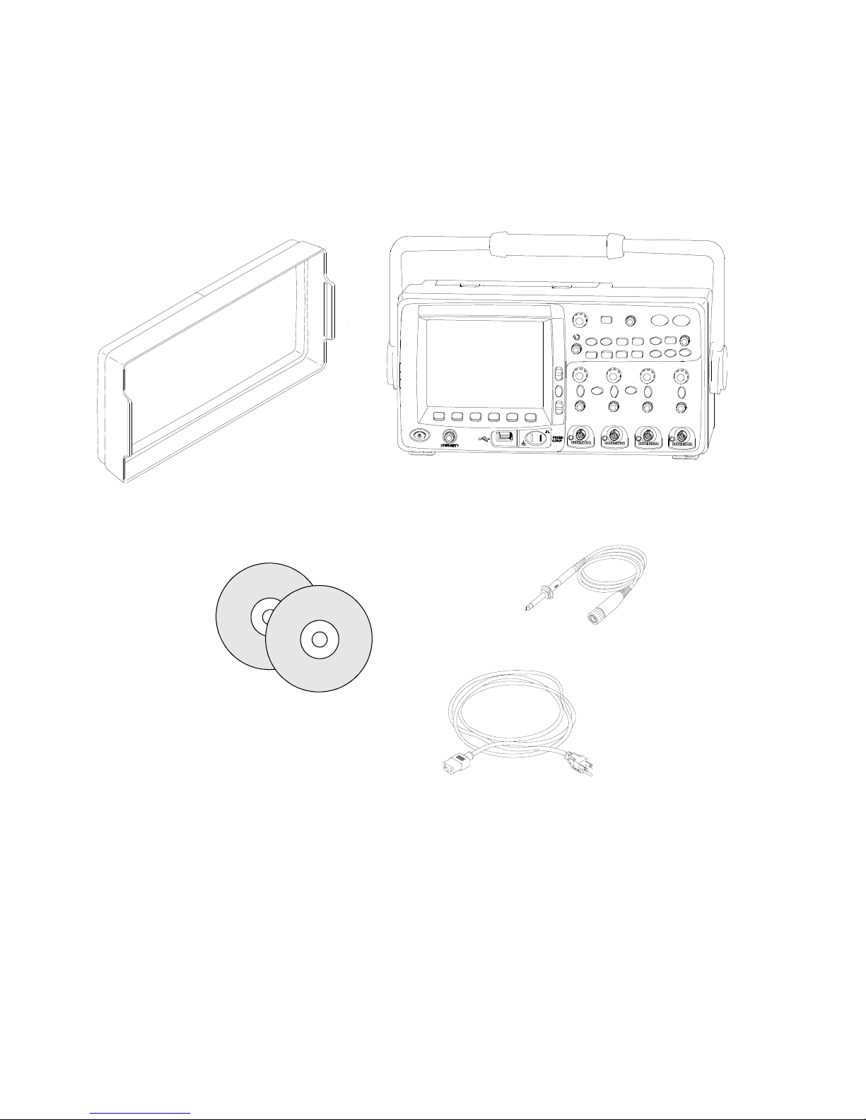
5000 Series Oscilloscope Package Contents
InfiniiVision 5000 Series
Oscilloscope
Oscilloscope probes
N2863A or 10073C
(Qty 2 or 4)
Power cord
(Based on country of
origin)
Front-panel cover
Documentation CD
Automation-Ready CD
Initial Setup 2
InfiniiVision Oscilloscopes User’s Guide 29
Page 30
2 Initial Setup
Power cord
(Based on country of
origin)
6000A Series
Oscilloscope
Front-panel cover
Oscilloscope probes
10073C or 10074C
(Qty 2 or 4)
Digital Probe Kit*
(MSO models only)
Digital
cable guide
(MSO models only)
*Digital Probe Kit contains:
54620-61801 16-channel cable (qty 1)
5959-9334 2-inch probe ground leads (qty 5)
5090-4833 Grabber (qty 20)
Digital probe replacement parts are listed on
page 389
Documentation CD
Automation-Ready CD
6000A Series Oscilloscope Package Contents
30 InfiniiVision Oscilloscopes User’s Guide
Page 31

6000A Option BAT Oscilloscope Package Contents
AC/DC power adapter
Front-panel cover
6000A Series Option BAT
Oscilloscope
Power cord
(see Power Cords
table)
Oscilloscope probes
10073C or 10074C
(Qty 2 or 4)
Documentation CD
Automation-Ready CD
Digital Probe Kit*
(MSO models only)
Digital cable guide
(MSO models only)
Ground wire
*Digital Probe Kit contains:
54620-61801 16-channel cable (qty 1)
5959-9334 2-inch probe ground leads (qty 5)
5090-4833 Grabber (qty 20)
Digital probe replacement parts are listed on
page 389
Initial Setup 2
InfiniiVision Oscilloscopes User’s Guide 31
Page 32
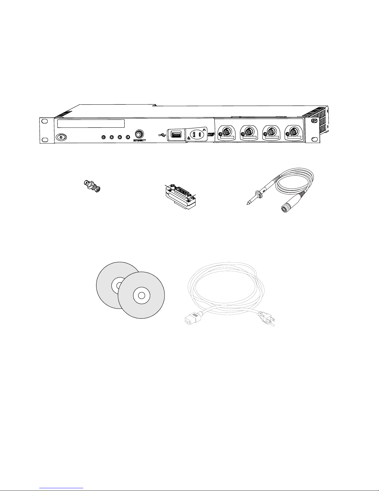
2 Initial Setup
6000L Series Oscilloscope
Oscilloscope Probes
10073C or 10074C
Qty. 4
Power cord
(Based on country of
origin)
50 ohm feedthrough
termination adapter
P/N 0960-0301, Qty. 4
GPIB cable extender
P/N 5183-0803
Rack Mount Kit
(not shown)
Documentation CD
Automation-Ready CD
6000L Series Oscilloscope Package Contents
32 InfiniiVision Oscilloscopes User’s Guide
Page 33
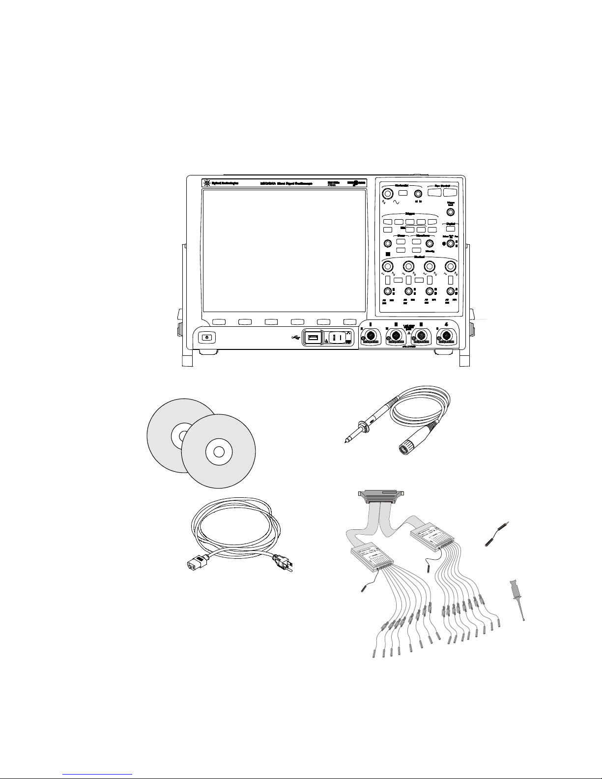
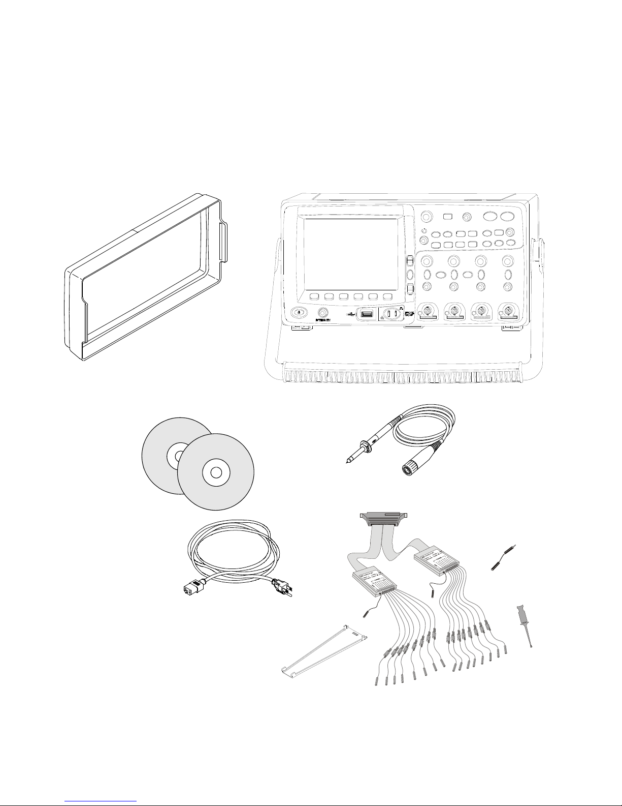
7000A Series Oscilloscope Package Contents
Power cord
(Based on country
of origin)
*Digital Probe Kit contains:
54620-61801 16-channel cable (qty 1)
5959-9334 2-inch probe ground leads (qty 5)
5090-4833 Grabber (qty 20)
Digital probe replacement parts are listed on page 389.
InfiniiVision 7000 Series oscilloscope
Front-panel cover and
accessory pouch
(not shown)
10073C or 1165A
probes
(Qty 2 or 4)
Digital Probe Kit*
(MSO models only)
Documentation CD
Automation-Ready CD
Initial Setup 2
InfiniiVision Oscilloscopes User’s Guide 33
Page 34

2 Initial Setup
Accessories Available
Model Description
N2918A 6000/7000 Series Oscilloscope Evaluation Kit
N2916B 5000/6000 Series Oscilloscope Rackmount Kit
N2732A 7000 Series Oscilloscope Rackmount Kit
54684-44101 5000/6000 Front Panel Cover
54913-44101 7000 Front-Panel Cover
various Front Panel Overlays - see
N2760A 5000 Soft Carrying Case
N2717B 5000 Transit Case
N2733A 7000 Soft Carrying Case
N2734A Transit Case
1180CZ Testmobile Oscilloscope Cart for 6000 Series (requires N2919A adapter kit)
N2919A Testmobile Adapter kit for 6000 Series oscilloscopes
N2605A-097 USB Cable
10833A GPIB Cable (5000 and 6000 models only)
5061-0701 LAN Crossover Cable
54620-68701 Digital Probe Kit (standard with MSO models)
54684-42301 Digital Probe Cable Guide (cable tray) 6000 models only
01650-61607 Logic Cable and Terminator (use with 40-pin logic analyzer accessories)
0960-0301 50-Ohm Termination Feedthrough (only for 6000 Series 100 MHz models)
10070C Passive Probe, 1:1 20 MHz, 1.5 m
10074C Passive Probe, 10:1, 150 MHz, 1.5 m
10073C Passive Probe, 10:1, 500 MHz, 1.5 m
1165A Passive Probe, 10:1, 600 MHz, 1.5 m
10076A Passive Probe, 100:1, 4 kV, 250 MHz
N2863A Passive Probe, 10:1, 300 MHz, 1.2 m
N2771A Passive Probe, 1000:1, 30 kV, 50 MHz
N2790A High-Voltage Differential probe, 50:1 or 500:1 (switchable), 100 MHz
N2786A 2-legged Probe Positioner
N2784A 1-arm Probe Positioner
N2785A 2-arm Probe Positioner
N2880A InfiniiMax In-line Attenuator kit, pair of 6 dB, 12 dB, and 20 dB attenuators in kit,
N2881A InfiniiMax DC blocking caps (qty 2), withstand up to 30 V dc, to be used with
N2882A 75 ohm-to-50 ohm adapter, dc to 8 GHz bandwidth, 5.7 dB attenuation
page 40, page 41, page 42.
to be used with InfiniiMax probe amplifiers and heads
InfiniiMax probe amplifiers and heads
34 InfiniiVision Oscilloscopes User’s Guide
Page 35

Initial Setup 2
Model Description
W2637A LPDDR BGA probe, x16, 404 MHz, 100 ohm input impedance
W2638A LPDDR BGA probe, x32, 404 MHz , 100 ohm input impedance
W2639A Oscilloscope Adapter Board, 1.5 GHz, 75 ohm input impedance
N5450A InfiniiMax Extreme Temperature Extension Cables, to be used with InfiniiMax
probe amplifiers and heads, 92 cm (36 in)
N2791A Differential probe, 1 MOhm termination, 10:1 or 100:1 (switchable), 25 MHz
N2792A Differential probe, 50 Ohm termination, 10:1, 200 MHz, compatible with all
InfiniiVision models except 6000 Series 100 MHz models (MSO/DSO601x)
N2793A Differential probe, 50 Ohm termination, 10:1, 800 MHz, compatible with all
InfiniiVision models except 6000 Series 100 MHz models (MSO/DSO601x)
1156A Active Probe, 1.5 GHz
1144A Active Probe, 800 MHz (requires 1142A – power supply)
†
1145A
†
1130A
N2772A Active Differential Probe, 20 MHz, 1.2 kVDC + peak AC max (requires N2773A
1141A Active Differential Probe, 200 MHz, 200 VDC + peak AC max (requires 1142A
1146A Current Probe, 100 kHz, 100 A, AC/DC
†
1147A
N2780A Current Probe, 2 MHz, 500 A, AC/DC (use with N2779A power supply)
N2781A Current Probe, 10 MHz, 150 A, AC/DC (use with N2779A power supply)
N2782A Current Probe, 50 MHz, 30 A, AC/DC (use with N2779A power supply)
N2783A Current Probe, 100 MHz, 30 A, AC/DC (use with N2779A power supply)
10072A Fine-Pitch Probe Kit
10075A 0.5 mm IC Clip Kit
10076A 100:1, 4 kV 250 MHz Probe
E2613B 0.5 mm Wedge Probe Adapter, 3-signal, qty 2
E2614A 0.5 mm Wedge Probe Adapter, 8-signal, qty 1
E2615B 0.65 mm Wedge Probe Adapter, 3-signal, qty 2
E2616A 0.65 mm Wedge Probe Adapter, 8-signal, qty 1
E2643A 0.5 mm Wedge Probe Adapter, 16-signal, qty 1
E2644A 0.65 mm Wedge Probe Adapter, 16-signal, qty 1
†
Indicates a maximum of two of this model probe can be connected to each oscilloscope due to
AutoProbe interface current supply limitation. See also
Active Probe, 750 MHz 2-ch (requires 1142A – power supply)
For active differential probes: 1.5 GHz InfiniiMax amplifier (requires one or more
InfiniiMax probe head – E2675A, E2668A, E2669A).
power supply)
power supply)
Current Probe, 50 MHz, 30 A, AC/DC with AutoProbe interface
“Passive Probes” on page 73 and
“Active Probes” on page 74.
InfiniiVision Oscilloscopes User’s Guide 35
Page 36

2 Initial Setup
You can find these items at www.agilent.com
For information on more probes and accessories see “5989-6162EN Probes and
Accessories Selection Guide” and “5968-8153EN 5000 and 6000 Series Oscilloscope
Probes and Accessories Data Sheet,” available at www.agilent.com.
Tilt the oscilloscope up for easy viewing
The oscilloscope can be tilted up for easier viewing.
To tilt the 5000 Series oscilloscope up for easy viewing
The oscilloscope’s handle affects the tilt. The handle can be locked in one of three
positions:
• up, for carrying
• back, so the handle is out of the way
• down, so the oscilloscope can be tilted back for easy viewing when the oscilloscope is
on the floor and you are standing above it.
or at www.parts.agilent.com.
1 To rotate the handle, grasp the handle hubs on each side of the instrument and pull the
hubs out until they stop.
2 Without releasing the hubs, rotate the handle to the desired position. Then release the
hubs. Continue rotating the handle until it clicks into a set position.
36 InfiniiVision Oscilloscopes User’s Guide
Page 37
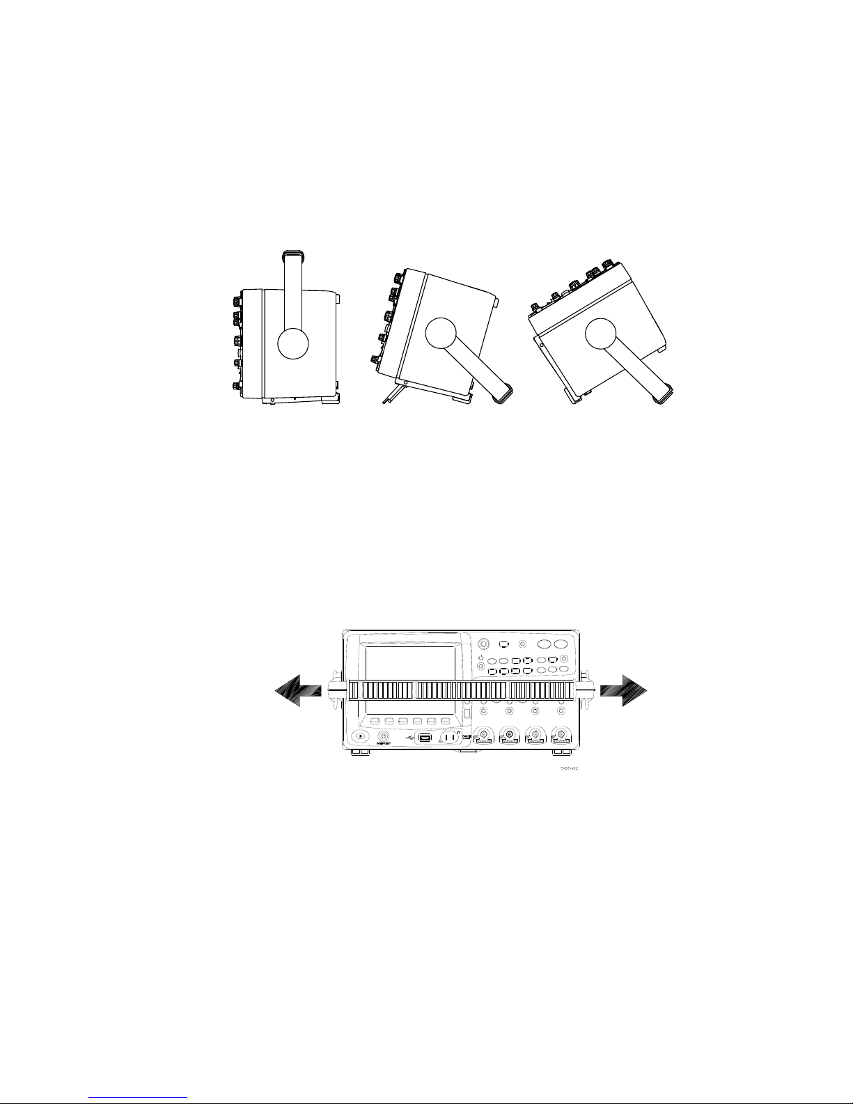
Initial Setup 2
The tilt tabs (underneath the oscilloscope) can be positioned as shown in the center
picture below. The handle can be used as a stand when placing the oscilloscope on a
floor, as shown in the picture on the right.
To tilt the 6000 Series oscilloscope up for easy viewing
You can use the oscilloscope’s handle for carrying the instrument, or you can use it as a
stand to tilt the instrument up for easier viewing of its display.
1 Grasp the handle hubs on each side of the instrument and pull the hubs out until they
stop.
InfiniiVision Oscilloscopes User’s Guide 37
Page 38
2 Initial Setup
2 Without releasing the hubs, rotate the handle to the desired position. Then release the
hubs. Continue rotating the handle until it clicks into a set position.
To tilt the 7000 Series oscilloscope up for easy viewing
1 Tilt the oscilloscope forward. Rotate the foot down and toward the rear of the
oscilloscope. The foot will lock into place.
2 Repeat for the other foot.
38 InfiniiVision Oscilloscopes User’s Guide
Page 39

3 Rock the oscilloscope back so that it rests securely on its feet.
To retract the feet
Initial Setup 2
1 Tilt the oscilloscope forward. Press the foot release button and rotate the foot up and
toward the front of the oscilloscope.
2 Repeat for the other foot.
InfiniiVision Oscilloscopes User’s Guide 39
Page 40
2 Initial Setup
Removal
Ta b
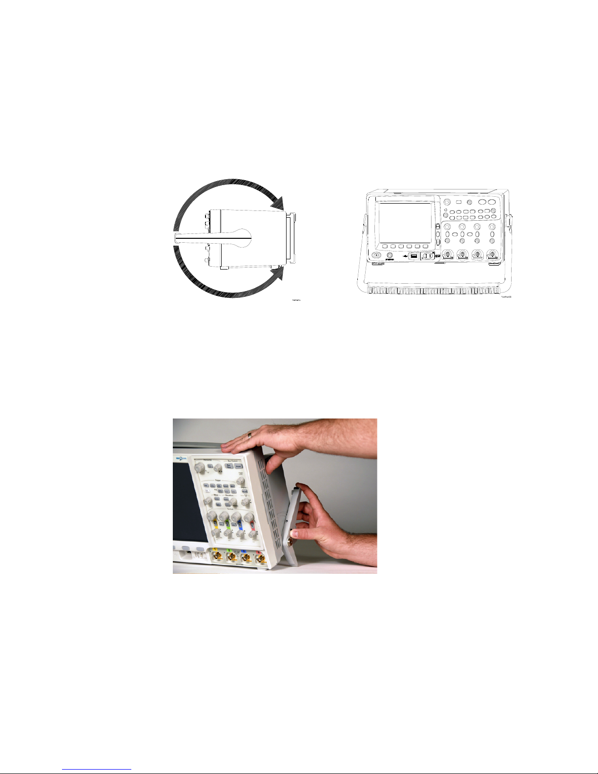
To install the optional front panel overlay
5000 Series Overlay
When Option AB0 (Traditional Chinese localization) or Option AB2 (Simplified Chinese
localization) is chosen at time of purchase, front panel overlays with Traditional Chinese
or Simplified Chinese text are provided. When Option ABJ (Japanese localization) is
ordered, a Japanese front panel overlay is provided.
Remove the protective backing to expose the adhesive, align the label with the top and
left edge of the front panel, and press the overlay into place.
To remove the label, carefully pull it away using the tab at the lower right corner.
The overlays will be available at www.parts.agilent.com using the following part
numbers:
Part number
54574-94306 Overlay - Simplified Chinese
54574-94307 Overlay - Traditional Chinese
54574-94308 Overlay - Japanese
Description
40 InfiniiVision Oscilloscopes User’s Guide
Page 41

Initial Setup 2
Removal
Ta b
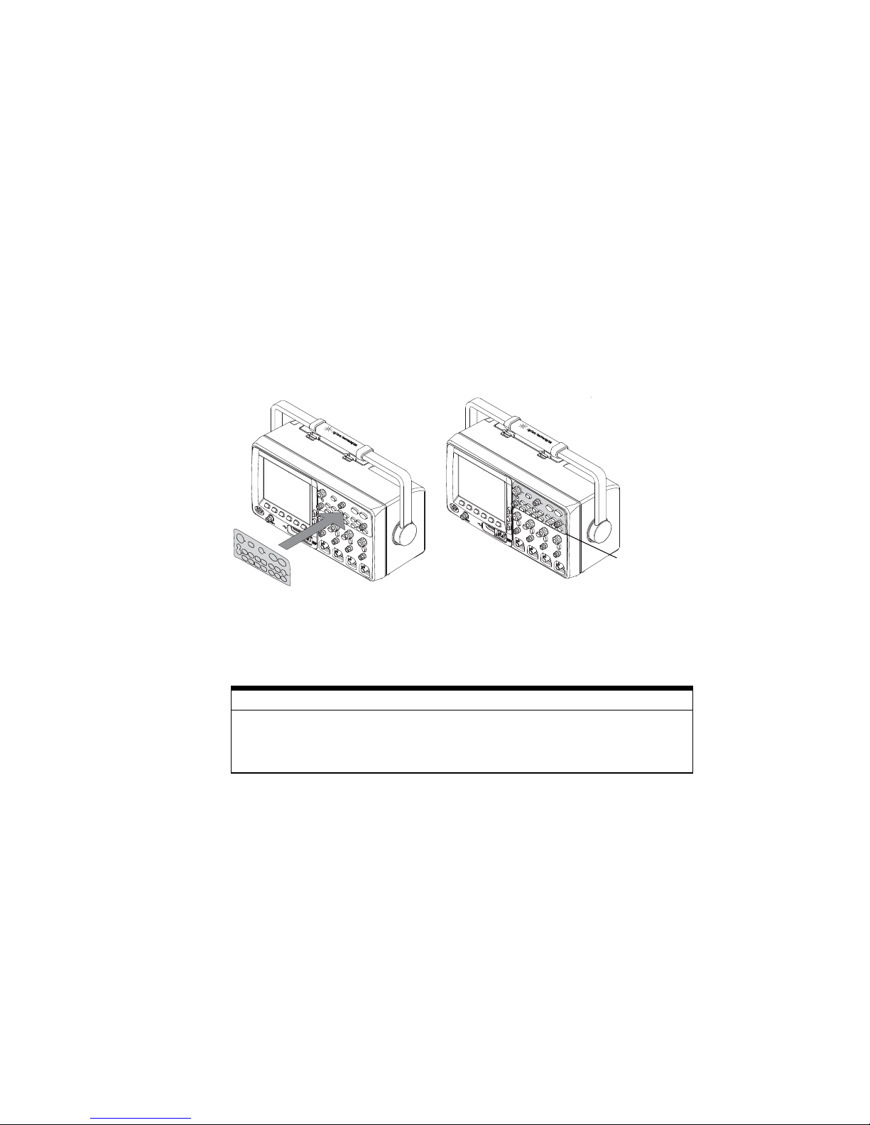
6000 Series Overlay
Large label: Remove the protective backing to expose the adhesive, align the label with
the top and left edge of the front panel, and press the overlay into place.
Small Label: Remove the protective backing, and affix over existing label. Note: the
cut-outs at the top of the label are for indicators on battery operated units.
To remove the label, carefully pull it away using the tab at the lower right corner.
The overlays will be available at www.parts.agilent.com using the following part
numbers:
Part number
54684-94316 Overlay - Simplified Chinese
54684-94317 Overlay - Traditional Chinese
54684-94318 Overlay - Japanese
Description
InfiniiVision Oscilloscopes User’s Guide 41
Page 42

2 Initial Setup
Removal
Ta b
7000 Series Overlay
A front panel overlay which labels the controls is available in Simplified Chinese,
Traditional Chinese, and Japanese. The overlay is included when the localization option is
chosen at time of purchase.
Remove the protective backing to expose the adhesive, align the label with the top and
left edge of the front panel, and press the overlay into place.
To remove the label, carefully pull it away using the tab at the lower right corner.
The overlays can also be ordered separately at www.parts.agilent.com using the
following part numbers:
Part number
54695-94311 2CH Overlay - Simplified Chinese
54695-94312 4CH Overlay - Simplified Chinese
54695-94313 2CH Overlay - Traditional Chinese
54695-94314 4CH Overlay - Traditional Chinese
54695-94315 2CH Overlay - Japanese
54695-94316 4CH Overlay - Japanese
Description
42 InfiniiVision Oscilloscopes User’s Guide
Page 43

To mount the oscilloscope in a rack
The InfiniiVision oscilloscopes can be mounted in an Electronic Industries Association
(EIA) standard 19-inch (487-mm) rack cabinet.
To mount the 5000 or 6000 Series oscilloscope in a rack
To mount the oscilloscope in a rack, purchase and install the N2916B rack mount kit.
Instructions are included in the kit. For details search for N2916B at www.agilent.com.
To mount the 6000L Series oscilloscope in a rack
The 6000L Series oscilloscope is supplied with all necessary hardware for installation
into a standard EIA 19-inch rack.
RACK MOUNT HARDWARE SUPPLIED
Initial Setup 2
Quantity Description Agilent Part
Number
2 Front Extender Support D6104-01201
2 Rear Extender Support D6104-01202
4 Rear Extender Screw (M3 x 6 mm) 0515-0430
4 Dress Screw (10-32 x 0.0625) 0570-1577
8 Rail Screw (10-32 x 0.375) 2680-0281
12 Clip-nut (10-32) 0590-0804
TOOLS REQUIRED (NOT SUPPLIED)
• #2 Phillips screwdriver
• T20 Torx driver
• T10 Torx driver
InfiniiVision Oscilloscopes User’s Guide 43
Page 44

2 Initial Setup
Step 1,
step 5
Step 2
If needed
If needed
Step 4
Step 3
1 Loosely attach the Front Extender Supports to the Rear Extender Supports with four
(4) clip-nuts and four (4) of the 10-32 x 0.375 Rail Screws. (The screws require a Torx
T20 driver.) Choose the correct set of slots in the supports such that their overall
length is approximately correct for the depth of your cabinet.
2 Fasten the Rack Mount Extenders to the oscilloscope chassis with the four (4) M3 x 6
mm screws, using a Torx T10 driver as follows:
44 InfiniiVision Oscilloscopes User’s Guide
Page 45

Initial Setup 2
NOTE
Use outer
holes in
extender
Use inner
holes in
extender
The sets of holes in the Rack Mount Extenders are slightly offset. This was done to
ensure that the Rack Mount Extenders are attached to the oscilloscope at the correct
points so that the oscilloscope’s ventilation area is not obscured. The holes in the Rack
Mount Extenders will align with the correct holes in the oscilloscope and the screws will
go in easily. Do not force the screws into the wrong holes.
a Attach a Rack Mount Extender to the left side of the oscilloscope using two (2) of
the M3 x 6 mm screws in the inner set of holes on the Rack Mount Extender.
b Attach the other Rack Mount Extender to the right side of the oscilloscope using
two (2) of the M3 x 6 mm screws in the outer set of holes on the rack mount
extender.
3 Place the instrument in the rack. Install the four (4)
10-32 x 0.625 Dress Screws in the chassis front ears to secure the front of the
instrument to the rack. Use the Phillips screwdriver.
4 Align the ears in the Rear Mount Extenders with the correct set of holes in the rear of
the rack and secure the Rack Mount Extenders to the rack using the four (4) remaining
10-32 x 0.375 Rail Screws. Use the Torx T20 driver.
5 Securely attach the Rear Extender Supports to the Front Extender Supports by
tightening the four (4) 10-32 x 0.375 Rail Screws screws that you loosely attached in
step 1.
InfiniiVision Oscilloscopes User’s Guide 45
Page 46

2 Initial Setup
6000L Mounting Bracket Dimensions
The following information is provided in case you want to design custom mounting
brackets for the 6000L. Dimensions are in mm.
To mount the 7000 Series oscilloscope in a rack
To mount the oscilloscope in a rack, purchase and install the N2732A rack mount kit.
Instructions are included in the kit. For details search for N2732A at www.agilent.com.
46 InfiniiVision Oscilloscopes User’s Guide
Page 47

Ventilation Requirements
The air intake and exhaust areas must be free from obstructions. Unrestricted air flow is
required for proper cooling. Always ensure that the air intake and exhaust areas are free
from obstructions.
5000 and 6000A Series Ventilation Requirements
The fan draws air in from underneath the oscilloscope and pushes it out behind the
oscilloscope.
When using the oscilloscope in a bench-top setting, provide at least 4" (100 mm)
clearance behind and above the oscilloscope for proper cooling.
6000L Series Ventilation Requirements
The fan draws air from the left and pushes it out to the right. Ensure the rack in which the
oscilloscope is mounted is properly ventilated.
Initial Setup 2
7000 Series Ventilation Requirements
The fan draws air in from the sides of the oscilloscope and pushes it out behind the
oscilloscope.
When using the oscilloscope in a bench-top setting, provide at least 2” clearance at the
sides and 4" (100 mm) clearance above and behind the oscilloscope for proper cooling.
InfiniiVision Oscilloscopes User’s Guide 47
Page 48

2 Initial Setup
Power Requirements
5000, 6000A (without Option BAT), and 7000 Line voltage, frequency, and power
~Line 100-120 Vac, 50/60/400 Hz
100-240 Vac, 50/60 Hz
120 W max
6000A with Option BAT
AC power supply/charger line voltage, frequency, and power
~Line 100-240 Vac, 50/60 Hz
120 W max
6000A with Option BAT
DC input voltage and power consumption using N5429A automotive adapter
12 Vdc nominal, (10-18 Vdc)
67-75 W
External ground connection required. See warning on page 51.
6000L Models Line voltage, frequency, and power
~Line 100-240 Vac, 50/60 Hz
80 W max
48 InfiniiVision Oscilloscopes User’s Guide
Page 49
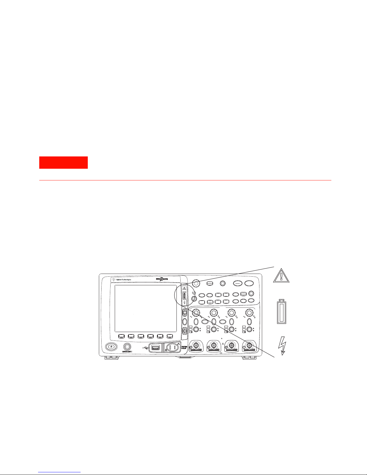
Power-on the 5000/6000/7000 Series Oscilloscope
WARNING
Digital
Select
Position
54684A
Oscilloscope
1 GHz
4 GSa/s
Analog
1234
CAT
I
300 V RMS
~
~
14pF
1 M
50
5 V RMS
AC
BW
50
AC
BW
50
AC
BW
50
AC
BW
50
XY Z
Main
Delayed
Single
Mode
Coupling
Stop
Run
Edge
Pulse
Width
Pattern
More
Cursors
Quick
Meas
Acquire
Display
AutoScale
Save
Recall
Quick
Print
Utility
1
2
Math
Label
3
4
D15
D0
Thru
54684e82
1 Connect the power cord to the rear of the oscilloscope, then to a suitable AC voltage
source. Route the power cord so the oscilloscope’s feet and legs do not pinch the
cord.
The oscilloscope automatically adjusts for input line voltages in the range 100 to 240
VAC. The line cord provided is matched to the country of origin.
Always use a grounded power cord. Do not defeat the power cord ground.
2 Press the power switch.
The power switch is located on the lower left corner of the front panel. The
oscilloscope will perform a self-test and will be operational in a few seconds.
Initial Setup 2
Power-on the Battery-Powered 6000A Series Oscilloscope
The 6000A Series Option BAT oscilloscopes are battery powered. They have additional
InfiniiVision Oscilloscopes User’s Guide 49
LED indicators on the front panel:
Page 50

2 Initial Setup
Caution indicator. Illuminates (amber) when running
on the internal battery. See “Operating” below.
Battery power indicator. Turns from green to red when
there is 15 to 20 minutes of battery power remaining.
Charging indicator. Illuminates when the battery is
charging. Turns off when the battery is fully charged or
when the charger is disconnected.
The battery will last approximately 1.75 hours before requiring recharging. Operating time
depends on the oscilloscope configuration.
Operating
When operating with the internal battery, the operating temperature should be in the
range from -10C to 50C, 80% relative humidity. Low temperatures temporarily reduce
battery capacity.
1 Make sure battery is charged before use. See “Charging the Battery” below.
50 InfiniiVision Oscilloscopes User’s Guide
Page 51
Initial Setup 2
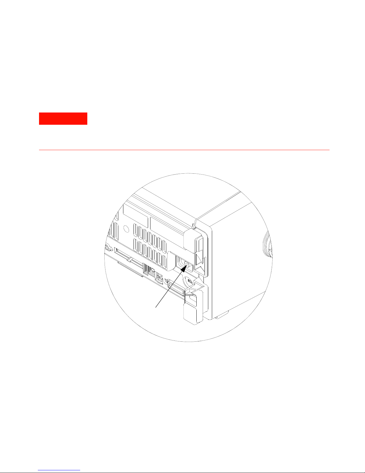
WARNING
Ground Post
2 Always connect the supplied ground wire from the ground post on the back of the
instrument to earth ground (even when connected to an AC or DC adapter for
charging/operating the instrument).
Maintain oscilloscope ground connection. Do not negate the protective action of
the ground connection to the oscilloscope. If the circuit under test has voltages
greater than 30 Vrms, the oscilloscope must be grounded through its ground post
(on Option BAT models) to prevent electric shock to the user.
3 Press the power switch.
The power switch is located on the lower left corner of the front panel. Some front
panel lights will come on and the oscilloscope will be operational in a few seconds.
InfiniiVision Oscilloscopes User’s Guide 51
Page 52

2 Initial Setup
CAUTION
NOTE
Charging the Battery
When charging the battery, the operating temperature should be in the range from 0C to
45C, 80% relative humidity.
1 Connect the supplied AC adapter to the back of the oscilloscope, and connect the
adapter’s power cord to a suitable AC voltage source.
AC adapter for battery-powered oscilloscopes: Use only the supplied adapter.
Damage to the equipment could result if an improper AC adapter is used.
You can use the oscilloscope while the battery is being charged.
If the battery charging indicator does not light
If the battery is extremely discharged, there may not be enough charge for internal
circuitry to cause the battery charging indicator LED to light. In this case, it can take up to
about 20 minutes of charging before the indicator will light.
Operating with the Automotive Power Adapter Cable
The N5429A 12V DC automotive adapter cable is for charging and operating 6000A Series
Option BAT battery-powered oscilloscopes.
1 Connect the N5429A adapter cable to the back of the oscilloscope, and connect the
other end of the cable to a 12V DC automotive power source.
Battery Replacement
The battery (actually two batteries) can be replaced by a qualified technician. Refer to the
service guide for replacement instructions. The service guide is available on the CD that
was included with the oscilloscope at time of purchase, and at
www.agilent.com/find/6000manual.
Battery Warranty
The battery is warranted for a period of one year from date of purchase.
52 InfiniiVision Oscilloscopes User’s Guide
Page 53

Keys, Softkeys, and the Entry Knob
NOTE
On the front panel, “key” refers to any key (button) you can press. “Softkey” specifically
refers to the six keys that are directly below the display. The legend for these keys is
directly above them, on the display. Their functions change as you navigate through the
oscilloscope’s menus.
In this manual, instructions for pressing a series of keys are written in an abbreviated
manner. Pressing the [Utility] key, then the Language softkey, then the Help softkey is
abbreviated as follows:
Press [Utility]&Language&Help.
Press and hold any key or softkey to view its built-in Quick Help.
When the Entry knob symbol appears on a softkey, you can use the Entry knob, to
select values.
For easy one-handed operation of the 7000 Series oscilloscopes, the Entry knob can be
pushed as well as rotated. Rotating the knob moves through selectable items, and
pushing the knob implements the selection.
Initial Setup 2
Six softkeys are located below the display. To understand the symbols used in the softkey
menus and throughout this guide, see “Graphic Symbols in Softkey Menus” on
page 176.
The Digital Channel Controls are used to select and reposition digital channel waveforms
and to display the Digital Channel Menu of MSO model oscilloscopes.
The simplest way to set up the oscilloscope is to connect it to the signals of interest and
press the [AutoScale] key.
To find out how to use a key or connector, see “Controls and Connectors” on page 351.
InfiniiVision Oscilloscopes User’s Guide 53
Page 54
2 Initial Setup
Verifying Basic Oscilloscope Operation
If you have a 6000L Series oscilloscope, you need to start a Web control session, as
described in “Accessing the Web Interface” on page 280.
1 Press the [Save/Recall] key on the front panel, then press the Default Setup softkey
([Save/Recall]&Default Setup). The oscilloscope is now configured to its default
settings (configuration details on page 392).
2 Connect an oscilloscope probe from channel 1 to the Probe Comp terminal on the
front panel.
3 Connect the probe’s ground lead to the ground terminal (next to the Probe Comp
terminal).
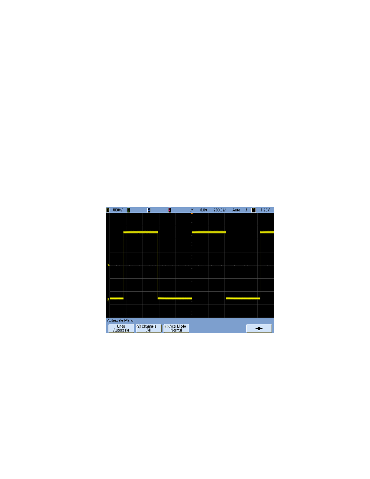
4 Press [AutoScale].
5 You should see a waveform on the oscilloscope’s display similar to this:
If you see the waveform, but the square wave is not shaped correctly as shown above,
perform the procedure “Compensating Passive Probes” on page 77.
If you do not see the waveform, ensure your power source is adequate, the oscilloscope
is powered-on, the power cord is firmly inserted into the oscilloscope receptacle, and the
probe is connected securely to the front-panel oscilloscope channel input BNC and to the
Probe Comp terminal.
54 InfiniiVision Oscilloscopes User’s Guide
Page 55

Quick Help
Press and Hold Front Panel Key or Softkey
(or Right-Click Softkey when using Web browser control)
Quick Help Message
Initial Setup 2
To view Q uick Help
1 Press and hold the key or softkey for which you would like to view help.
By default, Quick Help remains on the screen until another key is pressed or a knob is
turned. You can set Quick Help to close when you release the key. Press the [Utility] key,
then press the Language softkey, then press the Help Close on Release/Remain on
Screen softkey ([Utility]&Language&Help).
To view Quick Help on 6000L Series oscilloscopes
Start a Web browser control session as described on “Accessing the Web Interface” on
page 280 and select Remote Front Panel. To view Quick Help information, right-click on
the softkey. Help is not available for front panel keys; only softkeys.
InfiniiVision Oscilloscopes User’s Guide 55
Page 56

2 Initial Setup
Quick Help Languages
To choose a Quick Help language in the oscilloscope:
1 Press [Utility], then press the Language softkey.
2 Repeatedly press and release the Language softkey or rotate the Entry knob until the
desired language is selected.
Graphical User Interface Languages
When Quick Help is set to one of the following languages, the Graphical User Interface
(GUI) will be displayed in the language chosen.
• Simplified Chinese
• Traditional Chinese
• Japanese
• Korean
Quick Help Updates
Updated Quick Help may be made available. To download new Quick Help and GUI
language files:
1 Direct your web browser to:
www.agilent.com/find/6000sw (for 5000 and 6000 models)
www.agilent.com/find/7000sw (for 7000 models)
2 Select Quick Help Language Support and follow the directions.
56 InfiniiVision Oscilloscopes User’s Guide
Page 57
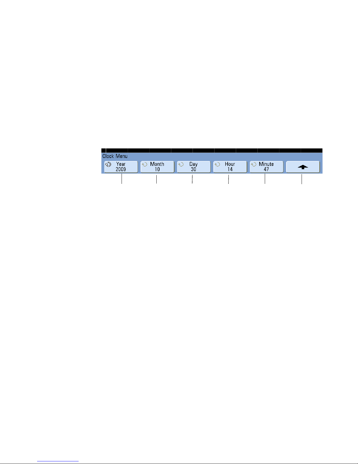
To set the clock
Year set Month set Return to
previous menu
Day set Hour set Minute set
Initial Setup 2
The Clock Menu lets you set the current date and time of day (24-hour format). This
time/date stamp will appear on hardcopy prints and directory information on the USB
mass storage device.
To set the date and time, or to view the current date and time:
1 Press [Utility]&Options&Clock.
2 Press the Ye a r, Month, Day, Hour or Minute softkey and rotate the Entry knob to set to
the desired number.
The hours are shown in the 24-hour format. So 1:00 PM is hour 13.
The real-time clock only allows selection of valid dates. If a day is selected and the month
or year is changed so the day is invalid, the day is automatically adjusted.
InfiniiVision Oscilloscopes User’s Guide 57
Page 58

2 Initial Setup
Screen saver
image
Screen saver
time delay
Return to
previous menu
Preview
Select
characters
Advance to next
character
List of characters displayed
when Entry knob is turned
User-defined
text string
To set up the screen saver
The oscilloscope can be configured to turn on a display screen saver when the
oscilloscope has been idle for a specified length of time.
1 Press [Utility]&Options&Preferences&Screen Saver to display the Screen Saver
Menu.
2 Press the Saver softkey to select the screen saver type.
The screen saver can be set to Off, to display any of the images shown in the list, or
can display a user-defined text string.
If User is selected, press the Spell softkey to select the first character of the text
string. Use the Entry knob to choose a character. Then press the Enter softkey to
advance to the next character and repeat the process. The resultant string is displayed
in the “Text =” line above the softkeys.
3 Turn the Entry knob to select the number of minutes to wait before the selected screen
saver activates.
When you turn the Entry knob, the number of minutes is displayed in the Wait softkey.
The default time is 180 minutes (3 hours).
58 InfiniiVision Oscilloscopes User’s Guide
Page 59

4 Press the Preview softkey to preview the screen saver you have selected with the
Channel
coupling
Invert
channel
Probe
menu
Trigger level
or threshold
Trigger
source
Channel,
Volts/div
Fine V/div
adjustment
Channel 2
ground level
Channel 1
ground level
Bandwidth
limit
Input
impedance
Saver softkey.
5 To view the normal display after the screen saver has started, press any key or turn any
knob.
Using the Analog Channels
1 Connect the oscilloscope probes for channels 1 and 2 to the Probe Comp output on the
front panel of the instrument.
2 Press the [1] key in the Analog section of the oscilloscope’s front panel to display the
Channel 1 Menu.
Initial Setup 2
InfiniiVision Oscilloscopes User’s Guide 59
Page 60

2 Initial Setup
Pressing an analog channel key displays the channel’s menu and turns the display of
the channel on or off. The channel is displayed when the key is illuminated.
Turning channels off
You must be viewing the menu for a channel before you can turn it off. For example, if channel 1
and channel 2 are turned on and the menu for channel 2 is being displayed, to turn channel 1 off,
press [1] to display channel 1 menu, then press [1] again to turn channel 1 off.
Vertical sensitivity Turn the large knob above the channel key marked to set the
sensitivity (volts/division) for the channel. The vertical sensitivity knob changes the
analog channel sensitivity in a 1-2-5 step sequence (with a 1:1 probe attached). The
analog channel Volts/Div value is displayed in the status line.
Fine Press the Fine softkey to turn on fine control V/div adjustment (vernier) for the
selected channel. When Fine is selected, you can change the channel’s vertical
sensitivity in smaller increments. The channel sensitivity remains fully calibrated when
Fine is on. The V/div value is displayed in the status line at the top of the display.
When Fine is turned off, turning the volts/division knob changes the channel sensitivity
in a 1-2-5 step sequence.
Vertical expansion The default mode for expanding the signal when you turn the
volts/division knob is vertical expansion about the ground level of the channel. To set the
expansion mode to expand about the center of the screen instead, press Expand in the
User Preferences Menu ([Utility]&Options&Preferences) and select Center.
Ground level The ground level of the signal for each displayed analog channel is
identified by the position of the icon at the far-left side of the display.
Vertical position Turn the small vertical position knob ( ) to move the channel’s
waveform up or down on the display. The voltage value momentarily displayed in the
upper right portion of the display represents the voltage difference between the vertical
center of the display and the ground level ( ) icon. It also represents the voltage at the
vertical center of the display if vertical expansion is set to expand about ground.
60 InfiniiVision Oscilloscopes User’s Guide
Page 61

Initial Setup 2
NOTE
Channel Coupling and Input Impedance Selection
Measurement Hints
If the channel is DC coupled, you can quickly measure the DC component of the signal by simply
noting its distance from the ground symbol.
If the channel is AC coupled, the DC component of the signal is removed, allowing you to use
greater sensitivity to display the AC component of the signal.
3 Press the channel’s on/off key, then press the Coupling softkey to select the input
channel coupling.
Coupling changes the channel's input coupling to either AC (alternating current) or DC
(direct current). AC coupling places a 3.5 Hz high-pass filter in series with the input
waveform that removes any DC offset voltage from the waveform. When AC is
selected, “AC” is illuminated on the front panel next to the channel position knob ( ).
• DC coupling is useful for viewing waveforms as low as 0 Hz that do not have large
DC offsets.
• AC coupling is useful for viewing waveforms with large DC offsets. When AC
coupling is chosen, you cannot select 50 mode. This is done to prevent damage
to the oscilloscope.
Note that Channel Coupling is independent of Trigger Coupling. To change trigger
coupling see page 87.
4 Press the Imped (impedance) softkey.
When you connect an AutoProbe, self-sensing probe, or a compatible InfiniiMax probe,
the oscilloscope will automatically configure the oscilloscope to the correct impedance.
The analog channel input impedance can be set to either 1M Ohm or 50 Ohm by
pressing the Imped softkey.
• 50 Ohm mode matches 50-ohm cables commonly used in making high frequency
measurements, and 50-ohm active probes. This impedance matching gives you the
most accurate measurements since reflections are minimized along the signal
path. When 50 Ohm is selected, “50” is illuminated on the front panel next to the
channel position knob. The oscilloscope automatically switches to 1 M Ohm mode
to prevent possible damage if AC coupling is selected.
InfiniiVision Oscilloscopes User’s Guide 61
Page 62

2 Initial Setup
Attenuation
factor
Measurement
units
Skew adjust
Return to
previous menu
Calibrate
probe
Probe calibration not needed, not available when this softkey is ghosted.
• 1M Ohm mode is for use with many passive probes and for general-purpose
measurements. The higher impedance minimizes the loading effect of the
oscilloscope on the device under test.
5 Press the BW Limit softkey to turn on bandwidth limiting.
Pressing the BW Limit softkey turns the bandwidth limit on or off for the selected
channel. When bandwidth limit is on, the maximum bandwidth for the channel is
approximately 25 MHz. For waveforms with frequencies below this, turning bandwidth
limit on removes unwanted high frequency noise from the waveform. The bandwidth
limit also limits the trigger signal path of any channel that has BW Limit turned on.
When BW Limit is selected, “BW” is illuminated on the front panel next to the
channel position knob ( ).
6 Press the Invert softkey to invert the selected channel.
When Invert is selected, the voltage values of the displayed waveform are inverted.
Invert affects how a channel is displayed, but does not affect triggering. If the
oscilloscope is set to trigger on a rising edge, it remains set to trigger on a same edge
(triggers at the same point on the waveform) after the channel is inverted.
Inverting a channel will also change the result of any function selected in the
Waveform Math Menu or any measurement.
7 Press the Probe softkey to display the Channel Probe Menu.
This menu lets you select additional probe parameters such as attenuation factor and
units of measurement for the connected probe.
• Probe Units — Press the Units softkey to select the proper measurement unit for
the connected probe. Select Volts for a voltage probe and select Amps for a current
probe. Channel sensitivity, trigger level, measurement results, and math functions
will reflect the measurement units you have selected.
62 InfiniiVision Oscilloscopes User’s Guide
Page 63

Initial Setup 2
• Probe Attenuation Factor— This is set automatically if the oscilloscope can
identify the connected probe. See “AutoProbe Interface” on page 72 and
“Manually Setting the Probe Attenuation Factor” on page 80.
• Skew — When measuring time intervals in the ns range, small differences in cable
length can affect the measurement. Use Skew to remove cable-delay errors
between any two channels.
Probe the same point with both probes, then press Skew and turn the Entry knob to
enter the amount of skew between channels. Each analog channel can be adjusted
±100 ns in 10 ps increments for a total of 200 ns difference.
The skew setting is not affected by pressing [Save/Recall]&Default Setup or by
pressing [Auto Scale].
• Calibrate Probe — See “Calibrating Probes” on page 78.
InfiniiVision Oscilloscopes User’s Guide 63
Page 64

2 Initial Setup
Normal
sweep mode
Zoom sweep
mode
Horiz. pos
knob mode
Time base
fine
adjustment
Trigger level
or threshold
Trigger
source
Delay
time
XY or Roll
mode
Time
reference
Sweep
speed
Trigger
point
Time
reference
Sample rate
To set up the Horizontal time base
1 Press the [Menu/Zoom] key (or [Main/Delayed] key on some oscilloscopes) in the
Horizontal section of the front panel.
The Horizontal Menu lets you select the horizontal mode (Normal, Zoom, XY, or Roll), and
set the time base fine adjustment and time reference.
The current sample rate is displayed above the Fine and Time Ref softkeys.
Normal mode
1 Press the Normal softkey to select Normal horizontal mode.
Normal horizontal mode is the normal viewing mode for the oscilloscope. When the
oscilloscope is stopped, you can use the Horizontal knobs to pan and zoom the
waveform.
2 Turn the large knob (time/division) in the Horizontal section and notice the change it
makes to the status line.
When the oscilloscope is running in Normal mode, use the large Horizontal knob
marked to change sweep speed and use the small knob marked to set the
delay time (horizontal position). When the oscilloscope is stopped, use these knobs to
pan and zoom your waveform. The sweep speed (seconds/division) value is displayed
in the status line.
64 InfiniiVision Oscilloscopes User’s Guide
Page 65

Initial Setup 2
3 Press the Fine softkey to turn on the time base fine adjustment.
The Fine softkey lets you change the sweep speed in smaller increments with the
time/division knob. The sweep speed remains fully calibrated when Fine is on. The
value is displayed in the status line at the top of the display.
When Fine is turned off, the Horizontal sweep speed knob changes the time base
sweep speed in a 1-2-5 step sequence.
4 Note the setting of the Time Ref (time reference) softkey.
Time reference is the reference point on the display for delay time (horizontal
position). The time reference can be set to one major division from the left or right
edge, or to the center of the display.
A small hollow triangle (
reference. When delay time is set to zero, the trigger point indicator () overlays the
time reference indicator.
Turning the Horizontal sweep speed knob will expand or contract the waveform about
the time reference point (). Turning the Horizontal position ( ) knob in Normal
mode will move the trigger point indicator () to the left or right of the time reference
point ().
The time reference position sets the initial position of the trigger event within
acquisition memory and on the display, with delay set to 0. The delay setting sets the
specific location of the trigger event with respect to the time reference position. The
time reference setting affects the Zoom sweep as described in the following ways:
• When the horizontal mode is set to Normal, the delay knob positions the normal
sweep relative to the trigger. This delay is a fixed number. Changing this delay value
does not affect the sweep speed.
• When the horizontal mode is set to Zoom, the delay knob controls the position of
the zoom sweep window inside the normal sweep display. This delay value is
independent of sampling interval and sweep speed. Changing this delay value does
not effect the position of the normal window.
5 Turn the delay knob ( ) and notice that its value is displayed in the status line.
at the top of the display grid marks the position of the time
The delay knob moves the normal sweep horizontally, and it pauses at 0.00 s,
mimicking a mechanical detent. Changing the delay time moves the sweep
horizontally and indicates how far the trigger point (solid inverted triangle) is from the
time reference point (hollow inverted triangle ). These reference points are indicated
along the top of the display grid. The previous figure shows the trigger point with the
InfiniiVision Oscilloscopes User’s Guide 65
Page 66

2 Initial Setup
delay time set to 400 s. The delay time number tells you how far the time reference
point is located from the trigger point. When delay time is set to zero, the delay time
indicator overlays the time reference indicator.
All events displayed left of the trigger point happened before the trigger occurred, and
these events are called pre-trigger information. You will find this feature very useful
because you can now see the events that led up to the trigger point. Everything to the
right of the trigger point is called post-trigger information. The amount of delay range
(pre-trigger and post-trigger information) available depends on the sweep speed
selected and memory depth.
Zoom mode
Zoom, formerly called Delayed sweep mode, is a horizontally expanded version of normal
display. When Zoom is selected, the display divides in half and the Zoom mode icon is
displayed in the middle of the line at the top of the display. The top half of the display
shows the normal sweep and the bottom half displays the Zoom sweep.
The Zoom window is a magnified portion of the normal sweep. You can use Zoom to
locate and horizontally expand part of the normal sweep for a more detailed
(higher-resolution) analysis of signals.
The following steps show you how to use Zoom.
1 Connect a signal to the oscilloscope and obtain a stable display.
2 Press the [Menu/Zoom] key (or [Main/Delayed] key on some oscilloscopes).
3 Press the Zoom softkey.
To change the sweep speed for the Zoom window, turn the horizontal sweep speed
control knob. As you turn the knob, the sweep speed is highlighted in the status line
above the waveform display area.
The area of the normal display that is expanded is outlined with a box and the rest of the
normal display is lightened. The box shows the portion of the normal sweep that is
expanded in the lower half. The Horizontal Sweep Speed controls the size of the box and
the Horizontal Position (delay time) control sets the left-to-right position of the zoom
sweep. The delay value, which is the time being displayed relative to the trigger point) is
momentarily displayed in the upper-right portion of the display when the delay time ( )
knob is turned. Negative delay values indicate you’re looking at a portion of the waveform
before the trigger event, and positive values indicate you’re looking at the waveform after
the trigger event.
To change the sweep speed for the normal sweep window, press the Normal softkey,
then turn the sweep speed knob.
66 InfiniiVision Oscilloscopes User’s Guide
Page 67

Initial Setup 2
Time/div for
normal
sweep
Time/div for
Zoom window
Delay time
momentarily displays
when the Horizontal
Position knob is turned
Select Normal
sweep or Zoom
Zoom
window
Normal
sweep
window
These markers define the
beginning and end of the
Zoom window
Signal
anomaly
expanded
in zoom
window
When the horizontal mode is set to Normal, the horizontal position control (delay control)
positions the normal sweep relative to the trigger. This delay is a fixed number. Changing
this delay value does not affect the sweep speed. When the horizontal mode is set to
Zoom, the delay controls the position of the zoom sweep window inside the normal
sweep display. This delay value is independent of sampling interval and sweep speed.
To change the sweep speed for the normal sweep window, press the Normal softkey,
then turn the sweep speed knob.
InfiniiVision Oscilloscopes User’s Guide 67
Page 68

2 Initial Setup
To specify the measurement window for Zoom mode When the zoomed time base
is displayed, you can specify whether the upper, Main window or the lower, Zoom
window is used as the measurement window.
1 Press [Utility] > Options > Preferences > More.
2 Press Window to select from these measurement window options:
• Auto Select – The measurement is attempted in the lower, Zoom window; if it
cannot be made there, the upper, Main window is used.
• Main – The measurement window is the upper, Main window.
• Zoom – The measurement window is the lower, Zoom window.
For information about using zoom mode for measurements, refer to Chapter 6,
“Measurements and Math Functions,” starting on page 191.
Roll mode
• Press the [Menu/Zoom] key (or [Main/Delayed] key on some oscilloscopes), then
press the XY or Roll softkey to select “Roll”.
• Roll mode causes the waveform to move slowly across the screen from right to left. It
only operates on time base settings of 500 ms/div and slower. If the current time base
setting is faster than the 500 ms/div limit, it will be set to 500 ms/div when Roll mode
is entered.
• In Normal horizontal mode, signal events occurring before the trigger are plotted to
the left of the trigger point (t) and signal events after the trigger plotted to the right of
the trigger point.
• In Roll mode there is no trigger. The fixed reference point on the screen is the right
edge of the screen and refers to the current moment in time. Events that have
occurred are scrolled to the left of the reference point. Since there is no trigger, no
pre-trigger information is available.
If you would like to pause the display in Roll mode press the [Single] key. To clear the
display and restart an acquisition in Roll mode, press the [Single] key again.
Use Roll mode on low-frequency waveforms to yield a display much like a strip chart
recorder. It allows the waveform to roll across the display.
68 InfiniiVision Oscilloscopes User’s Guide
Page 69

Initial Setup 2
XY mode
XY mode changes the display from a volts-versus-time display to a volts-versus-volts
display. The time base is turned off. Channel 1 amplitude is plotted on the X-axis and
Channel 2 amplitude is plotted on the Y-axis.
You can use XY mode to compare frequency and phase relationships between two
signals. XY mode can also be used with transducers to display strain versus
displacement, flow versus pressure, volts versus current, or voltage versus frequency.
Use the cursors to make measurements on XY mode waveforms.
For more information about using XY mode for measurements, refer to “XY Horizontal
Mode” on page 220.
Z-Axis Input in XY Display Mode (Blanking)
When you select the XY display mode, the time base is turned off. Channel 1 is the X-axis input,
channel 2 is the Y-axis input, and channel 4 (or the External trigger on 2-channel models) is the
Z-axis input. If you only want to see portions of the Y versus X display, use the Z-axis input. Z-axis
turns the trace on and off (analog oscilloscopes called this Z-axis blanking because it turned the
beam on and off). When Z is low (<1.4 V), Y versus X is displayed; when Z is high (>1.4 V), the
trace is turned off.
Knob softkey
The “Knob “softkey is used in conjunction with Segmented Memory. You can set the
Horizontal Position knob to adjust the horizontal position or move between segments.
See “Segmented Memory” on page 271.
InfiniiVision Oscilloscopes User’s Guide 69
Page 70

2 Initial Setup
70 InfiniiVision Oscilloscopes User’s Guide
Page 71

Agilent InfiniiVision 5000/6000/7000 Series Oscilloscope
User’s Guide
3
Connecting to the Device Under Test
Analog Input Impedance (50 Ohm or 1 MOhm) 72
AutoProbe Interface 72
Passive Probes 73
Active Probes 74
Active Probes for 6000 Series 100 MHz Bandwidth Models 75
Connect the Probes to the Oscilloscope 75
Compensating Passive Probes 77
Calibrating Probes 78
Manually Setting the Probe Attenuation Factor 80
Digital Probes 80
This chapter explains how to connect the oscilloscope to your device
under test (DUT) using probes.
71
Page 72

3 Connecting to the Device Under Test
Analog Input Impedance (50 Ohm or 1 MOhm)
The input impedance of most InfiniiVision oscilloscope analog channels can be set to
either 50 or 1 M . (The input impedance of 6000 Series 100 MHz bandwidth models is
fixed at 1 M .) The 50 mode matches 50 cables and many active probes commonly
used in making high frequency measurements. This impedance matching gives you the
most accurate measurements because reflections are minimized along the signal path.
The 1 M impedance is commonly required for use with most passive probes.
If you would like to connect to the oscilloscope using 50 ohm BNC cables instead, select
the 50 ohm input impedance mode.
For instructions on setting the input impedance, see “Channel Coupling and Input
Impedance Selection” on page 61.
For more information on probing, visit www.agilent.com/find/scope_probes
Information about selecting a probe can be found in document number 5989-6162EN:
Agilent Oscilloscope Probes and Accessories Selection Guide, available at
www.agilent.com.
AutoProbe Interface
The AutoProbe interface uses a series of contacts directly below the channel’s BNC
connector to transfer information between the oscilloscope and the probe. When you
connect a compatible probe to the oscilloscope, the AutoProbe interface determines the
type of probe and sets the oscilloscope’s parameters (units, offset, attenuation, coupling,
and impedance) accordingly.
72 InfiniiVision Oscilloscopes User’s Guide
Page 73

Passive Probes
Connecting to the Device Under Test 3
All InfiniiVision oscilloscopes recognize passive probes such as the 10073C, 10074C and
1165A. These probes have a pin on their connector that connects to the ring around the
oscilloscope’s BNC connector. Therefore, the oscilloscope will automatically set the
attenuation factor for recognized Agilent passive probes.
Passive probes that do not have a pin that connects to the ring around the BNC connector
will not be recognized by the oscilloscope, and you must set the probe attenuation factor
manually. See page 80.
The following passive probes can be used with the InfiniiVision oscilloscopes. Any
combination of passive probes can be used.
P
ASSIVE PROBES
Passive Probes Quantity Supported
1165A Passive probe, 10:1, 600 MHz, 1.5 m 4
10070C Passive probe, 1:1 20 MHz, 1.5 m 4
10073C Passive probe, 10:1, 500 MHz, 1.5 m 4
10074C Passive probe, 10:1, 150 MHz, 1.5 m 4
10076A Passive probe, 100:1, 4 kV, 250 MHz 4
N2863A Passive probe, 10:1, 300 MHz, 1.2 m 4
InfiniiVision Oscilloscopes User’s Guide 73
Page 74

3 Connecting to the Device Under Test
Active Probes
Most Agilent active probes are compatible with the AutoProbe interface. Active probes
that do not have their own external power supply require substantial power from the
AutoProbe interface. “Quantity Supported” indicates the maximum number of each type
of active probe that can be connected to the oscilloscope. If too much current is drawn
from the AutoProbe interface, an error message will be displayed, indicating that you
must momentarily disconnect all probes to reset the AutoProbe interface, then connect
only the supported quantity of active probes.
A
CTIVE PROBES
Active Probes Quantity Supported
1130A 1.5 GHz InfiniiMax amplifier, requires one or more
InfiniiMax probe heads: E2675A, E2668A, E2669A
1131A InfiniiMax 3.5 GHz Probe 2
1132A InfiniiMax 5 GHz Probe 2
1134A InfiniiMax 7 GHz Probe 2
1141A Differential Probe, 200 MHz, with 1142A power
supply
1144A Active Probe, 800 MHz, with 1142A power supply 4
1145A 2-Channel, 750 MHz Active Probe, with 1142A
power supply
1147A 50 MHz/15A AC/DC Current Probe 2
1156A 1.5 GHz Active Probe 4
1157A 2.5 GHz Active Probe 4
1158A 4 GHz Active Probe 4
N2772A Differential Probe, 20 MHz, with N2773A power
supply
2
4
2
4
N2774A (obsolete, replaced by N2782A) with N2775A
power supply
N2782A 50 MHz/30Arms AC/DC Current Probe, with
N2779A power supply
74 InfiniiVision Oscilloscopes User’s Guide
4
4
Page 75

Connecting to the Device Under Test 3
Active Probes for 6000 Series 100 MHz Bandwidth Models
The following active probes use their own power supply. Therefore, they can be used on
all 6000 Series oscilloscopes, including the 100 MHz bandwidth models.
Many active probes have a 50 output impedance. The input impedance of 6000 Series
100 MHz bandwidth models is fixed at 1 M. When connecting these probes to
6000 Series 100 MHz bandwidth models, a 50 feedthrough terminator (such as Agilent
part number 0960-0301 is required).
A
CTIVE PROBES FOR ALL 6000 SERIES OSCILLOSCOPES
Active Probes Quantity Supported
1141A with 1142A power supply 4
1144A with 1142A power supply 4
1145A with 1142A power supply 2
N2772A with N2773A power supply 4
N2774A with N2775A power supply 4
Connect the Probes to the Oscilloscope
1 Connect the oscilloscope probe to an oscilloscope channel BNC connector.
2 Connect the probe’s retractable hook tip to the point of interest on the circuit or device
under test. Be sure to connect the probe ground lead to a ground point on the circuit.
InfiniiVision Oscilloscopes User’s Guide 75
Page 76

3 Connecting to the Device Under Test
CAUTION
CAUTION
WARNING
Maximum input voltage at analog inputs:
CAT I 300 Vrms, 400 Vpk; transient overvoltage 1.6 kVpk
CAT II 100 Vrms, 400 Vpk
50 input: 5 Vrms
Input protection is enabled in 50 mode and the 50 load will disconnect if greater
than 5 Vrms is detected. However the inputs could still be damaged, depending on
the time constant of the signal. The 50 input protection only functions when the
oscilloscope is powered on.
1 M ohm input, 100 MHz models:
For steady-state sinusoidal waveforms derate at 20 dB/decade above 200 kHz to a
minimum of 10 Vpk
1 M ohm input, 350 MHz, 500 MHz, 1 GHz models:
For steady-state sinusoidal waveforms derate at 20 dB/decade above 57 kHz to a
minimum of 5 Vpk
With N2863A 10:1 probe: CAT I 600 V, CAT II 300 V (DC + peak AC)
With 10073C or 10074C 10:1 probe: CAT I 500 Vpk, CAT II 400 Vpk
Do not float the oscilloscope chassis: Defeating the ground connection and
“floating” the oscilloscope chassis will probably result in inaccurate measurements
and may also cause equipment damage. The probe ground lead is connected to the
oscilloscope chassis and the ground wire in the power cord. If you need to measure
between two live points, use a differential probe with sufficient dynamic range.
Do not negate the protective action of the ground connection to the oscilloscope.
The oscilloscope must remain grounded through its power cord or, on Option BAT
models, through its ground post. Defeating the ground creates an electric shock
hazard.
76 InfiniiVision Oscilloscopes User’s Guide
Page 77

Compensating Passive Probes
comp.cdr
Perfectly compensated
Over compensated
Under compensated
Each oscilloscope passive probe must be compensated to match the input characteristics
of the oscilloscope channel to which it is connected. A poorly compensated probe can
introduce significant measurement errors.
1 Perform the procedure “Verifying Basic Oscilloscope Operation” on page 54.
2 Use a nonmetallic tool (supplied with the probe) to adjust the trimmer capacitor on the
probe for the flattest pulse possible. The trimmer capacitor is located on the probe
BNC connector.
Connecting to the Device Under Test 3
3 Connect probes to all other oscilloscope channels (channel 2 of a 2-channel
oscilloscope, or channels 2, 3, and 4 of a 4-channel oscilloscope). Repeat the
procedure for each channel.
InfiniiVision Oscilloscopes User’s Guide 77
Page 78

3 Connecting to the Device Under Test
NOTE
Calibrating Probes
Some probes, such as the 10073C, 10074C, and 1165A passive probes, do not require
calibration. When one of these probes is connected, the Calibrate Probe softkey in the
Channel Probe Menu is grayed-out (displayed in faint text).
However, for certain active probes, such as InfiniiMax probes, the oscilloscope can
accurately calibrate its analog channels for the probe. When you connect a probe that
can be calibrated, the Calibrate Probe softkey in the Channel Probe Menu becomes
active. To calibrate one of these probes:
1 First, plug your probe into one of the oscilloscope channels.
This could be, for example, an InfiniiMax probe amplifier/probe head with attenuators
attached.
2 Connect the probe to the Probe Comp terminal, and the probe ground to the Probe
Comp ground terminal.
When calibrating a differential probe, connect the positive lead to the Probe Comp
terminal and the negative lead to the Probe Comp ground terminal. You may need to
connect an alligator clip to the ground lug to allow a differential probe to span between
the Probe Comp test point and ground. A good ground connection ensures the most
accurate probe calibration.
3 Press the Channel on/off key to turn the channel on (if the channel is off).
4 In the Channel Menu, press the Probe softkey.
5 In the Channel Probe Menu, the second softkey from the left is for specifying your
probe head (and attenuation). Repeatedly press this softkey until the probe head
selection matches the attenuator you are using.
The choices are:
• 10:1 single-ended browser (no attenuator)
• 10:1 differential browser (no attenuator)
• 10:1 (+6 dB Atten) single-ended browser
• 10:1 (+6 dB Atten) differential browser
• 10:1 (+12 dB Atten) single-ended browser
• 10:1 (+12 dB Atten) differential browser
78 InfiniiVision Oscilloscopes User’s Guide
Page 79

Connecting to the Device Under Test 3
• 10:1 (+20 dB Atten) single-ended browser
• 10:1 (+20 dB Atten) differential browser
6 Press the Calibrate Probe softkey and follow the instructions on the display.
For more information on InfiniiMax probes and accessories, see the probe’s User’s Guide.
InfiniiVision Oscilloscopes User’s Guide 79
Page 80

3 Connecting to the Device Under Test
Units and Attenuation Factor
Manually Setting the Probe Attenuation Factor
The probe attenuation factor must be set properly for accurate measurement results.
If you connect a probe that is not automatically identified by the oscilloscope, you can
manually set the attenuation factor as follows:
1 Press the channel key.
2 Press the Probe softkey until you have selected how you want to specify the
attenuation factor, choosing either Ratio or Decibels.
3 Turn the Entry knob to set the attenuation factor for the connected probe.
When measuring voltage values, the attenuation factor can be set from 0.1:1 to 1000:1 in
a 1-2-5 sequence.
When measuring current values with a current probe, the attenuation factor can be set
from 10 V/A to 0.001 V/A.
When specifying the attenuation factor in decibels, you can select values from -20 dB to
60 dB.
Digital Probes
If Amps is chosen as the units and a manual attenuation factor is chosen, then the units
as well as the attenuation factor are displayed above the Probe softkey.
Please see “To connect the digital probes to the device under test” on page 372 for
information about digital probing.
80 InfiniiVision Oscilloscopes User’s Guide
Page 81

Agilent InfiniiVision 5000/6000/7000 Series Oscilloscope
User’s Guide
4
Triggering
Triggering - General Information 83
Trigger Mode and Coupling Menu 84
Auto and Normal Trigger modes 84
Trigger Level Adjustment 86
Trigger Coupling 87
Trigger Noise Rejection 87
Trigger Holdoff 90
External Trigger Input 92
Trigger Output 95
Trigger Types 96
CAN Trigger 98
Duration Trigger 102
Edge Trigger 105
FlexRay Setup and Triggering 107
Glitch or Narrow Pulse Capture 112
I2C Trigger 115
I2S Trigger 121
LIN Trigger 128
MIL-STD 1553 Setup and Triggering 131
Nth Edge Burst Trigger 135
Pattern Trigger 137
Pulse Width Trigger 140
Sequence Trigger 143
SPI Trigger 150
TV Trigger 156
UART/RS232 Trigger 166
USB Trigger 170
81
Page 82

4 Triggering
This chapter provides instructions for setting up triggers for various signal types. Setups
can be saved if desired (see “Saving Oscilloscope Data” on page 247).
The easiest way to trigger on a waveform is to use AutoScale. Simply press the
[AutoScale] key and the oscilloscope will attempt to trigger on the waveform using a
simple Edge Trigger type. For AutoScale details see “AutoScale” on page 177.
Complex waveforms may require specific trigger setups as described in this chapter.
82 InfiniiVision Oscilloscopes User’s Guide
Page 83

Triggering - General Information
Trigger Event
Post-Trigger Buffer
Acquisition Memory
Pre-Trigger Buffer
NOTE
A triggered waveform is one in which the oscilloscope begins tracing (displaying) the
waveform, from the left side of the display to the right, each time a particular trigger
condition is met. This provides stable display of periodic signals such as sine waves and
square waves, as well as nonperiodic signals such as serial data streams.
The figure below shows the conceptual representation of acquisition memory. You can
think of the trigger event as dividing acquisition memory into a pre-trigger and
post-trigger buffer. The position of the trigger event in acquisition memory is defined by
the time reference point and the delay (horizontal position) setting (see page 64).
Triggering 4
Agilent InfiniiVision oscilloscopes provide a full set of features to help automate your
measurement tasks. MegaZoom technology lets you capture and examine triggered or
untriggered waveforms. You can:
• Modify the way the oscilloscope acquires data.
• Set up simple or complex trigger conditions as needed, to capture only the sequence
of events you want to examine.
Adding options such as the Low Speed Serial (LSS) or Automotive Serial (AMS) serial
decode feature to the oscilloscope will add more trigger features to the relevant trigger
types (I
the FlexRay triggers.
• See also: “Segmented Memory” on page 271
2
C and SPI, or CAN and LIN). Adding option FRS (FlexRay serial decode) will add
InfiniiVision Oscilloscopes User’s Guide 83
Page 84
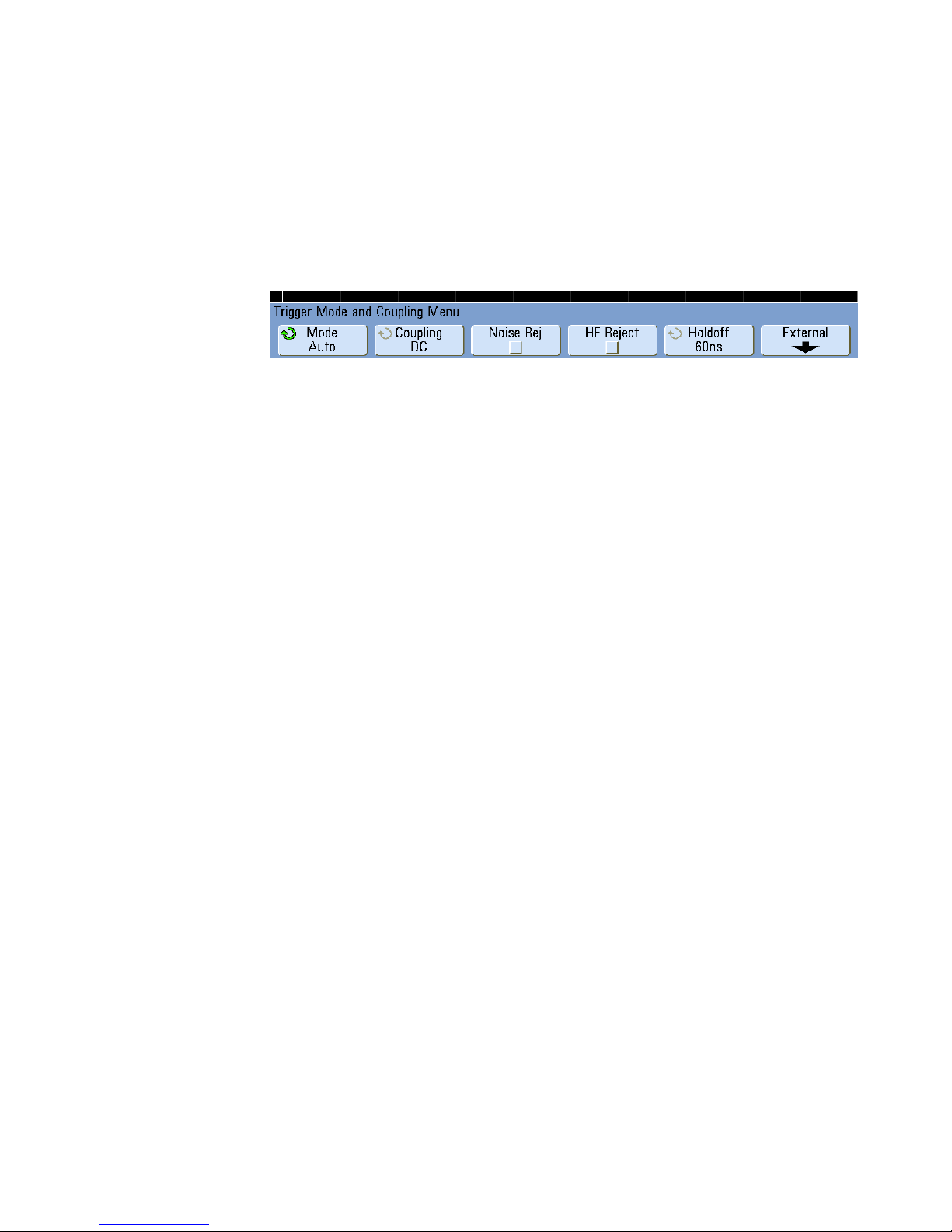
4 Triggering
2-channel
models only
Trigger Mode and Coupling Menu
• Press the [Mode/Coupling] key in the Trigger section of the front panel.
Auto and Normal Trigger modes
Choosing Auto Trigger Mode or Normal Trigger Mode
If you press [Run] when the oscilloscope is in Normal trigger mode, a trigger must be
detected before an acquisition can complete. No waveform will be displayed unless the
trigger condition is met.
In Auto trigger mode, the oscilloscope automatically triggers and captures waveforms
when you press [Run].
In many cases, a triggered display is not needed to check signal levels or activity. For
these applications, use Auto trigger mode (which is the default setting). If you only want
to acquire specific events as specified by the trigger settings, use Normal trigger mode.
In some cases, such as when triggering on a slow serial signal (for example, I
CAN, LIN, etc.) it may be necessary to select the Normal trigger mode to stabilize the
display by preventing the oscilloscope from Auto-triggering.
You can select the trigger mode by pressing the [Mode/Coupling] key, then the Mode
softkey.
1 Press the [Mode/Coupling] key.
2 Press the Mode softkey, then select Normal or Auto.
• Normal — displays a waveform when the trigger conditions are met, otherwise the
oscilloscope does not trigger and the display is not updated.
• Auto — is the same as Normal mode, except it forces the oscilloscope to trigger if
the trigger conditions are not met.
84 InfiniiVision Oscilloscopes User’s Guide
2
C, SPI,
Page 85

Triggering 4
Auto Mode
Use the auto trigger modes for signals other than low-repetitive-rate signals and for
unknown signal levels. To display a DC signal, you must use auto trigger mode since there
are no edges on which to trigger.
When you select [Run], the oscilloscope operates by first filling the pre-trigger buffer. It
starts searching for a trigger after the pre-trigger buffer is filled, and continues to flow
data through this buffer while it searches for the trigger. While searching for the trigger,
the oscilloscope overflows the pre-trigger buffer; the first data put into the buffer is the
first pushed out (FIFO). When a trigger is found, the pre-trigger buffer will contain the
events that occurred just before the trigger. If no trigger is found, the oscilloscope
generates a trigger and displays the data as though a trigger had occurred. In this case,
the background of the Auto indicator at the top of the display will flash, and the Auto
indicator will change to Auto? indicating that the oscilloscope is forcing triggers.
When you press the [Single] key, the oscilloscope will fill pre-trigger buffer memory, and
continue flowing data through the pre-trigger buffer until the auto trigger overrides the
searching and forces a trigger. At the end of the trace, the oscilloscope will stop and
display the results.
Normal Mode
Use Normal trigger mode for low repetitive-rate signals or when Auto trigger is not
required.
In Normal mode the oscilloscope must fill the pre-trigger buffer with data before it will
begin searching for a trigger event. The trigger mode indicator on the status line flashes
Trig’d? to indicate the oscilloscope is filling the pre-trigger buffer. While searching for the
trigger, the oscilloscope overflows the pre-trigger buffer; the first data put into the buffer
is the first pushed out (FIFO).
When the trigger event is found, the oscilloscope will fill the post-trigger buffer and
display the acquisition memory. The trigger mode indicator on the status line indicates
Trig’d (not flashing). If the acquisition was initiated by [Run/Stop], the process repeats.
If the acquisition was initiated by pressing [Single], then the acquisition stops and you
can Pan and Zoom the waveform.
In either Auto or Normal mode, the trigger may be missed completely under certain
conditions. This is because the oscilloscope will not recognize a trigger event until the
pre-trigger buffer is full. Suppose you set the Time/Div knob to a slow sweep speed, such
as 500 ms/div. If the trigger condition occurs before the oscilloscope has filled the
InfiniiVision Oscilloscopes User’s Guide 85
Page 86

4 Triggering
T
pre-trigger buffer, the trigger will not be found. If you use Normal mode and wait for the
trigger condition indicator to flash before causing the action in the circuit, the
oscilloscope will always find the trigger condition.
Some measurements you want to make will require you to take some action in the device
under test to cause the trigger event. Usually, these are single-shot acquisitions, where
you will use the [Single] key.
Trigger Level Adjustment
You can adjust the trigger level for a selected analog channel by turning the Trigger Level
knob. The position of the trigger level for the analog channel is indicated by the trigger
level icon (if the analog channel is on) at the far left side of the display when DC
coupling is selected. The value of the analog channel trigger level is displayed in the
upper-right corner of the display.
The trigger level for a selected digital channel is set using the threshold menu in the
Digital Channel Menu. Press the [D15-D0] key on the front panel, then press the
Thresholds softkey to set the threshold level (TTL, CMOS, ECL, or user defined) for the
selected digital channel group. The threshold value is displayed in the upper-right corner
of the display.
The line trigger level is not adjustable. This trigger is synchronized with the power line
supplied to the oscilloscope.
86 InfiniiVision Oscilloscopes User’s Guide
Page 87

Trigger Coupling
Triggering 4
1 Press the [Mode/Coupling] key.
2 Press the Coupling softkey, then select DC, AC, or LF Reject coupling.
• DC coupling allows DC and AC signals into the trigger path.
• AC coupling places a 10 Hz high-pass filter in the trigger path removing any DC
offset voltage from the trigger waveform. The high-pass filter in the External Trigger
input path is 3.5 Hz for all models. Use AC coupling to get a stable edge trigger
when your waveform has a large DC offset.
• LF (low frequency) Reject coupling places a 50 kHz high-pass filter in series with
the trigger waveform. Low frequency reject removes any unwanted low frequency
components from a trigger waveform, such as power line frequencies, that can
interfere with proper triggering. Use this coupling to get a stable edge trigger when
your waveform has low frequency noise.
• TV coupling is normally grayed-out, but is automatically selected when TV trigger is
enabled in the Trigger More Menu.
Note that Trigger Coupling is independent of Channel Coupling. To change Channel
Coupling see page 61.
Trigger Noise Rejection
If the signal you are probing is noisy, you can set up the oscilloscope to reduce the noise
on the displayed waveform. First, stabilize the displayed waveform by removing the noise
from the trigger path. Second, reduce the noise on the displayed waveform.
1 Connect a signal to the oscilloscope and obtain a stable display.
2 Remove the noise from the trigger path by turning on high-frequency rejection (HF
Reject), low-frequency rejection (LF Reject), or Noise Rejection.
3 Use Averaging Mode to reduce noise on the displayed waveform.
InfiniiVision Oscilloscopes User’s Guide 87
Page 88

4 Triggering
-3 dB
Pass
Band
0 dB
DC 50 kHz
HF Reject
HF Reject adds a 50 kHz low-pass filter in the trigger path to remove high frequency
components from the trigger waveform. You can use HF Reject to remove high-frequency
noise, such as AM or FM broadcast stations or noise from fast system clocks, from the
trigger path.
1 Press [Mode/Coupling]&HF Reject.
88 InfiniiVision Oscilloscopes User’s Guide
Page 89
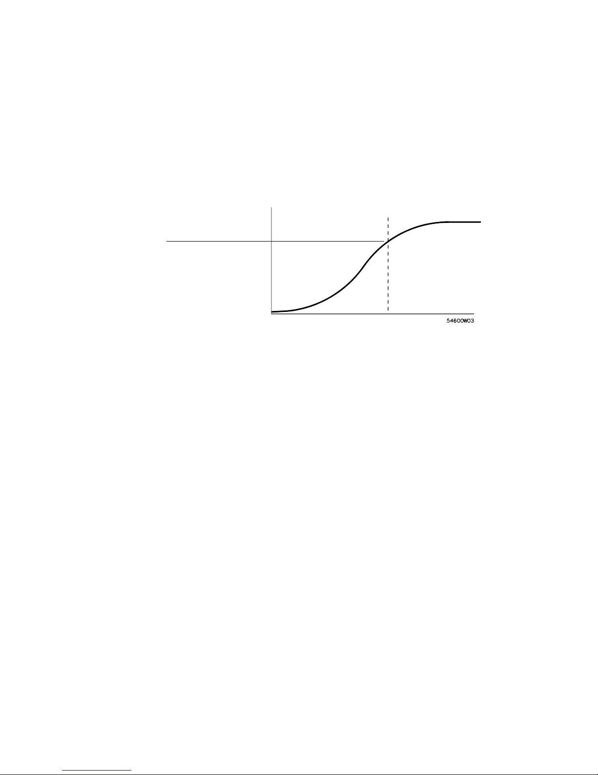
Triggering 4
3 dB down point
Pass
Band
0 dB
50 kHz
DC
LF Reject
Low-frequency reject (LF reject) adds a high-pass filter with the 3-dB point at 50 kHz. LF
reject removes low-frequency signals, such as power line noise, from the trigger path.
1 Press [Mode/Coupling]&Coupling&LF Reject.
Noise Rejection
Noise Rej adds additional hysteresis to the trigger circuitry. By increasing the trigger
hysteresis band, you reduce the possibility of triggering on noise. However, this also
decreases the trigger sensitivity so that a slightly larger signal is required to trigger the
oscilloscope.
1 Press [Mode/Coupling]&HF Reject.
InfiniiVision Oscilloscopes User’s Guide 89
Page 90

4 Triggering
Scope triggers here
Holdoff
200 ns 600 ns
Trigger Holdoff
Trigger Holdoff Operating Hints
Holdoff keeps a trigger from occurring until after a certain amount of time has passed
since the last trigger. This feature is valuable when a waveform crosses the trigger level
multiple times during one period of the waveform.
Without holdoff, the oscilloscope could trigger on each of the crossings, producing a
confusing waveform. With holdoff set correctly, the oscilloscope always triggers on the
same crossing. The correct holdoff setting is typically slightly less than one period. Set
the holdoff to this time to generate a unique trigger point. This action works even though
many waveform periods pass between triggers, because the holdoff circuit operates on
the input signal continuously.
Changing the time base settings does not affect the holdoff number. In contrast, the
holdoff in analog oscilloscopes is a function of the time base setting, making it necessary
to readjust the holdoff each time you change the time base setting.
With Agilent’s MegaZoom technology, you can press [Stop], then pan and zoom through
the data to find where it repeats. Measure this time using the cursors, then set the
holdoff.
To set holdoff
1 Press the [Mode/Coupling] key; then press the Holdoff softkey.
2 Turn the Entry knob to increase or decrease the trigger holdoff time shown.
Holdoff sets the amount of time that the oscilloscope waits before re-arming the trigger
circuitry. Use Holdoff to stabilize the display of complex waveforms.
To get a stable trigger on the pulse burst shown below, set the holdoff time to be >200 ns
but <600 ns.
90 InfiniiVision Oscilloscopes User’s Guide
Page 91

Triggering 4
By setting the Holdoff, you can synchronize triggers. The oscilloscope will trigger on one
edge of the waveform, and ignore further edges until the holdoff time expires. The
oscilloscope will then re-arm the trigger circuit to search for the next edge trigger. This
allows the oscilloscope to trigger on a repeating pattern in a waveform.
InfiniiVision Oscilloscopes User’s Guide 91
Page 92

4 Triggering
External Trigger Input
The External Trigger input can be used as a source in several of the trigger types.
On 2-channel oscilloscopes, the external trigger BNC input is on the front panel and is
labeled Ext Trigger.
On 4-channel oscilloscopes, the external trigger BNC input is on the rear panel and is
labeled Ext Trig.
2-Channel Oscilloscope External Trigger Input
External Trigger Probe Settings
You can set external trigger probe parameters as described below.
1 Press the [Mode/Coupling] key in the Trigger section of the front panel.
2 Press the External softkey to display the External Trigger Menu.
Probe Attenuation Turn the Entry knob to set the attenuation factor displayed in the
Probe softkey for the connected probe. The attenuation factor can be set from 0.1:1 to
1000:1 in a 1-2-5 sequence.
When you connect an AutoProbe self-sensing probe, the oscilloscope will automatically
configure your probe to the correct attenuation factor.
The probe correction factor must be set properly for measurements to be made correctly.
Range The input voltage range can be set to 1.0 Volts or 8.0 Volts. When in current
mode, the range is fixed at 1.0 Amps. Range is automatically scaled according to the
probe’s attenuation factor.
92 InfiniiVision Oscilloscopes User’s Guide
Page 93

Triggering 4
CAUTION
Maximum voltage at 2-channel oscilloscope external trigger input:
CAT I 300 Vrms, 400 Vpk; transient overvoltage 1.6 kVpk
CAT II 100 Vrms, 400 Vpk
50 input: 5 Vrms
Input protection is enabled in 50 mode and the 50 load will disconnect if greater
than 5 Vrms is detected. However the inputs could still be damaged, depending on
the time constant of the signal. The 50 input protection only functions when the
oscilloscope is powered on.
1 M ohm input, 100 MHz models:
For steady-state sinusoidal waveforms derate at 20 dB/decade above 200 kHz to a
minimum of 10 Vpk
1 M ohm input, 350 MHz, 500 MHz, 1 GHz models:
For steady-state sinusoidal waveforms derate at 20 dB/decade above 57 kHz to a
minimum of 5 Vpk
With N2863A 10:1 probe: CAT I 600 V, CAT II 300 V (DC + peak AC)
With 10073C or 10074C 10:1 probe: CAT I 500 Vpk, CAT II 400 Vpk
Input Impedance The 2-channel oscilloscopes have selectable external trigger input
impedance. The impedance can be set to either 1M Ohm or 50 Ohm by pressing the
Imped softkey.
•50Ohm — matches 50-ohm cables commonly used in making high frequency
measurements. This impedance matching gives you the most accurate measurements
since reflections are minimized along the signal path.
•1MOhm — is for use with many passive probes and for general-purpose
measurements. The higher impedance minimizes the loading effect of the
oscilloscope on the device under test.
Probe Units Press the Units softkey to select the proper measurement unit for the
connected probe. Select Volts for a voltage probe and select Amps for a current probe.
Measurement results, channel sensitivity, and trigger level will reflect the measurement
units you have selected.
InfiniiVision Oscilloscopes User’s Guide 93
Page 94

4 Triggering
CAUTION
4-Channel Oscilloscope External Trigger Input
Input Impedance The external trigger input impedance for the 4-channel oscilloscope
is approximately 2.14 k.
Input Voltage The input voltage sensitivity is 500 mV, from DC to 500 MHz. The input
voltage range is ±15 V.
Maximum voltage at 4-channel oscilloscope external trigger input: 15 Vrms. Do not
exceed 15 Vrms at rear panel External Trigger input or damage to the oscilloscope
may occur.
There are no range or units settings for the External Trigger input of the 4-channel
oscilloscope.
94 InfiniiVision Oscilloscopes User’s Guide
Page 95

Trigger Output
Triggers
Source Frequency
Triggering 4
You can select one of the following signals to be output at the TRIG OUT connector on the
rear panel of the oscilloscope:
• Triggers
• Source frequency
• Source frequency/8
• Mask test pass/fail (see “Mask Test Trigger Output” on page 342.)
This is the default selection. In this mode, a rising edge is output each time the
oscilloscope triggers. This rising edge is delayed 17 ns from the oscilloscope’s trigger
point. The output level is 0-5 V into an open circuit, and 0-2.5 V into 50 .
This mode is only available when the oscilloscope is set to positive or negative edge
trigger on a front-panel source (analog channel or the external input of a 2-channel
oscilloscope). In this mode, the TRIG OUT BNC is connected to the output of the trigger
comparator. The output level is 0-580 mV into an open circuit, and 0-290 mV into 50 .
The maximum frequency output is 350 MHz due to the bandwidth limitation of the TRIG
OUT BNC amplifier. This selection is useful for driving an external frequency counter.
Source Frequency/8
This selection produces the same signal as described in Source frequency except the
output frequency is one-eighth of the trigger comparator output frequency. This mode is
useful when your input signal is faster than 350 MHz.
The Trigger Out connector also provides the User Cal signal. See “User Calibration” on
page 394.
InfiniiVision Oscilloscopes User’s Guide 95
Page 96

4 Triggering
Trigger Types
The oscilloscope lets you synchronize the display to the actions of the device under test
by defining a trigger condition. You can use any input channel or the External Trigger
Input BNC as the source for most trigger types.
MegaZoom Technology Simplifies Triggering
With the built-in MegaZoom technology, you can simply AutoScale the waveforms, then stop the
oscilloscope to capture a waveform. You can then pan and zoom through the data using the
Horizontal and Vertical knobs to find a stable trigger point. AutoScale often produces a triggered
display.
The following trigger types are presented in this chapter:
• CAN Trigger 98
• Duration Trigger 102
• Edge Trigger 105
• FlexRay Setup and Triggering 107
• Glitch or Narrow Pulse Capture 112
• I2C Trigger 115
• I2S Trigger 121
• LIN Trigger 128
• MIL-STD 1553 Setup and Triggering 131
• Nth Edge Burst Trigger 135
• Pattern Trigger 137
• Pulse Width Trigger 140
• Sequence Trigger 143
• SPI Trigger 150
• TV Trigger 156
• UART/RS232 Trigger 166
• USB Trigger 170
96 InfiniiVision Oscilloscopes User’s Guide
Page 97

Triggering 4
Changes to the trigger specification are applied when you make them. If the oscilloscope
is stopped when you change a trigger specification, the oscilloscope will use the new
specification when you press [Run/Stop] or [Single]. If the oscilloscope is running when
you change a triggering specification, it uses the new trigger definition when it starts the
next acquisition.
InfiniiVision Oscilloscopes User’s Guide 97
Page 98
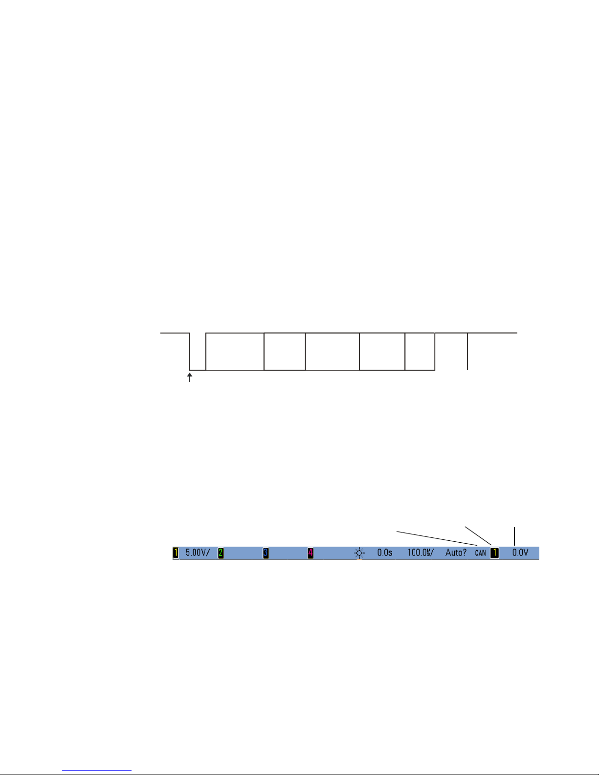
4 Triggering
Arbitration
Field
Control
Field
CRC
Field
ACK
Field
Data
Field
Bus
Idle
Inter-
mission
EOF
SOF edge
Trigger level
or threshold
Currently selected
signal source
CAN trigger
CAN Trigger
The Controller Area Network (CAN) trigger allows triggering on CAN version 2.0A and
2.0B signals. Setup consists of connecting the oscilloscope to a CAN signal, using the
Signals Menu to specify the signal source, baud rate, and sample point, and using the
Settings Menu to specify the event to trigger upon.
If the AMS license is not installed on the oscilloscope, you can still trigger on the Start of
Frame (SOF) bit of a CAN data frame. If the N5424A CAN/LIN Automotive Triggering and
Decode option (license AMS) is installed on your oscilloscope, the following additional
CAN trigger types will also be available: Remote Frame ID (RTR), Data Frame ID (
RTR),
~
Remote or Data Frame ID, Data Frame ID and Data, Error Frame, All Errors, Acknowledge
Error, and Overload Frame.
A CAN message frame in CAN_L signal type is shown below:
1 Press [Save/Recall]&Default Setup.
2 Press the [Label] key to switch labels on.
3 Turn on the analog or digital channel that you will be using for the CAN signal.
4 Press the [More] key in the Trigger section of the front panel, rotate the Entry knob
until CAN is displayed in the Trigger softkey.
98 InfiniiVision Oscilloscopes User’s Guide
Page 99

Triggering 4
Trigger
condition
Signals
Menu
Return to
previous menu
Bits
Selector
NOTE
5 Press the Settings softkey to display CAN Trigger Menu.
6 Repeatedly press and release the Trigger: softkey or rotate the Entry knob to select the
trigger condition.
• SOF - Start of Frame — The oscilloscope triggers at the start of a frame.
• Remote Frame ID (RTR) — The oscilloscope triggers on remote frames with the
specified ID. Press the Bits softkey to select the ID.
For details about using the CAN Bits Menu softkeys, press and hold the softkey in
question to display the built-in help.
• Data Frame ID (~RTR) - The oscilloscope will trigger on data frames matching the
specified ID. Press the Bits softkey to select the ID.
• Remote or Data Frame ID - The oscilloscope will trigger on remote or data frames
matching the specified ID. Press the Bits softkey to select the ID.
• Data Frame ID and Data - The oscilloscope will trigger on data frames matching
the specified ID and data. Press the Bits softkey to select the ID and set up the
number of data bytes and values.
• Error Frame - The oscilloscope will trigger on CAN active error frames.
• All Errors - The oscilloscope will trigger when any form error or active error is
encountered.
• Acknowledge Error - The oscilloscope will trigger when the acknowledge bit is
recessive (high).
• Overload Frame - The oscilloscope will trigger on CAN overload frames.
InfiniiVision Oscilloscopes User’s Guide 99
Page 100

4 Triggering
Baud Rate
Signals
source
Sample
Point
Return to
previous menu
Userdefined
Baud Rate
CAN Signal
Selection
7 Press the Signals softkey to enter the CAN Signals Menu.
8 Press the Source softkey to select the channel connected to the CAN signal line.
As you repeatedly press the Source softkey (or rotate the Entry knob), the CAN label
for the source channel is automatically set and the channel you select is shown in the
upper-right corner of the display next to “CAN”.
If you have connected one of the oscilloscope’s analog source channels to the CAN
signal: Adjust the trigger level for the selected analog channel to the middle of the
waveform by turning the Trigger Level knob.
If you have connected one of the oscilloscope’s digital source channels to the CAN
signal (this applies to MSO model oscilloscopes only): Press the [D15-D0] key and
select Thresholds to set an appropriate threshold level for digital channels.
The value of the trigger level or digital threshold is displayed in the upper-right corner
of the display.
9 Press the Signal softkey and select the type and polarity of the CAN signal. This also
automatically sets the channel label for the source channel.
• CAN_H — The actual CAN_H differential bus
Dominant low signals:
• CAN_L — The actual CAN_L differential bus signal
• Rx — The Receive signal from the CAN bus transceiver
• Tx — The Transmit signal from the CAN bus transceiver
• Differential — The CAN differential bus signals connected to an analog source
channel using a differential probe. Connect the probe’s positive lead to the
dominant-low CAN signal (CAN_L) and connect the negative lead to the
dominant-high CAN signal (CAN_H).
10 Repeatedly press and release the Baud softkey to set the CAN signal baud rate to
match your CAN bus signal.
100 InfiniiVision Oscilloscopes User’s Guide
 Loading...