

Page 1
Agilent E2251A
M-Module Carrier
Installation and Wiring Manual
Agilent 75000 Series C
Where to Find it - Online and Printed Information:
System installation (hardware/software)............VXIbus Configuration Guide*
Installing M-Modules onto M-Module Carrier..This Manual (Service-Trained Personnel only)
Installing M-Module Carrier into
VXI Mainframe..................................................This Manual (Service-Trained Personnel only)
M-Module configuration and wiring..................M-Module Hardware Manual
M-Module programming example (SCPI).........Agilent E2251A M-Module User’s Manual
M-Module programming example
(register-based)...................................................Agilent E2251A M-Module User’s Manual
VXIplug&play programming ............................VXIplug&play Online Help
VXIplug&play example programs .....................VXIplug&play Online Help
VXIplug&play function reference......................VXIplug&play Online Help
Soft Front Panel information.............. ................VXIplug&play Online Help
VISA language information. ...................... .... .....VISA User's Guide
*Supplied with Agilent Comm and Modules, Embedded Controllers, and VXLink.
*E2251-90002*
Manual Part Number: E2251-90002
Printed in Malaysia E0206
Page 2

Page 3

Contents
Agilent E2251A M-Module Carrier Installation and Wiring
Manual
AGILENT TECHNOLOGIES WARRANTY STATEMENT.....................................3
Safety Symbols.............................................................................................................4
WARNINGS.................................................................................................................4
WARNINGS (contd.) ...................................................................................................5
Declaration of Conformity............................................................................................6
M-Module Installation
Step 1. Remove the Carrier Shields............................................................................10
Step 2. Determine M-Module Layout ........................................................................11
Step 3. Set the Logical Address for each M-Module..................................................12
Guidelines for Determining Logical Addresses ..................................................12
Unused Slots on the Carrier ................................................ ................................12
Setting the Addresses ..........................................................................................13
Step 4. Install M-Modules onto the Carrier ...............................................................14
Step 5. Connect Field Wiring to Slot M4 & M5 M-Modules.....................................15
Step 6. Reattach the Carrier Shields...........................................................................16
Step 7. Install Carrier into C-Size VXI Mainframe....................................................17
Step 8. Connect Field Wiring to Front M-Modules....................................................18
Step 9. Installation / Operational Verification............................................................19
You Are Done .....................................................................................................19
Removing M-Modules from the Carrier.....................................................................20
(Edition 2)
M-Module Field Wiring Information
Assembling the M-Module Field Wiring Connector..................................................21
E2259A Double-Wide Breadboard M-Module Wiring Information.......................... 24
E2261A Quad RS-232 Interface Wiring Information.................................................26
E2270A 16-Channel Form A Switch Wiring Information .........................................28
E2271A 4x4 Matrix Switch Wiring Information........................................................29
E2272A Dual 8-to-1/Single 16-to-1 Relay Multiplexer Wiring Information............. 30
Configuring the E2272A .....................................................................................30
E2273A 8-Channel Form C Switch Wiring Information ........................................32
E2274A 4-Channel Power Relay Wiring Information ...............................................33
E2290A 16-Bit Digital I/O Wiring Information.........................................................34
E2291A 16-Channel Isolated Digital Output Wiring Information.............................35
Contents 1
Page 4

2 Contents
Page 5

Certification
Agilent Technologies, Inc. certifies that this product met its published specifications at the time of shipment from the factory. Agilent
Technologies further certifies that its calibration measurements are traceable to the United States National Institute of Standards and
Technology (formerly National Bureau of Standards), to the extent allowed by that organization's calibration facility, and to the
calibration facilities of other International Standards Organization members .
AGILENT TECHNOLOGIES WARRANTY STATEMENT
AGILENT PRODUCT: B-size and C-s i z e VX I modules DURATION OF WARRANTY: 1 year
1. Agilent warrants Agilent hardware, accessories and supplies against defects in material s and workmanship for the period specified
above. If Agilent receives notice of such defects during the warranty period, Agilent will, at its option, either repair or replace products
which prove to be def e ctive. Replacement products may be either new or like-new.
2. Agilent warrants that Agilent software will not fail to execute its programming instructions, for the period specified above, due to
defects in material and workmanship when properly installed and used. If Agilent receives notice of such defects during the warranty
period, Agilent will replace software media which does no t execu te its programm in g instr uctio ns du e to such defe cts.
3. Agilent does not warrant that the operation o f Agilent products will be interrup ted or error free. If Agilent is unable, within a reasonable
time, to repair or replace any product to a con dition as warrant ed, custome r will be entit led to a ref und of the pu rchase pri ce upon prompt
return of the product.
4. Agilent products may contain remanufactured parts equivalent to new in performance or may have been subject to incidental use.
5. The warrant y peri od begi ns on the d ate of deliver y or on the date o f install ation if install ed by A gilent. If custom er sch edul es or dela ys
Agilent installation more than 30 days after delivery, warranty begins on the 31st day from delivery.
6. Warranty does not apply to defects resulting from (a) improper or inadequate maintenance or calibration, (b) software, interfacing, parts
or supplies not supplied by Agilent, (c) unauthorized modification or misuse, (d) operation outside of the published environmental
specifications for the product, or (e) improper site preparation or maintenance.
7. TO THE EXTENT ALLOWED BY LOCAL LAW, THE ABOVE WARRANTIES ARE EXCLUSIVE AND NO OTHER
WARRANTY OR CONDITION, WHETHER WRITTEN OR ORAL, IS EXPRESSED OR IMPLIED AND AGILENT
SPECIFICALLY DISCLAIMS ANY IMPLIED WARRANTY OR CONDITIONS OF MERCHANTABILITY, SATISFACTORY
QUALITY, AND FITNESS FOR A PARTICULAR PURPOSE.
8. Agilent will be liable for damage to tangib le property per in cident up to the gre ater of $300,000 or the actual amoun t paid for t he pr oduct
that is the subject of the claim, and for damages for bodily injury or death, to the extent that all such damages are determined by a court
of competent jurisdiction to have been directl y caused by a defective Agilent product.
9. TO THE EXTENT ALLOWED BY LOCAL LAW, THE REMEDIES IN THIS WARRANTY STATEMENT ARE CUSTOMER’S
SOLE AND EXLUSIVE REMEDIES. EXCEPT AS INDICATED ABOVE, IN NO E VENT WILL AGILENT OR ITS SUPPL IERS BE
LIABLE FOR LOSS OF DATA OR FOR DIRECT, SP ECIAL, INCIDENTAL, CONSEQUENTIAL (INCLUDING LOST PROFIT OR
DATA), OR OTHER DAMAGE, WHETHER BASED IN CONTRACT, TORT, OR OTHERWISE.
FOR CONSUMER TRANSACTIONS IN AUSTRALIA AND NEW ZEALAND: THE WARRANTY TERMS CONTAINED IN THIS
STATEMENT, EXCEPT TO THE EXTENT LAWFULLY PERMITTED, DO NOT EXCLUDE, REST RICT OR MODIFY AND ARE
IN ADDITION TO THE MANDATORY STATUTORY RIGHTS APPLICABLE TO THE SALE OF THIS PRODUCT TO YOU.
U.S. Government Restricted Rights
The Software and Documentation have been developed entirely at private expense. They are delivered and licensed as "commercial
computer software" as defined in DFARS 252.227- 7013 (Oct 1988), DFARS 252.211-7015 (May 1991) or DFARS 252.227-7014 (Jun
1995), as a "commerci al item" as defined in FAR 2.101(a), or as "Restricted computer software" as defined in FAR 52.227-19 (Jun
1987)(or any equivalent agency regulation or contract clause), whichever is applicable. You have only those rights provided for such
Software and Documentation by the applicable FAR or DFARS clause or the standard software agreement for the product involved.
Agilent E2251A M-Module Carrier Installation Manual
Copyright © 1998-2006 Agilent Technologies, Inc. All Rights Reserved.
Edition 1
3
Page 6
or
Documentation History
All Editions and Updates of t his manu al and th eir creati on da te are list ed belo w. The first Edition of the m anual is Editi on 1. T he Ed ition
number increments by 1 whenever the manual is revised. Upd a tes, which are issued between Editions, contain replacement pages to
correct or add additional information to the current Edition of the manual. Whenever a new Edition is created, it will contain all of the
Update information for the previous E dition. Each new Edition or Update also inc ludes a revised co py of this doc umentation hi story page.
Edition 1 . . . . . . . . . . . . . . . . . . . . . . . . . . . . . . . . . . . . . . . . . . . . . . . .June 1997
Edition 2 . . . . . . . . . . . . . . . . . . . . . . . . . . . . . . . . . . . . . . . . . . . . February 1998
Safety Symbols
Instruction manual symbol affixed to
Instruction manual symbol affixed to
product. Indicates that the user must refer to
product. Indicates that the user must refer to
the manual for specific WARNING or
the manual for specific WARNING or
CAUTION information to avoid personal
CAUTION information to avoid personal
injury or damage to the product.
injury or damage to the product.
Indicates the field wiring te rminal th at must
be connected to eart h ground before
operating the equipment — protects against
electrical shock in case of fault.
WARNING
Alternating current (AC)
Direct current (DC).
Indicates hazardous voltages.
Calls attention to a procedure, practice, or
condition that could cause bodily injury or
death.
Frame or chassis ground terminal—typ ically
connects to the equipment's metal frame.
CAUTION
Calls attention to a procedure, practice, or
condition that coul d possibly cause damage to
equipment or permanent loss of data.
WARNINGS
The following gener al safety precautions must b e observed during all phases of operation, service, and repair of this product. Failure to
comply with these precautions or with specific warnings elsewhere in this manual violates safety standards of design, manufacture, and
intended use of the product. Hewlett-Packar d Company assumes no liabilit y for the customer's failu re to comply with these requi rements.
Ground the equipment: For Safety Class 1 equipment (equipment having a protective earth terminal), an uninterruptible safety earth
ground must be provided from the mains power source to the product input wiring terminals or supplied power cable.
DO NOT operate the product in an explosive atmosphere or in the presence of flammable gases or fumes.
For continued protection against fire, replace the line fuse(s) only with fu se(s) of the same voltage and curren t ratin g and type. DO NOT
use repaired fuses or short-circuited fuse holders.
Keep away from live circuits: Operating personnel must not remove equipment covers or shields. Procedures involving the removal of
covers or shields are for use by service-trained personnel only. Under certain conditions, dangerous voltages may exist even with the
equipment sw itche d off. To av oid da ngerou s elec trical s hock , DO N OT per form pr ocedur es inv olving cover or shi eld removal unles s you
are qualified to do so.
DO NOT operate damaged equipment: Whenever it is possible that the safety protection features built into this product have been
impaired, either through physical damage, excessive moisture, or any other reason, REMOVE POWER and do not use the product until
safe operation can be verified by service-trained personnel. If necessary, return the product to an Agilent Technologies Sales and Service
Office for service and repair to ensure that safety features are maintained.
DO NOT service or adjust alone: Do not attempt internal service or adjustment unless another person, capable of rendering first aid and
resuscitation, is present.
DO NOT substitute parts or modify equipment: Because of th e dang er of int roduc ing ad ditiona l hazar ds, do not ins tall su bstitut e parts
or perform any unauthorized modification to the product. Return the product to an Agilent Technologies Sales and Service Office for
service and repair to ensure that safety features are maintained.
4
Page 7

WARNINGS (contd.)
In a cleanroom environment, some switch modules (such as the E2270A, 2271A, 2273A, etc) are capable of switching voltages that could
cause bodily injury or death to an operator. Special precautions must be adhered to (discussed below) when applying voltages in excess
of 60Vdc, 30Vac rms, or 42.4 Vac peak for a continuous, complex wavef orm.
Module connectors and test signal cables conn e cted to them must be made NO N- a cce ssi ble to an op era t or w ho ha s no t been tol d
to access them: It is a supervisor’s responsibility to advise an operator that dangerous voltages exist when the operator is instructed to
access connectors and cables carry in g t hese voltages. Making cables and connectors that carry hazardous voltages inaccessible is a
protective measure keeping an operator from inadvertant or unknowing contact with these harmful voltages. Cables and connectors are
considered inaccessible if a tool (e.g., scre wdriver, wrench, socket, etc.) or a key (equipment in a locked cabinet) is required to gain access
to them. Additionally, the operator cannot have access to a conductive surface connected to any cable conductor (High, Low, or Guard).
Assure the equipment un der test has a dequate insulatio n between the cable connections and any opera tor-accessible parts (doors,
covers, panels, shields, cases, cabinets, etc.): Verify there are multiple and sufficient protective means (rated for t he v ol tages you are
applying) to assure the operator will NOT come into contact with any energized conductor even if one of the protective means fails to
work as intended. For exam ple, th e inn e r side of a case, c a bine t, d oo r, c ove r, or p ane l c an be cov e red with an in sula tin g m ate ria l as well
as routing the test cables to the module’s front panel connectors through non-conduct ive, flexible conduit such as th at used in electrical
power distribution.
5
Page 8
SA
DECLARATION OF CONFORMITY
According to ISO/IEC Guide 22 and CEN/CENELEC EN 45014
Manufacturer’s Name:
Agilent Technologies, Incorporated
Manufacturer’s Address: Measurement Product Generation Unit
815 14th ST. S.W.
Loveland, CO 80537 USA
Declares, that the product
Product Name:
Model Number:
C Size M Module Carrier
E2251A
Product Options: This declaration covers all options of the above product(s).
Conforms with the following European Directives:
The product herewith complies with the requirements of the Low Voltage Directive 73/23/EEC and the EMC Directive 89/336/EEC
and carries the CE Marking accordingly
Conforms with the following product standards:
EMC Standard
IEC 61326-1:1997+A1:1998 / EN 61326-1:1997+A1:1998
CISPR 11:1997 +A1:1997 / EN 55011:1998
IEC 61000-4-2:1995+A1:1998 / EN 61000-4-2:1995
IEC 61000-4-3:1995 / EN 61000-4-3:1995
IEC 61000-4-4:1995 / EN 61000-4-4:1995
IEC 61000-4-5:1995 / EN 61000-4-5:1995
IEC 61000-4-6:1996 / EN 61000-4-6:1996
IEC 61000-4-11:1994 / EN 61000-4-11:1994
Limit
Group 1 Class A
4kV CD, 8kV AD
3 V/m, 80-1000 MHz
0.5kV signal lines, 1kV power lines
0.5 kV line-line, 1 kV line-ground
3V, 0.15-80 MHz
I cycle, 100%
[1]
Canada: ICES-001:1998
Australia/New Zealand: AS/NZS 2064.1
Safety
IEC 61010-1:1990+A1:1992+A2:1995 / EN 61010-1:1993+A2:1995
Canada: CSA C22.2 No. 1010.1:1992
UL 3111-1:1994
IEC 950(1991) + A1(1992) + A2(1993) + A3(1994)
EN 60950(1992) + A1(1992) + A2(1993) + A3(1994)
CSA C22.2#950(1995)
UL 1950(1995)
Supplemental Information:
[1]
The product was tested in a typical configuration with Agilent Technologies test systems.
September 5, 2000
Date Name
Quality Manager
Title
Authorized EU-representative: Agilent Technologies Deutschland GmbH, Herrenberger Straβe 130, D 71034 Böblingen, Germany
For further information, please contact your local Agilent Technologies sales office, agent or distributor.
Revision: A.03 Issue Date: 09/05/00
Page 9

Page 10

Page 11

M-Module Installation
This manual provides the following information:
•Installing M-Modules in the E2251A Carrier including:
-- Setting Logical Addresses
-- Attaching Field Wiring and Strain Relief
-- Installing RFI Dress Panels
•Installing the E2251A Carrier in a VXIbus Mainframe
• M-Module installation verification.
•Removing M-Modules from the Carrier.
For general information about the E2251A M-Module Carrier or for
M-Module programming information, refer to the E2251A M-Module
Carrier User’s Manual. For infor mation about speci fic M-Modules, refer to
that M-Module’s User’s Manual. VXIplug&play drivers, downloadable
SCPI drivers, and Soft front panels are avai la ble on t he CD ROM provided
with the Carrier and M-Modules. The E2251A does not support
MA-Modules.
WARNING SERVICE-TRAINED PERSONNEL ONLY. The information in this manual is for
service-trained personnel who are familiar with electronic cir cuit ry and are aware
of the hazards involved. To a void personal i njury or d amage to the i nstrument, do
not perform procedures in this manual or do any servicing unless you are
qualified to do so.
Caution All installation, wiring, and configuration procedures in this chapter are to be
done with power DISCONNECTED from the VXI mainframe and power
DISCONNECTED from any external wiring/cabling. To prevent equipment
damage, DISCONNECT the mainframe's power before installing any module into
the mainframe.
Caution STATIC ELECTRICITY. Static electricity is a major cause of component fai lure. To
prevent damage to the electrical components in the Carrier and the M-Modules,
observe anti-static techniques when installing or removing an M-Module from the
Carrier or installing or removing the Carrier from the VXI mainframe.
Caution Modules in Carrier slot M5 are restricted to 60Vdc, 30Vac
, or 42Vacpk.
rms
Caution Remove all packing material before installing Carrier in VXI mainframe.
9
Page 12
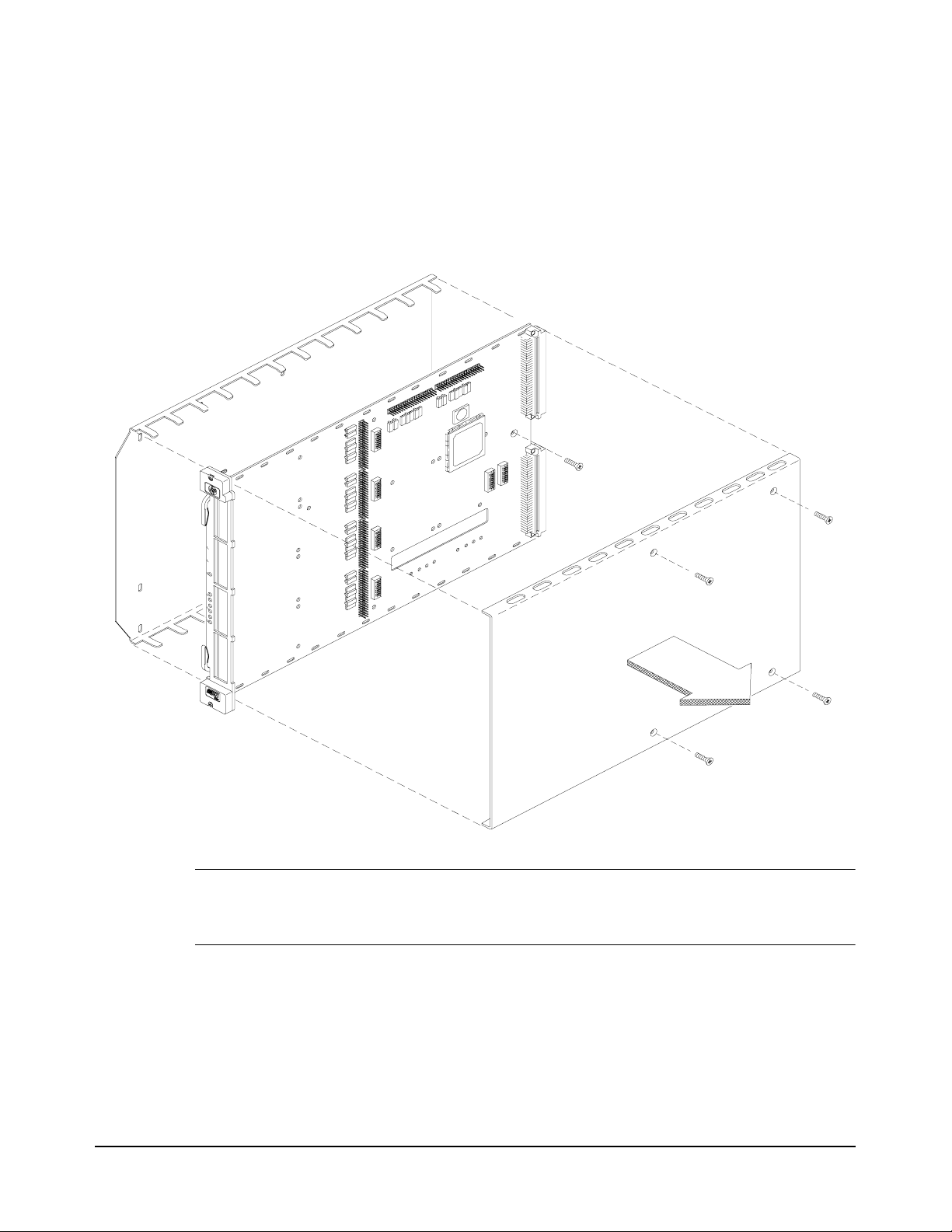
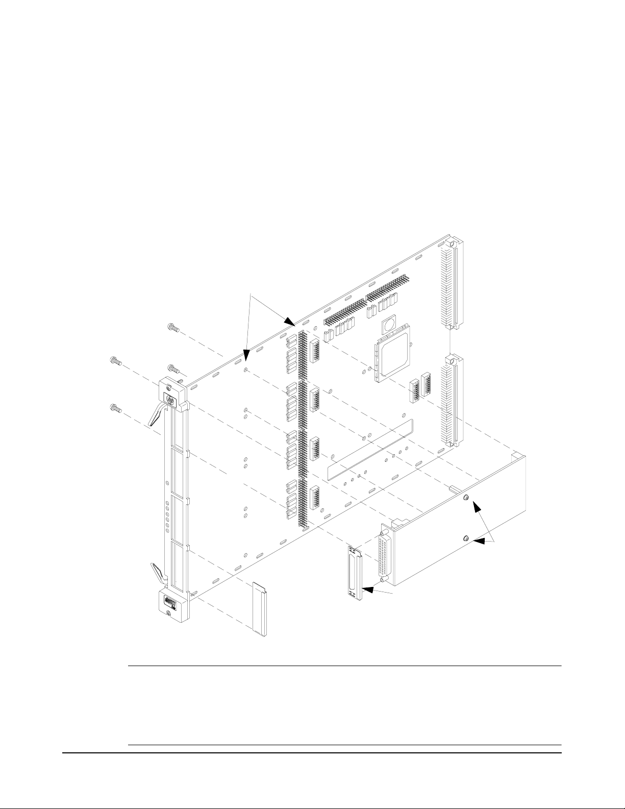
Step 1. Remove the Carrier Shields
1. Remove the four screws securing the Carrier top and bottom shield.
2. Remove the screw securing the PC board to the bottom shield.
3. Set the screws and shields aside for later re-assembly (Step 6).
M3X6
Panhead
Note Some earlier carriers did not have the scr ew sec uri ng t he PC bo ard to t he bot t om shie ld . Instead,
they had a fifth screw securing the top and bottom shields. Remove all five screws to
disassemble the Carrier.
10
Page 13

Step 2. Determine M-Module Layout
Up to 4 M-Modules
in front slots (neither
interior slot used)
Up to 5 M-Modules
(interior M-Modules
require external field
wiring)
6 M-Modules
(all slots used, interior
M-Modules do not require
external field wiring)
M
-
M
o
d
u
l
e
M
0
M
-
M
o
d
u
l
e
M
1
M
-
M
o
d
u
l
e
M
2
M
-
M
o
d
u
l
e
M
3
M
-
M
o
d
u
l
e
M
3
M
-
M
o
d
u
l
e
M
3
M
-
M
o
d
u
l
e
M
2
M
-
M
o
d
u
l
e
M
2
M
-
M
o
d
u
l
e
M
1
M
-
M
o
d
u
l
e
M
1
M
-
M
o
d
u
l
e
M
0
M-Module M4
M-Module M5
M-Module M4
M-Module M5
CAUTION: Modules in Carrier slot M5
are restricted to 60Vdc, 30Vac
rms
,
or 42Vac
pk
.
Strain Relief Plates
1. Identify the positions your M-Modules will occupy in the E2251A Carrier. The Carrier can hold up to
six M-Modules only if neither of the modules in the two interior slots (M4 & M5) require external
cabling. If one or both interior modules require external cabling, the bottom-front slot (M0) must be left
unused to accommodate the wiring; strain relief clamps are provided. The following figure shows the
common M-Module layouts.
11
Page 14

Step 3. Set the Logical Address for each M-Module
Each VXI module or M-Modul e in a VXI system must have a unique l ogical
address. The logica l address is used by the VXI resource manager t o identify
instruments. When t he logica l addres s of a module is set to a direct multiple
of 8 (such as 8, 16, 24, ... 256), that module is considered an “instrument”.
An instrument's seconda ry address (used to pro gram the module from GPIB)
is derived by dividing the instrument logical address by 8. For example, a
logical address of 24 is a secondary address of 03.
Guidelines for
Determining Logical
Addresses
Note Multiple-module Scanning Voltmeter or Switchbox instruments are not
Unused Slot s on th e
Carrier
The E2251A comes from the factory with the M-Module logical address
switches set to 0.
instructs the Carrier to ignore that slot and the Carrier does not report it to
the VXI system resource manager.
You must
in the E2251A Carrier.
If you are using an E1406 Command Module set M-Modul e add resses to a
multiple of 8 (i.e., 8, 16, 24, 32, . . . 256). Do not set any M-Modul e logical
address to the same value as any ot her M- Module or any o ther VXI mod ule
in the system. You can use up to 31 M- Modules (up to se ven Carr iers ) with
an E1406 Command Module or 255 M-Modules (up to 51 Carriers) with
embedded controllers, VXLink, or MXIbus controllers.
supported with M-Modules on the E2251A Carrier. Multiple-module
instruments can only be created using standard B- or C-size VXI modules.
Unused slots on the E2251A Carri er should hav e their lo gical addr ess set to
0 (zero). With the logical address set to 0, the Carrier disables the circuits
(interrupt, reserved memory, etc.) for that slot.
1
In the E2251A M-Module Carrier, logical address 0
set the logical address switches for each M-Module installed
1. Note that in a standard VXI system, logical address 0 is reserved for the VXIbus command module / resource
manager. On the E2251A Carrier however, logical address 0 causes the Carrier to disregard that M-Module
slot.
12
Page 15

Setting the
M-Module M2
M-Module M1
M-Module M3
M-Module M0
M-Module M4
M-Module M5
Logical Address
Switch for M3
Logical Address
Switch for M0
Logical Address
Switch for M4
Logical Address
Switch for M5
Addresses
As shown below, the E2251A has six logi ca l ad dress switch banks, one f or
each M-Module slot. You must set the logical address switches for each
M-Module installed in the E2251A Carrier.
A logical address switch bank contains eight individual switches. To
determine the logical address, add together the decimal values of the
switches that are set (posi tion 1 = set, 0 = not set). For example , in the figure
below, switches 4, 5, and 6 are set, t he other switch es are not set. Th e logical
address is the su m of t he decimal values of th e set switches: 16 + 32 + 64 =
112.
13
Page 16
Step 4. Install M-Modules onto the Carrier
1. For internally-mounted M-Modules (slots M4 and M5) see Step 5, next page.
2. Install RFI Dress Panel (p.n. E2273-04301) on each of the front mounted M-Modules. Dress panels act
like a gasket and minimize RFI. Make certain the M-Module-to-Carrier connectors line up properly.
Make certain the M-Module standoffs are aligned over the screw mounting holes.
3. Secure each M-Module to the Carrier (from the back side) with four M3x5 mounting screws
(p.n. 0515-0372, with captive lock washer) supplied with M-Module. Open handles on Carrier to install
screws for slots M0 and M3 M-Modules.
4. Install blank Dress Panel (p.n. E2251-04301) over each unused front panel slot to minimize RFI.
2. Align M-Module on Carrier.
3. Secure M-Module with
four M3x6 screws.
0515-0430
Do not remove
these screws
if removing
M-Module.
1. Install E2273-04301
Dress Panel on M-Module.
4. Install E2251-04301 Blank
Dress Panels on Empty Slots.
If necessary, slightly crimp Dress Panel with pliers so it stays attached to Carrier front panel.
Caution Static Electricity. Use anti-static techniques when installing/removing M-Module.
Use care when installing M-Modules onto the carrier connectors. The Carrier and
M-Module connectors ARE NOT keyed; it is possibl e to misalign an M-Modul e and
connect it to the wrong connectors. APPLYING POWER TO A MISALIGNED
M-MODULE WILL DAMAGE OR DESTROY THE M-MODULE AND THE CARRIER.
14
Page 17
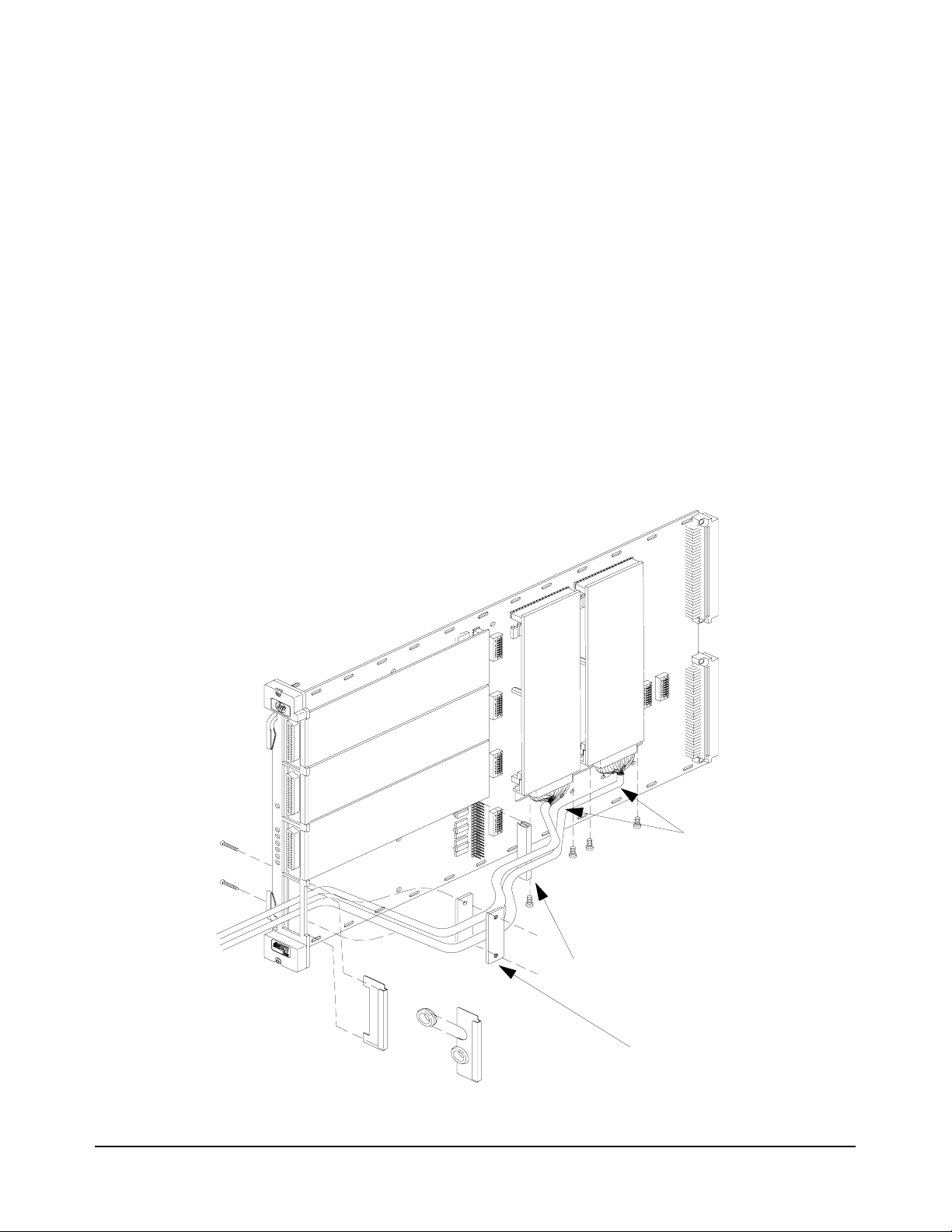
Step 5. Connect Field Wiring to Slot M4 & M5 M-Modules
If you installed M-Modules on either or both of the interior slots, the following instructions describe how to
secure the field wiring. If you did not install an M-Module in slots M4 or M5, skip this page and go to Step 6.
1. Cover the M0 2-row connector strip with provided Pin Protector/Cover (p.n. 1252-8273). This pin
protector protects the field wiring from chafing against the connector pins.
Note: Do not install the plastic cable hood (see page 21) on the field wiring connectors for the two internal
M-Modules. Do not install the RFI dress panels on the two interior M-Modules. If an RFI dress panel is
already installed on an M-Module, it must be removed. They are not needed and may interfere with
installatio n of the top shield.
2. Holes are provided in the Carrier for cable ties to secure the field wiring cables.
3. Install cable clamp plates (p.n. E 2251-01203) on top si de of PC boa rd. Secur e the cabl e clamp ( but do not
overtighten). Both clamps are required to prevent damage to PC board.
4. To minimize RFI, install a dress panel (p.n. E2251-04301) over the front panel M0 slot position. Have
the dress panel machined or punched to allow the cable to pass through. Machine the cut as small as
possible; large enoug h for the cab le and opt ional gro mmet (t o preve nt chaf ing) bu t ti ght to minimize RFI.
M3x20 Pan Head Screws
p.n. 0515-1410
2. Attach field wiring
5. Machine Dress Panel
for ribbon cable or
punch Dress Panel and add grommet for round cable.
3. Secure field wiring to
Carrier with wire ties
through holes provided
on Carrier.
to M-Modules
with 4-40 Pozidrive screws.
1. Place p.n. 1252-8273
Pin Protector over pins
to protect cable.
4. Install Cable Clamp.
Do not overtighten.
15
Page 18

Step 6. Reattach the Carrier Shields
1. Carefully place the place the PC boar d on t he bot tom Carrier shie ld. Align the mou nting holes an d secu re
with the mounting screw.
2. For modules mounted in the interior slots (M4 & M5), make certain their field wiring is not pinched.
3. Position the top shield and align the mounting holes. Install four screws securing the top and bottom
shields.
4. Attach supplied M-Module labels to the Carrier top shie ld and the RFI Dres s Panel to iden tify M-Modu le
installed in the Carrier.
M3X6
Panhead
Note Some earlier carriers did not have the scr ew sec uri ng t he PC bo ard to t he bot t om shie ld . Instead,
they had a fifth screw securing the top and bottom shields. Remove all five screws to
disassemble the Carrier.
16
Page 19

Step 7. Install Carrier into C-Size VXI Mainframe
1. Set the Carrier Extraction
2. Slide the Carrier into any slot
(except Slot 0) until the backplane
connectors touch.
3. Seat the Carrier
into the mainframe by
pushing in the extraction
levers.
4. Tighten the top and bottom screws
to secure the Carrier
to the mainframe.
Levers out.
Note: Do not push on the front
panel of the E2251A Carrier.
Doing so may bend the front panel.
WARNING To avoid possible electrical shock, make certain that power is removed from the
VXI mainframe, all field wiring, and external devices connected to the VXI
mainframe.
17
Page 20
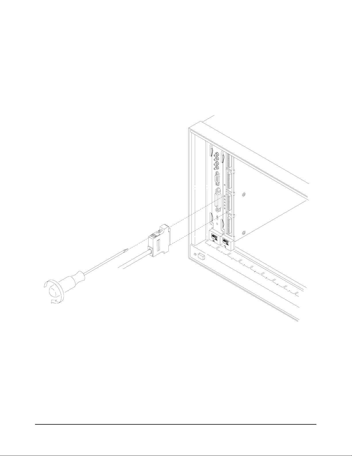
Step 8. Connect Field Wiring to Front M-Modules
1. Refer to “Assembling the M-Module Field Wiring Connec tor ” on page 21 for information on assembling
the connector and hood.
2. Attach assembled connector to M-Modules.
3. Tighten mounting screws to secure connector to the M-Module.
18
Page 21

Step 9. Installation / Operational Verification
1. Turn on the VXI mainframe and use the VXIplug&play Soft Front Panel s (SFP) to veri fy installat ion and
operation of the M-Modules. The SFPs are supplied on the CD ROM accompanying your M-Modules
and Carrier. The SFP is an MS Windows
M-Module over GP-IB or from an embedded controller. For systems with a GPIB-VXI Command
Module, such as the E1406, connect a GPIB cable between the computer’s I/O interface and the
Command Module. If the inst rument is not avail able, you can st ill run th e SFP with ‘li ve mo de’ di sable d.
Start the SFP by selectin g the LOGO a nd in str ument name in the VXIpnp program group . On li ne he lp is
available with the SFP.
You Are Done This concludes the M-Module Installation, Configuration, and Wiring
procedures for the E2251A M-Module Carrier. For Operating and
Programming information refer to the E2251A M-Module Carrier User’s
Manual. For information about specific M-Modules, refer to the respective
M-Module User’s Manual.
®
application that allows you to program an instrument or
19
Page 22
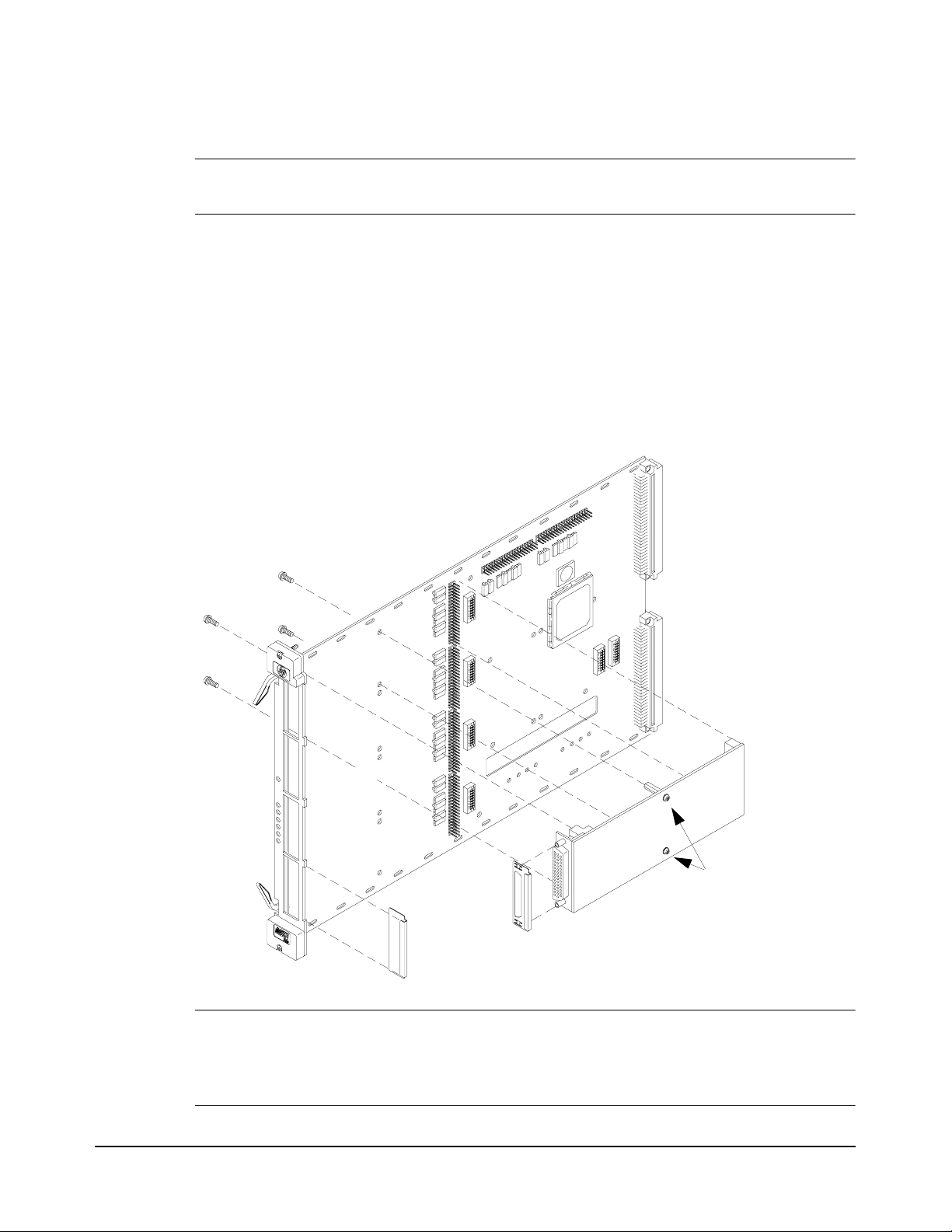
Removing M-Modules from the Carrier
WARNING To avoid possible hazardous electrical shock, remove power from the VXI
Mainframe, all field wiring, and external devices connected to the VXI mainframe.
1. Remove all field wiring connectors from the front-moun ted M-Module s of the E2251A. Refer to “Step 8.
Connect Field Wiring to Front M-Modules” on page 18 for general guidelines.
2. Remove the Carrier from the VXI Mainframe. Open the extraction levers to release the Carrier from the
mainframe. Refer to “Step 7. Install Carrier into C-Size VXI Mainframe” on page 17 for general
guidelines.
3. Follow instructions in “Step 1. Remove t he Carrier Shields” on p age 10 of this manual to remo ve t he to p
and bottom shields from the Carrier.
4. Refer to the figure below to remove M-Modules from the Carrier.
Remove these four screws
to remove M-Module from Carrier.
Do NOT remove
these two screws
from M-Modu le!
If moving M-Module to slot M4 or M5, remove
RFI Dress Panel from M-Module
Caution STATIC ELECTRICITY. Static electricity is a major cause of component fai lure. To
prevent damage to the electrical components in the Carrier and the M-Modules,
observe anti-static techniques when installing or removing an M-Module from the
Carrier or installing or removing the Carrier from the VXI mainframe.
20
Page 23

M-Module Field Wiring Information
The following section provides a brief, summary of the field wiring for each Hewlett-Packard M-module. It
includes a conne cto r pin-out table, a si mp li fi ed schematic, and a con nector drawing. For add it ional information
about a specific M-Module, refer to the respective M-Module’s User’s Manual.
Caution Do not exceed the voltage and current specifications for the indivi dual modules.
Caution All installation, wiring, and configuration procedures are to be done with power
DISCONNECTED from the VXI mainframe and power DISCONNECTED from any
external wiring/cabling.
WARNING To prevent electric shock, tighten all faceplate and mounti ng screws when
installing M-Modules on the Carrier and the field wiring connector mounting
screws.
Assembling the M-Module Field Wiring Connector
Most M-Modules come supplied with a 44-p in co nnec tor and matching hood with strain reli ef (k it part number
E2251-01203). You must supply your own cable. The figure on the next page shows how to assemble the
connector and hood.
Note Do not assemble the hood to the connector for the two internally-mounted M-Modules. Strain
relief can be provided by wire ties through holes in the Carrier.
21
Page 24

22
Page 25
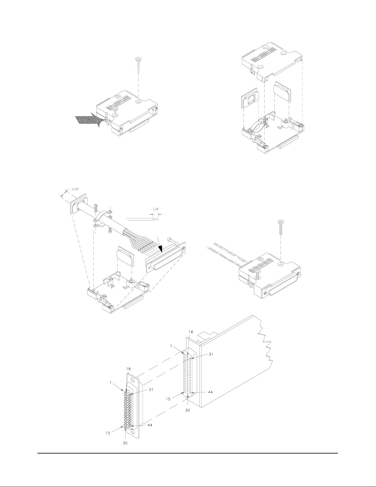
2. Release the latch on the
side of the hood.
3. Assemble bezel and
cable clamp before wiring
cable to connector.
1. If necessary, disassemble
the connector hood. Discard
the three self-tapping screws
supplied with the hood.
4. Wire cable to connector.
(24 AWG or smaller)
6. Assemble connector, cable
strain relief, and hood.
Use the supplied M3x12
machine screws.
5. Place connector and
connector screws on bottom shell.
23
Page 26

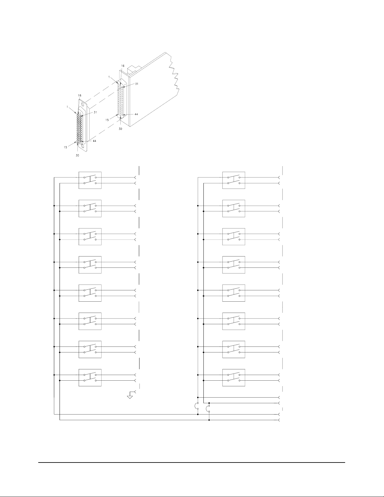
E2259A Double-Wide Breadboard M-Module Wiring Information
24
Page 27
E2259A
J102 Pinout Table
Description Pin Number Pin Number Description
RP712RP6
RP534RP4
RP356RP2
RP178RP0
WP7 9 10 WP6
WP5 11 12 WP4
WP3 13 14 WP2
WP1 15 16 WP0
Busy* 17 18 +5V dc
CRST 19 20 +5V dc
LAT* 21 22 +5V dc
EINT* 23 24 GND
CRST* 25 26 GND
DBEN* 27 28 GND
E2259A
J103 Pinout Table
Description Pin Number Pin Number Description
TR012TR1
TR234TR3
TR456TR5
TR678TR7
TR8 9 10 TR9
TR10 11 12 TR11
TR12 13 14 TR13
TR14 15 16 TR15
BC0 17 18 BC1
BC2 19 20 BC3
BC4 21 22 BC5
BC6 23 24 BC7
BC8 25 26 BC9
BC10 27 28 BC11
BC12 29 30 BC13
BC14 31 32 BC15
GND 33 34 GDN
Chassis GND 35 36 Chassis GND
25
Page 28

E2261A Quad RS-232 Interface Wiring Information
Serial Port 1
Serial Port 2
Serial Port 3
Serial Port 4
HP E2261A Quad Serial M-Module
Pin Name and Function
DTR Data Terminal Ready 1 5 9 13 4
TD Transmitted Data 2 6 10 14 3
RD Received Data 3 7 11 15 2
RTS Request to Send 16 20 24 28 7
CTS Clear to Send 17 21 25 29 8
DSR Data Set Ready 18 22 26 30 6
SG Signal Ground 4, 8, 12, 19, 23, 27 5
{
{
{
{
Port 1
Pin #s
Port 2
Pin #s
Port 3
Pin #s
Port 4
Pin #s
9-Pin Connector
Pin #
Chassis Connection
a. If you use a shielded cable, connect the shield to a chassis connector pin on the 44-pin
connector. Do not connect the other end of the shield.
a
31, 32, 33, . . . 43, 44 -
Note: If you use the optiona l E2261-6 1601 ca ble, you must remo ve the cab le hood i f you inst all t he E2261A in
either of the two internal slots of the E2251A Carrier. The figure on the next page shows the cable wiring for
making your own cable.
26
Page 29

Port 1
Port 2
Note: If you are using shielded cable,
connect the shield to pins 31 - 44
on the 44-pin M-Module connector
only. This connects the shield to the
VXI chassis (earth ground).
Port 3
Port 4
27
Page 30

E2270A 16-Channel Form A Switch Wiring Information
MAXIMUM VOLTAGE/CURRENT: The maximum voltage
that may be applied to any connector on the E2270A,
E2271A, or E2272A is 200 VDC, 125 VA C rms, or 175 VAC
peak. These limits apply only if the product is installed
in a humidity-controlled (<60% RH) environment where
airborne contaminants and transients are controlled,
and there is NOT a relay connection made to power
mains. If these conditions CANNOT be maintaine d, then
the maximum voltage is 60 VD C, 48 VAC rms or 68 VAC
peak.
The maximum current (non-inductive) that may be applied to the E2270A, E2271A, or E2272A is:
Per Switch: 2 ADC, 2 AAC peak
User
Connector
Pins
Per M-Module: 8ADC, 8AAC peak
User
Connector
Pins
Channel 0
Channel 1
Channel 2
Channel 3
Channel 4
Channel 5
Channel 6
Channel 7
1 CH0_NO
16 CH0_COM
2 CH1_NO
17 CH1_COM
3 CH2_NO
18 CH2_COM
4 CH3_NO
19 CH3_COM
5 CH4_NO
20 CH4_COM
6 CH5_NO
21 CH5_COM
7 CH6_NO
22 CH6_COM
8 CH7_NO
23 CH7_COM
Channel 8
Channel 9
Channel 10
Channel 11
Channel 12
Channel 13
Channel 14
Channel 15
9 CH8_NO
24 CH8_COM
10 CH9_NO
25 CH9_COM
11 CH10_NO
26 CH10_COM
12 CH11_NO
27 CH11_COM
13 CH12_NO
28 CH12_COM
14 CH13_NO
29 CH13_COM
15 CH14_NO
30 CH14_COM
43 CH15_NO
44 CH15_COM
31 - 42
28
Page 31

E2271A 4x4 Matrix Switch Wiring Information
MAXIMUM VOLTAGE/CURRENT: The maximum voltage
that may be applied to any connector on the E2270A,
E2271A, or E2272A is 200 VDC, 125 VAC r ms, or 175 VAC
peak. These limits apply only if the product is installed
in a humidity-controlled (<60% RH) environment where
airborne contaminants and transients are controlled,
and there is NOT a relay connection made to power
mains. If these condi tions CANNOT be maintained, then
the maximum voltage is 60 VDC, 48 VAC rms or 68 VAC
peak.
The maximum current (non-inductive) that may be
applied to the E2270A, E2271A, or E2272A is:
Per Switch: 2 ADC, 2 AAC peak
Per M-Module: 8ADC, 8AAC peak
Channel 00 Channel 01 Channel 02 Channel 03
User Connector Pins
4 ROW_0_HI
20 ROW_0_LO
Channel 10 Channel 11 Channel 12 Channel 13
Channel 20 Channel 21 Channel 22 Channel 23
Channel 30 Channel 31 Channel 32 Channel 33
2 COL_0_LO
18 COL_0_HI
16 COL_1_LO
31 COL_1_HI
12 COL_2_LO
28 COL_2_HI
15 COL_3_LO
30 COL_3_HI
6 ROW_1_HI
22 ROW_1_LO
8 ROW_2_HI
24 ROW_2_LO
10 ROW_3_HI
26 ROW_3_LO
1, 3, 5, 7, 9, 11, 13, 14, 17,
19, 21, 23, 25, 27, 29, 32-44
User Connector Pins
29
Page 32
E2272A Dual 8-to-1/Single 16-to-1 Relay Multiplexer Wiring Information
MAXIMUM VOLTAGE/CURRENT: The maximum voltage
that may be applied to any connector on the E2270A,
E2271A, or E2272A is 200 VDC, 125 VAC r ms, or 175 VAC
peak. These limits apply only if the product is installed
in a humidity-controlled (<60% RH) environment where
airborne contaminants and transients are controlled,
and there is NOT a relay connection made to power
mains. If these condi tions CANNOT be maintained, then
the maximum voltage is 60 VDC, 48 VAC rms or 68 VAC
peak.
The maximum current (non-inductive) that may be
applied to the E2270A, E2271A, or E2272A is:
Per Switch: 2 ADC, 2 AAC peak
Per M-Module: 8ADC, 8AAC peak
Channel 0
User Connector Pins
Channel 8
1 CH0_HI
2 CH0_LO
User Connector Pins
25 CH8_HI
9 CH8_LO
Channel 1
Channel 2
Channel 3
Channel 4
Channel 5
Channel 6
Channel 7
18 CH1_HI
33 CH1_LO
17 CH2_HI
32 CH2_LO
16 CH3_HI
31 CH3_LO
22 CH4_HI
6 CH4_LO
21 CH5_HI
5 CH5_LO
20 CH6_HI
4 CH6_LO
19 CH7_HI
3 CH7_LO
Channel 9
26 CH9_HI
10 CH9_LO
Channel 10
27 CH10_HI
11 CH10_LO
Channel 11
28 CH11_HI
12 CH11_LO
Channel 12
13 CH12_HI
29 CH12_LO
Channel 13
15 CH13_HI
14 CH13_LO
Channel 14
30 CH14_HI
44 CH14_LO
Channel 15
43 CH15_HI
42 CH15_LO
30
34 - 41
Single/Dual Mux. Jumpers
8 MUXB_HI_COM
24 MUXB_LO_COM
23 MUXA_HI_COM
7 MUXA_LO_COM
Page 33
Configuring the
E2272A
The following figure shows the two jumper positions for the E2272A. In
position A , the M-Module is configured as a dual 8-to-1 multiplexer. In
position B , the M-Module is configured as a single 16-to-1 multiplexer.
A Du a l 8-to-1Multipl ex e rPo sitio n
B Single 16-to-1 Multiplexer Position
31
Page 34
E2273A 8-Channel Form C Switch Wiring Information
MAXIMUM VOLTAGE/CURRENT: The maximum voltage
that may be applied to any connector on the E2273A is
200 VDC, 141 VAC rms, or 200 VAC peak. These limits
apply only if the product is installed in a humidity-controlled (<60% RH) environmen t w he re a irborne c ontam inants and transients are controlled, and there is NOT a
relay connection made to power mains. If these conditions CANNOT be maintained, then the maximum voltage is 60 VDC, 48 VAC rms or 68 VAC peak.
The maximum current (non-inductive) that may be
applied to the E2273A is 1 ADC, 1 AACpeak per switch.
Maximum power is 40W DC, 40VA AC per switch; 100W
DC, 100VA AC per M-Module.
Channel 0
Channel 1
Channel 2
User
Connector
Pins
1
CH0 NC
3
CH0 NO
2
CH0 com
5
7
CH1 NO
6
9
11
CH1 NC
CH1 com
CH2 NC
CH2 NO
Channel 4
Channel 5
Channel 6
User
Connector
Pins
16
18
17
20
22
21
24
26
CH4 NC
CH4 NO
CH4 com
CH5 NC
CH5 NO
CH5 com
CH6 NC
CH6 NO
32
Channel 3
NC = Normally Closed
NO = Normally Open
com = Common
10
13
15
14
CH2 com
CH3 NC
CH3 NO
CH3 com
Channel 7
CGND: Pin 4, 8, 12, 19, 23, 31 - 44
25
28
30
29
CH6 com
CH7 NC
CH7 NO
CH7 com
Page 35

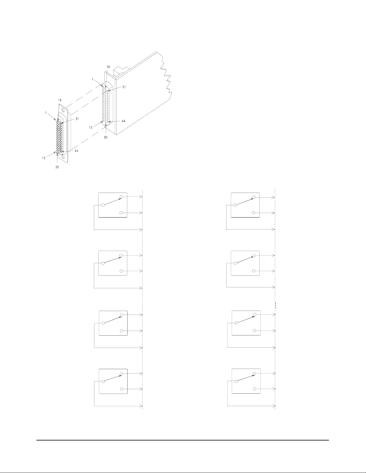
E2274A 4-Channel Power Relay Wiring Information
MAXIMUM VOLTAGE/CURRENT: The maximum voltage
that may be applied to any connector on the E2274A is
125 VDC, 141 VAC rms, or 200 VAC peak. These limits
apply only if the product is installed in a humidity-controlled (<60% RH) environme nt w he re a irborne c ontam inants and transients are controlled, and there is NOT a
relay connection made to power mains. If these conditions CANNOT be maintained, then the maximum voltage is 60 VDC, 48 VAC rms or 68 VAC peak.
The maximum current (non-inductive) that may be
applied to the E2274A is 5 ADC, 5 AACpeak per switch.
Maximum power is 100W DC, 100VA AC, per switch;
300WDC, 300VA AC per M-module.
NC = Norma lly Closed
NO = Normally Open
com = Common
Caution All three connector pins for each relay contact must be
connected together in the field wiring for maximum current
capability. For example, for Channel 1, pins 1, 16, and 31 (for
NC contacts) must be wired toget her in t he field wiring, likewise
pins 3, 18, and 33 (for the NO contact ) and pins 2, 17, and 32 (for
channel common). You may need to run separate wires from
each connector pin and unite them at the device under test or in
your cable.
No Connection: Pins 7, 19, 26
CGND:Pins14,15,30,37,44
33
Page 36
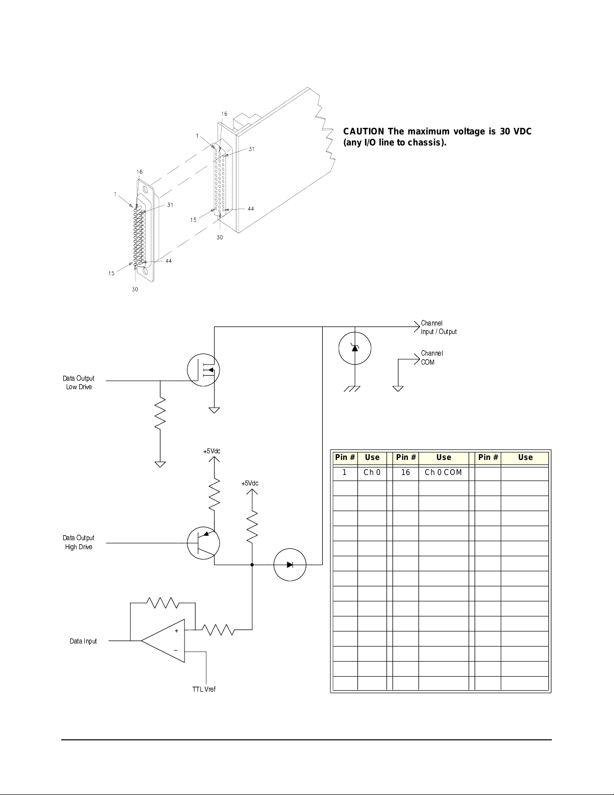
E2290A 16-Bit Digital I/O Wiring Information
CAUTION The maximum voltage is 30 VDC
(any I/O line to chassis).
%BUB 0VUQV U
-PX%SJWF
$IBOOFM
* O Q V U 0V UQ V U
$IBOOFM
$0.
%BUB 0VUQV U
)JHI%SJWF
%BUB * OQ V U
7ED
7ED
@
55- 7S F G
Pin # Use Pin # Use Pin # Use
1 Ch 0 16 Ch 0 COM 31 Chassis
2 Ch 1 17 Ch 1 COM 32 Chassis
3 Ch 2 18 Ch 2 COM 33 Chassis
4 Ch 3 19 Ch 3 COM 34 Chassis
5 Ch 4 20 Ch 4 COM 35 Chassis
6 Ch 5 21 Ch 5 COM 36 Chassis
7 Ch 6 22 Ch 6 COM 37 Chassis
8 Ch 7 23 Ch 7 COM 38 Chassis
9 Ch 8 24 Ch 8 COM 39 Chassis
10 Ch 9 25 Ch 9 COM 40 Chassis
11 CH 10 26 CH 10 COM 41 Chassis
12 CH 11 27 CH 11 COM 42 Chassis
13 Ch 12 28 Ch 12 COM 43 Ch 15
14 Ch 13 29 Ch 13 COM 44 Ch 15 COM
15 Ch 14 30 Ch 14 COM
34
Page 37

E2291A 16-Channel Isolated Digital Output Wiring Information
Note: User must supply +5Vdc to the module. You can supply up to
four isolated supplies (+5V
/TGND4) or they can be combined and one supply used. Refer
+5V
4
to the drawing below.
CAUTION The maximum collector-emitter
voltage is 36 VDC.
/TGND1, +5V2/TGND2, +5V3/TGND3,
1
ЌиззЮЬнил
ϴϾП
ߢ
Ќбϩ ϹϹ
Ќбϩ ϹϺ
Ќбϩ Ϲϻ
ОмЮл
Йвзм
ОмЮл
ЌиззЮЬнил
Йвзм
ϴϾП
Ќбϩ ϹϽ
Ќбϩ ϹϾ
Ќбϩ ϹϿ
ߣ
ϻϻ
Ͼ
ϻϹ
ϻϺ
ϺЁ
Ϻ
ϺϿ
ϺЀ
ϴϾП
Ќбϩ ϹЁ
Ќбϩ ϹЂ
Ќбϩ Ϻ Ϲ
ОмЮл
ЌиззЮЬнил
Йвзм
ߤ
ОмЮл
ЌиззЮЬнил
Йвзм
ϴϾП
Ќбϩ Ϻ ϻ
Ќбϩ Ϻ ϼ
Ќбϩ Ϻ Ͻ
ߥ
ϻЁ
ϺϽ
ϻЂ
ϼϹ
ϻϽ
ϺϹ
ϻϾ
ϻϿ
Ќбϩ Ϲϼ
ϼϺ
ϻϵϩ ϼϵ
НАЗЍ
ЙвзмϩзинϩомЮЭЃϩϽϵϩϺϺϵϩϺϾϵϩϺЂϵϩϻϼϵϩϻЀϵϩϼϽϵϩϽϺ
ϼϻϵϩ ϼϼ
ߢ
Ќбϩ ϹЀ
НАЗЍ
ߣ
ϼϾ
Ͽϵϩ Ѐϵ
ϼϿϵϩ ϼЀ
Ќбϩ Ϻ Ϻ
НАЗЍ
ϽϹ
Ёϵϩ Ђϵ
ϼЁϵϩ ϼЂ
ߤ
Ќбϩ Ϻ Ͼ
НАЗЍ
ߥ
ϽϽ
ϺϻϵϩϺϼϵ
Ͻϻϵ ϩ Ͻϼ
35
Page 38

36
Page 39

Index
E2251A Wiring and Installation Manual
Numerics
16-Channel Switch Wiring, 28
16-to-1 Relay Wiring, 30
4-Channel Power Relay Wiring, 33
4x4 Matrix Switch Wiring, 29
8-Channel Form C Relay Wiring, 32
8-to-1 Relay Wiring, 30
A
Address, Logical, 12
B
Bottom Shield, removing , 10
Bottom Shield, replacin g, 16
Breadboard, Wiring, 24
C
Cable
RS-232, 26
wiring RS-232, 26
Cables, connecting, 18
Carrier
installing into C-Size VXI Mainframe, 17
installing M-Modules onto, 14
removing M-Modules from, 20
slots, 11
Carrier, slots, 12
Caution
disconnect power, 9, 17
M-Module connector alignment, 14
Connect wiring to front M-Modules, 18
Connecting wiring to interior M-Modules, 15
Connector
assembly, 22
wiring, 22
E
Extraction levers, 17
E2259A Wiring Information, 24
E2261A Wiring Information, 26
E2270A Wiring Information, 28
E2271A Wiring Information, 29
E2272A Wiring Information, 30
E2273A Wiring Information, 32
E2274A Wiring Information, 33
E2290A Wiring Information, 34
E2291A Wiring Information, 35
F
Field Wiring Diagrams, 21
Form A Switch Wiring, 28
Form C Relay Wiring, 32
G
Guidelines for determini ng log ica l addr esses, 12
H
Hood, connector, 22
I
Install Carrier into C-Size VXI Mainframe, 17
Installation, verifying VXIplug&play, soft front
panels
, 19
Installing Carrier in Mainframe, 17
Installing Dress Panels, 15
Installing M-Modules, 14
Interior M-Modules, connecting wiring, 15
Interior slots, 11
Interior wiring, connecting, 15
Internal slots, 11
Isolated Digital Output Wiring, 35
D
Digital I/O Wiring, 34
Digital Output Wiring, 35
Dress Panels, 14, 15
Drivers
SCPI, 9
VXIplug&play, 9
L
labels, 16
Layout, M-Module, 11
Logical Address, 12
M
Mainframe, installing Carrier, 17
MA-Module Support, 9
Matrix Switch Wiring, 29
Index 37
Page 40

M-Module
position in Carrier, 11
removing from Carrier, 20
slots, 11
M-Module mating connectors, 15
M-Module Wiring Diagrams, 21
M-Modules
installing, 14
M-Modules, connecting interior wiring, 15
M-Modules, wiring front, 18
Module layout, 11
Multiple Module Instruments, 12
Multiplexer Wiring, 30
O
Operational Verification, 19
P
Placing M-Modules in Carrier, 11
Power Relay Wiring, 33
Power-on Test, 19
R
Removing M-Module from Carrier , 20
Removing shields, 10
Replacing Bottom Shield, 16
Replacing Top Shield, 16
RFI, minimizing, 14, 15
RS-232 Wiring, 26
V
Verify M-Module Installation, 19
VXI Mainframe, installing Carrier in, 17
VXIplug&play, 9
VXIplug&play driver, see CDROM
VXIplug&play function reference, see CDROM
VXIplug&play programs, see CDROM
VXIplug&play soft front panels, see CDROM
W
Wiring Diagrams, 21
Wiring front M-Modules, 18
Wiring Information
E2259A, 24
E2261A, 26
E2270A, 28
E2271A, 29
E2272A, 30
E2273A, 32
E2274A, 33
E2290A, 34
E2291A, 35
Wiring, connecting to interior M-Modules, 15
S
Scanning Voltmeter, 12
SCPI Drivers, 9
Serial Port Wiring, 26
Shields, removing, 10
Shields, replacing, 16
Slots in Carr ier, 12
Switchbox, 12, 12
T
Top Shield, removing, 10
Top Shield, replacing, 16
U
Unused slots in Carrier , 12
38 Index
 Loading...