

Page 1

Agilent E2050 LAN/GPIB
Gateway Installation and
Configuration Guide
Manual Part Number: E2050-90003
Printed in U.S.A. E0701
Page 2

Page 3

Contents
E2050 LAN/GPIB Gateway User’s Guide
Front Matter............................................................................................... 5
Warranty Information .................................................................... 5
Contacting Agilent ......................................................................... 6
Safety Considerations ................................................................... 7
Radio and Television Interference ................................................ 7
Declaration of Conformity .............................................................. 9
1. Introduction ........................................................................................ 11
How to Use This Guide ................................................................ 13
Guide Contents .................................................................... 13
Related Software Documentation ......................................... 14
E2050 Hardware Description ....................................................... 15
E2050 LAN/GPIB Gateway Front Panel ............................... 15
E2050 LAN/GPIB Gateway Rear Panel ............................... 16
AC/DC Adapter and AC Power Cord .................................... 17
Rack Mount Kit (Optional) .................................................... 17
E2050 Software/Firmware Architecture ....................................... 18
I/O Application Software Supported ..................................... 18
Typical LAN Connections ..................................................... 19
Software/Firmware Architecture Overview ........................... 21
Using Application Software .................................................. 22
2. Installation .......................................................................................... 23
Hardware Requirements .............................................................. 25
Software Requirements ............................................................... 26
Installing the Hardware ................................................................ 27
3. Configuration ..................................................................................... 33
Setting Configuration Values ....................................................... 35
Steps to Set Configuration Values ....................................... 35
Configuration Values Descriptions ....................................... 35
How Configuration Values are Used .................................... 41
Configuration Methods................................................................. 43
Configuration Methods Overview ......................................... 43
Using Telnet Configuration Method (Windows) .................... 45
Using Telnet Configuration Method (HP-UX) ....................... 50
Using BOOTP Configuration Method (HP-UX) ..................... 55
Using BOOTP with TFTP Configuration Method (HP-UX) ... 58
Contents 3
Page 4

4. Administration ....................................................................................63
Using the Telnet Utility.................................................................. 65
Accessing the Telnet Utility ...................................................65
Exiting the Telnet Utility ........................................................68
Telnet Commands ................................................................. 68
Querying the Gateway..................................................................70
Querying the Current Configuration ......................................70
Querying the Firmware Revision ...........................................70
Querying the Configuration Method ......................................71
Querying Gateway/Client Connections .................................71
Configuring the Gateway ..............................................................75
Setting Default Configuration Values ....................................75
Changing the Configuration Method .....................................75
Using the Gateway’s syslog File ...........................................77
Terminating Client Connections ............................................79
5. Troubleshooting .................................................................................81
Gateway Failure Messages ..........................................................83
SICL Error Codes and Messages .........................................83
syslog File Messages ............................................................ 84
Troubleshooting Network Configuration .......................................85
Verifying Network Connections .............................................85
Troubleshooting Network Configurations ..............................86
Troubleshooting Gateway Configuration ......................................88
Verifying Gateway Configuration ..........................................88
Setting Default Configuration ................................................88
Verifying the Configuration Method .......................................89
Changing the Configuration Method .....................................91
Troubleshooting Telnet Configuration ...................................92
Troubleshooting BOOTP Configuration ................................92
Troubleshooting BOOTP with TFTP Configuration ...............93
Troubleshooting Client Connections.............................................94
Client Connection Problems .................................................94
Client Run-time Errors ..........................................................96
A. Specifications ...................................................................................99
Glossary ................................................................................................103
Index ......................................................................................................107
Contents 4
Page 5

Notice
The information contained in this document is subject to change without
notice.
Agilent Technologies shall not be liable for any errors contained in this
document. Agilent Technologies makes no warranties of any kind with
regard to this document, whether express or implied. Agilent Technologies
specifically disclaims the implied warranties of merchantability and fitness
for a particular purpose. Agilent Technologies shall not be liable for any
direct, indirect, special, incidental, or consequential damages, whether
based on contract, tort, or any other legal theory, in connection with the
furnishing of this document or the use of the information in this document.
Warranty Information
A copy of the specific warranty terms applicable to your Agilent
Technologies product and replacement parts can be obtained from Agilent
Technologies, Inc.
U.S. Government Restricted Rights
The Software and Documentation have been developed entirely at private
expense. They are delivered and licensed as "commercial computer
software" as defined in DFARS 252.227- 7013 (Oct 1988), DFARS 252.2117015 (May 1991) or DFARS 252.227-7014 (Jun 1995), as a "commercial
item" as defined in FAR 2.101(a), or as "Restricted computer software" as
defined in FAR 52.227-19 (Jun 1987) (or any equivalent agency regulation
or contract clause), whichever is applicable. You have only those rights
provided for such Software and Documentation by the applicable FAR or
DFARS clause or the Agilent standard software agreement for the product
involved.
5
Page 6

Trademark Information
Microsoft®, Windows ® 95, Windows ® 98, Windows ® Me,
Windows ® 2000, and Windows NT® are U.S. registered trademarks of
Microsoft Corporation. All other brand and product names are trademarks
or registered trademarks of their respective companies.
This software and documentation are based in part on the Fourth Berkeley
Software Distribution under license from The Regents of the University of
California. We acknowledge the Regents of the University of California for
their role in the development of this software and documentation.
Printing History
Edition 1 - February 1995
Edition 2 - November 1995
Edition 3 - May 1996
Edition 4 - July 2001
Copyright Information
Agilent Technologies E2050 LAN/GPIB Gateway
Installation and Configuration Guide
Edition 4
Portions of the TCP/IP software are copyright Phil Karn, KA9Q.
Copyright © 1984, 1985, 1986, 1987, 1988 Sun Microsystems, Inc.
Copyright © 1995-1996, 2001 Agilent Technologies, Inc.
All rights reserved.
Contacting Agilent
n In the USA and Canada, you can reach Agilent Technologies at
these telephone numbers:
USA: 1-800-452-4844
Canada: 1-877-894-4414
n Outside the USA and Canada, contact your country’s Agilent support
organization. A list of contact information for other countries is
available on the Agilent web site:
http://www.agilent.com/find/assist
6
Page 7

Safety Considerations
Product and Documentation Labels
A WARNING denotes a hazard that can cause injury or death. A CAUTION
denotes a hazard that can damage equipment or cause data loss. Do not
proceed beyond a WARNING or CAUTION notice until you understand the
hazardous conditions and have taken appropriate steps.
Grounding
The power module (Agilent 0950-2546 AC/DC Adapter) is a safety class I
product and has a protective earthing terminal. There must be an
uninterruptible safety earth ground from the main power source to the
product’s input wiring terminals, power cord, or power cord set. Whenever it
is likely that the protection has been impaired, disconnect the power cord
until the ground has been restored.
Servicing
There are no user-serviceable parts inside the E2050 LAN/GPIB Gateway or
its power module (AC/DC Adapter). Any servicing, adjustment,
maintenance, or repair must be performed by service-trained personnel
only. The power module does not have a power switch. The power cord is
intended to serve as the disconnect device. Make sure the power module is
installed near a wall outlet and is easily accessible.
Radio and Television Interference
This device has been verified to comply with FCC Rules Part 15. Operation
is subject to these two conditions: (1) this device may not cause radio
interference, and (2) this device must accept any interference received
(including interference that may cause undesired operation).
This equipment generates and uses radio frequency energy. If not installed
and used in accordance with this manual, it can cause interference to radio
and television communications. The rules with which it must comply afford
reasonable protection against such interference when it is used in most
locations.
However, there can be no guarantee that such interference will not occur in
a particular installation. If you think your device is causing interference, turn
off the system. If the radio or television reception does not improve, your
device is probably not causing the interference.
7
Page 8

If your device does cause interference to radio and television reception, you
are encouraged to try to correct the interference by one or more of the
following measures:
n Relocate the radio or TV antenna.
n Move the device away from the radio or television.
n Plug the device into a different electrical outlet, so that the device
and the radio or television are on separate electrical circuits.
n Make sure you use only shielded cables to connect peripherals to
your device.
n Consult your dealer, Agilent Technologies, or an experienced radio/
television technician for other suggestions.
n Order the FCC booklet How to Identify and Resolve Radio-TV
Interference Problems from the U.S. Government Printing Office,
Washington, D.C. 20402. The stock number of this booklet is
004-000-00345-4.
8
Page 9

DECLARATION OF CONFORMITY
According to ISO/IEC Guide 22 and CEN/CENELEC EN 45014
Manufacturer’s Name: Agilent Technologies, Incorporated
Manufacturer’s Address: 815 - 14th St. SW
Loveland, Colorado 80537
USA
Declares, that the product
Product Name: LAN/GPIB Gateway
Model Number: E2050B
Product Options: This declaration covers all options of the above product(s).
Conforms with the following European Directives:
The product herewith complies with the requirements of the Low Voltage Directive 73/23/EEC and the
EMC Directive 89/336/EEC (including 93/68/EEC) and carries the CE Marking accordingly.
Conforms with the following product standards:
EMC Standard Limit
IEC 61326-1:1997+A1:1998 / EN 61326-1:1997+A1:1998
CISPR 11:1990 / EN 55011:1991
IEC 61000-4-2:1995+A1:1998 / EN 61000-4-2:1995
IEC 61000-4-3:1995 / EN 61000-4-3:1995
IEC 61000-4-4:1995 / EN 61000-4-4:1995
IEC 61000-4-5:1995 / EN 61000-4-5:1995
IEC 61000-4-6:1996 / EN 61000-4-6:1996
IEC 61000-4-11:1994 / EN 61000-4-11:1994
Canada: ICES-001:1998
Australia/New Zealand: AS/NZS 2064.1
The product was tested in a typical configuration with Agilent Technologies test systems
Group 1 Class A
4kV CD, 8kV AD
3 V/m, 80-1000 MHz
0.5kV signal lines, 1kV power lines
0.5 kV line-line, 1 kV line-ground
3V, 0.15-80 MHz
Dips: 30% 10ms; 60% 100ms
Interrupt > 95%@5000ms
Safety
IEC 61010-1:1990+A1:1992+A2:1995 / EN 61010-1:1993+A2:1995
Canada: CSA C22.2 No. 1010.1:1992
UL 3111-1: 1994
21 June 2001
Date Ray Corson
Product Regulations Program Manager
For further information, please contact your local Agilent Technologies sales office, agent or distributor. Authorized
EU-representative: Agilent Technologies Deutschland GmbH, Herrenberger Straße 130, D 71034 Böblingen, Germany
9
Page 10

10
Page 11

1
Introduction
11
Page 12

Introduction
This Agilent E2050 LAN/GPIB Gateway Installation and Configuration Guide
gives guidelines to install and configure the E2050 LAN/GPIB Gateway
(Gateway) for use with supported, network-equipped computer systems.
You can also use this guide to administer the Gateway on your network and
to troubleshoot installation or configuration problems. This chapter includes:
n How to Use This Guide
n E2050 Hardware Description
n E2050 Software/Firmware Architecture
12 Chapter 1
Page 13

Introduction
How to Use This Guide
How to Use This Guide
The information in this guide assumes you are a Network Administrator who
installs, configures, and maintains a local area network (LAN), including
network-related hardware like the E2050 LAN/GPIB Gateway.
If you use a Series 700 HP-UX workstation with the Gateway, you must
also have super-user (root) privileges on the HP-UX system. If you use a
Windows NT PC with the Gateway, you must also have system
administrator privileges on the Windows NT PC.
Guide Contents
Chapter Description
Chapter 1 - Overview Provides an overview of the E2050 LAN/GPIB Gateway.
Chapter 2 - Installation Shows how to install the Gateway on LAN and GPIB.
Chapter 3 - Configuration Shows how to configure the Gateway on your network.
Chapter 4 - Administration Shows how to maintain the Gateway on the network.
Chapter 5 - Troubleshooting Provides ways to fix problems with the Gateway.
Appendix A - Specifications Provides specifications for the Gateway.
Glossary Technical terms used in this guide.
Chapter 1 13
Page 14

Introduction
How to Use This Guide
Related Software Documentation
Suggested software manuals you can use for E2050 LAN/GPIB Gateway
operation with the listed I/O application software products follow. The E2050
Gateway supports all I/O application operations by these software products
except for parallel polling, SICL commander sessions, and asynchronous
aborting.
Product Related Documentation
VISA To use the LAN/GPIB Gateway, you must configure the LAN Client software
provided with VISA. See the Agilent I/O Libraries Installation and
Configuration Guide for configuration procedures. To develop and use VISA
I/O applications for the Gateway, see Agilent VISA User’s Guide.
SICL To use the LAN/GPIB Gateway, you must configure the LAN Client software
provided with SICL. See the Agilent I/O Libraries Installation and
Configuration Guide for configuration procedures.
To develop and use SICL I/O applications for the Gateway in Windows, see
the Agilent SICL User’s Guide for Windows. To develop and use SICL I/O
applications for the Gateway in HP-UX, see the Agilent SICL User’s Guide
for HP-UX.
VEE To use the LAN/GPIB Gateway, see the VEE User’s Manual for configuration
procedures. To develop and use VEE I/O applications for the Gateway, see
the VEE User’s Manual.
BASIC/
UX 700
Versi on 8 .x
To use the LAN/GPIB Gateway, you must configure the SICL LAN Client
software provided with BASIC/UX 700 Version 8.x. See the Installing and
Using BASIC/UX 8.x manual for configuration procedures. To develop and
use BASIC/UX 700 Version 8.x I/O applications for the Gateway, see the
BASIC Interface Reference manual.
Versi on 7 .1
To use the LAN/GPIB Gateway, you must configure the SICL LAN Client
software provided with BASIC/UX 700 Version 7.1. See the Installing and
Maintaining HP BASIC/UX manual for configuration procedures. To develop
and use BASIC/UX 700 Version 7.1 I/O applications for the Gateway, see the
BASIC Interface Reference manual.
14 Chapter 1
Page 15
E2050 Hardware Description
E2050 Hardware Description
In addition to this guide, the E2050 product package consists of:
n E2050 LAN/GPIB Gateway Front Panel
n E2050 LAN/GPIB Gateway Rear Panel
n AC/DC Adapter and Standard AC Power Cord
n Rack Mount Kit (Optional)
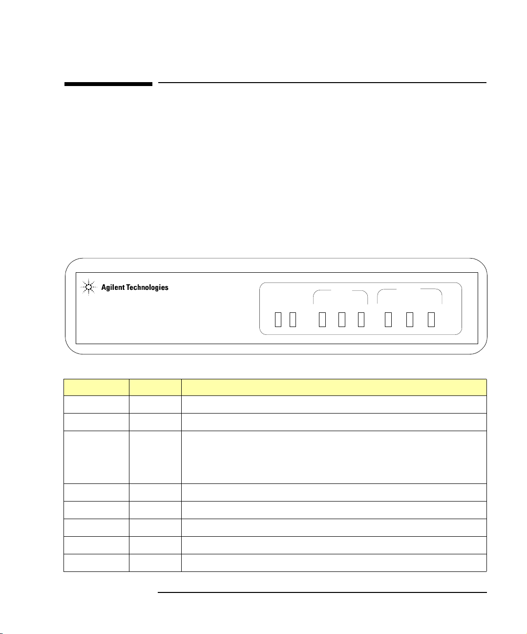
E2050 LAN/GPIB Gateway Front Panel
As shown in the following figure, the front panel of the Gateway contains
8 light-emitting diodes (LEDs) that indicate the status of the Gateway.
LAN/GPIB Gateway
Power Fail Conn Tx Rx Talk Listen SRQ
E2050 LAN GPIB
Introduction
E2050 LAN/GPIB Gateway Front Panel
LED Color Meaning When Illuminated
Power
Fault
LAN Conn
Green Power is applied to the Gateway.
Red Diagnostic failure of the hardware. This LED will normally be off.
Yellow A TCP/IP port is open (Telnet or a LAN connection). Flashes at a
fast rate for BOOTP or a BOOTP with TFTP configuration. Flashes
at a slow rate when the default IP address (
LAN Tx
LAN Rx
GPIB Talk
GPIB Listen
GPIB SRQ
(after the
Yellow Flashes at 10 Hz rate when transmitting packets on the LAN.
Yellow Flashes at 10 Hz rate when receiving packets from the LAN.
Yellow The Gateway is configured to TALK on the GPIB bus.
Yellow The Gateway is configured to LISTEN on the GPIB bus.
Yellow The GPIB SRQ line is asserted.
Config Preset button is pressed).
Chapter 1 15
192.0.0.192) is used
Page 16
Introduction
E2050 Hardware Description
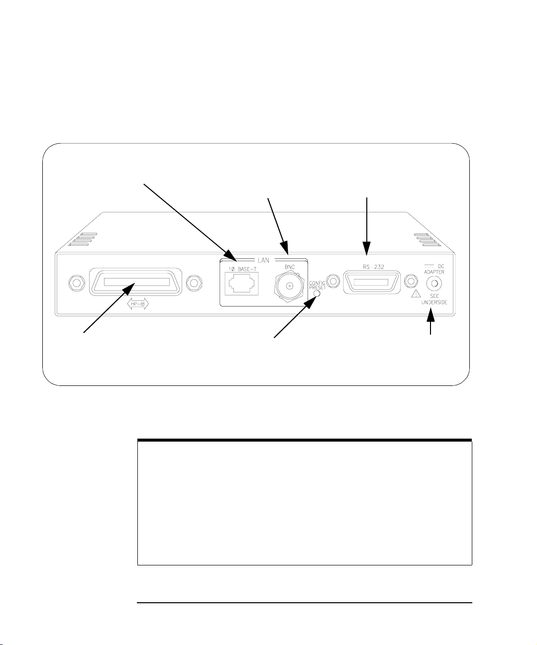
E2050 LAN/GPIB Gateway Rear Panel
This figure shows the back panel features of the Gateway. Note that the
RS-232 interface is NOT supported for I/O application use..
RJ-45 connector for 10 Base-T,
unshielded twisted-pair cable
(Ethertwist LAN)
GPIB Connector
Config Preset button for resetting
the Gateway to its factory-set
default configuration values
E2050 LAN/GPIB Gateway Rear Panel
NOTE
BNC connector for
10 Base2, thin coaxial
cable (ThinLAN)
RS-232 connector (the RS-232
interface is not supported for I/O
application use)
Power input for the DC
cable from the AC/DC
Adapter (power module)
Converters are available that provide an Attachment Unit Interface (AUI)
connection (10 Base-T to DB15 AUI port) for ThickLAN or fiber optic
networks (for Ethernet/IEEE 802.3 protocol).
You will need to purchase both a converter and a Medium Attachment
Unit (MAU) to use the E2050 LAN/GPIB Gateway with ThickLAN or a
fiber optic network. Contact Agilent Technologies for information on these
and other networking products.
16 Chapter 1
Page 17
Introduction
E2050 Hardware Description
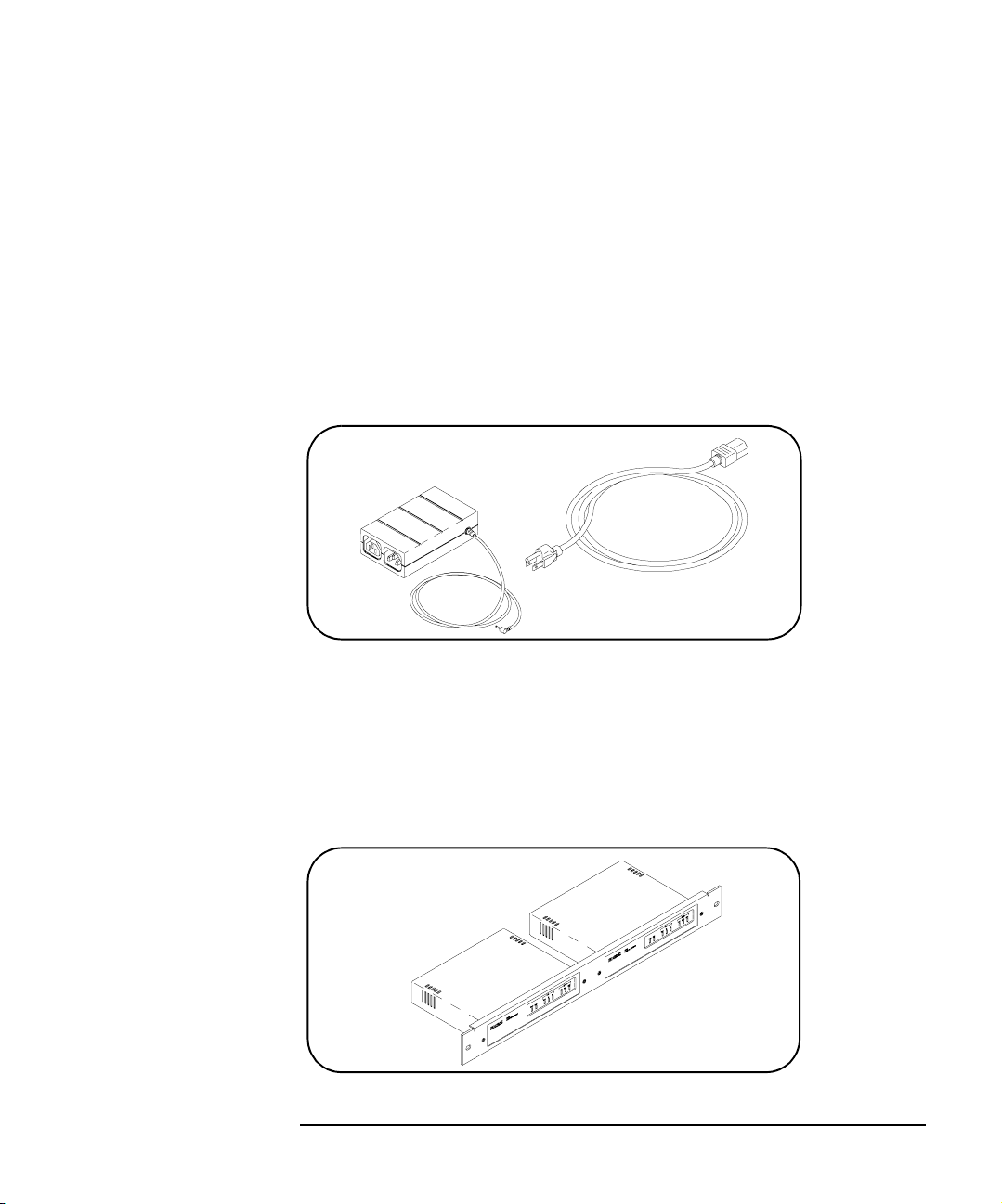
AC/DC Adapter and AC Power Cord
As shown in the following figure, the power module (AC/DC Adapter)
(Agilent part number 0950-2546) provides 5 Vdc power to the Gateway. The
4-foot, DC cable attached to the power module connects to the power input
on the back panel of the Gateway. The universal AC outlets on the power
module can automatically accept and adapt to 100-240 Vac power.
The separate AC power cord connects to the AC IN outlet on the power
module and to a power outlet (wall outlet), thus providing power to the power
module and Gateway. You should have received the appropriate AC power
cord for your country.
AC/DC Adapter and Standard AC Power Cord
Rack Mount Kit (Optional)
As shown in the following figure, this optionally purchased E2051 Rack
Mount Kit allows you to mount up to two LAN/GPIB Gateways in a rack
frame. A light-duty, fixed shelf is also required. It is recommended you use
an Agilent E3666 Plain Shelf with this rack mount kit.
Rack Mount Kit (Optional)
Chapter 1 17
Page 18

Introduction
E2050 Software/Firmware Architecture
E2050 Software/Firmware Architecture
This section describes E2050 software/firmware architecture, including:
n I/O Application Software Supported
n Typical LAN Connections
n Software/Firmware Overview
n Using Applications Software
I/O Application Software Supported
The E2050 LAN/GPIB Gateway supports these I/O application software
products. The Gateway supports all I/O application operations provided by
these software products except for parallel polling, SICL commander
sessions, and asynchronous aborting.
n Agilent Virtual Instrument Software Architecture (VISA) on HP-UX or
on Microsoft Windows 95, Windows 98, Windows 2000, Windows
Me, or Windows NT (for WIN32 applications only), as applicable.
n Agilent Standard Instrument Control Library (SICL) on HP-UX or on
Microsoft Windows 95, Windows 98, Windows 2000, Windows Me,
or Windows NT (for WIN32 applications only).
n Agilent Visual Engineering Environment (VEE) on HP-UX or on
Microsoft Windows 95, Windows 98, Windows 2000, Windows Me,
or Windows NT (for WIN32 applications only).
n HP BASIC/UX 700 Version 7.1 or Version 8.x on HP-UX.
18 Chapter 1
Page 19
Introduction
E2050 Software/Firmware Architecture
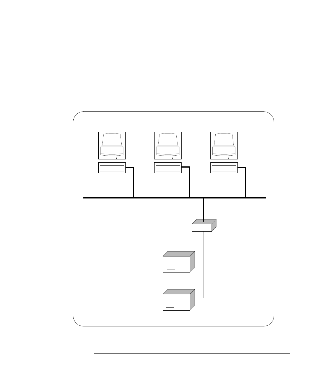
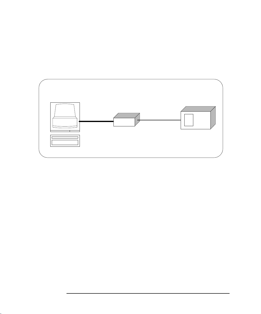
Typical LAN Connections
The E2050 LAN/GPIB Gateway combines hardware and firmware in a single
box that provides a network gateway between network-equipped computer
systems and GPIB based instruments. The Gateway enables users of I/O
applications to obtain measurement data either locally or remotely from
GPIB instrumentation. The following figure shows typical LAN connections
for an E2050 Gateway.
Computer Systems
LAN
E2050
LAN/GPIB
Gateway
GPIB Instruments
LAN
GPIB
bus
Typical LAN Connections
Chapter 1 19
Page 20
Introduction
E2050 Software/Firmware Architecture
The Gateway connects the local area network (LAN) from the computer
system to the GPIB bus. Network-equipped computer systems that are
supported for use with the Gateway include Series 700 workstations and
32-bit PCs. Following the client/server model of computing, the computer
system is the
client, and the E2050 LAN/GPIB Gateway acts as the server.
Client System
Thus, I/O applications running on the computer system can transparently
interface to GPIB-based instruments over the LAN. Since several computer
systems can access the LAN/GPIB Gateway, groups of users can share
access to the same GPIB instruments via the Gateway. In addition, existing
I/O applications that are supported with the LAN/GPIB Gateway and are
designed for GPIB can use the Gateway without modification beyond an
address change.
The Gateway and its attached GPIB instruments can be placed anywhere
on the network (rather than with a particular controller or server computer
system). This includes networks which span different geographic locations,
such as when networked computer systems are located at several different
sites. Hence, GPIB instruments can be located where they are most
convenient for I/O application users.
Server
E2050
LAN
Client - Server Configuration
GPIB Instrument
GPIB bus
In addition, you can have more than one LAN/GPIB Gateway on a network,
providing “clusters” of GPIB instrumentation at different locations. This
further aids users in accessing the instrumentation they need for their
specific I/O applications.
20 Chapter 1
Page 21

Introduction
E2050 Software/Firmware Architecture
Software/Firmware Architecture Overview
Agilent SICL contains the LAN client software needed to access the
LAN/GPIB Gateway. Thus, SICL is also provided with the VISA, VEE, and
HP BASIC/UX 700 I/O application software products. To use any of these
software products with the LAN/GPIB Gateway, you must also install and
configure SICL on the client computer system.
Several of these software products support two different LAN networking
protocols: the SICL LAN Protocol and the TCP/IP Instrument Protocol.
Version A.01.00 or later of the LAN/GPIB Gateway supports the SICL LAN
Protocol and VXI-11 (TCP/IP Instrument Protocol). To check your version of
the Gateway (and the protocol(s) you can use with the Gateway depending
on the software product you have), see Chapter 4.
As shown in the following figure, the client system contains the LAN client
software provided with SICL as well as the TCP/IP LAN software needed to
access the Gateway. The Gateway contains LAN server and TCP/IP LAN
firmware so that it acts as the LAN server.
The LAN client software provided with SICL uses the TCP/IP LAN protocol
suite to pass messages between the client system and the server (the
E2050 LAN/GPIB Gateway). Therefore, the client sends I/O requests over
the network to the server. The server then executes those I/O requests on
the appropriate GPIB based instrument(s) connected to the server.
Client System
Application
Agilent VISA
SICL
LAN Client
TCP
IP
LAN Interface
Server (E2050) Instrument
LAN Server
TCP
Instrument
IP Driver
LAN Interface
GPIB bus (or other)
Instrument
Firmware
Software/Firmware Architecture
Chapter 1 21
Page 22

Introduction
E2050 Software/Firmware Architecture
Using Application Software
This section summarizes how the software on a client computer system
works with the E2050 LAN/GPIB Gateway to complete I/O application
operations on attached GPIB instruments. For more information on how to
use your software with the Gateway, see the applicable software
documentation as listed in “Related Software Documentation”.
Establishing a
Network Connection
Maximum Client
Connections
I/O Application
Operation
Before trying to perform an I/O application operation on the Gateway’s
GPIB interface and the GPIB bus, the LAN client software in the client
computer system establishes a network connection to the LAN server (the
Gateway). Once the client establishes a connection, the client can begin to
send I/O requests to the Gateway.
The Gateway (LAN server) can have multiple clients connected and being
serviced at any given time. The maximum number of concurrent client
connections depends on memory usage in the Gateway, including the
number of clients and the number of current sessions running on those
clients. However, at least 8, but not more than 15, client connections can be
running concurrently. Thus, if the maximum number of client connections to
the Gateway has not been exceeded, the connection is allowed to occur.
Although several instruments can be connected to the Gateway’s GPIB bus,
only one I/O application operation can occur on the GPIB bus at any given
time. Therefore, once a client’s request begins to execute on the GPIB, all
other client requests for operations on the GPIB must wait until the current
client request completes. Client requests are serviced in a first come, first
served manner, unless they are prohibited by interface or device locks.
Using Locks If a client has a sequence of I/O application operations to perform that
should not be preempted, the client should obtain a lock on the Gateway’s
GPIB interface or device. Once the client’s sequence has completed, it
should release its lock, allowing other clients access.
Closing a Network
Connection
When a client closes a connection, the Gateway frees up the resources
allocated to that client, including any locks, pending I/O requests, memory
usage, etc. Abnormal termination (for example, the network and/or client
goes down) is discussed in Chapter 5.
22 Chapter 1
Page 23

2
Installation
23
Page 24

Installation
This chapter shows how to install the E2050 LAN/GPIB Gateway on the
LAN and the GPIB bus for use with network-equipped computer systems,
including:
n Hardware Requirements
n Software Requirements
n Hardware Installation
24 Chapter 2
Page 25

Installation
Hardware Requirements
Hardware Requirements
To install the Gateway, you must have the following hardware:
n One or more of these network-equipped computer systems to act as
the LAN client system(s):
q HP 9000 Series 700 workstation
q 32-bit personal computer (PC)
n A local area network (LAN) to which the client system(s) and the
E2050 LAN/GPIB Gateway can connect via the appropriate LAN
cables.
n The E2050 LAN/GPIB Gateway.
n The power module and standard power cord to provide power to the
Gateway.
n Optionally, a separately purchased rack mount kit in which you can
mount the Gateway.
n GPIB instrument(s), including the GPIB cable(s) needed to connect
the Gateway to the instrument(s).
Chapter 2 25
Page 26

Installation
Software Requirements
Software Requirements
Each client computer system that will access the Gateway must be running
one of the following operating systems.
n HP-UX Version 9 or Version 10.01 or later (for Series 700
workstations)
n Microsoft Windows 95, Windows 98, Windows 2000, Windows Me,
or Windows NT (for 32-bit PCs)
You must also have one or more of the following I/O application products
installed and configured on each client computer system that you want to
use with the Gateway.
n Agilent I/O Libraries, including one or more of the following:
q Agilent VISA on HP-UX or on Microsoft Windows 95,
Windows 98, Windows 2000, Windows Me, or Windows NT
(for WIN32 applications only) as applicable.
q Agilent SICL on HP-UX or on Microsoft Windows 95,
Windows 98, Windows 2000, Windows Me, or Windows NT
(for WIN32 applications only).
q Agilent VEE on HP-UX or on Microsoft Windows 95,
Windows 98, Windows 2000, Windows Me, or Windows NT
(for WIN32 applications only)
q HP BASIC/UX 700 Version 7.1 or Version 8.x on HP-UX.
For information on configuring these software products for use with the
Gateway, see “Related Software Documentation” in Chapter 1.
26 Chapter 2
Page 27

Installation
Installing the Hardware
Installing the Hardware
This section shows how to install the LAN/GPIB Gateway hardware by
connecting it to the LAN, GPIB bus, and power module.
Step 1: Record LAN Hardware Address
First, find the hardware address of the LAN interface in the E2050
LAN/GPIB Gateway. Turn the Gateway over and look for the label on the
underside of the Gateway. The hardware address on the label will be similar
to 0800XXXXXX. Write down this address, as you may need it later to
configure the Gateway on the network.
CAUTION: Use only Agilent Technologies
specified AC - DC adaptor.
CAUTION:
Refer servicing to qualified personnel.
POWER: Input: 5V DC, 6 watts
No operator serviceable parts inside.
ISM 1-A
Made in U.S.A. of domestic and foreign components
N279
LAN HARDWARE ADDRESS
0800fffffef6
Finding the LAN Hardware Address (MAC)
Step 2: Configure the Network
n If you purchased the optional rack mount kit, follow that kit’s
documentation to assemble the rack and to install the Gateway
in the rack’s frame.
n Make sure the GPIB instrumentation you will connect to the
Gateway is working properly and is connected to the GPIB bus.
Chapter 2 27
Page 28
Installation
Installing the Hardware
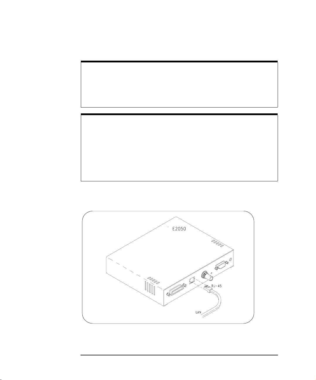
Step 3: Connect the Gateway to the Network
CAUTION
Do not connect to both the RJ-45 and the BNC connectors on the
Gateway. Only one connection to the LAN interface in the Gateway can
be made at a time. Data loss may occur if you try to use both connectors
simultaneously. The Gateway will automatically select the active port.
NOTE
To connect the Gateway to a ThickLAN or fiber optic network, see the
hardware documentation for with your ThickLAN or fiber optic network to
connect the LAN cable to the RJ-45 connector on the Gateway.
To connect the Gateway directly to a client computer system, you will
need a special twisted-pair cable. Contact Agilent Technologies for more
information.
n Ethertwist Connection. For Ethertwist, connect the LAN cable to the
RJ-45 connector on the back panel of the Gateway.
Connecting to an Ethertwist LAN Using an RJ-45 Connector
28 Chapter 2
Page 29
Installation
Installing the Hardware
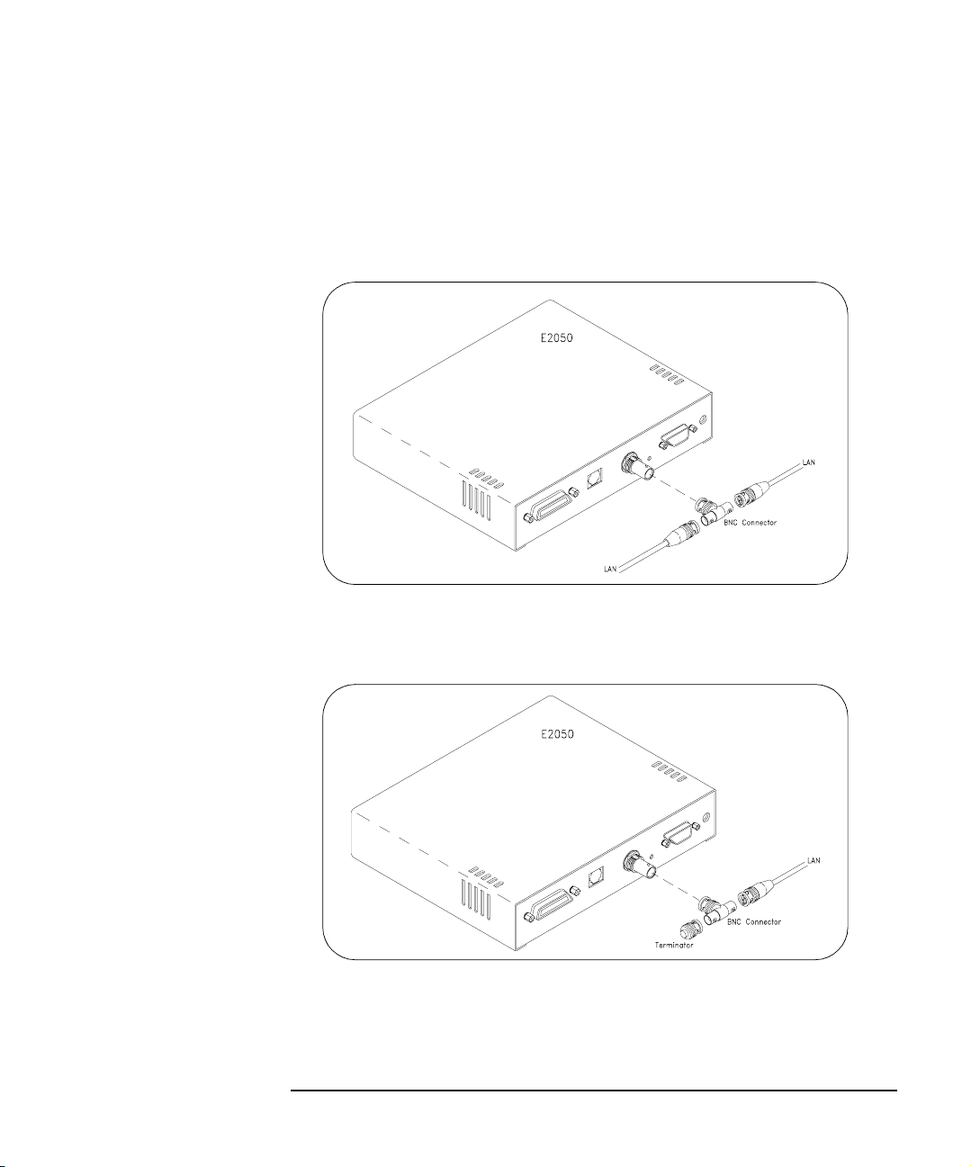
n ThinLAN Connections. For ThinLAN, connect the LAN cable to the
BNC connector on the back panel of the Gateway using a BNC “T”
connector. Make sure the ThinLAN segment is properly terminated.
If the Gateway is the end node on the LAN, a 50-ohm BNC
terminator must be attached to the “T” connector.
Connecting to a ThinLAN Using a BNC “T” Connector
Connecting to a ThinLAN Using a BNC “T” Connector and 50-Ohm Terminator
Chapter 2 29
Page 30
Installation
Installing the Hardware
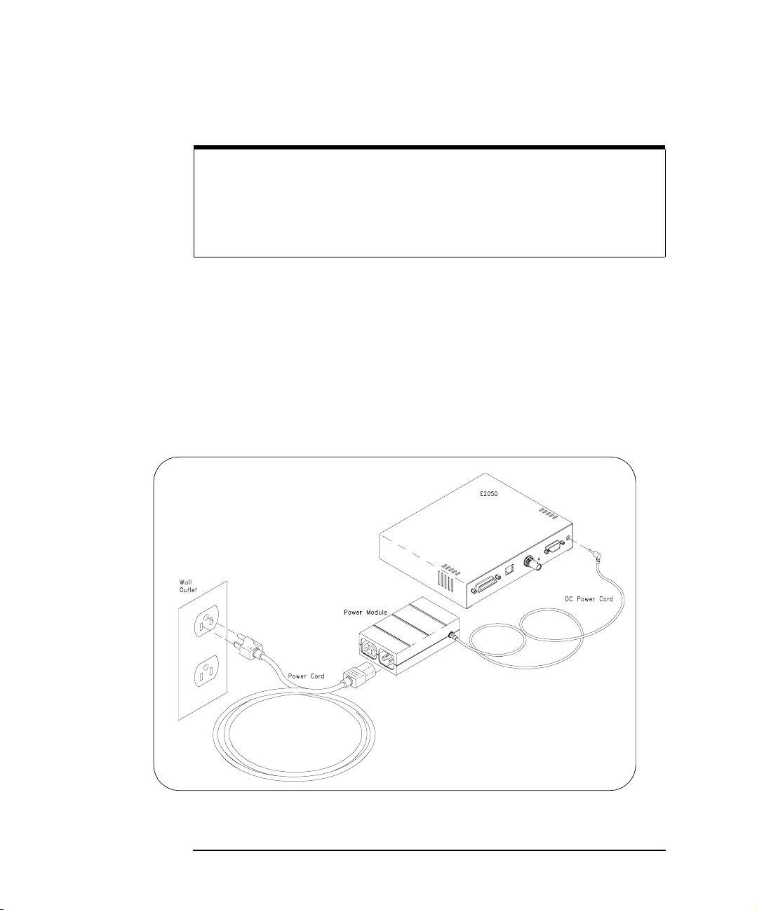
Step 4: Connect GPIB Cable and Power Cords
NOTE
The power module and Gateway do not have power switches.
Connecting the standard AC power cord to the power source (wall outlet)
activates both units. The power module automatically adapts to the
correct AC voltage range for your power source.
n Connect the GPIB cable from the GPIB instrument(s) to the GPIB
connector on the back panel of the Gateway.
n Connect the DC power cord attached to the power module (AC/DC
Adapter) to the power input on the back panel of the Gateway, as
shown.
n Connect the standard AC power cord to AC IN on the power module
and to a power outlet (wall outlet), as shown.
Connecting the Power Module
30 Chapter 2
Page 31

Installing the Hardware
Step 5: Observe the Power-On Sequence
n The Gateway now goes through its power-on, hardware self-test.
Verify that the hardware is working properly by looking at the LEDs
on the front panel of the Gateway.
n The green Power LED should now be illuminated and the red Fault
LED should be off. One or more of the yellow LAN LEDs may also
be flashing. Ignore the LAN LEDs at this time.
n The red Fault LED is illuminated briefly at power-on to verify its
operation. If the
found during the power-on, hardware self-test of the Gateway.
Please contact Agilent Technologies for instructions. Service is
required only if the
Fault LED remains illuminated, a hardware fault was
Fault LED remains illuminated.
n Once you have verified that the hardware is working properly (the
Gateway’s green
standard AC power cord from the power outlet (wall outlet).
Power LED is illuminated), disconnect the
Installation
Chapter 2 31
Page 32

Notes:
Installation
Installing the Hardware
32 Chapter 2
Page 33

3
Configuration
33
Page 34

Configuration
This chapter gives guidelines to configure the E2050 LAN/GPIB Gateway on
your network. You can use this chapter if you are configuring the Gateway
for the first time on your network or if you need to change the Gateway’s
configuration.
NOTE
If the E2050 LAN/GPIB Gateway is already configured and you want to
change the configuration, see “Configuring the Gateway” in Chapter 4
first. Then, use this chapter to reconfigure the Gateway.
This chapter includes:
n Setting Configuration Values
n Using Configuration Methods
34 Chapter 3
Page 35

Configuration
Setting Configuration Values
Setting Configuration Values
This section gives guidelines to set E2050 configuration values, including:
n Steps to Set Configuration Values
n Configuration Values Descriptions
n Default Configuration Settings
n How Configuration Values are Used
Steps to Set Configuration Values
To configure an E2050 LAN/GPIB Gateway on a network, you will need to:
n Know the configuration values that can be used for the Gateway,
including the defaults (if any) that are preset for each configuration
value.
n Decide which configuration values you will need to change or set for
the Gateway.
n Use one of three configuration methods on HP-UX or use the Telnet
configuration method on Windows 95, Windows 98, Windows 2000,
Windows Me or Windows NT to change or set desired configuration
values for the Gateway.
Configuration Values Descriptions
This section provides a brief description of the configuration values that are
used to configure the E2050 LAN/GPIB Gateway on a network.
The most important configuration value is the Internet Protocol (IP) address
of the LAN/GPIB Gateway. Without a proper IP address, the Gateway may
not respond or may operate unexpectedly.
At a minimum, you must set the IP address for the LAN/GPIB Gateway on
your network. In fact, the IP address may be the only configuration value you
will need to set. To determine what configuration values other than the IP
address (if any) you will need for the Gateway, see this section and the
“Default Configuration Settings” section.
Chapter 3 35
Page 36

Configuration
Setting Configuration Values
NOTE
IP addresses for network devices are assigned by a designated Network
Administrator in your workplace. If you are not the Network Administrator,
you will need to contact the designated Network Administrator who can
assign the Gateway’s IP address for you.
The following table describes the configuration values for the E2050 and the
applicable default (factory-set) values. The E2050 LAN/GPIB Gateway is
shipped from the factory with default settings for the configuration values
listed in the table. You can use the methods described in “Using
Configuration Methods” to change or set any of the configuration values as
needed.
The E2050 LAN/GPIB Gateway uses these default configuration values
until you explicitly change any value of these values and set any other
configuration values. The Gateway also uses these values when you press
the Gateway’s
Config Preset button (on the back panel of the Gateway).
Value Default Value Description
BOOTP ON/OFF ON This value is used to enable (ON) or disable (OFF) a BOOTP
or a BOOTP with TFTP configuration of the LAN/GPIB
Gateway. This value is only used with the Telnet configuration
method.
Default Subnet
Gateway Address
Hardware Address
(MAC)
0.0.0.0 This value is the IP address of the default subnet gateway
that allows the E2050 LAN/GPIB Gateway to communicate
with systems that are not on the local subnet.
Thus, this is the default subnet gateway where packets are
sent which are destined for a device not on the local subnet,
as determined by the subnet mask setting. Only one default
subnet gateway can be configured. A value of 0.0.0.0
indicates that no subnetting is to be done.
N/A This value is the unique address of the LAN interface in the
LAN/GPIB Gateway. (The LAN hardware address is also often
called the link-level address, the Ethernet station address, or
the LANIC ID.) The LAN hardware address is printed on a label
on the underside of the LAN/GPIB Gateway box.
36 Chapter 3
Page 37

Setting Configuration Values
Value Default Value Description
Configuration
Hardware Address
(MAC) (cont’d)
Hostname E2050 This value configures the Internet domain name for the LAN/
HP-IB Address
HP-IB Interface
Name
HP-IB Logical Unit
I/O Timeout 120 sec This value sets the server I/O timeout in seconds. It configures
N/A The hardware address value cannot be set or changed with
Telnet configuration of the LAN/GPIB Gateway. However, the
hardware address value must be specified and set when using
the BOOTP or the BOOTP with TFTP configuration method.
GPIB Gateway. This name is used in some error and status
messages, but is not a required configuration setting. The
maximum length of the hostname value is 35 characters.
21
hpib
7
This value configures the GPIB bus address. This address is
used when transfers are made on the GPIB bus. A SICL client
application can change this value by using the SICL function
IGPIBBUSADDR. The GPIB address value can be any number
0 through 30.
This value is the symbolic name of the GPIB interface in the
LAN/GPIB Gateway. It is used in a SICL client application’s
iopen operation to symbolically reference the GPIB interface
in the Gateway. The maximum length of the GPIB interface
name is 15 characters.
If VXI-11 (TCP/IP Instrument Protocol) is used, the name must
be changed to gpib0. Also, for VISA LAN client, this name
must match the name set in the IO Config utility.
This value is the interface logical unit number of the GPIB
interface in the LAN/GPIB Gateway. It may be used in a SICL
client application’s iopen statement to uniquely identify the
GPIB interface in the Gateway. The GPIB logical unit value can
be any number 1 through 255.
the Gateway to use an I/O timeout of the specified amount of
seconds if the client requests a timeout of infinity. If 0 is
specified for this value and the client requests infinity, the
Gateway will use a timeout of infinity as requested.
This timeout value may be used to ensure that the Gateway
does not wait indefinitely for an I/O operation. It also allows the
Gateway to detect certain network events (such as when a
client connection is dropped) that may otherwise go
undetected. If the Gateway detects such a condition, it will
release any resources, such as locks, associated with the
client.
Chapter 3 37
Page 38

Configuration
Setting Configuration Values
Value Default Value Description
IP Address 192.0.0.192 This value is the Internet Protocol (IP) address of the
LAN/GPIB Gateway. The IP address is a required value and
is used for all IP and TCP/IP communications with the
LAN/GPIB Gateway.
The IP address is represented in dotted decimal notation
(for example, 154.140.222.201). This number is not
assigned by Agilent. Rather, it is assigned by your designated
Network Administrator. The LAN/GPIB Gateway uses the
default IP address of 192.0.0.192 as a temporary IP
address until you configure a true IP address.
IP Allow List
* (all allowed)
The IP allow list defines a list of computer systems that are
allowed to communicate with the LAN/GPIB Gateway. When a
computer system attempts to connect to the LAN/GPIB
Gateway, the Gateway checks the IP address of the computer
system requesting the connection against the list of IP
addresses that are allowed access to the LAN/GPIB Gateway.
The IP address(es) of the computer system(s) are represented
in dotted decimal notation, with each IP address separated by
a blank space. The maximum length of the allow list is 125
characters. Not specifying an allow list or specifying an allow
list value of * (the asterisk wild card character) allows
connections from all computer systems on the network.
An example IP allow list entry follows that lists the specific
IP addresses of two computer systems that are allowed to
communicate with the LAN/GPIB Gateway:
allow: 156.140.34.2 192.54.24.5
You can also use the asterisk wild card character (*) to
signify all IP addresses. For example, either of the following
entries allow all computer systems with IP addresses starting
with 156.140:
allow: 156.140.*.* or allow: 156.140.*
In addition, you can use a dash character (-) between
numbers to signify a range of IP addresses. For example:
allow: 156.140.34-48.2 192.54.24-37.*
38 Chapter 3
Page 39

Configuration
Setting Configuration Values
Value Default Value Description
LAN Timeout 0 sec This value sets the LAN connect timeout in seconds. The
Gateway may use the TCP keepalive timer of the TCP/IP
protocol stack to determine if a client is still reachable. By
specifying this configuration value, the Gateway turns on the
keepalive timer when connecting to the client.
If after the specified amount of time there has been no activity
on the connection, the Gateway will send keepalive probes to
the client to determine if it is still alive. After a system specified
amount of time, the connection will be marked as down
(“dropped”), and the Gateway will release any resources which
were allocated to the associated client.
A value of 0 means no timeout is set. Thus, the Gateway will
wait forever and no keepalive probes are sent. If this value is
set, it is recommended that the largest value be used which still
meets the application’s need for unreachable client detection.
Smaller LAN timeout values will generate keepalive probes
(network traffic) more often than larger values in an otherwise
idle but healthy system, using more of the available network
bandwidth.
Subnet Mask 0.0.0.0 This value is used to enable the LAN/GPIB Gateway to
determine if an IP address is on the same local subnet as
the LAN/GPIB Gateway itself.
When an address is on a different subnet, all packets must be
sent to a subnet gateway. The subnet mask is sometimes not
needed with subnet gateways, which automatically know when
to forward packets between subnets. A value of 0.0.0.0 or
255.255.255.255 indicates no subnetting is to be done.
Syslog Server
Address
0.0.0.0 This value, which is only available on HP-UX (not on Windows
95/98/2000/Me/NT), is the IP address of the syslog server to
which you want the LAN/GPIB Gateway to send syslog
messages.
Syslog messages identify changes in the LAN/GPIB Gateway’s
status or error conditions that have occurred. A syslogd
daemon on the syslog server reads and forwards messages
to a log file.
Chapter 3 39
Page 40

Configuration
Setting Configuration Values
Value Default Value Description
Syslog Server
Address (cont’d)
TFTP File N/A This value is the path to an optional, TFTP configuration file.
0.0.0.0 Typ icall y, syslogd obtains its routing information from the /
etc/syslog.conf configuration file, which you can edit to
specify the log file to which you want syslog messages from the
LAN/GPIB Gateway routed. See syslogd(1M) for more
information on the syslogd daemon and the syslog.conf
file.
The syslog server’s IP address is represented in dotted
decimal notation. This is not a required configuration setting.
However, setting up a syslog server and log file is
recommended, as syslog messages are helpful in
administering the LAN/GPIB Gateway and troubleshooting
problems with the Gateway.
This value is only used with the BOOTP with TFTP
configuration of the LAN/GPIB Gateway.
The TFTP file contains additional configuration values,
including LAN timeout, I/O timeout, IP allow list, GPIB address,
GPIB interface name, and/or GPIB logical unit. The maximum
length of the path to the TFTP file is 33 characters. The TFTP
file name is usually designated with a .cfg extension.
There are two modes for running TFTP: one which uses the
TFTP home directory (the default mode) and one where a path
is specified on the TFTP command line (the command line is
normally set in the /etc/inetd.conf file on both HP-UX
Versions 9 and 10.01).
If no path is specified on the command line (the default mode),
a relative path from the home directory must be used. In this
case, the path to the TFTP configuration file is relative either
from the /usr/tftpdir directory on HP-UX Version 9 or
from the /home/tftpdir directory on HP-UX Version 10.01.
However, if a path is specified on the command line, the full
path to the TFTP configuration file must be used.
40 Chapter 3
Page 41

Configuration
Setting Configuration Values
How Configuration Values are Used
The E2050 LAN/GPIB Gateway uses the default configuration values and/or
the configuration values that you changed or set depending on certain
situations, such as when the power is cycled on the Gateway or when the
Config Preset button on the back panel of the Gateway is pressed.
This section summarizes how configuration values are used in various
situations. This information can help you better maintain the Gateway and
more easily troubleshoot problems you may encounter with the Gateway.
This section also describes how the Gateway uses the configuration values
during the Gateway’s power-on initialization sequence (after power is cycled
on the Gateway) and when the Gateway’s
Config Preset button is pressed.
During the Power-on
Initialization
Sequence
After Telnet
Configuration
Prior to Successful
Configuration with
BOOTP or BOOTP
with TFTP
After BOOTP or
BOOTP with TFTP
Configuration
When power is applied to the Gateway and the hardware self-test has
completed, the networking subsystem is initialized. What happens during
this initialization sequence depends on what configuration method, if any,
has been used to configure the Gateway.
If you have used the Telnet configuration method to set the IP address, the
Gateway will not send BOOTP requests at power-on to configure itself.
Instead, the Gateway will simply use the IP address and any other
configuration values that were set through Telnet.
If you are applying power to the Gateway before it has been successfully
configured with an actual IP address via BOOTP or BOOTP with TFTP, the
Gateway will send BOOTP requests to the BOOTP server for up to five
minutes. When the BOOTP server’s bootpd daemon receives the request,
it will search the /etc/bootptab configuration file for an entry that
matches the Gateway’s LAN hardware address.
When a match is found, bootpd retrieves the configuration data associated
with the entry and sends it to the Gateway as a BOOTP response. The
Gateway then completes its initialization using the configuration data
provided in the BOOTP response.
If you have applied power to the Gateway one or more times since
configuration, the Gateway will have successfully completed BOOTP
requests in the past. Thus, the Gateway will send BOOTP requests for only
one minute before it stops and then uses the previous BOOTP response
stored in the Gateway’s non-volatile memory.
Chapter 3 41
Page 42

Configuration
Setting Configuration Values
When the Config
Preset Button is
Pressed
The recessed Config Preset button on the back panel of the Gateway is used
to reset the LAN/GPIB Gateway to its default configuration values (preset at
the factory). The
Config Preset button has two modes of operation.
n If you press the Config Preset button at the same time as you apply
power to the Gateway, all previous configuration information is
erased and all default configuration values are used.
This is helpful if you want to completely reconfigure the Gateway,
but you first need to set the Gateway to a known state (to a state
where the Gateway is using all of its default configuration values).
n If you press the Config Preset button after power is applied, previous
configuration information is not erased, but the Gateway temporarily
uses its default IP address. That is, only the IP address is reset to its
default value temporarily. Once you reboot or cycle the power again,
the Gateway will return to its actual IP address that was previously
set.
This is helpful if you want to interrogate the Gateway at a known
address in preparation for setting a new IP address for the Gateway.
However, all network connections to the Gateway, if any, are also
terminated without any cleanups.
NOTE
If you use the default IP address, you may need to explicitly tell your
networking software how to talk to the Gateway. This is because the
default IP address may appear to be on a different subnet. Use the
route command, as follows.
• On HP-UX client systems, as root:
route add host 192.0.0.192 your_system_name
• On Windows 95/98/2000/Me/NT client systems:
route add 192.0.0.192 your_system_name
42 Chapter 3
Return
Enter
Page 43

Configuration
Configuration Methods
Configuration Methods
This section describes configuration methods you can use to set the
configuration values for the E2050 LAN/GPIB Gateway, including:
n Configuration Methods Overview
n Using Telnet Configuration Method (Windows)
n Using Telnet Configuration Method (HP-UX)
n Using BOOTP Configuration (HP-UX)
n Using BOOTP with TFTP Configuration Method (HP-UX)
Configuration Methods Overview
Summary descriptions of the three methods to configure an E2050
LAN/GPIB Gateway on a network follow.
NOTE
If you configure the Gateway on your network from a
Me/NT Client System,
Neither the BOOTP nor the BOOTP with TFTP configuration methods
are available on Windows 95/98/2000/Me/NT.
If you configure the Gateway on your network from an
System,
you can use any one of the three configuration methods.
you must use the Telnet configuration method.
Windows 95/98/2000/
HP-UX Client
Te ln e t Teln et is a networking protocol that connects to the Gateway and then
provides a command line interface to assist you in configuring the Gateway
on the network. If you prefer to use a command line interface (rather than
having to edit files, as you would in the BOOTP and the BOOTP with TFTP
methods), you may want to choose this method to configure the Gateway on
the network. You can use Telnet from either an HP-UX or a Windows 95/98/
2000/Me/NT client system to set or change any of the configuration values
for the Gateway.
The Telnet utility used to configure the LAN/GPIB Gateway is also used to
administer the Gateway after it has been configured on the network. For
example, you can use the Telnet utility to monitor the status of client
connections, etc. Thus, you may want to use the Telnet configuration
method because you will be using the same Telnet utility in the future for
administration tasks.
Chapter 3 43
Page 44

Configuration
Configuration Methods
BOOTP BOOTP is a bootstrap protocol that allows critical configuration values such
as the IP address and subnet mask to be set easily. With the BOOTP
configuration method, you set the values for the Gateway in the
/etc/bootptab file. This file is then used by the bootpd daemon running
on the BOOTP server to configure the Gateway on the network. You can use
BOOTP from an HP-UX client system if you do not need to change the
default values for the following configuration values:
n LAN timeout
n I/O timeout
n IP allow list
n GPIB address
n GPIB interface name
n GPIB logical unit
NOTE
If you use the BOOTP method, the BOOTP server system must be
configured to run the bootpd daemon. See the Administering ARPA
Services manual for more information.
BOOTP
with TFTP
Trivial File Transfer Protocol (TFTP) is a protocol that can be used with
BOOTP, where more configuration values for the Gateway are set in a
separate TFTP configuration file. The path to this TFTP configuration file,
which usually has a .cfg extension, is set in the T144: BOOTP tag in the
/etc/bootptab file.
Both the /etc/bootptab file and the TFTP configuration file contents are
used by the bootpd daemon running on the BOOTP server to configure the
Gateway on the network. You can use BOOTP with TFTP from an HP-UX
client system to set or change any of the configuration values for the
Gateway.
NOTE
If you use the BOOTP with TFTP method, the BOOTP and TFTP server
system must be configured to run the bootpd and tftpd daemons.
See the Administering ARPA Services manual for more information.
44 Chapter 3
Page 45

Configuration
Configuration Methods
Using Telnet Configuration Method (Windows)
To configure the LAN/GPIB Gateway on your network using the Telnet
configuration method from a Windows 95/98/2000/Me/NT client system:
1 Power-on the Gateway by plugging the AC power cord from the
power module into a power outlet (wall outlet).
2 Once the Gateway is powered on, press the
on the back panel of the Gateway. This causes the Gateway to
temporarily use its default IP address, 192.0.0.192. The
Conn
(LAN Connect) LED on the front panel of the Gateway will
flash slowly, showing that the default IP address is now in use.
3 If not already running, start Windows 95/98/Me or Windows
2000/NT on the client computer system (the Windows PC).
4 From the Windows 95/98/Me task bar at the bottom of the screen,
select Start | Programs | MS-DOS Prompt. The MS-DOS window
opens. Or, from the Windows 2000/NT Program Manager, select
Main. Then select MS-DOS Prompt. The MS-DOS window opens.
5 At the > prompt in the MS-DOS window, type:
Config Preset button
LAN
route add 192.0.0.192 your_system_name Enter
This sets up a route table entry on your client system for the
Gateway at its default IP address.
6 At the > prompt in the MS-DOS window, type:
telnet 192.0.0.192
This connects you to the Gateway at its temporary (default) IP
address and the Telnet window opens.
Enter
NOTE
If you are unable to make a Telnet connection using the default IP
address (192.0.0.192), try pressing the
then try the telnet command (Step 6). If you are still unsuccessful, see
Chapter 5.
Chapter 3 45
Config Preset button again and
Page 46

Configuration
Configuration Methods
When you are connected to the Gateway, you will see general
information about the Telnet utility commands, as well as a listing of
the current configuration settings for this Gateway.
For example, if you have not changed any of the configuration
settings previously, you will see the default configuration settings for
the Gateway as shown. In this display, the hardware-addr: value
is an example. Your hardware-addr: value will be correct for your
Gateway.
Welcome to the E2050 LAN/GPIB Gateway configuration utility.
Commands
?
exit, quit
reboot
status
Configuration Parameters
hostname:
hardware-addr:
ip:
default-gw:
subnet-mask:
syslog-svr:
bootp:
lan-timeout:
io-timeout:
allow:
hpib-address:
hpib-name:
hpib-unit:
7 Now you must turn on
Show additional commands
Exit WITHOUT saving configuration changes
Save configuration changes and restart
Show the LAN/GPIB Gateway connection status
E2050
0800091A0E02
0.0.0.0
0.0.0.0
0.0.0.0
0.0.0.0
ON
0
120
*
21
hpib
7
Local Echo in the Terminal Preferences dialog
# Internet domain name
# Ethernet station address
# Internet Protocol address
# Default subnet gateway IP address
# Network subnet mask
# Syslog server IP address
# Obtain config via BOOTP/TFTP
# LAN connect timeout in seconds
# Server I/O timeout in seconds
# IP allow list
# GPIB Address
# GPIB interface symbolic name
# GPIB logical unit number
box so the Telnet utility will display your typed input. From the menu
at the top of the Telnet window, select
Terminal Preferences dialog box is displayed.
Terminal | Preferences. The
8 Click the checkbox next to
displayed in the checkbox.
9Click
OK to close the Terminal Preferences dialog box.
Local Echo to turn it on. A checkmark is
Local Echo is now set on.
46 Chapter 3
Page 47

Configuration
Configuration Methods
10 At the Telnet prompt (>), enter the configuration values you want to
change or set. (You only need to specify the non-default values that
you want.) The following information will help you set the values
correctly.
The following table lists the configuration values you can set using
Telnet. The following information shows the syntax you should use
and provides tips to help you to change or set the configuration
values correctly.
NOTE
By using the Telnet configuration method, the LAN hardware address
(hardware-addr:) value is automatically set to the correct hardware
address for this LAN/GPIB Gateway. Do not change the hardware
address value via Telnet. Its value in the Telnet configuration table is for
information purposes only.
Configuration Value Telnet Command Default Value
Hostname hostname: E2050
IP Address ip: 192.0.0.192
Default Subnet Gateway Address gateway: 0.0.0.0
Subnet Mask subnet-mask: 0.0.0.0
Syslog Server Address syslog-svr: 0.0.0.0
BOOTP bootp: ON
LAN Timeout lan-timeout: 0
I/O Timeout io-timeout: 120
IP Allow List allow: * (All allowed)
GPIB Address hpib-address: 21
GPIB Interface Name hpib-name:
GPIB Logical Unit hpib-unit: 7
1
Change name to gpib0 for VXI-11 compatibility
hpib
1
Chapter 3 47
Page 48

Configuration
Configuration Methods
For each configuration value to change or set, use the syntax:
Telnet_command: value
value of 156.140.222.201 for the Gateway, enter:
ip: 156.140.222.201
If you make a mistake, re-enter the correct configuration value you
want. To do this, use the same syntax as before to re-enter the
value (Telnet_command: value
If you want to exit without saving any of the configuration values you
have changed or set, enter either exit
can then re-enter the Telnet configuration utility starting with Step 6.
Enter. For example, to set the IP address
Enter
Enter).
Enter or quit Enter. You
Any time during the Telnet session, you can enter config
Enter to
view the current configuration settings. Any time during the Telnet
session, you can enter ?
Enter for a list of available commands you
can use in the Telnet utility.
11 When you have changed or set all the configuration values you want
for the Gateway, type reboot
Enter. Then, type y Enter to confirm
your changes. Rebooting activates the configuration values you
have set for the Gateway.
CAUTION
If you are reconfiguring the Gateway, any client operations in progress
and client connections will be terminated by the reboot command.
12 After you have rebooted the Gateway, test that the Gateway has
been successfully configured by using the ping command. This
command allows you to test general network connectivity between
your client computer system and the LAN/GPIB Gateway. At the
client system, type: ping hostname (or) IP_address
Enter
For example, using a Gateway’s hostname:
ping E2050.agilent.com
Enter
Or, using a Gateway’s IP address:
ping 156.140.4.249
Enter
48 Chapter 3
Page 49

Configuration
Configuration Methods
You should get a response from the ping command that is similar to
the following, where each line after the
PING line is an example of a
packet successfully reaching the Gateway from the client system.
If the
ping response is similar to the following, the Gateway has
been configured successfully.
Pinging E2050.agilent.com[128.10.0.3] with 32 bytes
of data:
Reply from 128.10.0.3:bytes=32 time=10ms TTL=255
Reply from 128.10.0.3:bytes=32 time=10ms TTL=255
Reply from 128.10.0.3:bytes=32 time=10ms TTL=255
.
.
.
However, if
ping is unable to reach the host, you will see a message
similar to the following. This indicates the client was unable to
contact the Gateway and there may be some problem with the
Gateway’s configuration or with the network itself.
configuring the Gateway or want to verify that the configuration is correct,
see Chapter 5.
If you have trouble
Pinging E2050.agilent.com[128.10.0.3] with 32 bytes
of data:
Request timed out.
Request timed out.
Request timed out.
Chapter 3 49
Page 50

Configuration
Configuration Methods
Using Telnet Configuration Method (HP-UX)
To configure the LAN/GPIB Gateway on your network using Telnet from an
HP-UX client system, do the following:
1 Power-on the Gateway by plugging the AC power cord from the
power module into a power outlet (wall outlet).
2 After the Gateway is powered on, press the recessed
button on the back panel of the Gateway. This causes the Gateway
to temporarily use its default IP address, 192.0.0.192. The
Conn
(LAN Connect) LED on the front panel of the Gateway will
flash slowly, showing that the default IP address is now in use.
3 Log into a client computer system (the Series 700 HP-UX
workstation) as root.
4 At the system prompt, type:
route add host 192.0.0.192
This sets up a route table entry on your client system for the Gateway
at its default IP address.
5 At the system prompt, type:
telnet 192.0.0.192
This connects you to the Gateway at its temporary, default IP
address.
NOTE
Return
your_system_name Return
Config Preset
LAN
If you are unable to make a Telnet connection using the default IP
address (192.0.0.192), try pressing the
and then try the telnet command (Step 5). If you are still unsuccessful,
see Chapter 5.
When you are connected to the Gateway, you will see the message:
Connected to 192.0.0.192. This is followed by general information
about the Telnet utility commands and a listing of the current configuration
settings for this Gateway.
50 Chapter 3
Config Preset button again
Page 51

Configuration
Configuration Methods
For example, if you have not changed any of the configuration settings
previously, you will see the default configuration settings for the Gateway, as
follows. In this display, the hardware-addr: value is an example. Your
hardware-addr: value will be correct for your Gateway.
NOTE
On HP-UX 10.01, you may see the string Local flow control off at
the bottom of the screen. This will not affect the use of the Telnet utility to
configure the E2050.
Welcome to the E2050 LAN/GPIB Gateway configuration utility.
Commands
?
exit, quit
reboot
status
Configuration Parameters
hostname:
hardware-addr:
ip:
default-gw:
subnet-mask:
syslog-svr:
bootp:
lan-timeout:
io-timeout:
allow:
hpib-address:
hpib-name:
hpib-unit:
Show additional commands
Exit WITHOUT saving configuration changes
Save configuration changes and restart
Show the LAN/GPIB Gateway connection status
E2050
0800091A0E02
0.0.0.0
0.0.0.0
0.0.0.0
0.0.0.0
ON
0
120
*
21
hpib
7
# Internet domain name
# Ethernet station address
# Internet Protocol address
# Default subnet gateway IP address
# Network subnet mask
# Syslog server IP address
# Obtain config via BOOTP/TFTP
# LAN connect timeout in seconds
# Server I/O timeout in seconds
# IP allow list
# GPIB Address
# GPIB interface symbolic name
# GPIB logical unit number
6 At the Telnet prompt (>), enter the configuration values you want to
change or set. You only need to specify the non-default values that
you want. The following information will help you set the values
correctly.
Chapter 3 51
Page 52

Configuration
Configuration Methods
The following table lists the configuration values you can set using
Telnet. The information following the table explains the syntax you
should use and provides reminders to help you to change or set the
configuration values correctly.
NOTE
By using the Telnet configuration method, the LAN hardware address
(hardware-addr:) value is automatically set to the correct hardware
address for this LAN/GPIB Gateway. Do not change the hardware
address value via Telnet. Its value in the Telnet configuration table is for
information purposes only.
Configuration Value Telnet Command Default Value
Hostname hostname: E2050
IP Address ip: 192.0.0.192
Default Subnet Gateway Address gateway: 0.0.0.0
Subnet Mask subnet-mask: 0.0.0.0
Syslog Server Address syslog-svr: 0.0.0.0
BOOTP bootp: ON
LAN Timeout lan-timeout: 0
I/O Timeout io-timeout: 120
IP Allow List allow: * (All allowed)
GPIB Address hpib-address: 21
GPIB Interface Name hpib-name: hpib
GPIB Logical Unit hpib-unit: 7
For each configuration value to change or set, use the syntax:
Telnet_command: value Return
For example, to set the IP address value of 156.140.222.201 for
the Gateway, enter: ip: 156.140.222.201
Return
If you make a mistake, re-enter the correct configuration value you
want. To do this, use the same syntax as before to re-enter the
value (Telnet_command: value
Return).
52 Chapter 3
Page 53

Configuration
Configuration Methods
If you want to exit without saving any of the configuration values you
have changed or set, enter either exit
Return or quit Return. You
can then re-enter the Telnet configuration utility starting with Step 5.
Any time during the Telnet session, you can enter config
Return to
view the current configuration settings. Any time during the Telnet
session, you can enter ?
Return for a list of available commands you
can use in the Telnet utility.
7 When you have changed or set all the configuration values you want
for the Gateway, type reboot
Return. Then, type y Return to
confirm your changes. Rebooting activates the configuration values
you have set for the Gateway.
CAUTION
If you are reconfiguring the Gateway, any client operations in progress
and client connections will be terminated by the reboot command.
8 After you have rebooted the Gateway, test that the Gateway has
been successfully configured by using the ping command. This
command allows you to test general network connectivity between
your client computer system and the LAN/GPIB Gateway. At the
client system, type: ping hostname (or) IP_address
Return
For example, using a Gateway’s hostname:
ping E2050.agilent.com Return
Or, using a Gateway’s IP address:
ping 156.140.4.249
Return
You should get a response from the ping command that is similar to
the following, where each line after the
PING line is an example of a
packet successfully reaching the Gateway from the client system.
If the ping response is similar to the following, the Gateway has
been configured successfully. If, after several seconds, ping does
not print any lines, use
Ctrl+C to kill ping. The ping will then report
on what it found.
Chapter 3 53
Page 54

Configuration
Configuration Methods
PING E2050.agilent.com: 64 byte packets
64 bytes from 128.10.0.3: icmp_seq=0. time=3. ms
64 bytes from 128.10.0.3: icmp_seq=1. time=3. ms
64 bytes from 128.10.0.3: icmp_seq=2. time=2. ms
.
.
.
A response similar to the following indicates the client was unable
to contact the Gateway. There may be some problem with the
Gateway’s configuration or with the network itself. If you have
trouble configuring the Gateway or want to verify that the
configuration is correct, see Chapter 5.
----E2050.agilent.com PING Statistics---4 packets transmitted, 0 packets received, 100%
packet loss
54 Chapter 3
Page 55

Configuration
Configuration Methods
Using BOOTP Configuration Method (HP-UX)
To configure a LAN/GPIB Gateway on your network using BOOTP from an
HP-UX client system:
1 Make sure that the Gateway is powered-off. The AC power cord
from the power module must be disconnected from the power outlet
(wall outlet).
2 Determine which computer system is the BOOTP server on your
network. Then, log into the BOOTP server system as root.
Edit the /etc/bootptab configuration file. Add an entry to the file
for each LAN/GPIB Gateway on your network. (You only need to
specify the non-default values that you want.) The following
information will help you complete the entry correctly.
The following table lists the values you can configure. In the table,
BOOTP Tag is the tag that the BOOTP daemon (bootpd) searches
for in the /etc/bootptab file to service BOOTP requests. See the
next example BOOTP entry and tips to help you complete your
BOOTP entry correctly.
For more information on the BOOTP tags, use the system man
command on bootpd. Also, see “Configuration Values” for more
information about each of the configuration values.
Configuration Value BOOTP Tag Default Value
Hostname hn E2050
Hardware Address ha None
IP Address ip 192.0.0.192
Default Subnet Gateway Address gw 0.0.0.0
Subnet Mask sm 0.0.0.0
Syslog Server Address lg 0.0.0.0
Chapter 3 55
Page 56

Configuration
Configuration Methods
This example BOOTP entry configures a hostname (hn), a
hardware address (ha), and an IP address (ip) for the LAN/GPIB
Gateway. All other configuration values are “set” to (will default to)
the factory defaults
E2050:\ Hostname for this Gateway
hn:\
ht=ether:\ Hardware type, which should be ether
vm=rfc1048:\ Vendor magic cookie selector, which should
ha=0800091A0E00:\ Hardware address for the Gateway’s LAN
ip=156.140.4.249 IP address for the Gateway
.
be rfc1048
interface
For each entry you make to the file, include a colon (“:”) and a
backslash (“\”) after each field to continue the entry on the next line.
(Do not put the :\ at the end of the last field in your entry.)
Begin the hostname with a letter. Do not start a hostname with any
other character, such as a number, underscore, etc. Use only
letters, numbers, periods, or hyphens within a hostname. The
underscore character (“_”) is not allowed.
The LAN hardware address (ha) value is the address you recorded
while installing the Gateway hardware in Chapter 2. The Gateway’s
LAN hardware address is printed on a label on the underside of the
Gateway box.
The IP address (ip) value is the address that your designated
Network Administrator assigned for the Gateway. The address must
be in dotted decimal notation.
3 Once you have added the configuration values for each of your
Gateways, save and close the /etc/bootptab file. Then, power
on the Gateway by plugging-in the power cord to the power outlet
(wall outlet).
As soon as it completes its hardware self-test, the Gateway will
begin sending BOOTP requests to the BOOTP server. While the
Gateway is sending BOOTP requests, the
LAN Conn (LAN Connect)
LED on the front panel of the Gateway will flash rapidly. The BOOTP
server should respond with the BOOTP response to configure the
Gateway. When the Gateway receives a valid response from the
BOOTP server, the
LAN Conn LED will stop flashing.
56 Chapter 3
Page 57

Configuration
Configuration Methods
4 Test that the Gateway has received the BOOTP response and has
configured itself by using the ping command. This command allows
you to test general network connectivity between your client
computer system and the LAN/GPIB Gateway. At the client system,
type: ping hostname (or) IP_address
Enter.
For example, using a Gateway’s hostname:
ping E2050.agilent.com
Enter
Or, using a Gateway’s IP address:
ping 156.140.4.249
Enter
You should get a response from the ping command that is similar to
the following, where each line after the PING line is an example of a
packet successfully reaching the Gateway from the client system. If
your
ping response is similar to the following, the Gateway has been
configured successfully.
PING E2050.agilent.com: 64 byte packets
64 bytes from 128.10.0.3: icmp_seq=0. time=3. ms
64 bytes from 128.10.0.3: icmp_seq=1. time=3. ms
64 bytes from 128.10.0.3: icmp_seq=2. time=2. ms
.
.
.
If, after several seconds, ping does not print any lines, use
to kill ping. The ping will then report on what it found. A response
similar to the following indicates the client was unable to contact the
Gateway and there may be some problem with the Gateway’s
configuration or with the network itself. If you have trouble
configuring the Gateway or want to verify that the configuration is
correct, see Chapter 5.
Ctrl+C
----E2050.agilent.com PING Statistics---4 packets transmitted, 0 packets received, 100%
packet loss
Chapter 3 57
Page 58

Configuration
Configuration Methods
Using BOOTP with TFTP Configuration Method (HP-UX)
To configure a LAN/GPIB Gateway on your network using BOOTP with
TFTP from an HP-UX client system:
1 Make sure that the Gateway is powered OFF. The AC power cord
from the power module must be disconnected from the power outlet
(wall outlet).
2 Determine which computer system is the BOOTP server on your
network. Then, log into the BOOTP server system as root.
3 Edit the /etc/bootptab configuration file. Add an entry to the file
for each LAN/GPIB Gateway on your network. (You only need to
specify the non-default values that you want.) The following
information will help you complete the entry correctly.
The following table lists the values you can configure. In the table,
BOOTP Tag is the tag that the BOOTP daemon (bootpd) searches
for in the /etc/bootptab file to service BOOTP requests. An
example BOOTP entry and tips are provided to help you complete
your BOOTP entry correctly.
For more information on the BOOTP tags, use the system man
command on bootpd. Also, see “Configuration Values” for more
information about each of the configuration values.
Configuration Value BOOTP Tag Default Value
Hostname hn E2050
Hardware Address ha None
IP Address ip 192.0.0.192
Default Subnet Gateway Address gw 0.0.0.0
Subnet Mask sm 0.0.0.0
Syslog Server Address lg 0.0.0.0
TFTP File T144 None
58 Chapter 3
Page 59

Configuration
Configuration Methods
This example BOOTP entry configures a hostname (hn), a
hardware address (ha), an IP address (ip), and the path to the
TFTP configuration file (T144). In this example, the path to the
TFTP configuration file is relative, with the assumption that the
default TFTP mode is being used. All other configuration values are
“set” to (will default to) the factory defaults.
E2050:\ Hostname for this Gateway
hn:\
ht=ether:\ Hardware type, which should be ether
vm=rfc1048:\ Vendor magic cookie selector, which should
be rfc1048
ha=0800091A0E00:\ Hardware address for the Gateway’s LAN
interface
ip=156.140.4.249:\ IP address for the Gateway
T144=”E2050/gw1.cfg” Path to the TFTP configuration file
For each entry you make to the file, include a colon (“:”) and a
backslash (“\”) after each field to continue the entry on the next line.
Do not put the :\ at the end of the last field in your entry.
Begin the hostname with a letter. Do not start a hostname with any
other character, such as a number, underscore, etc. Use only
letters, numbers, periods, or hyphens within a hostname. The
underscore character (“_”) is not allowed.
The LAN hardware address (ha) value is the address you recorded
while installing the Gateway hardware in Chapter 2. The Gateway’s
LAN hardware address is printed on a label on the underside of the
Gateway box.
The IP address (ip) value is the address that your designated
Network Administrator assigned for the Gateway. The address must
be in dotted decimal notation.
The TFTP configuration file (T144) value is the path to the TFTP file
you will use. (You will create the TFTP file in the following steps.)
The path must be enclosed in double quotation marks.
4 Once you have added the configuration values for each of your
Gateways, save and close the /etc/bootptab file.
Chapter 3 59
Page 60

Configuration
Configuration Methods
5 Create the appropriate directory structure and TFTP configuration
file for each LAN/GPIB Gateway, as noted in the T144 configuration
value you set in the /etc/bootptab file. Be sure you set
permissions on these directories and on the TFTP configuration file
to allow access by the bootpd daemon.
For example, the T144 value in the previous example /etc/
bootptab file was set to “E2050/gw1.cfg”. We will also assume
the default TFTP mode is being used and that the client system is
running HP-UX Version 9. Thus, in this example, you would:
n cd to the /usr/tftpdir directory.
n Create an E2050 subdirectory under /usr/tftpdir.
n cd to the E2050 subdirectory
n Create the TFTP configuration file, gw1.cfg, with your editor.
6 Edit the TFTP configuration file, adding the configuration values you
desire to set for the Gateway. (You only need to specify the nondefault values that you want.) The following information will help you
complete this file correctly.
This table lists the configuration values you can set in the TFTP file.
Also, see the example TFTP file that follows this table..
Configuration Value Telnet Command Default Value
Hostname hostname: E2050
LAN Timeout lan-timeout: 0
I/O Timeout io-timeout: 120
IP Allow List allow: * (All allowed)
GPIB Address hpib-address: 21
GPIB Interface Name hpib-name: hpib
GPIB Logical Unit hpib-unit: 7
60 Chapter 3
Page 61

Configuration
Configuration Methods
An example TFTP file follows. Consult your system documentation
for any other steps required to complete the TFTP configuration file.
# The E2050 gw1 Configuration File
hostname: E2050
# Timeouts
lan-timeout: 7200
io-timeout: 240
# IP allow list
allow: 156.140.34.2 15.2.*
# GPIB configuration
hpib-addr: 17
hpib-name: hpib1
hpib-unit: 8
7 Once you have added the configuration values you want, save and
close the TFTP configuration file(s).
8 Power on the Gateway by plugging-in the power cord to the power
outlet (wall outlet).
As soon as it completes its hardware self-test, the Gateway will
begin sending BOOTP requests to the BOOTP server. While the
Gateway is sending BOOTP requests, the
LAN Conn (LAN Connect)
LED on the front panel of the Gateway will flash rapidly.
The BOOTP server should respond with the BOOTP response to
configure the Gateway. When the Gateway receives a valid
response from the BOOTP server, the
LAN Conn LED will stop
flashing.
9 Test that the Gateway has received the BOOTP response and has
configured itself by using the
ping command. This command allows
you to test general network connectivity between your client
computer system and the LAN/GPIB Gateway.
Chapter 3 61
Page 62

Configuration
Configuration Methods
At the client system, type: ping hostname (or) IP_address Return
For example, using a Gateway’s hostname:
ping E2050.agilent.com
Or, using a Gateway’s IP address:
ping 156.140.4.249
You should get a response from the ping command that is similar
to the following, where each line after the PING line is an example
of a packet successfully reaching the Gateway from the client
system.If your ping response is similar to the following, the
Gateway has been configured successfully.
PING E2050.agilent.com: 64 byte packets
64 bytes from 128.10.0.3: icmp_seq=0. time=3. ms
64 bytes from 128.10.0.3: icmp_seq=1. time=3. ms
64 bytes from 128.10.0.3: icmp_seq=2. time=2. ms
.
.
.
If, after several seconds, ping does not print any lines, use
to kill ping. The ping will then report on what it found. A response
similar to the following indicates the client was unable to contact the
Gateway and there may be some problem with the Gateway’s
configuration or the network itself. If you have trouble configuring the
Gateway or want to verify that the configuration is correct, see
Chapter 5.
Return
Return
Ctrl+C
----E2050.agilent.com PING Statistics---4 packets transmitted, 0 packets received, 100%
packet loss
62 Chapter 3
Page 63

4
Administration
63
Page 64

Administration
This chapter gives guidelines to administer the E2050 LAN/GPIB Gateway
on your network, using the Telnet utility provided with the LAN/GPIB
Gateway. The Telnet utility provides a command line interface for
accomplishing administration tasks, including Telnet configuration of the
Gateway, querying the status of the Gateway and its client connections, etc.
The chapter contents are:
n Using the Telnet Utility
n Querying the Gateway
n Configuring the Gateway
64 Chapter 4
Page 65

Administration
Using the Telnet Utility
Using the Telnet Utility
This section explains how to access and exit the Telnet utility. It also
summarizes various Telnet commands you can use to administer the
E2050 LAN/GPIB Gateway. The section contents are:
n Accessing the Telnet Utility
n Exiting the Telnet Utility
n Summary of Telnet Comands
Accessing the Telnet Utility
If you need to use Telnet commands, first use this procedure to access the
Telnet utility:
1 If you are on an HP-UX or Windows 2000/NT client computer
system, login. Also, if you are using a Windows 95/98/Me or a
Windows 2000/NT client computer system, do the following:
n From the Windows 95/98/Me task bar at the bottom of the
screen, select Start | Programs | MS-DOS Prompt. The
MS-DOS window opens.
n From the Windows 2000/NT Program Manager, select Main.
Then select MS-DOS Prompt. The MS-DOS window opens.
2 If you know the IP address and hostname of the Gateway, do the
following, where IP_address is the IP address of the E2050
LAN/GPIB Gateway. hostname is the hostname (Internet domain
name) of the E2050 LAN/GPIB Gateway.
n If you are using an HP-UX client system, at the HP-UX system
prompt, type: telnet IP_address (or) hostname
Return.
n If you are using aWindows 95/98/Me/2000/NT client system, at
the > prompt in the MS-DOS window, type: telnet IP_address
(or) hostname
Enter
Chapter 4 65
Page 66

Administration
Using the Telnet Utility
3 If you do not know the IP address or hostname of the Gateway:
n After the Gateway has been powered-on, press the Config
Preset
button on the back panel of the LAN/GPIB Gateway.
This forces the Gateway to temporarily use the 192.0.0.192
default IP address without modifying any other configuration
values.
n If you are using an HP-UX client system, as root, type route
add host 192.0.0.192 your_system_name
Return.
n If you are using a Windows 95/98/2000/Me/NT client system,
at the > prompt in the MS-DOS window, type route add
192.0.0.192 your_system_name
table entry on your client system for the Gateway at its default
IP address.
4 To connect you to the Gateway at its temporary (default) IP address,
use the
type:
following commands. If you are using an HP-UX client system,
telnet 192.0.0.192 Return. If you are using a Windows 95/
98/Me/2000/NT client system, type: telnet 192.0.0.192
Enter. This sets up a route
Enter.
When you are connected to the Gateway’s Telnet utility, you will
see a listing of the main Telnet commands and a listing of the
current configuration values for this Gateway.
The following is an example screen for an E2050 LAN/GPIB
Gateway. Many of the configuration values in this example screen
are not the default values, which means this example Gateway was
previously configured. The configuration values you see for your
Gateway may be different from those shown here.
66 Chapter 4
Page 67

Administration
Using the Telnet Utility
Welcome to the E2050 LAN/GPIB Gateway configuration utility.
Commands
?
exit, quit
reboot
status
Configuration Parameters
hostname:
hardware-addr:
ip:
default-gw:
subnet-mask:
syslog-svr:
bootp:
lan-timeout:
io-timeout:
allow:
Show additional commands
Exit WITHOUT saving configuration changes
Save configuration changes and restart
Show the LAN/GPIB Gateway connection status
E2050
0800091A0E02
156.140.4.249
0.0.0.0
0.0.0.0
156.140.4.244
OFF
7200
120
156.140.4.*
# Internet domain name
# Ethernet station address
# Internet Protocol address
# Default subnet gateway IP address
# Network subnet mask
# Syslog server IP address
# Obtain config via BOOTP/TFTP
# LAN connect timeout in seconds
# Server I/O timeout in seconds
# IP allow list
hpib-address:
hpib-name:
hpib-unit:
5 If you are using a Windows 95/98/Me/2000/NT client system, you
may also need to turn on
dialog box so that the Telnet utility will display your typed input.
To do this:
n From the menu at the top of the Telnet window, select
n Click the checkbox next to Local Echo to turn it on. A
n Click OK to close the Terminal Preferences dialog box.
21
hpib1
7
Terminal | Preferences. The
# GPIB Address
# GPIB interface symbolic name
# GPIB logical unit number
Local Echo in the Terminal Preferences
Terminal Preferences dialog
box is displayed.
checkmark is displayed in the checkbox.
set on.
Local Echo is now
Chapter 4 67
Page 68

Administration
Using the Telnet Utility
Exiting the Telnet Utility
To exit the Telnet utility, use these Telnet commands.
n If you want to exit without saving any changes (if any) you have
made to the configuration values, at the Telnet prompt (>) type
bye (or) exit (or) quit.
n If you want to save the changes you have made to the
configuration values via the Telnet utility, at the Telnet prompt
(>) type reboot.
CAUTION
Any client operations in progress and client connections will be
terminated by the reboot command.
n Reset the Gateway to the default configuration values and
reboot the Gateway, at the Telnet prompt (>), type factoryreset.
CAUTION
Any client operations in progress and client connections will be
terminated by the factory-reset command when it reboots the
Gateway.
Telnet Commands
Table 4-1 lists the Telnet commands you can use to administer the E2050
LAN/GPIB Gateway. Many Telnet commands are for configuration purposes
only. These commands have a colon (“:”) and italicized value parameter
after them (for example, allow: IP_address(es)).
You should use the Telnet configuration commands only if you are using the
Telnet configuration method to configure the Gateway. If, instead, you are
using the BOOTP or the BOOTP with TFTP configuration methods, follow
the procedures in Chapter 3.
You can see a summary of all the Telnet commands online by typing ? at
any time within the Telnet utility.
68 Chapter 4
Page 69

Administration
Using the Telnet Utility
Command Description
allow: IP_address(es) Set the IP allow list configuration value for the Gateway.
bootp: ON/OFF Turn ON or OFF the use of BOOTP or BOOTP with TFTP
configuration of the Gateway.
bye Quit the Telnet utility without saving configuration changes.
config Display the current configuration settings for the Gateway.
default-gw: IP_address Set the default subnet gateway address configuration value for
the Gateway.
exit Exit the Telnet utility without saving configuration changes.
factory-reset Reset the Gateway to its default configuration values and reboot
the Gateway.
hardware-addr Display the Gateway’s LAN hardware address.
help Print help information on the main Telnet commands.
hostname: string Set the Internet domain name configuration value for the Gateway.
hpib-address: 0-30 Set the GPIB address configuration value for the Gateway.
hpib-name: string Set the GPIB interface symbolic name configuration value for the
Gateway.
hpib-unit: 1-255 Set GPIB logical unit number configuration value for the Gateway.
io-timeout: seconds Set the server I/O timeout configuration value for the Gateway.
ip: IP_address Set the IP address configuration value for the Gateway.
lan-timeout: seconds Set the LAN connect timeout configuration value for the Gateway.
quit Quit the Telnet utility without saving configuration changes.
reboot Save configuration changes and restart the Gateway.
status Display the status of the Gateway and client connections.
subnet-mask: mask Set the network subnet mask configuration value for the Gateway.
syslog-clear Clear the syslog file.
syslog-display Display the syslog file’s contents.
syslog-svr: IP_address Set the syslog server address configuration value for the Gateway.
version Display the version of the Gateway’s firmware.
Chapter 4 69
Page 70

Administration
Querying the Gateway
Querying the Gateway
This section gives guidelines to query the E2050 LAN/GPIB gateway,
including:
n Querying the Current Configuration
n Querying the Firmware Version
n Querying the Configuration Method
n Querying Gateway/Client Connections
Querying the Current Configuration
As soon as you access the Gateway’s Telnet utility, you see a screen of
information, including a listing of the Gateway’s current configuration
settings. However, you can view the current configuration settings at any
time while you are using the Telnet utility by typing config at the Telnet
prompt (>).
If you want to change any of the configuration values, see “Configuring the
Gateway.” If you want to exit the Telnet utility with or without saving any
configuration value changes, see “Exiting the Telnet Utility”.
Querying the Firmware Revision
You may need to determine the version of the Gateway’s firmware if you
contact Agilent for support information or if you need to update the firmware
to a new version in the future.
To determine the current version of the Gateway’s firmware, type version
at the Telnet prompt (>). You will see the version of the software and
Bootrom for the Gateway, which will be similar to the following:
Software revision A.01.05
Bootrom revision A.01.03
70 Chapter 4
Page 71

Administration
Querying the Gateway
Querying the Configuration Method
If you do not know the configuration method currently used for the Gateway,
you can determine the method via the bootp: ON/OFF Telnet configuration
value. To do this:
1 At the Telnet prompt (>), type config. This displays the current
configuration settings for the Gateway.
2 Check the bootp: configuration setting. If it is set to OFF, the
current configuration method is the Telnet configuration method.
If the configuration setting is set to ON, the current configuration
method is BOOTP or BOOTP with TFTP configuration method.
If you want to change the configuration method, see “Changing the
Configuration Method”. If you want to continue using the current
configuration method, but need to change one or more of configuration
values, see Chapter 3 to reconfigure the Gateway.
Querying Gateway/Client Connections
This section shows how to query the status of the Gateway and its client
connections (the LAN client computer systems that are connected to the
Gateway to perform I/O operations via the Gateway).
To query the status of the Gateway and client connections via the Telnet
utility, type status at the Telnet prompt (>). This displays the Telnet status
screen that lists all current clients connected to this Gateway.
Chapter 4 71
Page 72

Administration
Querying the Gateway
The following is an example status screen of clients connected to an E2050
LAN/GPIB Gateway.
Server ID Client IP Addr Client IDSess Operation Lock Device/Intf
0x2008f624 156.140.4.247 4139 117
66
0x2008f40c 190.2.49.138 2759
8
0x2008f1f4 156.140.4.249 739 36
21
14
129
5
WRITE
LOCK
3
8 READ
DEV
DEV
DEV
DEV
hpib,1
hpib,21
hpib
7,21
7,9,1
7,9,2
7,1
hpib,1
hpib,9,2
The meaning of the various fields listed on the Telnet status screen are:
Server ID
A unique process identification (ID) number for the client connection
on this server (this E2050 LAN/GPIB Gateway).
Client IP Addr The IP address of the client computer system that is connected to this
server.
Client ID A unique identification (ID) number for the client computer system’s
process. (Always 0 for a Windows 95/98/Me/2000/NT client.)
Sess The unique session number of a client’s communication channel with a
device, which can be any number 1 through 256.
Operation The client’s I/O operation currently being performed on the associated
device or interface. A blank field indicates that no I/O operation is
currently executing.
Lock Indicates if the client has a lock on the associated device (DEV) or
interface (INTF). A blank field indicates no lock.
Device/Intf The GPIB device or interface on which the client is currently
performing, or will perform, its I/O operation. For SICL I/O operations,
this relates to the device or interface specified in the iopen statement.
72 Chapter 4
Page 73

Administration
Querying the Gateway
All the sessions for a particular connection are listed together and only the
first session has the Server ID, Client IP Addr, and Client ID
specified. For a given client, one session at most will have an operation
pending or in progress at a given time.
The Client IP Addr and Client ID are both needed to uniquely
identify a client connection. In the previous example, clients 1 and 3 are
separate processes on the same machine (that is, they have the same
Client IP Addr).
If an Operation is specified for a given session and the session does not
have a Lock, the operation for the session may be waiting for another client
to complete an I/O operation or to unlock a device or the interface. In the
previous example, client 2 is waiting to get a lock on device 21 after client 1
completes the WRITE operation and unlocks device 21. Also, client 3 is
waiting for client 2 to unlock device 9,2 (primary,secondary) before it can
perform the READ operation.
If an Operation is specified for a given session and the session does have
a Lock, the operation is likely to be in progress and not waiting on another
client to complete an operation. For more information, consult the
documentation for your I/O application software on how interface locks and
device locks work in your software.
The following is a list of Operation field values and the SICL functions that
correspond to them. If you want to terminate the client connections, see
“Terminating Client Connections”.
Operation SICL Function
ATNCTL igpibantctl
BUSADDR igpibbusaddr
BUSSTAT igpibbusstatus
CLEAR iclear
CLOSE iclose
GETDEV igetdevaddr
GETINTF igetintftype
GETLU igetlu
GETSESS igetsesstype
Chapter 4 73
Page 74

Administration
Querying the Gateway
Operation SICL Function
GETT1 igpibgett1delay
HINT ihint
LLO igpibllo
LOCAL ilocal
LOCK ilock
ONINTR ionintr
ONSRQ ionsrq
OPEN iopen
PASSCTL igpibpassctl
READ iread
READSTB ireadstb
REMOTE iremote
RENCTL igpibrenctl
SENDCMD igpibsendcmd
SETINTR isetintr
SETT1 igpibsett1delay
TRIGGER itrigger, ixtrig
UNLOCK iunlock
VERSION iversion
WRITE iwrite
74 Chapter 4
Page 75

Administration
Configuring the Gateway
Configuring the Gateway
This section gives guidelines to configure the E2050 LAN/GPIB Gateway,
including:
n Setting Default Configuration Settings
n Changing the Configuration Method
n Using the Gateway’s syslog File
n Terminating Client Connections
Setting Default Configuration Values
To return the Gateway to all of its default configuration values, you can
either press the
Gateway at the same time that you power-on the Gateway or you can
execute the factory-reset Telnet command. Once the Gateway has
been returned to the default configuration values, follow the configuration
procedures in Chapter 3 to reconfigure the Gateway.
Config Preset button on the back panel of the LAN/GPIB
CAUTION
Any client operations in progress and client connections will be
terminated by factory-reset when it reboots the Gateway.
Changing the Configuration Method
Before changing the configuration mode, for Windows 95/98/Me/2000/NT
client systems, you must use the Telnet configuration method. Neither the
BOOTP or the BOOTP with TFTP configuration methods are available on
Windows 95/98/Me/2000/NT.
Before modifying the configuration method used for the Gateway, you may
want to determine if the Gateway is currently in use via the status Telnet
command. See “Querying Gateway/Client Connections” for information
about the status command.
If the Gateway is currently in use, you may want to alert users that you will
be reconfiguring and rebooting the Gateway. This is because any client
operations in progress and client connections will be terminated by the
reboot command. Users will then have to re-open sessions on the
Gateway after the reboot occurs.
Chapter 4 75
Page 76

Administration
Configuring the Gateway
To change the configuration method used for the Gateway, you can modify
the bootp: ON/OFF Telnet configuration value or you can press the
Preset
button. Once you have changed the configuration method, follow the
Config
procedures in Chapter 3 to configure the Gateway via the new method.
NOTE
The bootp: ON/OFF configuration value in the Telnet utility is
automatically set to
OFF if the IP address is changed via the Telnet utility.
To modify the bootp: ON/OFF Telnet configuration value:
1 To change to the Telnet configuration method, at the Telnet prompt
(>), type: bootp: OFF
2 To change to BOOTP or BOOTP with TFTP configuration method,
at the Telnet prompt (>), type bootp: ON
3 After you have modified the bootp: ON/OFF value, execute the
reboot Telnet command to save the new configuration setting and
reboot the Gateway.
CAUTION
Any client operations in progress and client connections will be
terminated by the reboot command when it reboots the Gateway.
4 Execute a Telnet factory-reset command. This changes the
configuration values to the default values and reboots the Gateway.
This will set the bootp: ON/OFF value to the default ON value.
You may now use the BOOTP or the BOOTP with TFTP
configuration method.
CAUTION
Any client operations in progress and client connections will be
terminated by the factory-reset command when it reboots the
Gateway.
76 Chapter 4
Page 77

Administration
Configuring the Gateway
To modify the configuration method by pressing the Config Preset button,
press the
at the same time as you power-on the Gateway. This changes all
configuration values back to the default values, including setting the bootp:
ON/OFF value to the default ON value. You may now use either the BOOTP
or the BOOTP with TFTP configuration method.
Config Preset button on the back panel of the LAN/GPIB Gateway
Using the Gateway’s syslog File
This section shows how to view and maintain a syslog file for the LAN/
GPIB Gateway. The Gateway sends status information, configuration error
messages, and run-time error messages to a syslog file. The syslog file
is configured via the syslog server address configuration value. For more
information, see “Configuration Values” in Chapter 3.
NOTE
Windows 95/98/Me/2000/NT clients do not support a syslog server.
However, you cab use the syslog-display Telnet command on
Windows 95/98/Me/2000/NT clients to view messages stored in the
E2050.
Viewing syslog
Messages
The messages logged to a file can be viewed via the syslogdisplay Telnet command. To do this, at the Telnet prompt (>), type:
syslog-display.
You can also view messages by looking in the syslog file itself on the
computer system acting as the syslog server. In general, the same
messages can be viewed in either or both places. However, a few
differences do exist:
n Messages viewed with the syslog-display Telnet command
are shorter versions of the messages that are sent to the actual
syslog file. In particular, syslog-display messages do not
show the date or time when the message was logged.
n All syslog-display messages are cleared out each time the
Gateway powers on or reboots, or the syslog-clear Telnet
command is executed.
Chapter 4 77
Page 78

Administration
Configuring the Gateway
n Because of the limited memory area on the Gateway, only about
50 lines of syslog-display messages can be logged in the
Gateway. After the limit has been reached, any new messages
can not be logged. For more information, see “Maintaining the
syslog File”.
n Messages sent to the syslog file on the syslog server will have
the date, time, and hostname prepended to the message. For
example:
Feb 16 13:51:06 hostname: ready for use
Depending on how your systems are administered, messages
sent to the syslog file will probably have a longer history.
Therefore, if you need to look at messages before a power-on
or a reboot was performed, you should look at the syslog file
itself.
NOTE
Maintaining the
syslog File
Any invalid BOOTP values are detected when the file /etc/bootptab
is read by the bootpd daemon. Errors will be sent to the syslog server for
the BOOTP server system that is running the bootpd daemon.
See Chapter 5 for a list of the common syslog messages that are generated
by the E2050 LAN/GPIB Gateway.
Messages written to the actual syslog file are constantly appended to the
file (the log file is not overwritten with new messages). Therefore, the
syslog file may grow rather large over time and will need to be truncated or
removed occasionally to regain disk space.
On the Gateway, the syslog-display messages are kept in a fixed-size
memory area. If the syslog message area fills up, the most recent messages
generated will be discarded. The number of messages allowed in the syslog
memory buffer will vary depending on the size of the individual messages.
A good rule is to use the syslog-clear Telnet command to clear out the
memory buffer before the buffer has around 50 lines or so in it. To clear the
syslog memory buffer on the Gateway, at the Telnet prompt (>), type
syslog-clear
78 Chapter 4
Page 79

Administration
Configuring the Gateway
Terminating Client Connections
If after querying the status of the Gateway and client connections, you
determine that the Gateway or a client’s I/O operation is “hung” or there is a
deadlock situation between clients that are connected to the Gateway, you
can reboot the Gateway to terminate all client connections.
However, before rebooting the Gateway, you may want to alert users that
any I/O operations they have in progress and their client connections to the
Gateway will be terminated. The users will then need to re-open new
sessions on the Gateway after the reboot has occurred.
To terminate all client connections to the Gateway, at the Telnet prompt (>),
type: reboot. Once the reboot occurs, users who previously had open
sessions on the Gateway will likely get an I_ERR_TIMEOUT or
I_ERR_NOCONN error message. Since the reboot terminates all client
connections, those users will need to re-open new sessions on the Gateway
after the reboot occurs.
CAUTION
Any client operations in progress and client connections will be
terminated by the reboot command when it reboots the Gateway.
Chapter 4 79
Page 80

Notes:
Administration
Configuring the Gateway
80 Chapter 4
Page 81

5
Troubleshooting
81
Page 82

Troubleshooting
This chapter gives guidelines to troubleshoot problems that may occur with
the E2050 LAN/GPIB Gateway, including:
n Gateway Failure Messages
n Troubleshooting Network Configuration
n Troubleshooting Gateway Configuration
n Troubleshooting Client Connections
NOTE
This chapter references Telnet utility commands you can use to
troubleshoot problems. See Chapter 4 for E2050 LAN/GPIB Gateway
Telnet utility commands.
This chapter also references various configuration values. See Chapter 3
for configuration values and methods used to configure the Gateway.
82 Chapter 5
Page 83

Troubleshooting
Gateway Failure Messages
Gateway Failure Messages
This section provides failure messages and troubleshooting explanations for
the E2050 LAN/GPIB Gateway, including:
n SICL Error Codes and Messages
n syslog File Messages
SICL Error Codes and Messages
The following table lists some common SICL error codes and messages a
client application may encounter when using the E2050 LAN/GPIB Gateway.
Error Code Error Message Troubleshooting Tips
I_ERR_BADADDR Bad address The device/interface address passed to iopen does not
exist. Use the Telnet commands to verify that the hpib-
address:, hpib-name:, and hpib-unit: configuration
values are correct.
I_ERR_NOCONN No connection The communication session with the Gateway was never
established or the connection to a remote Gateway was
dropped. Use the Telnet status command and any error
messages logged to a syslog file for more information.
I_ERR_NORSRC Out of resources No more resources are available. Use the Telnet status
command and any error messages logged to a syslog file
for more information.
I_ERR_NOTSUPP Operation not
supported
I_ERR_SYMNAME Invalid symbolic
name
I_ERR_TIMEOUT Timeout occurred A timeout occurred while performing an operation. The
May occur when using VXI-11 (TCP/IP Instrument Protocol)
when the hpib-name is set to hpib. Use the Telnet
configuration utility to change the hpib-name to gpib0.
If this does not solve the problem, use the SICL LAN protocol
instead, as this protocol has more features than VXI-11.
The symbolic name passed to iopen was not recognized.
Use the Telnet hpib-name: configuration value to verify
the configuration.
device may be busy, in a bad state, or a longer timeout value
may be needed for the operation on the device. Verify the
correct address was used in iopen. Use the Telnet status
command and any error messages logged to a syslog file
to get more information.
Chapter 5 83
Page 84

Troubleshooting
Gateway Failure Messages
syslog File Messages
The syslog file error messages can be viewed via the Telnet syslogdisplay command or by looking in the syslog file specified via the
syslog server address configuration value.
Any invalid BOOTP values are detected when the file /etc/bootptab is
read by the bootpd daemon. Errors will be sent to the syslog server for the
BOOTP server system that is running the bootpd daemon. The following
table lists some common syslog messages generated by the E2050
LAN/GPIB Gateway.
Message Description
ready for use Gateway has powered on and successfully completed its hardware self-test.
rebooting Gateway is about to do a reboot or factory-reset command.
Access denied for
IP_address
Max connections
exceeded, client
IP_address refused
Insufficient
resources
HP-IB Address n is
not a valid HP-IB
address.
HP-IB Logical Unit
n is not valid.
io-timeout must
be >= 0
lan-timeout must
be >= 0
Address is not a
valid IP address.
Client specified by the IP_address has been denied access to the Gateway
as it is not in the IP allow list. Check current IP allow list configuration setting.
A client specified by the IP_address was not allowed to connect to the
Gateway because the maximum number of concurrent client connections on
the Gateway has been exceeded. No more than 15 client connections can be
running concurrently on the Gateway, and fewer may be allowed depending
on memory usage for existing clients. Use the Telnet status command to
determine the status of the current client connections on the Gateway.
An operation could not acquire sufficient resources on the Gateway to
execute. This usually means the Gateway has too many sessions open,
not allowing another session to be opened or an operation on an open
session to be performed. Use the Telnet status command to determine
the status of the current open sessions on the Gateway.
The hpib-addr: value in the TFTP configuration file specifies an invalid
GPIB address, n.
The hpib-unit: value in the TFTP configuration file specifies an invalid
GPIB logical unit, n.
The io-timeout: value in the TFTP configuration file specifies an invalid,
negative I/O timeout for the server.
The lan-timeout: value in the TFTP configuration file specifies an invalid,
negative “keepalive” LAN timeout for the server.
An invalid IP address for a configuration value was specified in the TFTP
configuration file.
84 Chapter 5
Page 85

Troubleshooting
Troubleshooting Network Configuration
Troubleshooting Network Configuration
This section provides guidelines to troubleshoot network configuration
problems, including:
n Verifying Network Connections
n Troubleshooting Network Configurations
Verifying Network Connections
Before attempting to communicate with the E2050 LAN/GPIB Gateway, you
may want to verify that the network connection and cabling are correct. Do
the following:
1 Verify proper connections and network terminations visually
(see Chapter 2 ).
2 Power on the LAN/GPIB Gateway and check for hardware failure
(red
Fault LED remains ON). The red Fault LED is illuminated briefly
at power-on to verify its operation.
NOTE
If a hardware fault occurs during the power-on, hardware self-test, the
Fault LED is illuminated and remains illuminated. In this case, contact
Agilent. Service is required only if the Fault LED remains illuminated.
3 Make sure network packets are being transmitted on the same local
subnet that is connected to the Gateway. The packets do not need
to be addressed to go to the Gateway. You could use the ping
command to generate network traffic.
4 If the
Chapter 5 85
LAN Rx LED is flashing, the Gateway is reading packets being
sent over the local subnet. This means that you have a network
connection. The
even if you do not have a connection to the network.
LAN Conn LED and LAN Tx LED may be flashing
Page 86

Troubleshooting
Troubleshooting Network Configuration
Troubleshooting Network Configurations
If some network configuration values for the E2050 LAN/GPIB Gateway are
improperly configured, one or more client systems may not be able to make
a connection to the Gateway. The problem may be:
n Improper configuration value(s) for the default subnet gateway and/
or the subnet mask. If this is the case, the Gateway may be receiving
requests from the client, but routing the replies to the wrong place.
n Improper or incomplete configuration value(s) for the IP allow list.
If the client IP address does not match the ones allowed in the
configured IP allow list, the connection will be refused. To verify this:
l Check for a response from the Gateway with the ping command.
If a response occurs, the connection is being refused because of
the IP allow list configuration values.
l If you are using a syslog server, look for access denied
messages in the syslog file. See “syslog File Messages” for more
information.
Telnet Configuration To correct network configuration values when using the Telnet configuration
method, take one of the following actions:
n If a client can successfully Telnet to the Gateway, use the Telnet
configuration commands to fix the values. Then, reboot using the
Te ln et reboot command.
CAUTION
Any client operations in progress and client connections will be
terminated by the reboot command.
n Otherwise, reset the Gateway to the default configuration values by
pressing the
LAN/GPIB Gateway at the same time as you power-on the Gateway.
Then, see Chapter 3 to reconfigure the Gateway.
86 Chapter 5
Config Preset button on the back panel of the
Page 87

Troubleshooting
Troubleshooting Network Configuration
BOOTP or BOOTP
with TFTP
Configuration
To correct network configuration values when using the BOOTP or the
BOOTP with TFTP configuration method:
1 Fix the improper value in the /etc/bootptab file or the specified
TFTP configuration file.
2 Cycle the power on the Gateway or use the Telnet reboot
command. This will force the Gateway to use the new configuration
values.
CAUTION
Any client operations in progress and client connections will be
terminated by the reboot command.
Chapter 5 87
Page 88

Troubleshooting
Troubleshooting Gateway Configuration
Troubleshooting Gateway Configuration
This section gives guidelines to troubleshoot E2050 LAN/GPIB Gateway
configuration problems, including
n Verifying Gateway Configuration
n Setting Default Configuration
n Verifying the Configuration Method
n Changing the Configuration Method
n Troubleshooting Telnet Configuration
n Troubleshooting BOOTP Configuration
n Troubleshooting BOOTP with TFTP Configuration
Verifying Gateway Configuration
To verify that the E2050 LAN/GPIB Gateway is properly configured, you can:
do the following:
n Telnet to the LAN/GPIB Gateway and use the Telnet config
command to verify the current configuration settings
n Telnet to the LAN/GPIB Gateway and use the Telnet syslog-
display command to see if any TFTP configuration errors were
logged during the last power-on initialization of the Gateway.
n Examine the syslog file and check for configuration errors
generated by the
bootpd daemon or by the Gateway.
Setting Default Configuration
If you want to set the Gateway to all of its default configuration values, you
can take either of the following actions. After the Gateway has been set to
its default configuration values, see Chapter 3 to reconfigure the Gateway.
n Press the Config Preset button on the back panel of the E2050
LAN/GPIB Gateway at the same time that you power-on the
Gateway.
n If the Gateway is configured to a known IP address, Telnet to
the Gateway and use the Telnet factory-reset command.
88 Chapter 5
Page 89

Troubleshooting
Troubleshooting Gateway Configuration
CAUTION
Any client operations in progress and client connections will be
terminated by the factory-reset command when it reboots
the Gateway.
Verifying the Configuration Method
If you have a problem configuring the LAN/GPIB Gateway (such as
configuring the IP address), first verify the method of configuration for the
Gateway. After verifying the configuration method, see the applicable
section in this chapter to troubleshoot the Gateway’s configuration.
1 Check the
LAN Conn LED illumination when the Gateway is
powered on:
LAN Conn LED
Operation
Fast Flash Attempting BOOTP or BOOTP with TFTP configuration.
Slow Flash Temporarily using the default IP address of 192.0.0.192.
Off Has a valid IP address and is configured. Could be from a
valid BOOTP server response or has been configured via
Telnet.
On Has a valid IP address and a client is connected to it.
2 When the Gateway is powered on, the
Description
LAN Conn LED works
independently, whether or not the Gateway is physically connected
to a network. Temporarily disconnecting the Gateway can be helpful
to see if the Gateway is being configured via Telnet or BOOTP.
Consult your Network Administrator before disconnecting the
Gateway from an active network.
3 If the Gateway is powered on, configured, and has a known valid
IP address, Telnet to the Gateway and check the setting of the
bootp: ON/OFF configuration value to determine the configuration
method used.
Chapter 5 89
Page 90

Troubleshooting
Troubleshooting Gateway Configuration
4 If the Gateway is powered on, configured, but you do not know the
IP address:
n Press the Config Preset button on the back panel of the
LAN/GPIB Gateway. This forces the Gateway to temporarily
use the 192.0.0.192 default IP address without modifying
any other configuration values.
n Make sure the route table entry for the Gateway at its default IP
address is setup via the route command on the client system.
n Telnet to 192.0.0.192 and look at the setting of the bootp:
ON/OFF configuration value to determine the configuration
method used.
NOTE
If you are unable to make a Telnet connection using the default IP
address (192.0.0.192), try pressing the
and then Telnet to 192.0.0.192.
Config Preset button again
n Execute a Telnet reboot command. If no values were
changed, the Gateway will use the same configuration method
and have the same configuration values (IP address, etc.) as
previously set.
CAUTION
Any client operations in progress and client connections will be
terminated by the reboot command.
90 Chapter 5
Page 91

Troubleshooting
Troubleshooting Gateway Configuration
Changing the Configuration Method
If you want to change the configuration method used for the Gateway, you
can take one of three following actions. However, for Windows 95/98/Me/
2000/NT client systems, you must use the Telnet configuration method.
Neither the BOOTP nor the BOOTP with TFTP configuration methods are
available on Windows client systems. After you change the configuration
method, see Chapter 3 to configure the Gateway to the new method.
1 Telnet to the Gateway, modify the bootp: ON/OFF value and then
use the Telnet reboot command.
CAUTION
Any client operations in progress and client connections will be
terminated by the reboot command.
2 Telnet to the Gateway and then do a Telnet factory-reset
command. This changes the configuration values the default values
and reboots the Gateway. This also sets the bootp: ON/OFF value
to the default ON value. For HP-UX client systems, you can now use
the BOOTP or the BOOTP with TFTP configuration method.
CAUTION
Any client operations in progress and client connections will be
terminated by the factory-reset command when it reboots the
Gateway.
3 Press the
Gateway at the same time as you power-on the Gateway. This
changes all configuration values to the default values. This includes
setting the bootp: ON/OFF value to the default ON value. For
HP-UX client systems, you can now use the BOOTP or the BOOTP
with TFTP configuration method.
Chapter 5 91
Config Preset button on the back panel of the LAN/GPIB
Page 92

Troubleshooting
Troubleshooting Gateway Configuration
Troubleshooting Telnet Configuration
If you have trouble configuring the LAN/GPIB Gateway using Telnet with the
default IP address of 192.0.0.192:
1 Verify that the route command was performed properly. Use
netstat -r to display the network routing tables.
2 Verify that the Gateway is on the same local subnet as the client
system from which you are Telneting. If not, consult your Network
Administrator to determine if the default IP address will work from a
separate subnet or to find a client system on the same local subnet
that you can use.
3 After the Gateway is powered on, press the
the back panel of the LAN/GPIB Gateway and verify the
LED is flashing slowly.
4 If the Telnet to the default 192.0.0.192 IP address does not work,
try pressing the
network is configured, the button may need to be pressed twice
before the default IP address will be properly recognized and routed
on the network. Or, one of the network values may be improperly
configured on the Gateway, blocking a successful connection.
Config Preset button again. Depending on how your
Config Preset button on
LAN Conn
Troubleshooting BOOTP Configuration
If you are have trouble configuring the LAN/GPIB Gateway using the
BOOTP configuration method:
1 Verify that the Gateway’s configuration values are correct in the
/etc/bootptab file for your BOOTP server.
2 Verify that the BOOTP server system is configured to run the
bootpd daemon. See the Administering ARPA Services manual
for more information.
3 Look for bootpd daemon errors in the syslog file on the syslog
server for the BOOTP server.
92 Chapter 5
Page 93

Troubleshooting
Troubleshooting Gateway Configuration
4 Verify the BOOTP server is on the same local subnet as the
Gateway. If not, consult your Network Administrator to verify that
your network configuration supports using a BOOTP server that is
not on the same subnet.
5 When the Gateway is powered on, verify there is a fast flash on the
LAN Conn LED.
NOTE
Your BOOTP server may support the bootpquery capability to verify
your BOOTP configuration. See your BOOTP server documentation for
how to use the bootpquery command.
Troubleshooting BOOTP with TFTP Configuration
If you have trouble configuring the LAN/GPIB Gateway using the BOOTP
with TFTP configuration method:
1 Follow the steps in “Troubleshooting BOOTP Configuration”.
2 Verify that the TFTP server system is configured to run the tftpd
daemon. See the Administering ARPA Services manual for more
information.
3 Consult your BOOTP server documentation to verify you have the
correct permissions on the specified TFTP configuration file.
4 Verify that the Gateway’s configuration values are correct in the
TFTP file.
5 Look for errors specific to the TFTP values in the syslog file on the
configured syslog server or with the Telnet syslog-display
command.
Chapter 5 93
Page 94

Troubleshooting
Troubleshooting Client Connections
Troubleshooting Client Connections
This section gives guidelines to troubleshoot client connections to the E2050
LAN/GPIB Gateway, including:
n Client Connection Problems
n Client Run-time Errors
Client Connection Problems
Even if the E2050 LAN/GPIB Gateway has been successfully configured
and the configuration has been verified, individual clients may still have
problems getting a connection to the Gateway.
1 The first step is to verify that the client system has network access
to the Gateway. Use the ping command, as follows:
n For a Windows 95/98/Me/2000/NT client system, type:
ping hostname (or) IP_address
Enter. For example:
>ping E2050.agilent.com
Pinging E2050.agilent.com[128.10.0.3] with 32 bytes of
data:
Reply from 128.10.0.3:bytes=32 time=10ms TTL=255
Reply from 128.10.0.3:bytes=32 time=10ms TTL=255
Reply from 128.10.0.3:bytes=32 time=10ms TTL=255
Reply from 128.10.0.3:bytes=32 time=10ms TTL=225
Each line after the Pinging line is an example of a packet
successfully reaching the Gateway from the client system.
However, if ping is unable to reach the host, a message similar
to the following is displayed:
Pinging E2050.agilent.com[128.10.0.3] with 32 bytes of
data:
Request timed out.
Request timed out.
Request timed out.
94 Chapter 5
Page 95

Troubleshooting
Troubleshooting Client Connections
This indicates the client was unable to contact the Gateway. The
Gateway may be on a different subnet than the client (see your
Network Administrator) or the Gateway may have incorrect network
configuration values.
n For an HP-UX client system, type: ping hostname (or)
IP_address
>ping E2050.agilent.com
PING E2050.agilent.com: 64 byte packets
64 bytes from 128.10.0.3: icmp_seq=0. time=8. ms
64 bytes from 128.10.0.3: icmp_seq=1. time=3. ms
64 bytes from 128.10.0.3: icmp_seq=2. time=3. ms
64 bytes from 128.10.0.3: icmp_seq=3. time=3. ms
Each line after the PING line is an example of a packet successfully
reaching the Gateway. If, after several seconds, ping does not print
any lines, use
report on what it found.
Return. For example:
Ctrl+C to kill ping. The ping command will then
For example, the following indicates the client was unable to contact
the Gateway. The Gateway may be on a different subnet than the
client (see your Network Administrator) or the Gateway may have
incorrect network configuration values
----E2050.agilent.com PING Statistics---7 packets transmitted, 0 packets received, 100% packet
loss
2 For an HP-UX client system ONLY, once ping works, you can try
one of the following rpcinfo commands using the Gateway IP
address to verify that the client has access privileges to the
Gateway (in the IP allow list configuration):
n rpcinfo -p IP_address Return. This rpcinfo command
gives the following response, where the line for program
395180 is the LAN server in the Gateway.
program
100000
100000
395180
vers
2
2
1
proto
tcp
udp
tcp
port
111 portmapper
111 portmapper
5055
Chapter 5 95
Page 96

Troubleshooting
Troubleshooting Client Connections
n You can also try rpcinfo -t IP_address 395180 Return. This
rpcinfo command gives the response: program 395180
version 1 ready and waiting. If this is not working
properly, see “Troubleshooting Network Configuration”.
3 The Telnet command can be used to verify if a client has network
access to the Gateway as well. If the Telnet command returns the
message: connection refused, the client may not have access
(check the IP allow list configuration values) or the Gateway has run
out of resources and cannot open the Telnet session.
Client Run-time Errors
Common run-time errors that may occur on a client using an E2050
LAN/GPIB Gateway follow.
Message Description
iopen fails:
Invalid address errors
Use the Telnet commands to verify that the GPIB address, GPIB interface
name, and/or GPIB logical unit configuration values are correct.
iopen fails:
No connection
iopen fails:
Timeout
The connection to the LAN/GPIB Gateway failed for one of these reasons:
n A TCP/IP network timeout occurred because the network connection
is down or the Gateway is down.
n The client was denied access to the Gateway because it is not in the
IP allow list. Check the IP allow list configuration values and any error
messages in a syslog file for more information.
n The Gateway has reached its maximum concurrent client connections
and this new connection was refused. Use the Telnet status command
to determine the current Gateway client connection status and check the
syslog file for error messages. You may need to have a client close its
connection or you may need to reboot the Gateway to close all client
connections to allow a new connection to be made.
The client has timed out. The Gateway has not responded within the
appropriate timeout time because:
n The network connection is down or the Gateway is down.
n The server is busy performing an operation for a different client. Use
the Telnet status command to verify the Gateway status. You may
need to increase the Client Timeout Delta configuration value on
the LAN client.
96 Chapter 5
Page 97

Troubleshooting Client Connections
Message Description
Troubleshooting
iopen fails
or I/O operation fails:
Out of resources
I/O operation fails:
No connection
I/O operation fails:
Timeout
The Gateway was unable to open another session or perform the operation
because it is out of resources. Use the Telnet status command and look in
the syslog file for any error messages to determine the current Gateway
status. You may need to have a client terminate its connection or you may need
to reboot the Gateway to close all client connections to reclaim resources.
The connection to the Gateway failed because:
n The network connection is down or the Gateway is down and a
TCP/IP network timeout occurred.
n The Gateway was powered off and then on or a Telnet reboot
command was executed, either of which terminates any open client
connections. Check the syslog file for reboot messages.
There are several possible causes:
n The client may be attempting a transaction to a non-existent or powered-
off device. Check the address used, as well as the status of the device.
n The network connection or Gateway has gone down since the previous
I/O operation.
n The I/O timeout specified is not long enough for the transaction to
complete. You may need to verify that the Gateway I/O timeout
configuration value is long enough if the client specified a timeout
value of infinity.
n The Gateway is busy performing an I/O operation for another client or
another client has the device/interface locked. Use the Telnet status
command to determine if another client is currently executing an
operation or if the required device/interface is locked. See “Gateway
appears to be hung” for more information.
Chapter 5 97
Page 98

Troubleshooting
Troubleshooting Client Connections
Message Description
Gateway appears to be
hung
There are several possible causes. For all of the following, use of client
timeouts and/or Gateway timeouts (the I/O timeout and LAN timeout
configuration values) can be used to ensure that the Gateway will not
“hang” indefinitely.
If you determine that the Gateway is truly hung, you may be able to free it by
terminating a particular client connection at the client, thus freeing up the
resources to allow the Gateway to proceed. Otherwise, you may have to use
the Telnet reboot command.
n The network connection has gone down or the Gateway has gone down.
n The Gateway may be attempting a transaction to a non-existent or
powered-off device. Check the address used, as well as the status of
the device.
n The Gateway is busy performing a very long transaction to a (slow)
device, or it is waiting for input from a device.
n A client may be waiting for access to a device/interface locked by
another client. Use the Telnet status command to determine what
clients have which devices or interface locked and which clients are
waiting for those locks to be freed before they can proceed. Check for
possible deadlock situations and, if possible, make sure the clients
owning locks and the connections to those clients are still up and
functioning.
98 Chapter 5
Page 99

A
Specifications
99
Page 100

Specifications
This appendix provides specifications for the E2050 LAN/GPIB Gateway,
including:
n Power Requirements
n Environmental
n GPIB Characteristics
100 Specifications
 Loading...