

Page 1

Agilent Technologies
E1563A 2-Channel Digitizer
E1564A 4-Channel Digitizer
User’s Manual
Manual Part Number: E1563-90004
Printed in U.S.A. E0501
Page 2

Page 3

Contents
E1563A/E1564A Digitizers User’s Manual
Front Matter....................................................................................................................... 9
Agilent Technologies Warranty Statement ................................................................... 9
U.S. Government Restricted Rights............................................................................. 9
Documentation History............................................................................................... 10
Safety Symbols .......................................................................................................... 10
Warnings .................................................................................................................... 10
Declaration Of Conformity.......................................................................................... 11
Chapter 1 - Configuring the Digitizer Modules ........................................................... 13
Using This Chapter .................................................................................................... 13
Digitizers Description ................................................................................................. 13
General Information ............................................................................................ 13
Front Panel Features .......................................................................................... 14
Warnings and Cautions.............................................................................................. 17
Configuring the Digitizers ........................................................................................... 19
Adding RAM to the Module ................................................................................. 19
Setting the Logical Address Switch .................................................................... 21
Setting the Interrupt Line .................................................................................... 21
Installing the Digitizer in a Mainframe ................................................................. 22
User Cabling Considerations ..................................................................................... 23
Input Terminal Port Connector Cables ................................................................ 23
Trigger Input Port Cables .................................................................................... 24
3-Wire and 2-Wire Input Cabling Considerations ............................................... 24
Cable Connector Assembly ................................................................................ 27
Initial Operation .......................................................................................................... 30
Chapter 2 - Using the Digitizers ................................................................................... 33
Using this Chapter ..................................................................................................... 33
Digitizers Operation ................................................................................................... 33
Digitizer Block Diagram ...................................................................................... 33
Channel Block Diagram ...................................................................................... 34
Pre-Trigger/Post-Trigger Block Diagram ............................................................. 35
Power-on/Reset States ....................................................................................... 35
Input Overload Condition .................................................................................... 36
Triggering the Digitizers ............................................................................................. 37
Trigger Sources .................................................................................................. 37
Using Internal Triggering .................................................................................... 37
Using External Triggering ................................................................................... 38
Master-Slave Operation ...................................................................................... 38
Digitizers Application Examples................................................................................. 42
Introduction ......................................................................................................... 42
Making Digitizer Measurements ......................................................................... 43
3
Page 4

Chapter 3 - Digitizers Command Reference ................................................................ 45
Using This Chapter .................................................................................................... 45
Command Types........................................................................................................ 45
SCPI Command Reference........................................................................................47
ABORt ........................................................................................................................ 48
CALCulate.................................................................................................................. 49
CALCulate:LIMit:FAIL? ....................................................................................... 49
CALCulate:LIMit:LOWer:DATA ........................................................................... 50
CALCulate:LIMit:LOWer:DATA? ......................................................................... 50
CALCulate:LIMit:LOWer[:STATe] ........................................................................ 51
CALCulate:LIMit:LOWer[:STATe]? ...................................................................... 51
CALCulate:LIMit:UPPer:DATA ............................................................................ 51
CALCulate:LIMit:UPPer:DATA? .......................................................................... 52
CALCulate:LIMit:UPPer[:STATe] ......................................................................... 52
CALCulate:LIMit:UPPer[:STATe]? ....................................................................... 53
CALibration ................................................................................................................ 54
CALibration:DAC:VOLTage ................................................................................ 54
CALibration:DAC:VOLTage? .............................................................................. 55
CALibration:DATA? ............................................................................................. 55
CALibration:GAIN ............................................................................................... 55
CALibration:SOURce .......................................................................................... 57
CALibration:SOURce? ........................................................................................ 58
CALibration:STATe .............................................................................................. 58
CALibration:STATe? ............................................................................................ 58
CALibration:STORe ............................................................................................ 59
CALibration:VALue ............................................................................................. 59
CALibration:VALue? ...........................................................................................60
CALibration:ZERO .............................................................................................. 60
CALibration:ZERO:ALL? .................................................................................... 61
DIAGnostic ................................................................................................................. 63
DIAGnostic:DAC:GAIN ....................................................................................... 63
DIAGnostic:DAC:OFFSet ................................................................................... 64
DIAGnostic:DAC:OFFSet:RAMP ........................................................................ 64
DIAGnostic:DAC:SOURce .................................................................................. 65
DIAGnostic:DAC:SOURce:RAMP ...................................................................... 65
DIAGnostic:INTerrupt:LINE ................................................................................. 66
DIAGnostic:INTerrupt:LINE? ............................................................................... 66
DIAGnostic:MEMory:SIZE .................................................................................. 66
DIAGnostic:MEMory:SIZE? ................................................................................ 67
DIAGnostic:PEEK? ............................................................................................. 67
DIAGnostic:POKE .............................................................................................. 69
DIAGnostic:SHORt ............................................................................................. 70
DIAGnostic:SHORt? ........................................................................................... 70
DIAGnostic:STATus? .......................................................................................... 70
FORMat .....................................................................................................................72
FORMat[:DATA] .................................................................................................. 72
FORMat[:DATA]? ................................................................................................ 72
INITiate.......................................................................................................................73
INITiate:CONTinuous ......................................................................................... 73
INITiate:CONTinuous? ....................................................................................... 74
INITiate[:IMMediate] ........................................................................................... 74
4
Page 5

INPut ..........................................................................................................................75
INPut:FILTer[:LPASs]:FREQ ............................................................................... 75
INPut:FILTer[:LPASs]:FREQ? ............................................................................. 75
INPut:FILTer[:LPASs][:STATe] ............................................................................. 76
INPut:FILTer[:LPASs][:STATe]? ........................................................................... 76
INPut[:STATe] ..................................................................................................... 76
INPut[:STATe]? ................................................................................................... 76
OUTPut ...................................................................................................................... 77
OUTput:TTLT<n>:SOURce ................................................................................ 77
OUTPut:TTLT<n>:SOURce? .............................................................................. 77
OUTPut:TTLT<n>[:STATe] .................................................................................. 78
OUTPut:TTLT<n>[:STATe]? ................................................................................ 78
SAMPle ...................................................................................................................... 79
SAMPle:COUNt .................................................................................................. 79
SAMPle:COUNt? ................................................................................................ 80
SAMPle[:IMMediate] ...........................................................................................80
SAMPLe:PRETrigger:COUNt ............................................................................. 80
SAMPle:PRETrigger:COUNt? ............................................................................ 81
SAMPle:SLOPe ..................................................................................................82
SAMPle:SLOPe? ................................................................................................82
SAMPle:SOURce ............................................................................................... 82
SAMPle:SOURce? ............................................................................................. 83
SAMPle:TIMer .................................................................................................... 84
SAMPle:TIMer? ..................................................................................................84
[SENSe:] .................................................................................................................... 85
[SENSe:]DATA? ..................................................................................................85
[SENSe:]DATA:ALL? .......................................................................................... 87
[SENSe:]DATA:COUNt? ..................................................................................... 88
[SENSe:]DATA:CVTable? ................................................................................... 88
[SENSe:]ROSCillator:EXTernal:FREQuency ...................................................... 89
[SENSe:]ROSCillator:EXTernal:FREQuency? ....................................................89
[SENSe:]ROSCillator:SOURCe .......................................................................... 90
[SENSe:]ROSCillator:SOURce? ......................................................................... 90
[SENSe:]SWEep:OFFSet:POINts ...................................................................... 91
[SENSe:]SWEep:OFFSet:POINts? .................................................................... 91
[SENSe:]SWEep:POINts .................................................................................... 91
[SENSe:]SWEep:POINts? .................................................................................. 91
[SENSe:]VOLTage[<channel>][:DC]:RANGe ...................................................... 92
[SENSe:]VOLTage[<channel>][:DC]:RANGe? .................................................... 92
[SENSe:]VOLTage[<channel>][:DC]:RESolution? .............................................. 92
STATus....................................................................................................................... 93
Status System Registers ...................................................................................... 93
STATus:OPERation:CONDition? ........................................................................ 95
STATus:OPERation:ENABle ............................................................................... 95
STATus:OPERation:ENABle? ............................................................................. 95
STATus:OPERation[:EVENt]? ............................................................................ 96
STATus:PRESet ................................................................................................. 96
STATus:QUEStionable:CONDition? ................................................................... 96
STATus:QUEStionable:ENABle .......................................................................... 96
STATus:QUEStionable:ENABle? ........................................................................ 96
STATus:QUEStionable[:EVENt]? ........................................................................ 96
5
Page 6

SYSTem .....................................................................................................................97
SYSTem:ERRor? ................................................................................................ 97
SYSTem:VERSion? ............................................................................................ 97
TEST.......................................................................................................................... 98
TEST:ERRor? ..................................................................................................... 98
TEST:NUMBer? .................................................................................................. 98
TEST:TST[:RESults]? ....................................................................................... 103
TRIGger ................................................................................................................... 104
TRIGger[:IMMediate] ........................................................................................ 104
TRIGger:LEVel ................................................................................................. 104
TRIGger:LEVel? ............................................................................................... 105
TRIGger:MODE ................................................................................................ 105
TRIGger:MODE? .............................................................................................. 106
TRIGger:SLOPe[<n>] ....................................................................................... 106
TRIGger:SLOPe[<n>]? ..................................................................................... 107
TRIGger:SOURce[<n>] .................................................................................... 107
TRIGger:SOURce[<n>]? .................................................................................. 108
IEEE 488.2 Common Commands Quick Reference ................................................ 109
*CLS ................................................................................................................. 110
*ESE and *ESE? .............................................................................................. 110
*ESR? ............................................................................................................... 111
*IDN? ................................................................................................................ 111
*OPC ................................................................................................................ 111
*OPC? .............................................................................................................. 112
*RST ................................................................................................................. 112
*SRE and *SRE? .............................................................................................. 113
*STB? ............................................................................................................... 113
*TST? ............................................................................................................... 114
*WAI .................................................................................................................. 114
SCPI Commands Quick Reference.......................................................................... 115
Appendix A - Digitizers Specifications ...................................................................... 119
Appendix B - Register-Based Programming ............................................................. 121
About This Appendix ................................................................................................ 121
Register Programming vs. SCPI Programming........................................................ 121
Addressing the Registers ......................................................................................... 121
The Base Address ............................................................................................ 122
Register Offset .................................................................................................. 123
Register Descriptions ............................................................................................... 124
WRITE Registers .............................................................................................. 124
READ Registers .............................................................................................. 125
ID Register ........................................................................................................ 126
Device Type Register ....................................................................................... 126
Status/Control Register ..................................................................................... 126
A24 Offset Register .......................................................................................... 128
FIFO High Word/Low Word Registers .............................................................. 128
Interrupt Control Register ................................................................................. 129
Interrupt Source Register ................................................................................. 130
CVTable Channel 1 Register ............................................................................ 130
CVTable Channel 2 Register ............................................................................ 130
CVTable Channel 3 Register ............................................................................ 131
6
Page 7

CVTable Channel 4 Register ............................................................................ 131
Samples Taken High Byte Register .................................................................. 131
Samples Taken Low Word Register ................................................................. 131
Calibration Flash ROM Address Register ......................................................... 131
Calibration Flash ROM Data Register .............................................................. 132
Calibration Source Register .............................................................................. 132
Cache Count Register ...................................................................................... 132
Range, Filter, and Channel 1, 2 Connect Register ........................................... 133
Range, Filter, and Channel 3, 4 Connect Register ........................................... 133
Trigger/Interrupt Level Channel 1 Register ....................................................... 134
Trigger/Interrupt Level Channel 2 Register ....................................................... 135
Trigger/Interrupt Level Channel 3 Register ....................................................... 135
Trigger/Interrupt Level Channel 4 Register ....................................................... 136
Sample Period High Byte Register ................................................................... 136
Sample Period Low Word Register .................................................................. 136
Pre-Trigger Count High Byte Register .............................................................. 136
Pre-Trigger Count Low Word Register ............................................................. 137
Sample Count High Byte Register .................................................................... 137
Sample Count Low Word Register ................................................................... 137
Trigger Source/Control Register ....................................................................... 137
Sample Source/Control Register ......................................................................138
Programming Examples........................................................................................... 140
Appendix C - Digitizers Error Messages ................................................................... 145
Execution Errors ......................................................................................................145
Self-Test Errors ........................................................................................................ 149
Calibration Errors ..................................................................................................... 149
Zero Calibration ................................................................................................ 149
Gain Calibration ................................................................................................ 149
Appendix D - Digitizers Verification Tests ................................................................ 151
Introduction .............................................................................................................. 151
Types of Tests ................................................................................................... 151
Recommended Test Equipment ....................................................................... 151
Test Conditions ................................................................................................. 152
Recording Your Test Results ............................................................................ 152
Performance Verification Test Programs .......................................................... 152
Functional Verification Test ...................................................................................... 153
Functional Test
Procedure ......................................................................................................... 153
Performance Verification Tests................................................................................. 154
Zero Offset Verification Test ............................................................................. 154
Noise Verification Test ...................................................................................... 155
Gain Verification Test ........................................................................................ 156
Filter Bandwidth Verification Test ...................................................................... 157
Performance Test Record ........................................................................................ 158
7
Page 8

Appendix E - Digitizers Adjustments ......................................................................... 163
Introduction .............................................................................................................. 163
Closed-Cover Electronic Calibration ................................................................. 163
Calibration Intervals ..........................................................................................163
Adjustment Procedures............................................................................................ 164
Adjustment Conditions ...................................................................................... 164
General Procedure ........................................................................................... 164
Zero Adjustment....................................................................................................... 165
E1563A Gain Adjustment ......................................................................................... 166
E1564A Gain Adjustment ......................................................................................... 167
Index ............................................................................................................................. 169
8
Page 9

AGILENT TECHNOLOGIES WARRANTY STATEMENT
AGILENT PRODUCT: E1563A 2-Channel Digitizer and E1564A 4-Channel Digitizer DURATION OF WARRANTY: 3 years
1. Agilent Technologies warrants Agilent hardware, accessories and supplies against defects in materials and workmanship for the period
specified above. If Agilent receives notice of such defects during the warranty period, Agilent will, at its option, either repair or replace
products which prove to be defective. Replacement products may be either new or like-new.
2. Agilent warrants that Agilent software will not fail to execute its programming instructions, for the period specified above, due to
defects in material and workmanship when properly installed and used. If Agilent receives notice of such defects during the warranty
period, Agilent will replace software media which does not execute its programming instructions due to such defects.
3. Agilent does not warrant that the operation of Agilent products will be uninterrupted or error free. If Agilent is unable, within a
reasonable time, to repair or replace any product to a condition as warranted, customer will be entitled to a refund of the purchase price
upon prompt return of the product.
4. Agilent products may contain remanufactured parts equivalent to new in performance or may have been subject to incidental use.
5. The warranty period begins on the date of delivery or on the date of installation if installed by Agilent. If customer schedules or delays
Agilent installation more than 30 days after delivery, warranty begins on the 31st day from delivery.
6. Warranty does not apply to defects resulting from (a) improper or inadequate maintenance or calibration, (b) software, interfacing, parts
or supplies not supplied by Agilent, (c) unauthorized modification or misuse, (d) operation outside of the published environmental
specifications for the product, or (e) improper site preparation or maintenance.
7. TO THE EXTENT ALLOWED BY LOCAL LAW, THE ABOVE WARRANTIES ARE EXCLUSIVE AND NO OTHER
WARRANTY OR CONDITION, WHETHER WRITTEN OR ORAL, IS EXPRESSED OR IMPLIED AND AGILENT
SPECIFICALLY DISCLAIMS ANY IMPLIED WARRANTY OR CONDITIONS OF MERCHANTABILITY, SATISFACTORY
QUALITY, AND FITNESS FOR A PARTICULAR PURPOSE.
8. Agilent will be liable for damage to tangible property per incident up to the greater of $300,000 or the actual amount paid for the product
that is the subject of the claim, and for damages for bodily injury or death, to the extent that all such damages are determined by a court
of competent jurisdiction to have been directly caused by a defective Agilent product.
9. TO THE EXTENT ALLOWED BY LOCAL LAW, THE REMEDIES IN THIS WARRANTY STATEMENT ARE CUSTOMER’S
SOLE AND EXLUSIVE REMEDIES. EXCEPT AS INDICATED ABOVE, IN NO EVENT WILL AGILENT OR ITS SUPPLIERS BE
LIABLE FOR LOSS OF DATA OR FOR DIRECT, SPECIAL, INCIDENTAL, CONSEQUENTIAL (INCLUDING LOST PROFIT OR
DATA), OR OTHER DAMAGE, WHETHER BASED IN CONTRACT, TORT, OR OTHERWISE.
FOR CONSUMER TRANSACTIONS IN AUSTRALIA AND NEW ZEALAND: THE WARRANTY TERMS CONTAINED IN THIS
STATEMENT, EXCEPT TO THE EXTENT LAWFULLY PERMITTED, DO NOT EXCLUDE, RESTRICT OR MODIFY AND ARE
IN ADDITION TO THE MANDATORY STATUTORY RIGHTS APPLICABLE TO THE SALE OF THIS PRODUCT TO YOU.
U.S. Government Restricted Rights
The Software and Documentation have been developed entirely at private expense. They are delivered and licensed as "commercial
computer software" as defined in DFARS 252.227- 7013 (Oct 1988), DFARS 252.211-7015 (May 1991) or DFARS 252.227-7014 (Jun
1995), as a "commercial item" as defined in FAR 2.101(a), or as "Restricted computer software" as defined in FAR 52.227-19 (Jun
1987)(or any equivalent agency regulation or contract clause), whichever is applicable. You have only those rights provided for such
Software and Documentation by the applicable FAR or DFARS clause or the Agilent standard software agreement for the product
involved.
E1563A 2-Channel Digitizer and E1564A 4-Channel Digitizer User’s Manual
Copyright © 1997, 1998, 2001 Agilent Technologies, Inc. All rights reserved.
Edition 4
9
Page 10
Documentation History
All Editions and Updates of this manual and their creation date are listed below. The first Edition of the manual is Edition 1. The Edition
number increments by 1 whenever the manual is revised. Updates, which are issued between Editions, contain replacement pages to
correct or add additional information to the current Edition of the manual. Whenever a new Edition is created, it will contain all of the
Update information for the previous Edition. Each new Edition or Update also includes a revised copy of this documentation history page.
Edition 1 . . . . . . . . . . . . . . . . . . . . . . . . . . . . . . . . . . . . . . . . . . . . October, 1997
Edition 2 . . . . . . . . . . . . . . . . . . . . . . . . . . . . . . . . . . . . . . . . . . . . . . April, 1998
Edition 3 . . . . . . . . . . . . . . . . . . . . . . . . . . . . . . . . . . . . . . . . . . . . . March, 2001
Edition 4 . . . . . . . . . . . . . . . . . . . . . . . . . . . . . . . . . . . . . . . . . . . . . . . May, 2001
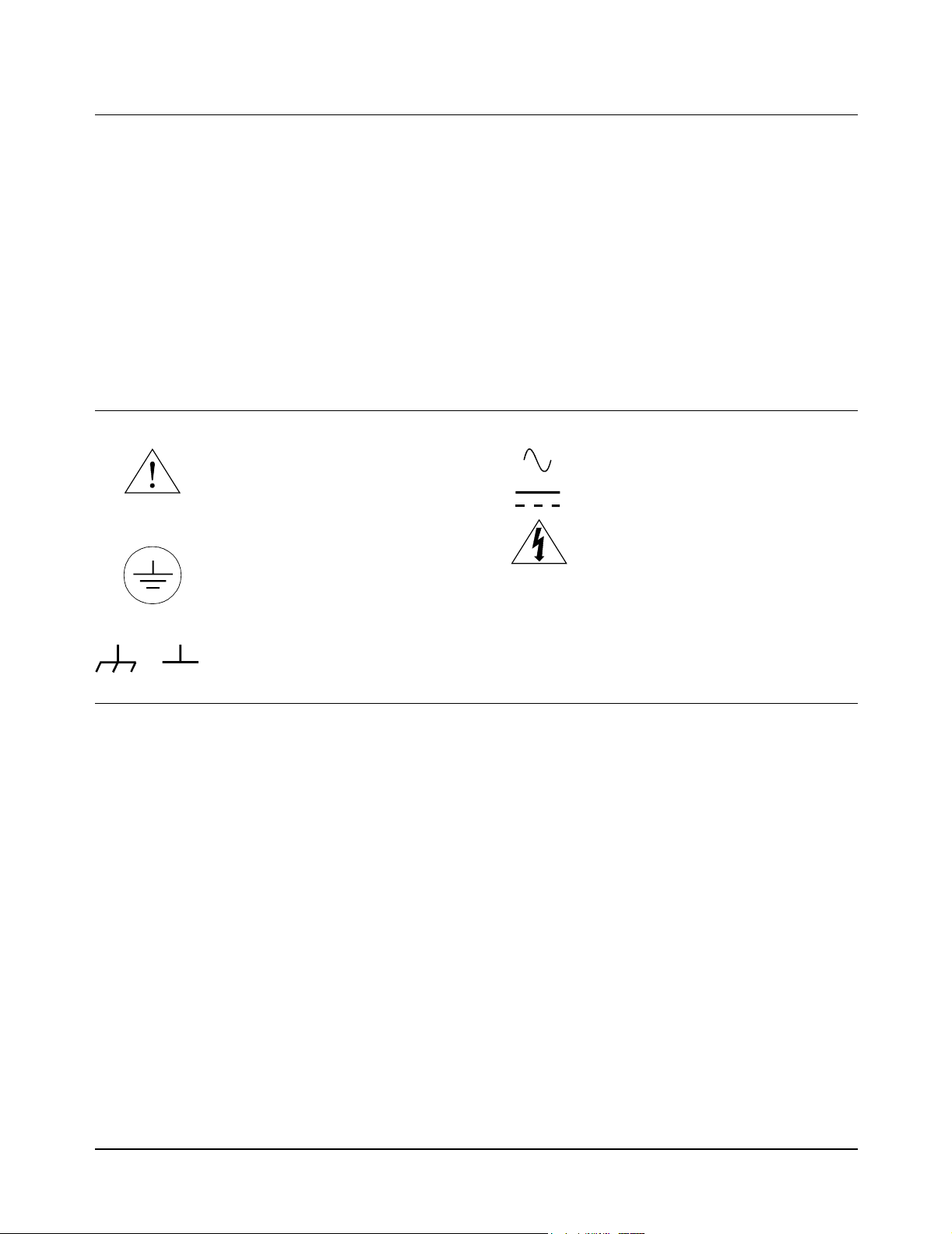
Safety Symbols
Instruction manual symbol affixed to
Instruction manual symbol affixed to
product. Indicates that the user must refer to
product. Indicates that the user must refer to
the manual for specific WARNING or
the manual for specific WARNING or
CAUTION information to avoid personal
CAUTION information to avoid personal
injury or damage to the product.
injury or damage to the product.
Indicates the field wiring terminal that must
be connected to earth ground before
operating the equipment — protects against
electrical shock in case of fault.
WARNING
Alternating current (AC)
Direct current (DC).
Warning. Risk of electrical shock.
Calls attention to a procedure, practice, or
condition that could cause bodily injury or
death.
or
Frame or chassis ground terminal—typically
connects to the equipment's metal frame.
CAUTION
Calls attention to a procedure, practice, or
condition that could possibly cause damage to
equipment or permanent loss of data.
WARNINGS
The following general safety precautions must be observed during all phases of operation, service, and repair of this product. Failure to
comply with these precautions or with specific warnings elsewhere in this manual violates safety standards of design, manufacture, and
intended use of the product. Agilent Technologies assumes no liability for the customer's failure to comply with these requirements.
Ground the equipment: For Safety Class 1 equipment (equipment having a protective earth terminal), an uninterruptible safety earth
ground must be provided from the mains power source to the product input wiring terminals or supplied power cable.
DO NOT operate the product in an explosive atmosphere or in the presence of flammable gases or fumes.
For continued protection against fire, replace the line fuse(s) only with fuse(s) of the same voltage and current rating and type. DO NOT
use repaired fuses or short-circuited fuse holders.
Keep away from live circuits: Operating personnel must not remove equipment covers or shields. Procedures involving the removal of
covers or shields are for use by service-trained personnel only. Under certain conditions, dangerous voltages may exist even with the
equipment switched off. To avoid dangerous electrical shock, DO NOT perform procedures involving cover or shield removal unless you
are qualified to do so.
DO NOT operate damaged equipment: Whenever it is possible that the safety protection features built into this product have been
impaired, either through physical damage, excessive moisture, or any other reason, REMOVE POWER and do not use the product until
safe operation can be verified by service-trained personnel. If necessary, return the product to Agilent for service and repair to ensure that
safety features are maintained.
DO NOT service or adjust alone: Do not attempt internal service or adjustment unless another person, capable of rendering first aid and
resuscitation, is present.
DO NOT substitute parts or modify equipment: Because of the danger of introducing additional hazards, do not install substitute parts
or perform any unauthorized modification to the product. Return the product to Agilent for service and repair to ensure that safety features
are maintained.
10
Page 11

DECLARATION OF CONFORMITY According to ISO/IEC Guide 22 and CEN/CENELEC EN 45014
Manufacturer’s Name: Agilent Technologies, Incorporated
Manufacturer’s Address:
815 - 14
th
ST. S.W.
Loveland, CO 80537
USA
Declares, that the product
Product Name: 2-Channel and 4-Channel Digitizers
Model Number: E1563A/E1564A
Product Options: This declaration covers all options of the above product(s).
Conforms with the following European Directives:
The product herewith complies with the requirements of the Low Voltage Directive 73/23/EEC and the EMC Directive 89/336/EEC
(including 93/68/EEC) and carries the CE Marking accordingly
Conforms with the following product standards:
EMC Standard
IEC 61326-1:1997+A1:1998 / EN 61326-1:1997+A1:1998
CISPR 11:1990 / EN 55011:1991
IEC 61000-4-2:1995+A1:1998 / EN 61000-4-2:1995
IEC 61000-4-3:1995 / EN 61000-4-3:1995
IEC 61000-4-4:1995 / EN 61000-4-4:1995
IEC 61000-4-5:1995 / EN 61000-4-5:1995
IEC 61000-4-6:1996 / EN 61000-4-6:1996
IEC 61000-4-11:1994 / EN 61000-4-11:1994
CISPR 22:1997 / EN 55022:1998
CISPR 24
Canada: ICES-001:1998
Australia/New Zealand: AS/NZS 2064.1
The product was tested in a typical configuration with Agilent Technologies test systems.
Safety
IEC 61010-1:1990+A1:1992+A2:1995 / EN 61010-1:1993+A2:1995
Canada: CSA C22.2 No. 1010.1:1992
UL 3111-1: 1994
IEC 60950: 1991+A1+A2+A3+A4 / EN 60950: 1992+A1+A2+A3+A4+A11
20 March 2001
Date
Limit
Group 1 Class A
4kV CD, 8kV AD
3 V/m, 80-1000 MHz
0.5kV signal lines, 1kV power lines
0.5 kV line-line, 1 kV line-ground
3V, 0.15-80 MHz I cycle, 100%
Dips: 30% 10ms; 60% 100ms
Interrupt > 95%@5000ms
Class A
Ray Corson
Product Regulation Program Manager
Authorized EU-representative: Agilent Technologies Deutschland GmbH, Herrenberger Stra>e 130, D 71034 Böblingen, Germany
For further information, please contact your local Agilent Technologies sales office, agent or distributor.
Revision: B.02 Issue Date: 20 March 2001 Document E9850A.DOC
.
11
Page 12

Notes:
12
Page 13

Configuring the Digitizer Modules
Using This Chapter
This chapter provides guidelines to configure the E1563A and E1564A
modules and to verify successful installation. Chapter contents are:
• Digitizers Description . . . . . . . . . . . . . . . . . . . . . . . . . . . . . . . .13
• Warnings and Cautions . . . . . . . . . . . . . . . . . . . . . . . . . . . . . .17
• Configuring the Digitizers . . . . . . . . . . . . . . . . . . . . . . . . . . . . .19
• User Cabling Connections . . . . . . . . . . . . . . . . . . . . . . . . . . . .23
• Initial Operation . . . . . . . . . . . . . . . . . . . . . . . . . . . . . . . . . . . .30
Digitizers Description
The E1563A (2-channel) and E1564A (4-channel) Digitizers are 800
kSample/second (14-bit resolution) digitizers capable of handling both
continuous and transient voltages up to 256V. You cannot upgrade an
E1563A 2-Channel Digitizer to an E1564A 4-Channel Digitizer.
Chapter 1
General Information Both the E1563A and E1564A digitizers are register-based instruments that
can be programmed at the register level (see Appendix C) or at a higher
level using SCPI or VXIplug&play drivers.
The digitizers are ideal for measurements in electomechanical design
characterization, particularily in environments with high levels of electrical
noise and for characterizing electronic and mechanical transient waveforms.
The E1563A 2-Channel Digitizer has a fixed 25 kHz input filter per channel
that can be enabled. The E1564A 4-Channel Digitizer has four selectable
input filters per channel (1.5 kHz, 6 kHz, 25 kHz and 100 kHz) that can be
enabled.
The E1564A 4-Channel Digitizer has a calibration bus output (High, Low and
Guard) and a programmable short. The E1563A 2-Channel Digitizer does
not have a calibration bus output. However, a programmable short is
provided for each channel. An external calibration source must be provided
for calibration.
Both digitizers use PC SIMM memory. Memory sizes that are supported are
4, 8, 16, 32, 64 and 128 Mbytes. The large memory can easily capture
transients or act as FIFO to allow continuous digitizing while unloading data
with block mode transfers.
Configuring the Digitizer Modules 13Chapter 1
Page 14

All channels sample simultaneously. The sample can be from an internal
clock derived from the internal time base or it can come from an external
source. Triggering can be set up for several sources with programmable pre
and post trigger reading counts. External time base, trigger and sample
inputs are provided on the front panel “D” subminiature connector.
Continuous voltages in a test setup where the user has access to module
connectors and test signal cable ends are restricted to 60 Vdc, 30 Vac rms,
or 42.4 Vac peak of a continuous, complex waveform. Continuous voltages
in test setups where the module connectors and the test signal cables
connected to them are made non-accessible are 256 Vdc, 240 Vdc floating,
or 256 Vac peak.
Transient voltages are permitted providing the maximum amount of charge
transferred into a human body that contacts the voltage under normal
conditions, does not exceed 45
(opens channel input relay) follow.
Range Voltage Input Condition Vmax
62 mV to 4V High or Low to Guard >20V
16V to 256V Low to Guard >40V
mCoulombs (45 mA-s). Overload voltages
Front Panel
Features
Figure 1-1 shows the front panel features for the E1563A 2-Channel
Digitizer. Figure 1-2 shows the front panel features for the E1564A
4-Channel Digitizer.
14 Configuring the Digitizer Modules Chapter 1
Page 15
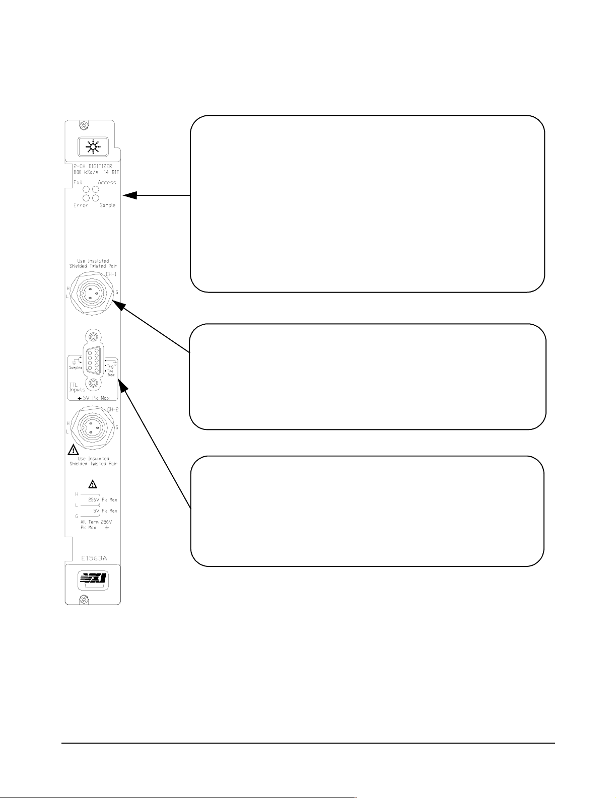
Front Panel Indicators
Failed LED: Illuminates momentarily during digitizer power-on.
Access LED: Illuminates when the backplane is communicating with the
digitizer.
Error LED: Illuminates only when an error is present in the digitizer’s driver
error queue. The error can result from improperly executing a command
or the digitizer being unable to pass self-test or calibration.
Sample LED: Illuminates while the digitizer samples the input for a
measurement. Typically blinks for slow sample rates and is on
steady-state for high sample rates.
User Input Terminals
The E1563A Digitizer front panel contains two female connectors for user
inputs. Mating male connectors are supplied with the module. However,
the user must provide the input cable and connect the male connector to
the cable. See "User Cabling Considerations" for recommended
user-supplied cables.
plug&play
External Trigger Input
The front panel contains a 9-pin D-subminiature connector for external
(TTL) trigger inputs. The user must provide an appropriate input cable to
the external trigger input. The E1563A 2-Channel Digitizer does not have
a calibration bus output. However, a programmable short is provided for
each channel. An external calibration source must be provided for
calibration.
Figure 1-1. E1563A 2-Channel Digitizer Front Panel
Configuring the Digitizer Modules 15Chapter 1
Page 16
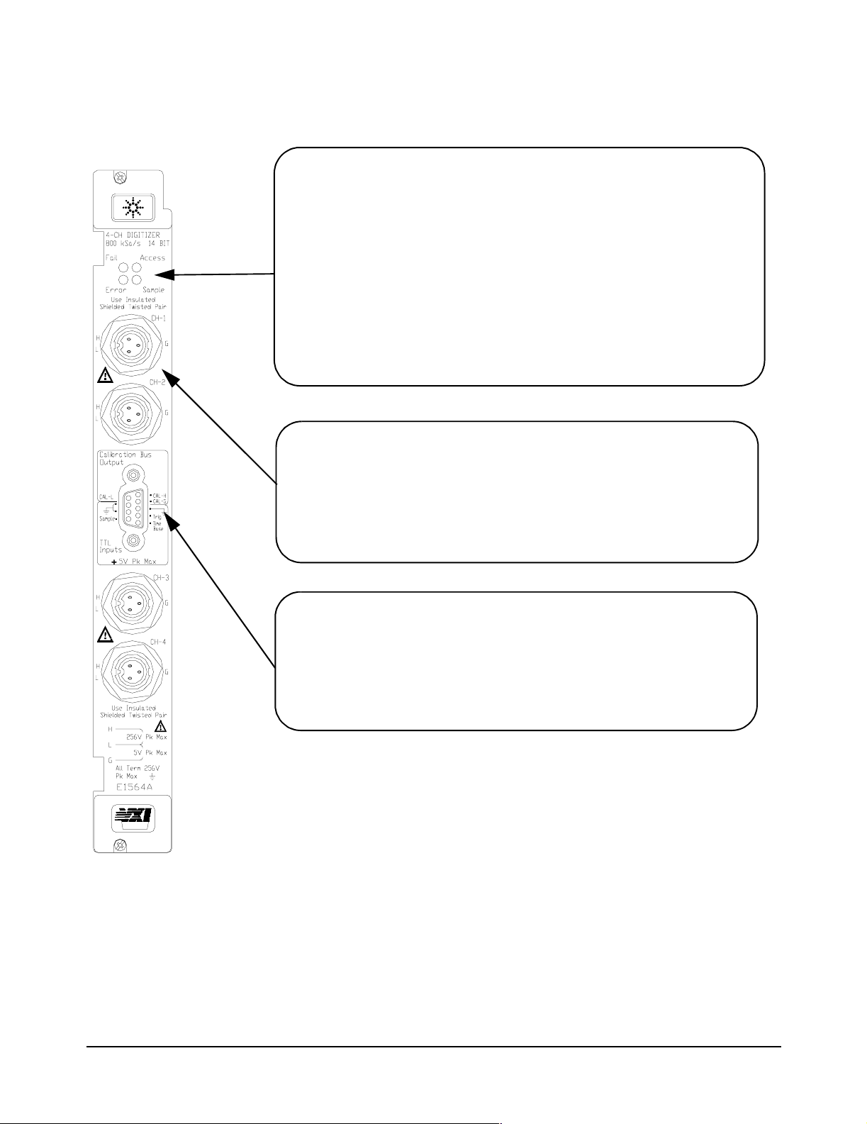
Front Panel Indicators
Failed LED
Access LED: Illuminates when the backplane is communicating with the
: Illuminates momentarily during digitizer power-on.
digitizer.
Error LED: Illuminates only when an error is present in the digitizer’s driver
error queue. The error can result from improperly executing a command
or the digitizer being unable to pass self-test or calibration.
Sample LED: Illuminates while the digitizer samples the input for a
measurement. Typically blinks for slow sample rates and is on
steady-state for high sample rates.
User Input Terminals
The E1564A Digitizer front panel contains four female connectors for user
inputs. Mating male connectors are supplied with the module. However,
the user must provide the input cable and connect the male connector to
the cable. See "User Cabling Considerations" for connecting
user-supplied cables.
plug&play
External Trigger Input/Calibration Bus Output
The front panel contains a 9-pin D-subminiature connector for external
(TTL) trigger inputs and for calibration bus outputs. The E1564A
4-Channel Digitizer has a calibration bus output (High, Low and Guard)
and a programmable short. The user must provide the the appropriate
cable to the external trigger input/calibration bus output.
Figure 1-2. E1564A 2-Channel Digitizer Front Panel
16 Configuring the Digitizer Modules Chapter 1
Page 17

Warnings and Cautions
WARNING DANGEROUS VOLTAGES. The E1563A and E1564A Digitizers are
capable of measuring voltages up to 256V maximum. Voltage levels
above the levels specified for accessible connectors or cable ends
could cause bodily injury or death to an operator. Special precautions
must be adhered to (discussed below) when applying voltages in
excess of 60 Vdc, 30 Vac rms or 42.4 Vac peak for a continuous,
complex waveform.
WARNING MODULE CONNECTORS MUST NOT BE OPERATOR-ACCESSABLE.
Module connectors and test signal cables connected to them must be
made NON-accessible to an operator who has not been told to access
them. It is a supervisor’s responsibility to advise an operator that
dangerous voltages exist when the operator is instructed to access
connectors and cables carrying these voltages.
Making cables and connectors that carry hazardous voltages
inaccessible is a protective measure keeping an operator from
inadvertent or unknowing contact with these harmful voltages.
Cables and connectors are considered inaccessible if a tool
(e.g., screwdriver, wrench, socket, etc.) or a key (equipment in a
locked cabinet) is required to gain access to them. Additionally,
the operator cannot have access to a conductive surface connected
to any cable conductor (High, Low or Guard).
WARNING ADEQUATE INSULATION IS REQUIRED. Assure the equipment under
test has adequate insulation between the cable connections and any
operator-accessible parts (doors, covers, panels, shields, cases,
cabinets, etc.).
Verify there are multiple and sufficient protective means (rated for the
voltages you are applying) to assure the operator will NOT come into
contact with any energized conductor even if one of the protective
means fails to work as intended.
For example, the inner side of a case, cabinet, door, cover or panel
can be covered with an insulating material as well as routing the
test cables to the module’s front panel connectors through
non-conductive, flexible conduit such as that used in electrical
power distribution.
WARNING TIGHTEN MOUNTING SCREWS. Tighten the faceplate mounting
screws after installing the module in the mainframe to prevent
electric shock in case of equipment or field wiring failure.
Configuring the Digitizer Modules 17Chapter 1
Page 18

CAUTION OVERVOLTAGE PROTECTION. To prevent equipment damage,
do not connect this equipment to mains or to any signal directly
derived from mains. Short-term temporary overvoltages must be
limited to 500V or less.
To prevent equipment damage in case of an overvoltage condition,
do not connect this equipment to any voltage source which can
deliver greater than 2A at 500V in the case of a fault. If such a fault
condition is possible, insert a 2A fuse in the input line.
CAUTION CLEANING THE MODULE. Clean the outside surfaces of this
module with a cloth slightly dampened with water. Do not attempt
to clean the interior of this module.
18 Configuring the Digitizer Modules Chapter 1
Page 19
Configuring the Digitizers
This section gives guidelines to configure the digitizers, including:
• Adding RAM to the Module
• Setting the Logical Address Switch
• Setting the Interrupt Line
• Installing the Digitizer in a Mainframe
Adding RAM to the
Module
Selecting a RAM Although most commercially available PC SIMM RAM will work with the
You can increase the size of RAM on your Digitizer module by purchasing
PC SIMM memory and installing it on the module after you remove the
standard 4 Mbyte SIMM shipped with your digitizer. Both FPM (Fast Page
Mode) and EDO (Extended Data Out) are supported.
Digitizer, there are some that are physically too large and will make contact
with the top shield when installed. A standard 72 SIMM specifies the length
(L) or keying but does not specify the depth (D). Certain depths are too large
and not compatible.
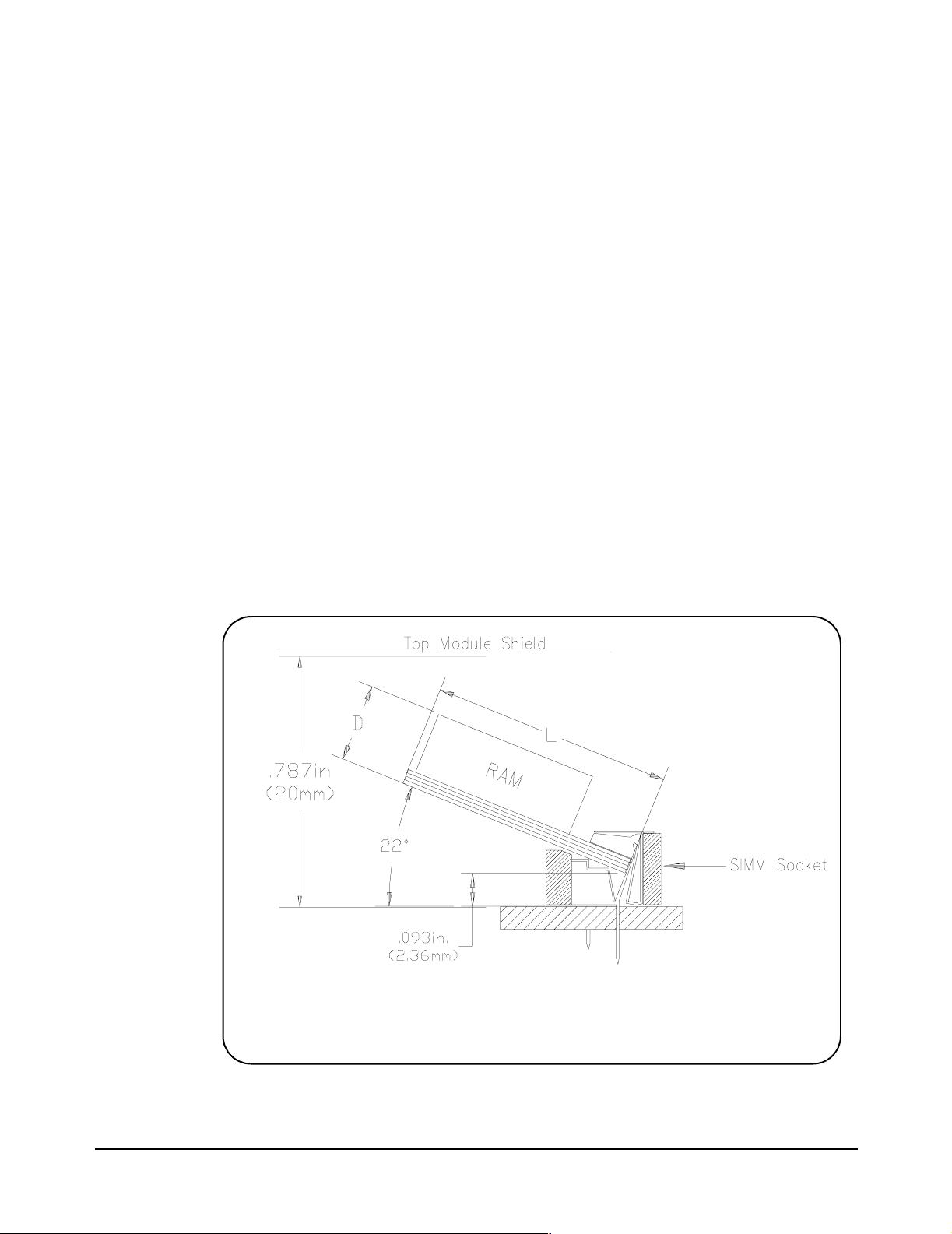
The E1563/E1564 has about 17.6 mm of space from the bottom of the
SIMM RAM inserted in the socket to the top module shield (see Figure 1-3).
You must verify that the SIMM RAM you purchase for replacement on the
module has a depth (D) that will clear the top module shield. You can use
the 4 Mbyte SIMM RAM you remove as a guide, as well as the dimensions
in Figure 1-3, when purchasing your upgrade RAM .
L = 1.25in (31.77mm) max for D = 0.18, where D is from PC board lower side
where it rests on the bracket. D does not include the height of chips mounted
on the lower side of the board.
Figure 1-3. Adding RAM to the Module
Configuring the Digitizer Modules 19Chapter 1
Page 20

RAM Installation
Procedure
NOTE It is important that you retain the 4 Mbyte SIMM you remove from the
1 Disconnect any field wiring from the module and remove power from
the mainframe before proceeding.
2 Remove the module from the mainframe and remove the top shield
from the module.
3 Remove the 4 Mbyte SIMM from the PC board by first spreading the
tabs at the ends of the SIMM connector. Store this SIMM in an
anti-static bag and save this part.
Digitizer. If you return your Digitizer to Agilent for repair or exchange, you
must return it in the same configuration as it was shipped to you. You must
remove the large memory SIMM and replace it with the standard 4 Mbyte
SIMM shipped with the product.
4 Add your replacement SIMM to the module’s RAM socket.
5 Reinstall the module’s top shield.
6 Note the new memory configuration by checking the appropriate box
on the module’s top shield.
7 Set the “CALIBRATION CONSTANTS” switch and the “FLASH”
switch to the “Write Enable” position.
8 Install the module in the mainframe and apply power.
9 Set the new RAM memory size by sending
DIAGnostic:MEMory:SIZE <size>.
10 Query the memory size to verify the setting by sending
DIAGnostic:MEMory:SIZE?
11 Remove mainframe power, remove the module and set the
“CALIBRATION CONSTANTS” and “FLASH” switches back to the
“Read Only” position.
12 Reinstall the module in the mainframe.
WARNING TIGHTEN THE FACEPLATE SCREWS. Tighten the faceplate mounting
screws to prevent electric shock in case of equipment or field wiring
failure.
20 Configuring the Digitizer Modules Chapter 1
Page 21
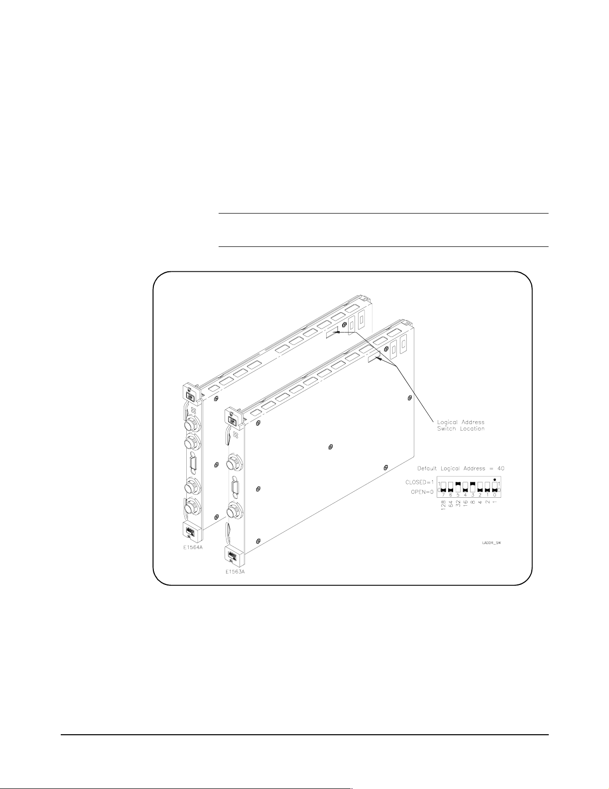
Setting the Logical
Address Switch
NOTE When using an E1406A as the VXIbus resource manager with SCPI
The E1563A and E1564A Digitizers are shipped from the factory with logical
address 40. Valid logical address are from 1 to 254 for static configuration
(the address you set on the switch) and address 255 for dynamic
configuration. The E1563A and E1564A do not support dynamic
configuration of the address.
If you install more than one digitizer, each module must have a different
logical address. If you use a VXIbus command module, the logical address
must be a multiple of eight (e.g., 32, 40, 48, 56, etc.). Each instrument must
have a unique secondary address which is the logical address divided by
eight. See Figure 1-4 for guidelines to set the Logical Address Switch.
commands, the digitizer’s address switch value must be a multiple of 8.
Setting the Interrupt
Line
Figure 1-4. Setting the Logical Address Switch
The E1563A and E1564A Digitizers are VXIbus interrupters. You can
specify which interrupt line (1 through 7) the interrupt is transmitted. The
interrupt line is specified using DIAGnostic:INTerrupt:LINE. You can query
the active interrupt line using DIAGnostic:INTerrupt:LINE?. The default is no
interrupt line enabled at power-up. You specify “0” if you do not want an
interrupt. Resetting the module does change the interrupt line setting and
you must reset your interrupt setting.
Configuring the Digitizer Modules 21Chapter 1
Page 22
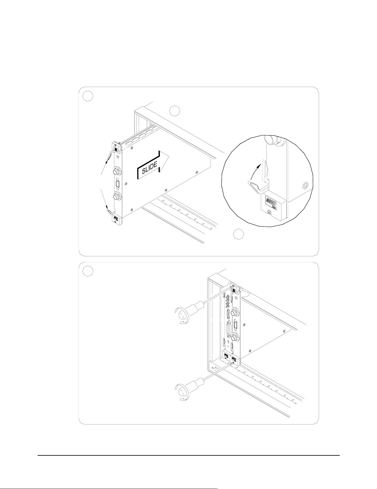
Installing the
Digitizer in a
Mainframe
Set the extraction levers out.1
Extraction
Levers
The E1563A or E1564A Digitizer can be installed in any slot (except slot 0)
in a C-size VXIbus mainframe. See Figure 1-5 for the procedure to install the
Digitizer in a mainframe.
Slide the E1563/E1564 into any slot
2
(except slot 0) until the backplane
connectors touch.
4
Tighten the top and bottom screws
to secure the digitizer module
to the mainframe.
NOTE: The extraction levers will not
seat the backplane connectors on older
VXIbus mainframes. You must manually
seat the connectors by pushing in the
module until the module's front panel is
flush with the front of the mainframe. The
extraction levers may be used to guide or
remove the digitizer.
To remove the digitizer from the mainframe,
reverse the procedure.
Seat the digitizer into
3
the mainframe by pushing
in the extraction levers.
Figure 1-5. Installing the Digitizer in a Mainframe
22 Configuring the Digitizer Modules Chapter 1
Page 23
User Cabling Considerations
This section gives guidelines to select and configure user-supplied cables
for connection to the Input Terminals and to the External Trigger
Input/Calibration Bus Output Terminals.
Input Terminal Port
Connector Cables
E1563A Digitizer. The E1563A Digitizer front panel includes two Switchcraft®
EN3™ Mini Weathertight Connectors (female) (CH-1 and CH-2). See Figure
1-1. Mating Switchcraft® Cord Connectors (male) are supplied with the
module. However, the user must provide the cable and assemble the
connector to the cable end. Recommended shielded, twisted-pair cable in
the following table have an outside dimension compatible with the cord
connector.
Wire gauge Belden® cable P/N Alpha® cable P/N
20 AWG (7x28) 8762 none
22 AWG (7x30) 9462 5481C
24 AWG (7x32) 8641 5491C
E1564A Digitizer. The E1564A Digitizer front panel contains four
Switchcraft® EN3™ Mini Weathertight Connectors (female) (CH-1 through
CH-4). See Figure 1-2. Mating Switchcraft® Cord Connectors (male) are
supplied with the module. However, the user must provide the cable and
assemble the connector to the cable end. Recommended shielded,
twisted-pair cable in the following table have an outside dimension
compatible with the cord connector.
Wire gauge Belden® cable P/N Alpha® cable P/N
20 AWG (7x28) 8762 none
22 AWG (7x30) 9462 5481C
24 AWG (7x32) 8641 5491C
Configuring the Digitizer Modules 23Chapter 1
Page 24
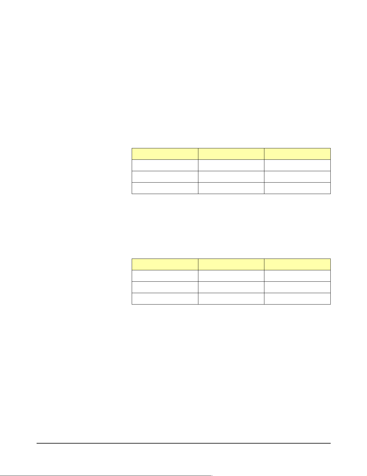
Trigger Input Port
Cables
SAMPle:SOURce EXT
The user must supply a standard cable to the External Trigger Input port
(E1563A) or to the External Trigger Input/Calibration Bus Output port
(E1564A).
E1563A Digitizer. The E1563A front panel contains a 9-pin D-subminiature
connector with the pin-outs and associated SCPI commands shown in
Figure 1-6 (do not make any connections to the top two pins).
TRIGger:SOURce EXT
ROSCillator:SOURce EXT
Figure 1-6. E1563A External Trigger Input Port
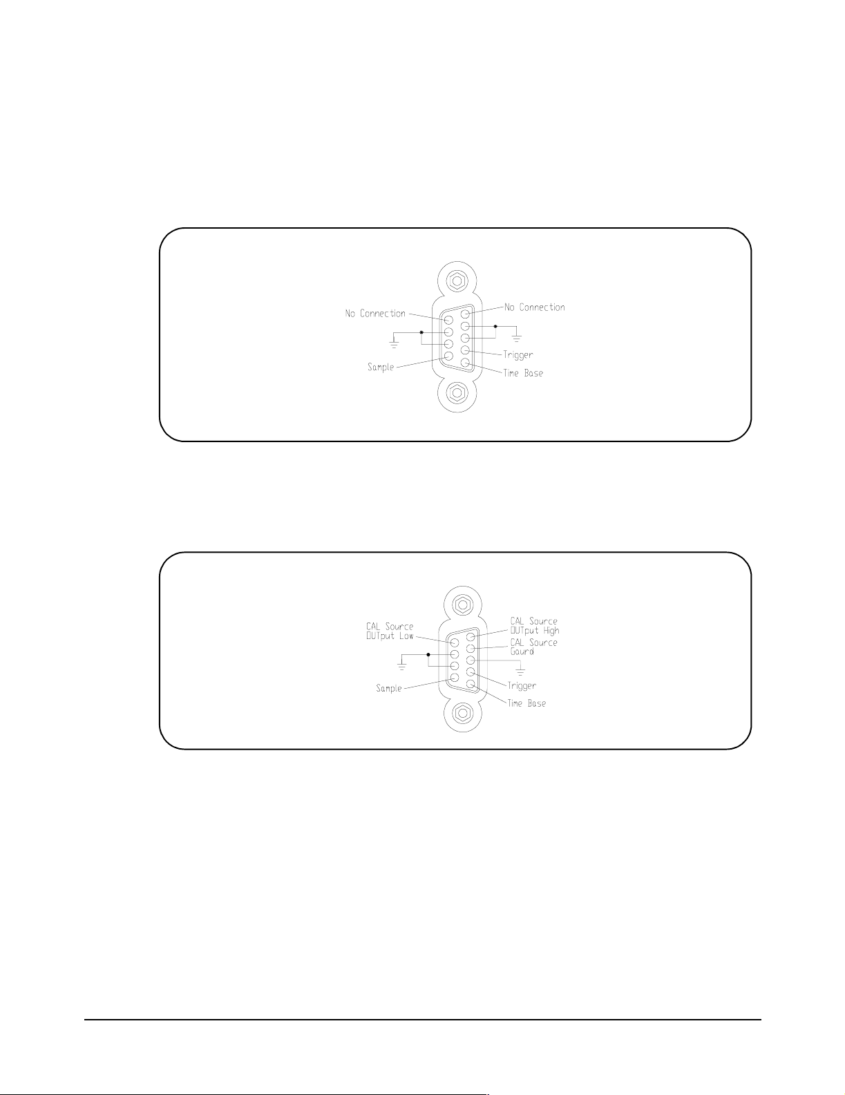
E1564A Digitizer. The E1564A front panel contains a 9-pin D-subminiature
connector with the pin-outs and associated SCPI commands shown in
Figure 1-7.
CAL:SOURce INT
SAMPle:SOURce EXT
Figure 1-7. E1564A External Trigger Input/Calibration Bus Output Port
3-Wire and 2-Wire
Input Cabling
Considerations
CAL:SOURce INT
TRIGger:SOURce EXT
ROSCillator:SOURce EXT
The E1563A and E1564A Digitizers provide a three-terminal input system
(High, Low and Guard) in which an unavoidable and undesirable current is
injected from chassis ground to the Guard terminal. Dependent on whether
you measure on a low-voltage range or a high-voltage range, the way you
connect the Guard terminal may or may not introduce a measurement error
due to this current. This section describes some considerations you can
take to use the Guard terminal properly to minimize measurement error.
24 Configuring the Digitizer Modules Chapter 1
Page 25
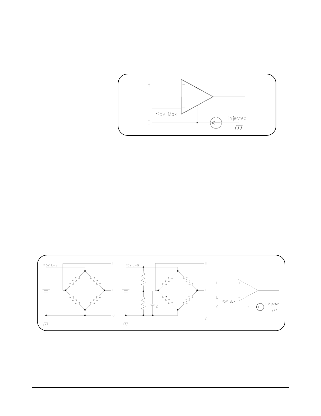
Digitizer Input Model Figure 1-8 shows the input model for the digitizer. Maximum voltage
between Low and Guard is 5V. Exceeding this limitation will not damage
your digitizer but will generate invalid data for any measurement taken.
In general, 3-Wire cabling is recommended, but 2-Wire cabling is supported
for some switching applications.
Figure 1-8. Digitizer Input Model
Three-Wire Connections This section shows two examples of connecting the input using a three-wire
connection. Both example connections can be made using shielded,
twisted-pair connectors.
For the first example, Figure 1-9 shows one way to make connections for a
bridge measurement where the L-to-G voltage is £ 5V and the L-to-G
voltage exceeds 5V. A “Wagner ground” is used to satisfy the L-to-G
restriction of £ 5V and to make a Guard connection point that minimizes
measurement error due to the digitizer’s injected current. A capacitor is
added to the Wagner ground to provide a signal path to ground to minimize
common mode voltages.
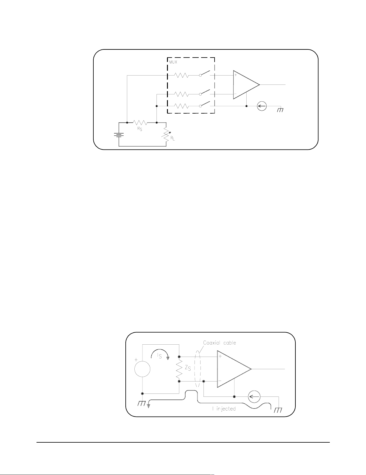
For the second example, Figure 1-10 shows one way to measure the voltage
across a small current sensing resistor where the input to the digitizer is
switched through a multiplexer switch module.
Figure 1-9. Example: Three-Wire Connections (Bridge)
Configuring the Digitizer Modules 25Chapter 1
Page 26
.
Figure 1-10. Example: Three-Wire Connections (Voltage Measurements)
Two-Wire Connections When Low and Guard are connected together at the digitizer’s input on a
low-voltage range (4V and below), the injected current is directed to flow
through the source impedance (in a floating source) and the resultant
voltage drop will introduce a measurement error.
The resultant voltage drop through the source impedance can be a
significant error on low-voltage ranges where the voltage of interest is small.
It is not as significant an error on high-voltage ranges because the error
introduced is not a significant part of a larger voltage and the percent of error
is less significant.
Measurement error can increase significantly when you connect Low to
Guard at the digitizer’s input AND use switches to switch input signals to the
digitizer. Some switches have input protection resistors (usually 100W) in
series with the switch. The digitizer’s injected current now generates a
voltage drop across this resistor in addition to the voltage drop generated
across the source impedance. Even with a grounded source, an error
voltage is generated across the switches current limiting resistor.
Two examples of two-wire connections follow. For the first example, Figure
1-11 shows a typical connection using coaxial cable. For the second
example, Figure 1-12 shows connections for a differential source.
Figure 1-11. Example: Two-Wire Connections (Coaxial Cable)
26 Configuring the Digitizer Modules Chapter 1
Page 27
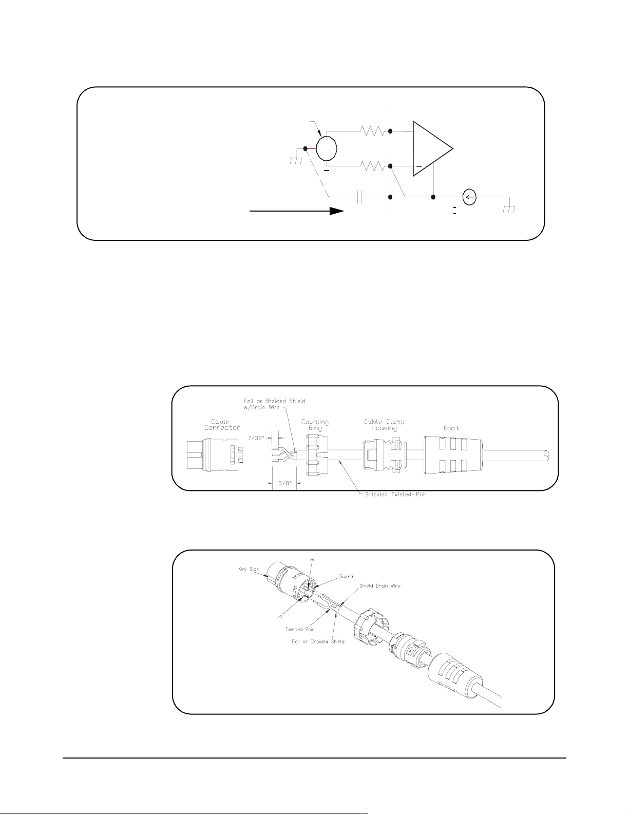
Add 100 pF capacitor if low-level
25 kHz noise from injected current
is present.
Figure 1-12. Example: Two-Wire Connections (Differential Source)
Differential
Source
100 pF
50
+
50
25 KHz From
Switching Supply
I Injected
+
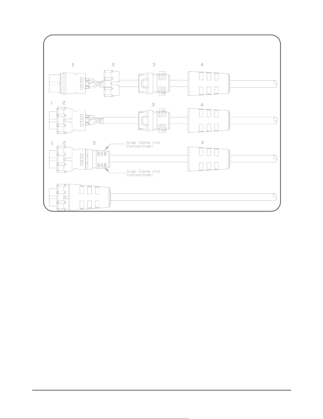
Cable Connector
Assembly
Step 1 Strip cable as shown and feed the end of the cable through the boot, cable
Step 2 Orient the HI, LO and Guard conductors with the corresponding pins.
This section gives guidelines to connect user-supplied cables to the cable
connector supplied with the E1563A and E1564A Digitizers. See "Terminal
Port Connector Cables" for recommended user-supplied cables.
clamp housing, and coupling ring in the order and position shown. The
coupling ring can also be inserted onto the cable connector from the front.
Configuring the Digitizer Modules 27Chapter 1
Page 28
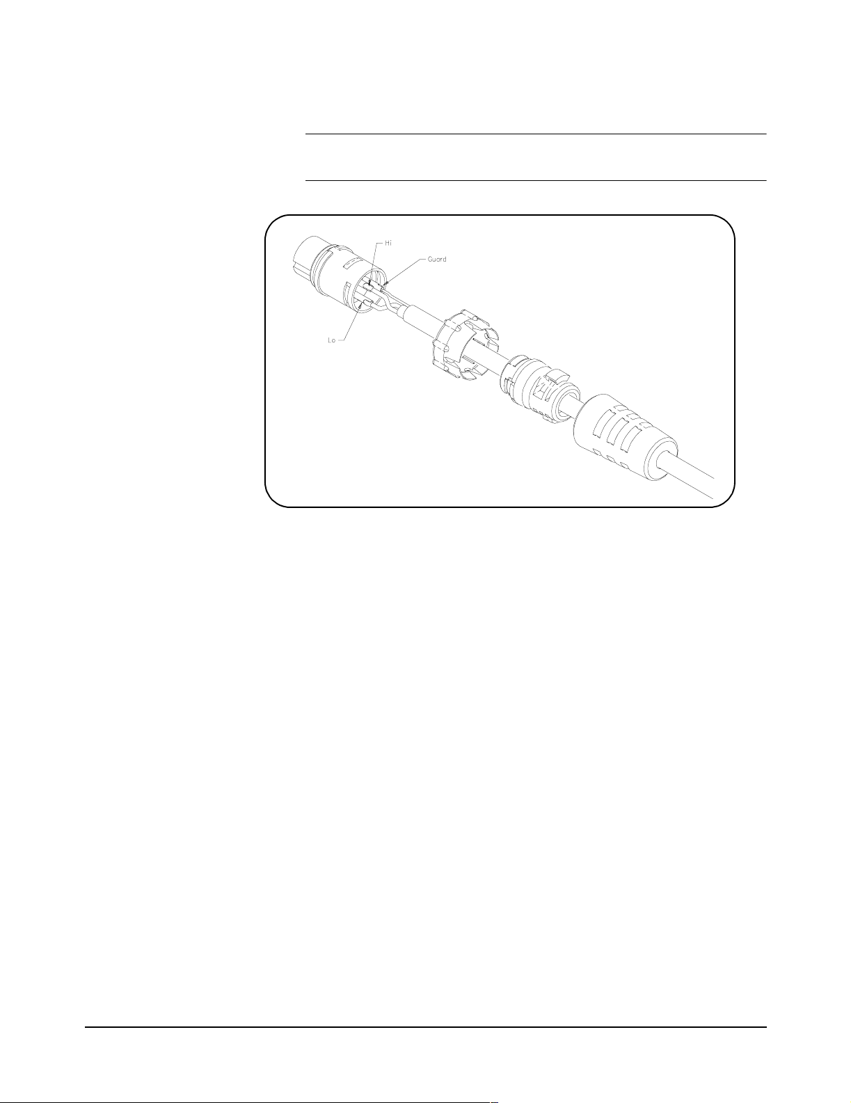
Step 3 Solder conductors to pins.
CAUTION AVOID EXCESSIVE HEAT. Excessive heat on the connector
terminals can cause damage to the connector.
Step 4 Assemble the connector.
A. Align coupling ring’s tabs with cable connector’s side notches and push
the coupling ring onto the cable connector.
B. Push the cable clamp housing forward until it locks into the connector
body and snap the two clamps into their compartments to secure the cable.
C. Push the boot all the way forward to seat tightly onto the cable clamp
housing.
28 Configuring the Digitizer Modules Chapter 1
Page 29
Cable Coupling Cable Clamp Boot
Connector Ring Housing
Step 5 Mate the cable connector to the User Input Terminal Port.
1 Hold the cable connector by the rubber boot and align the notched
key slot with the key on the left side of the instrument’s front panel
connector. Insert the cable connector just enough to encounter
insertion resistance and stay in place.
2 Grasp the coupling ring and slowly rotate it clockwise, while you
gently push the connector toward the panel mount, until the notches
on the coupling ring drop into the front panel connector detents.
3 Continue rotating until you feel the coupling ring ride over the locking
“bump” which secures the connector to the instrument’s front panel
connector.
Configuring the Digitizer Modules 29Chapter 1
Page 30

Initial Operation
NOTE This discussion applies only to Standard Commands for Programmable
NOTE The E1563A or E1564A Digitizer may have experienced temperature
To program the E1563A or E1564A Digitizer using Standard Commands for
Programmable Instruments (SCPI), you must select the interface address
and SCPI commands to be used. Information about using SCPI commands
is presented in Chapter 3.
Programming a digitizer using SCPI requires that you select the controller
language (C, C++, BASIC, Visual Basic, etc.), interface address and SCPI
commands to be used.
Instruments (SCPI) programming. The example program listed is written
using Virtual Instrument Software Architecture (VISA) function calls.
VISA allows you to execute on VXIplug&play system frameworks that
have the VISA I/O layer installed (visa.h “include” file).
extremes during shipment that can affect its calibration. It is recommened
you perform a zero offset calibration upon receipt using CAL:ZERO
<channel>:ALL? for each channel to meet the accuracy specifications
in Appendix A. See Appendix E for the zero adjustment procedure.
Example: Initial Operation
This C program verifies communication between the controller, mainframe
and digitizer. It resets the module (*RST), queries the identity of the module
(*IDN?) and queries the module for system errors.
#include <stdio.h>
#include <visa.h>
/*** FUNCTION PROTOTYPE ***/
void err_handler (ViSession vi, ViStatus x);
void main(void)
{
char buf[512] = {0};
#if defined(_BORLANDC_) && !defined(_WIN32_)
_InitEasyWin();
#endif
ViStatus err;
ViSession defaultRM;
ViSession digitizer;
/* Open resource manager and digitizer sessions */
viOpenDefaultRM (&defaultRM);
viOpen(defaultRM, “
GPIB-VXI0::9::40”,VI_NULL,VI_NULL, &digitizer);
30 Configuring the Digitizer Modules Chapter 1
Page 31

/* Set the timeout value to 10 seconds. */
viSetAttribute (digitizer, VI_ATTR_TMO_VALUE, 10000);
/* Reset the module. */
err = viPrintf(digitizer, “*RST\n”);
if (err<VI_SUCCESS) err_handler (digitizer, err);
/* Query for the module’s identification string. */
err = viPrintf(digitizer, “*IDN?\n”);
if (err<VI_SUCCESS) err_handler (digitizer, err);
err = viScanf(digitizer, “%t”, buf);
if (err<VI_SUCCESS) err_handler (digitizer, err);
printf (“Module ID = %s\n\n”, buf);
/* Check the module for system errors. */
err = viPrintf(digitizer, “*SYST:ERR?\n”);
if (err<VI_SUCCESS) err_handler (digitizer, err);
err = viScanf(digitizer, “%t”, buf);
if (err<VI_SUCCESS) err_handler (digitizer, err);
printf (“System error response = %s\n\n”, buf);
viClose (digitizer); /* close the digitizer session */
} /* end of main */
/*** Error handling function ***/
void err_handler (ViSession digitizer, ViStatus err)
{
char buf[1024] = {0};
viStatusDesc (digitizer, err, buf); /* retrieve error description */
printf (“ERROR = %s\n”, buf);
return;
}
Configuring the Digitizer Modules 31Chapter 1
Page 32

Notes:
32 Configuring the Digitizer Modules Chapter 1
Page 33

Using this Chapter
This chapter gives guidelines to use the E1563A and E1564A Digitizers,
including:
Digitizers Operation
This section shows block diagram operation for the E1563A and E1564A
Digitizers, including digitizer block diagrams, power-on/reset states, and
input overload conditions.
Chapter 2
Using the Digitizers
• Digitizers Operation . . . . . . . . . . . . . . . . . . . . . . . . . . . . . . . . .33
• Triggering the Digitizers . . . . . . . . . . . . . . . . . . . . . . . . . . . . . .37
• Digitizers Application Examples . . . . . . . . . . . . . . . . . . . . . . . .42
Digitizer Block
Diagram
Figure 2-1 shows a block diagram of the E1564A 4-Channel Digitizer.
The E1563A 2-Channel Digitizer has the same internal structure without
channels 3 and 4. TRIG:LEVel <channel> signals drive the internal trigger
inputs, LEVel1 drives INT1, LEVel2 drives INT2, etc.
Figure 2-1. Digitizer Block Diagram
Using the Digitizers 33Chapter 2
Page 34

Channel Block
Diagram
Figure 2-2 is a block diagram of an individual channel and the
interconnections between channels. The sample signal goes to all channels.
The commands beneath the diagram show the SCPI commands used to
program each section of a channel. In this case, all the commands are
written for channel 4. See Chapter 3 for a full description of the commands
illustrated here.
RANGE SELECTION:
INPut4:STATe ON | 1 | OFF | 0
VOLTage4:DC:RANGe <range>
FILTER SETTING:
INPut4:FILTer:LPASs:FREQ <freq>
INPut4:FILTer:LPASs:STATe ON | 1 | OFF | 0
Figure 2-2. Digitizer Channel Block Diagram
QUERY LAST READING (current value):
SENSe:DATA:CVTable? (@4)
LIMIT and LEVEL COMPARISON:
CALCulate4:LIMit:LOWer:DATA <value>
CALCulate4:LIMit:LOWer:STATe ON | 1 | OFF | 0
or
CALCulate4:LIMit:UPPer:DATA <value>
CALCulate4:LIMit:UPPer:STATe ON | 1 | OFF | 0
or
TRIGger:SOURce INTernal4
TRIGger:LEVel4 <voltage>
TRIGger:SLOPe4 POS | 1 | NEG | 0
34 Using the Digitizers Chapter 2
Page 35

Pre-Trigger/
Post-Trigger Block
Diagram
Figure 2-3 illustrates relationship of pre-trigger readings and post-trigger
readings with the trigger event. See Chapter 3 for a full description of the
commands illustrated here.
Figure 2-3. Pre-Trigger/Post-Trigger Block Diagram
Power-on/Reset
States
Parameter Power-on/Reset State Parameter Power-on/Reset State
DIAG:INTerrupt:LINE interrupt line #1 VOLT4:RANGe 256V (channel 4 range)
FORMat:DATA ASCii VOLT1:RESolution 7.8125 mV (channel 1 res)
INPut1:FILTer:FREQ 0 (no filter on channel 1 ) VOLT2:RESolution 7.8125 mV (channel 2 res)
INPut2:FILTer:FREQ 0 (no filter on channel 2 ) VOLT3:RESolution 7.8125 mV (channel 3 res)
INPut3:FILTer:FREQ 0 (no filter on channel 3 ) VOLT4:RESolution 7.8125 mV (channel 4 res)
INPut4:FILT:FREQ 0 (no filter on channel 4 ) SAMPle:COUNt 1 (one sample)
INPut1:STATe ON (channel 1 input state) SAMPle:PRETrigger:COUNt 0 (no pretrigger samples)
INPut2:STATe ON (channel 2 input state) SAMPle:SLOPe POSitive
INPut3:STATe ON (channel 3 input state) SAMPle:SOURce TIMer (internal time base)
INPut4:STATe ON (channel 4 input state) SAMPle:TIMer 1.3 µsec
Table 2-1 describes all power-on and reset states for the digitizer. The reset
state after executing *RST is the same as the power-on state.
Table 2-1. Power-on and Reset States.
OUTPut:TTLT0-7:SOURce TRIGger (all TTLTrigger
lines)
TRIGger:LEVel1 -256V (channel 1 level)
Using the Digitizers 35Chapter 2
Page 36

Table 2-1. Power-on and Reset States.
Parameter Power-on/Reset State Parameter Power-on/Reset State
OUTPut:TTLT0-7:STATe OFF (all TTLTrigger lines) TRIGger:LEVel2 -256V (channel 2 level)
ROSCillator:SOURce INTernal TRIGger:LEVel3 -256V (channel 3 level)
SWEep:POINts 1 (one sample) TRIGger:LEVel4 -256V (channel 4 level)
SWEep:OFFSet:POINts 0 (no pretrigger samples) TRIGger:SOURce1 IMMediate (source 1
not ch 1)
VOLT1:RANGe 256V (channel 1 range) TRIGger:SOURce2 HOLD (source 2 not ch 2)
VOLT2:RANGe 256V (channel 2 range) TRIGger:SLOPe1 POSitive (slope 1 not ch 1)
VOLT3:RANGe 256V (channel 3 range) TRIGger:SLOPe2 POSitive (slope 2 not ch 2)
Input Overload
Condition
NOTE Relays open at approxiately 260V. If this happens, you must reprogram the
Overload voltages may occur which will open the channel input relay
disconnecting the input signal from the channel. Overload voltage by range
is shown in the following table.
Range Voltage Input Condition Vmax
62 mV to 4V High or Low to Guard >20V
16V to 256V Low to Guard >40V
The overload is reported both when the readings are retrieved and when the
next measurement is initiated. If an overload occurred, an error message is
returned when data is retrieved informing you that the data is questionable
(Overload detected - data questionable)
when you initiate the next measurement
re-connect of input relays).
. An error message is also returned
(Overload detected - attempting
input range to close by executing INP <channel> ON.
36 Using the Digitizers Chapter 2
Page 37

Triggering the Digitizers
This section describes digitizer triggering, including:
• Trigger Sources
• Using Internal Triggering
• Using External Triggering
• Master/Slave Operation
Trigger Sources Triggering digitizer readings across all input channels is accomplished
with one or both of the two trigger sources (TRIGger:SOURce1 and
TRIGger:SOURce2). The trigger event can be different for each source.
For example, SOURce1 can be EXT and SOURce2 can be TTLT0. Use
TRIG:SOURce<n> to set the trigger source event options which can be
OFF | BUS | EXT | HOLD | IMMEDIATE | INTernal1-4 | TTLT0-7.
You must execute TRIG:SOURce<n> two times to set both trigger sources
(TRIG:SOUR1 and TRIG:SOUR2). At power-up and after resetting the
module with *RST, TRIG:SOUR1 defaults to IMM and TRIG:SOUR2
defaults to HOLD. The number of readings set by SAMPle:COUNt are
taken after the trigger event occurs.
NOTE Do not confuse TRIG:SOUR1 as being associated with only channel 1
(as well as TRIG:SOUR2 with only channel 2). Both sources are common
to ALL channels and the “1” and “2” are not channel designators but
“source” designators.
Using Internal
Triggering
Using SCPI or VXIplug&play, you can trigger internally from a voltage
level from any channel. The trigger level is set using TRIG:LEVel<channel>
<voltage> for the channel you want to generate the trigger event. You then
set the trigger source to trigger internally from that channel using
TRIG:SOURce<n>INT<channel>. For example, to trigger from a 11.5V
level on channel 2, send VOLT2:RANG 16; TRIG:LEV2 11.5;
TRIG:SOUR INT2. Figure 2-1 shows the relationship of the trigger level to
the internal trigger source.
Each channel has a level compare circuit that compares the input signal to
the value set by the TRIG:LEVel<channel> command. This level initiates a
trigger when the input signal equals or exceeds the value set by TRIG:LEVel
This means the trigger can occur at a value other than the value set by the
TRIG:LEVel command.
For example, assume a trigger level of 0V on a ramp from -1V to +1V.
The first samples may be negative values close to zero. These values will
not cause a trigger because they do not equal or exceed the trigger level
value yet. The next sample may be a positive value greater than the trigger
level. The trigger compare circuit (see Figure 2-4) detects this level is equal
to or greater than the trigger level value set and a trigger is generated.
It was not, however, generated at the exact trigger level value set by the
TRIG:LEVel command.
Using the Digitizers 37Chapter 2
Page 38

Figure 2-4. Trigger Level Compare Circuit Operation
Using External
Triggering
Master-Slave
Operation
Master-Slave
Synchronization
You can provide an external trigger common to all channels. The external
trigger connection is on the digitizer’s External Trigger Input D-subminiature
connector “Trig” pin. You set this input as the trigger source for all channels
using TRIGger:SOURce<n> EXT. Use TRIGger:SLOPe<n> POSitive |
NEGative to set which signal edge will trigger.
The E1563A and E1564A Digitizers can be configured in a master-slave
configuration. This configuration allows a master module and one or more
slave modules to have their measurements synchronized. Synchronization
occurs when all channels trigger from the same trigger event and all
channels sample from one sample signal.
The sample synchronization signal is always generated by the master.
The TTL trigger event can be generated by either the master module or any
of the slave modules. This allows a slave module (as well as the master
module) to use one of the four internal trigger sources or their external
trigger source to trigger a measurement.
Both the trigger signal and the sample signal are placed on the VXI
backplane TTL trigger (TTLT) lines where the master module and all slave
modules receive the signals simultaneously. TTL trigger lines are used in
pairs between the master and slave(s) where one TTL trigger line carries the
sample signal and the other carries the trigger signal. The next section
describes how these TTL trigger lines are paired.
TRIGger:MODE is used to configure Digitizers for master-slave operation.
The mode can be NORMal, MASTer or SLAVe. The default setting for
trigger mode is TRIGger:MODE NORMal which configures the module
as an individual instrument.
38 Using the Digitizers Chapter 2
Page 39

TRIGger:MODE MASTer<n> configures a module as a master. The eight
TTL trigger lines (TTLT0-TTLT7) on the VXI backplane allow four different
pairings as shown in Table 2-2 (MASTer0 - SLAVe0, MASTer2 - SLAVe2,
MASTer4 - SLAVe4 and MASTer6 - SLAVe6).
NOTE You must select an unused set of TTL trigger lines for the master-slave
coupling when determining which master mode to set. Do not use a TTLT
line already used by SAMPle:SOURce or TRIGger:SOURce.
TRIGger:MODE SLAVe0 configures a module as a slave to a MASTer0
module. MASTer0 and SLAVe0 modules share TTL trigger lines TTLT0
and TTLT1. TTLT0 carries the sample signal and TTLT1 carries the trigger
signal. Table 2-2 shows all pairs of TTL trigger lines for each master-slave
mode.
Table 2-2. Trigger Sources for Master-Slave Modes.
MASTer-SLAVe
Trigger Sources
MASTer MODE SLAVe MODE TRIG:SOUR1 TRIG:SOUR2
MASTer0 SLAVe0 TTLT1 Any source except TTLT0 & TTLT1
MASTer2 SLAVe2 TTLT3 Any source except TTLT2 & TTLT3
MASTer4 SLAVe4 TTLT5 Any source except TTLT4 & TTLT5
MASTer6 SLAVe6 TTLT7 Any source except TTLT6 & TTLT7
Example: Master Module
Configuration
Figure 2-5 illustrates a module configured as a master module. TRIG:MODE
MASTer0 pairs TTLT0 (sample) with TTLT1 (trigger). The MASTer0 module
will function with all SLAVe0 modules.
Figure 2-5. Example: Master Module Configuration
Using the Digitizers 39Chapter 2
Page 40

The trigger source from the master can be set with TRIG:SOURce1,2 IMM
| INT1-4 | EXT | TTLT<n>.
MODE MASTer Sample Signal
MASTer0 TTLT2-7 | INT1-4 | EXT
MASTer2 TTLT0,1,4-7 | INT1-4 | EXT
MASTer4 TTLT0-3,6-7 | INT1-4 | EXT
MASTer6 TTLT0-5 | INT1-4 | EXT
TRIG:MODE MASTer0 drives the TTL lines as if OUTPut:TTLT0:
SOURceSAMPle and OUTPut:TTLT1:SOURce TRIGger had been set.
The master module generates the sample signal from which all modules
(master and slaves) initiate a measurement.
MASTer0 sets the TTLT1 line as if it were TRIG:SOUR1 TTLT1. However,
the query TRIG:SOUR? will not return this setting. This line is dedicated for
synchronization between the two modules in the master-slave mode. You
should not use this line for any other purpose with the OUTPut, SAMPle or
TRIGger commands.
Example: Slave Module
Configuration
Figure 2-6 illustrates a module configured as a slave module. TRIG:MODE
SLAVe0 pairs TTLT0 (sample) with TTLT1 (trigger). A SLAVe0 module will
function with other SLAVe0 modules and with the MASTer0 module.
Figure 2-6. Slave Module Configuration
40 Using the Digitizers Chapter 2
Page 41

The trigger source from the slave can be set with TRIG:SOURce2 IMM |
INT1-4 | EXT | TTLT<n>.
MODE SLAVe Sample Signal
SLAVe0 TTLT0
SLAVe2 TTLT2
SLAVe4 TTLT4
SLAVe6 TTLT6
SLAVe0 sets the TTLT0 line as if it were SAMP:SOUR TTLT0 and sets the
TTLT1 line as if it were TRIG:SOUR1 TTLT1. However, SAMP:SOUR? or
TRIG:SOUR? will not return these settings. These lines are dedicated for
synchronization between the modules in the master-slave mode. You
should not use these lines for any other purpose with the OUTPut, SAMPle
or TRIGger commands.
Using the Digitizers 41Chapter 2
Page 42

Digitizers Application Examples
This section contains example programs that demonstrate some E1563A or
E1564A Digitizer applications. The examples list only the SCPI commands
required to perform the application. You can use these examples to help you
develop programs for your specific application
Introduction Example programs are provided on the VXIplug&play media that have been
compiled and tested using Microsoft® Visual C++™ Version 1.51 for the
C programs. All C language example programs are written for the 82341
GPIB Interface Card using the Agilent VISA I/O Library.
Programming
Requirements
NOTE You can find instructions to compile C language programs for a PC in the
All projects written in C programming language require the following
Microsoft® Visual C++™ Version 1.51 settings to work properly:
• Project Type: QuickWin application (.EXE)
• Project Files: <source code file name>.C
[drive:]\VXIPNP\WIN\LIB\MSC\VISA.LIB (Microsoft® compiler)
[drive:]\VXIPNP\WIN\LIB\BC\VISA.LIB (Borland® compiler)
• Memory Model: Options | Project | Compiler | Memory Model Þ
Large
• Directory Paths: Options | Directories
Include File Paths: [drive:]\VXIPNP\WIN\INCLUDE
Library File Paths: [drive:]\VXIPNP\WIN\LIB\MSC (Microsoft®)
[drive:]\VXIPNP\WIN\LIB\BC (Borland®)
• Example programs: On the Universal Instrument Drivers CD.
Agilent VISA User’s Guide. See the section "Compiling and Linking a
VISA Program".
Hardware Used PC running Windows with an 82341 GPIB interface. The VXI modules are
installed in a VXI C-Size mainframe. An E1406A Command Module is the
resource manager and is connected to the PC via an 82341 GPIB card.
42 Using the Digitizers Chapter 2
Page 43

Making Digitizer
Measurements
This section provides three examples that show ways to make digitizer
measurements and to retrieve data. The three programs are:
• Example: Sampling Using Immediate Triggering
• Example: Triggering Using Internal Level Trigger
• Example: Triggering Using External Triggering
Example: Sampling
Using Immediate
Triggering
Example: Triggering
Using Internal Level
Trigger
This example uses an IMMediate trigger to begin the sampling
measurements on two channels and to retrieve the interleaved readings
from FIFO memory. Resetting the digitizer sets the data format to ASCII,
sample source to timer and trigger source to immediate.
*CLS
*RST
VOLT1:RANG 4
VOLT2:RANG 4
SAMP:COUN 20
SAMP:PRET:COUN 10
INIT
DATA? 20,(@1,2)
Enter statement
This example use the internal level trigger to trigger from an input ramp
signal as it crosses zero. The example takes pre-trigger readings and post
trigger readings.
Resetting the module sets the data format to ASCii, sample source to TIMer
and trigger source to IMMediate. The sample interval and the trigger source
are changed from the reset setting.
!Clear the status system
!Reset the digitizer
!Set ch 1 to 4V range
!Set ch 2 to 4V range
!Set sample count to 20
(common to all channels)
!Set pre-trigger count to 10
(common to all channels)
!Initiate measurements
!Read 20 readings from chs 1 & 2
!Enter readings into the computer
Resetting the module also sets the trigger level to 0V and the trigger slope
to positive. Trigger level and slope commands are resent to reiterate the
level and slope of the trigger. In this case, these commands are redundant.
*CLS
*RST
VOLT1:RANG 4
SAMP:COUN 7
SAMP:PRET:COUN 3
SAMP:TIM 50e-6
TRIG:SOUR INT1
TRIG:LEV1 0
TRIG:SLOP POS
INIT
DATA? 7,(@1)
Enter statement
Using the Digitizers 43Chapter 2
!Clear the status system
!Reset the digitizer
!Set ch 1 to 4V range
!Set sample count to 7
(common to all channels)
!Set pre-trigger count to 3
(common to all channels)
!Set sample interval to 50 µsec
!Set trigger source to a level on
channel 1
!Set the trigger level to 0V
!Set trigger slope to positive
!Initiate measurements
!Read 7 readings from ch 1
!Enter readings into the computer
Page 44

Example: Triggering
Using External
Triggering
This example use an external trigger input at the External Trigger Input
(D-connector) “Trig” input to trigger readings.
Resetting the module sets the data format to ASCii, sample source to TIMer
and trigger source to IMMediate. The sample interval and the trigger source
are changed from the reset setting.
Resetting the module also sets the trigger level to 0V and the trigger slope
to positive. Trigger level and slope commands are resent to reiterate the
level and slope of the trigger. In this case, the slope command is redundant.
*CLS
*RST
VOLT1:RANG 4
SAMP:COUN 7
SAMP:PRET:COUN 3
SAMP:TIM 100e-6
TRIG:SOUR EXT
TRIG:LEV1 0.5
TRIG:SLOP POS
INIT
DATA? 7,(@1)
Enter statement
!Clear the status system
!Reset the digitizer
!Set ch 1 to 4V range
!Set sample count to 7
(common to all channels)
!Set pre-trigger count to 3
(common to all channels)
!Set sample interval to 100 µsec
!Set trigger source to EXTernal
(requires an external input to the
“Trig” pin on the External Trigger
Input port)
!Set the trigger level to 0.5V
!Set trigger slope to positive
!Initiate measurements
!Read 7 readings from ch 1
!Enter readings into the computer
44 Using the Digitizers Chapter 2
Page 45

Digitizers Command Reference
Using This Chapter
Command Types
Chapter 3
This chapter describes the Standard Commands for Programmable
Instruments (SCPI) and IEEE 488.2 Common (*) commands applicable to
the E1563A and E1564A Digitizers. This chapter contains the following
sections:
• Command Types. . . . . . . . . . . . . . . . . . . . . . . . . . . . . . . . . . . .45
• SCPI Command Reference . . . . . . . . . . . . . . . . . . . . . . . . . . .47
• IEEE 488.2 Common Commands Reference. . . . . . . . . . . . .109
• SCPI Commands Quick Reference . . . . . . . . . . . . . . . . . . . . 115
Commands are separated into two types: IEEE 488.2 Common Commands
and SCPI Commands.
Common Commands
Format
The IEEE 488.2 standard defines the Common commands that perform
functions like reset, self-test, status byte query, etc. Common commands
are four or five characters in length, always begin with the asterisk character
(*), and may include one or more parameters. The command keyword is
separated from the first parameter by a space character. Some examples
of common commands are: *RST *ESR 32 *STB?
SCPI Command Format The SCPI commands perform functions such as making measurements,
querying instrument states, or retrieving data. The SCPI commands are
grouped into command "subsystem structures". A command subsystem
structure is a hierarchical structure that usually consists of a top level (or
root) command, one or more low-level commands, and their parameters.
The following example shows the root command CALibration and its
lower-level subsystem commands:
CALCulate
:LIMit:FAIL?
:LIMit:LOWer[:STATe] ON | 1 | OFF | 0
:LIMit:LOWer[:STATe]?
:LIMit:LOWer:DATA < value>
:LIMit:LOWer:DATA?
:LIMit:UPPer[:STATe] ON | 1 | OFF | 0
:LIMit:UPPer[:STATe]?
:LIMit:UPPer:DATA <value>
:LIMit:UPPer:DATA?
Digitizers Command Reference 45Chapter 3
Page 46

CALCulate is the root command, LIMit is a second level command, FAIL?,
LOWer and UPPer are third level commands and DATA, DATA?, STATe
and STATe? are fourth level commands.
Command Separator A colon (:) always separates one command from the next lower level
command, such as CALCulate:LIMit:FAIL? Colons separate the root
command from the second level command (CALCulate:LIMit) and the
second level from the third level (LIMit:FAIL?).
Abbreviated Commands The command syntax shows most commands as a mixture of upper and
lower case letters. The upper case letters indicate the abbreviated spelling
for the command. For shorter program lines, send the abbreviated form.
For better program readability, you may send the entire command. The
instrument will accept either the abbreviated form or the entire command.
For example, if the command syntax shows CALCulate, then CALC and
CALCULATE are both acceptable forms. Other forms of CALCulate, such as
CALCU or CALCUL will generate an error. Additionally, SCPI commands
are case insensitive. Therefore, you may use upper or lower case letters and
commands of the form CALCULATE, calculate, and CaLcUlAtE are all
acceptable.
Implied Commands Implied commands are those which appear in square brackets ([]) in the
command syntax. (Note that the brackets are not part of the command; do
not send them to the instrument.) Suppose you send a second level
command but do not send the preceding implied command. In this case, the
instrument assumes you intend to use the implied command and it responds
as if you had sent it. Examine the partial SENSe subsystem shown below:
[SENSe:]
VOLTage[:DC]:RANGe <range>|MIN|MAX
VOLTage[:DC]:RANGe? [MIN|MAX]
The root command SENSe is an implied command and so is the third level
command DC. For example, to set the digitizer's DC voltage range to MAX,
you can send one of the following three command statements:
SENS:VOLT:DC:RANG MAX
VOLT:DC:RANG MAX
VOLT:RANG MAX
Parameters ParameterTypes. The following table contains explanations and examples of
parameter types you might see later in this chapter.
Type Explanations and Examples
Boolean Represents a single binary condition that is either true or
false. (ON, OFF, 1.0). Any non-zero value is considered
true.
46 Digitizers Command Reference Chapter 3
Page 47

Discrete Selects from a finite number of values. These parameters
use mnemonics to represent each valid setting. An
example is the TRIGger:SOURce <source> command
where <source> can be BUS, EXTernal, HOLD,
IMMediate, or TTLTrgn.
Numeric Commonly used decimal representations of numbers
including optional signs, decimal points, and scientific
notation. Examples are 123, 123E2, -123, -1.23E2, .123,
1.23E-2, 1.23000E-01. Special cases include MINimum,
MAXimum, DEFault and INFinity.
Optional Parameters shown within square brackets ([ ]) are optional
parameters. (The brackets are not part of the command
and are not sent to the instrument.) If you do not specify a
value for an optional parameter, the instrument chooses a
default value.
For example, consider the TRIGger:LEVel<chan>?
[MIN | MAX] command. If you send the command without
specifying a MINimum or MAXimum parameter, the
present TRIGger:LEVel value is returned for the specified
channel. If you send the MIN parameter, the command
returns the minimum trigger level allowable. If you send the
MAX parameter, the command returns the maximum
trigger level allowable. Be sure to place a space between
the command and the parameter.
Linking Commands Linking IEEE 488.2 Common Commands with SCPI Commands.
Use only a semicolon between the commands, such as *RST;OUTP:
TTLT4 ON or SAMP:COUNt 25;*WAI.
Linking Multiple SCPI Commands From the Same Subsystem. Use only a
semicolon between commands within the same subsystem. For example,
to set trigger level, trigger slope and the trigger source which are all set
using the TRIGger subsystem, send the SCPI string TRIG:LEVel 1.5;
SLOPe NEG; SOURce EXT.
Linking Multiple SCPI Commands of Different Subsystems. Use both a
semicolon and a colon between commands of different subsystems. For
example, a SAMPle and OUTPut command can be sent in the same SCPI
string linked with a semicolon and colon (;:) as SAMP:COUNt 10;:
OUTP:TTLT4 ON
SCPI Command Reference
This section describes the Standard Commands for Programmable
Instruments (SCPI) commands for the E1563A and E1564A Digitizers.
Commands are listed alphabetically by subsystem and within each
subsystem.
Digitizers Command Reference 47Chapter 3
Page 48

ABORt
Subsystem Syntax ABORt
This command aborts a measurement in progress or stops a measurement
being made continuously. The command is ignored without error if a
measurement is not in progress. This command also aborts a calibration in
progress and will set the CAL:STATe to OFF.
Comments Determining Readings Taken Before ABORt: Use DATA:COUNt? to
determine how many readings were taken before ABORt was received.
ABORt Settings: ABORt does not affect any instrument settings and is
executable when initiated. ABORt is not a coupled command
Reset (*RST) Condition: None
48 Digitizers Command Reference Chapter 3
Page 49

CALCulate
Subsystem Syntax CALCulate[<channel>]
Comments Only One Limit Can Be Enabled At A Time: Either LOWer or UPPer can be
The CALCulate subsystem enables the limit checking of measured data.
:LIMit:FAIL?
:LIMit:LOWer:DATA <value> | MIN | MAX
:LIMit:LOWer:DATA? [MIN | MAX]
:LIMit:LOWer[:STATe] ON | 1 | OFF | 0
:LIMit:LOWer[:STATe]?
:LIMit:UPPer[:STATe] ON | 1 | OFF | 0
:LIMit:UPPer[:STATe]? [MIN | MAX]
:LIMit:UPPer:DATA <value> | MIN | MAX
:LIMit:UPPer:DATA? [MIN | MAX]
enabled but not LOWer and UPPer. If you enable the LOWer limit and later
enable the UPPer limit, the LOWer limit is disabled.
Using LIMit:FAIL?: The :LIMit:FAIL? command reports the limit was
exceeded. You must know the limit enabled (LOWer or UPPer) to know
which limit was exceeded.
CALCulate:LIMit:FAIL?
NOTE Limit detection is reset with each new measurement. Therefore, this
Upper and Lower Limit Failures: Lower and upper limit failures can be
monitored by unmasking bits 9 and 10 in the Questionable Data Register
of the status system using the STATus command.
CALCulate[<channel>]:LIMit:FAIL? queries the present status of the limit
checking on the specified channel. The returned value of “0” indicates the
limit was not exceeded (test passed). The returned value of “1” indicates the
limit was exceeded (test failed).
command does not give a cumulative record of limit failures - only that
the last measurement either passed or failed.
Digitizers Command Reference 49Chapter 3
Page 50

CALCulate:LIMit:LOWer:DATA
CALCulate[<channel>]:LIMit:LOWer:DATA <value> | MIN | MAX sets the lower
limit value you want to test against. CALC<channel>:LIMit:FAIL? will return
a “1” following the measurement (and prior to the next measurement) if the
input signal fell below the specified lower limit value and if LIM:LOW:STATe
is ON. A “0” is returned if the limit was not exceeded.
Parameters
Name Ty pe Range of Values Default Value
value numeric -254 to +252 volts
Comments Allowable Maximum Values: Allowable maximum values for the lower limit by
range and the associated resolution follow.
Range Maximum Value Resolution
0.0625
0.250
1.00
4.00
16.00
64.00
256.00
Executable when initiated: NO
Coupled Command: YES. Range changes will change the value. The
percent of full scale of the range will be kept constant. For example,
on the 4 volt range, with a 2V limit, a range change to 16V will set a new
limit of 8V.
Related Commands: [SENSe:]VOLTage[<channel>][:DC]:RANGe <range>
Reset (*RST) Condition: -254 volts
CALCulate:LIMit:LOWer:DATA?
CALCulate[<channel>]:LIMit:LOWer:DATA? [MIN | MAX] queries the lower
limit value set for the specified channel.
±0.061523438
±0.246093750
±0.984375000
±3.937500
±15.750
±63.00
±252.00
0.000488281
0.001953125
0.00781250
0.031250
0.1250
0.500
2.0
50 Digitizers Command Reference Chapter 3
Page 51

CALCulate:LIMit:LOWer[:STATe]
CALCulate[<channel>]:LIMit:LOWer[:STATe] OFF | 0 | ON | 1 enables the
lower limit checking for the specified channel. Use :LIMit:LOWer:
DATA <value> to set the actual limit value to be tested against. This
command returns the voltage level measured and the detection mode.
A returned value of “0” indicates the specified channel is disabled for lower
limit checking. “1” returned indicates the specified channel is enabled and
will detect signals below the specified lower limit.
Comments Executable When Initiated: YES
Coupled command: YES. Setting the lower state ON will cause
LIMit:UPPer[:STATe] to be set OFF (if it is ON).
Lower Limit Enable Error: An error will be generated if you have
TRIG:SOURce set to INT1-4 and the internal input is the same as the
channel you are attempting to enable for lower limit testing. For example,
assume TRIG:SOUR INT2 is set. The trigger level from channel 2 is the
trigger event that is the internal trigger input. CALC:LIMit:LOWer:
STATe ON is attempting to use this signal for limit testing and creates a
settings conflict. Either the trigger level can be used as an internal trigger
or the level can be used in limit testing, but not both.
Reset (*RST) Condition: OFF
CALCulate:LIMit:LOWer[:STATe]?
CALCulate[<channel>]:LIMit:LOWer[:STATe]? queries the lower limit
checking state to see if it is enabled or disabled for the specified channel.
“1” returned indicates the specified channel is enabled for lower limit
checking. “0” returned indicates the specified channel is disabled for lower
limit checking.
CALCulate:LIMit:UPPer:DATA
CALCulate[<channel>]:LIMit:UPPer:DATA <value> | MIN | MAX sets the upper
limit value you want to test against. CALCulate:LIMit:FAIL? will return a “1”
following the measurement (and prior to the next measurement) if the input
signal rose above the specified upper limit value and LIM:UPP:STATe is
ON. A “0” is returned if the limit was not exceeded.
Digitizers Command Reference 51Chapter 3
Page 52

Parameters
Name Ty pe Range of Values Default Value
value numeric -254 to +252 volts
Comments Maximum Allowed Values: The maximum allowed <value> depends on the
range setting. An error will occur if you try to set a level that exceeds the
range setting. Changing the range after setting the limit value will change the
limit value. The percent of full scale is kept constant. Allowable maximum
values for the upper limit by range and the associated resolution follow.
Range Maximum Value Resolution
0.0625
0.250
1.00
4.00
16.00
64.00
256.00
Executable when initiated: NO
Coupled Command: YES. Range changes will change the value. The
percent of full scale of the range will be kept constant. For example, on
the 4 volt range (with a 2V limit) a range change to 16V will set a new limit
of 8V.
Reset (*RST) Condition: +252 Volts
CALCulate:LIMit:UPPer:DATA?
CALCulate[<channel>]:LIMit:UPPer:DATA? [MIN | MAX] queries the upper
limit value set for the specified channel.
±0.062011719
±0.248046875
±0.992187500
±3.968750
±15.8750
±63.50
±254.00
0.000488281
0.001953125
0.00781250
0.031250
0.1250
0.500
2.0
CALCulate:LIMit:UPPer[:STATe]
CALCulate[<channel>]:LIMit:UPPer[:STATe] OFF | 0 | ON | 1 enables the
upper limit checking for the specified channel. Use LIMit:UPPer:
DATA <value> to set the actual limit value to be tested against.
Comments Executable when initiated: YES
Coupled command: YES. Setting the upper state ON will cause
LIMit:LOWer[:STATe] to be set OFF (if it is ON).
52 Digitizers Command Reference Chapter 3
Page 53

Upper Limit Enable Error: An error will be generated if you have
TRIG:SOURce set to INT1-4 and the internal input is the same as the
channel you are attempting to enable the upper limit testing. For example,
assume TRIG:SOUR INT2 is set.
The trigger level from channel 2 is the trigger event that is the internal trigger
input. CALC:LIMit:UPPer:STATe ON is attempting to use this signal for limit
testing and creates a settings conflict. Either the trigger level can be used as
an internal trigger or the level can be used in limit testing, but not both.
Reset (*RST) Condition: OFF
CALCulate:LIMit:UPPer[:STATe]?
CALCulate[<channel>]:LIMit:UPPer[:STATe]? queries the upper limit
checking state to see if it is enabled or disabled for the specified channel.
This command returns the voltage level measured and the detection mode.
A returned value of “0” indicates the specified channel is disabled for upper
limit checking. “1” returned indicates the specified channel is enabled and
will detect signals above the specified upper limit.
Digitizers Command Reference 53Chapter 3
Page 54

CALibration
The CALibration subsystem allows you to calibrate the digitizer.
Subsystem Syntax CALibration
:DAC:VOLTage <voltage> | MIN | MAX
:DAC:VOLTage? MIN | MAX
:DATA?
:GAIN[<channel>] [<readings> | DEF][,<rate> | DEF][,ON | 1 | OFF | 0]
:SOURce INTernal | EXTernal
:SOURce?
:STATe ON | 1 | OFF | 0
:STATe?
:STORe
:VALue <voltage>]
:VALue?
:ZERO[<channel>] [<readings>][,<rate>]
:ZERO[<channel>]:ALL? [<readings>][,<rate>]
CALibration:DAC:VOLTage
CALibration:DAC:VOLTage <voltage> | MIN | MAX is only active if the
CALibration:SOURce is set to INTernal. The voltage specified is output by
the internal DAC to the calibration bus (E1564A 4-Channel Digitizer ONLY).
You can measure this voltage on the top two pins of the External Trigger
Input/Calibration Bus Output Connector (CAL-H and CAL-L). This voltage
is used for calibrating the digitizer’s gain as the CAL:VALue.
Parameters
Name Type Range of Values Default Value
voltage numeric ±0.061256409 - ±15.00 volts
Comments Maximum Output Levels: Maximum output levels are limited to the levels in
the following table. These are the E1564A DAC voltages recommended for
calibrating each range. The values are approximately 98% of full scale.
Volta ge
Range
0.0625 0.061256409 16.0000 15.00
0.2500 0.245025635 64.0000 not used
1.0000 0.980102539 256.0000 not used
Max DC Voltage
(absolute value)
Volta ge
Range
Max DC Voltage
(absolute value)
4.0000 3.920410156
54 Digitizers Command Reference Chapter 3
Page 55

CALibration DAC Errors: There is no calibration DAC output for the 64 volt
and 256 volt ranges. See the CALibration:GAIN command for more
information about the calibration of these two ranges. An error will occur if
the voltage value specified is greater than that allowed for the present range
setting. You must set the desired range prior to setting the calibration DAC
voltage.
Executable when initiated: NO
Coupled Command: NO
Reset (*RST) Condition: 0.0 Volts
CALibration:DAC:VOLTage?
CALibration:DAC:VOLTage? MIN | MAX queries the setting of the calibration
DAC (E1564A 4-Channel Digitizer only). The DAC voltage is output to the
calibration bus and accessible at the front panel External Trigger
Input/Calibration Bus Output Connector (CAL-H and CAL-L) only if the
CALibration:SOURce is set to INTernal. The MIN parameter returns the
minimum voltage available from the DAC and MAX returns the maximum
voltage available from the DAC.
CALibration:DATA?
CALibration:GAIN
Parameters
CALibration:DATA? returns the calibration constants currently stored in
non-volatile calibration memory.
CALibration:GAIN[<channel>] [<readings>|DEF][,<rate>|DEF][,ON|1|OFF|0]
initiates a gain calibration on the channel specified. The ON parameter will
cause the 64V and 256V ranges to be indirectly calibrated from the 16V
range gain calibration. The ON/OFF parameter is ignored except for a gain
calibration of the 16V range.
Name Type Range of Values Default Value
readings numeric 25 to 4000 | DEFault none
rate numeric 1.25E-6 to reference period
* 8,388,607 | DEFault
seconds
Digitizers Command Reference 55Chapter 3
Page 56

Comments Steps Before Executing a Gain Calibration: The following steps must be
completed prior to executing a gain calibration:
1 Set the digitizer to the desired range and filter on the channel you
want to calibrate with VOLTage[<channel>]:RANGe <range> and
INPut[<channel>]:FILTer:FREQ <freq> and :FILTer:STATe ON|OFF.
2 Enable calibration with CALibration:STATe ON and specify the
calibration source with CALibration:SOURce.
3 Specify a calibration value for the channel you are calibrating. The
value must be between 85% and 98% of either a positive full scale
reading or negative full scale reading. The ideal calibration value is
98% of positive or negative full scale (see CALibration:DAC:
VOLTage).
4 The calibration voltage must be applied to the input connector if
CALibration:SOURce EXTernal is used. You must enter the external
calibrator voltage value with CAL:VALue when an external calibration
source is used.
5 The E1564A 4-Channel Digitizer automatically applies the DAC
voltage to the internal calibration bus when CALibration:
SOURce INTernal is used. You must measure the DAC voltage at
the Calibration Bus Output Connectors (CAL-L and CAL-H) (for
CAL:SOURce INTernal) and enter that value with CAL:VALue.
Sampling Rate: The number of readings and sampling rate will default to
100 readings and 0.001 second sampling rate, respectively, to provide
averaging over an integral number of either 50 Hz or 60 Hz power line
cycles. This allows calibration to cancel out any noise that is periodic
with the power supply.
64V and 256V Ranges Calibrated Indirectly: The 64V and 256V ranges are
calibrated indirectly when the 16V range is calibrated and the ON (1)
parameter is set. If the OFF (0) parameter is active, only the 16V range is
calibrated and the 64V and 256V ranges retain their old calibration
constants. This boolean ON/OFF parameter is checked and used only when
calibrating the 16V range. It is ignored when calibrating any other range.
Calibrate Lower Ranges First: All lower ranges (0.0625V through 4.0000V)
must be calibrated before calibrating the 16V range and calculating new
calibration constants for the 64V and 256V ranges. The effects of the
attenuators and amplifiers on the gain calibrations for the lower ranges are
extrapolated to derive a gain constant for the 64V range and another for the
256V range.
56 Digitizers Command Reference Chapter 3
Page 57

Maximum Voltages for Each Range: The absolute maximum voltages for
each range are shown in the next table. The values are approximately 98%
of full scale.
Voltage Range Max DC Voltage (absolute value)
0.0625 0.061256409
0.2500 0.245025635
1.0000 0.980102539
4.0000 3.920410156
16.0000 15.68164062
64.0000 not used
256.0000 not used
Specifying Parameters: Optional parameters that are left blank are filled
from left to right. Therefore, it is necessary to use the syntax DEFault to
note that a particular parameter is to use the default value.
For example, to specify a sample rate other than the default, you must
declare DEFault for the <readings> parameter or the <rate> parameter
value you intended will be used to fill in the <readings> parameter. The
command for channel 1 would appear as: CAL:GAIN1 DEF,.002. If you are
calibrating the 16V range and you want to recalculate the 64V and 256V
calibration constants, the command is: CAL:GAIN1 DEF,.002,ON.
CALibration:SOURce
Comments INTernal Source: The INTernal source is available only on the E1564A
Executable when initiated: NO
Coupled Command: NO
Reset (*RST) Condition: None
CALibration:SOURce INTernal | EXTernal specifies the calibration source to
be used for any subsequent gain calibrations. “EXTernal” is the default
source and a voltage must be provided from an external source to the
channel being calibrated.
4-Channel Digitizer. CAL:SOURce INTernal outputs the specified DAC
voltage set by CAL:DAC:VOLT <voltage> onto the calibration bus where
it is applied internally to the channels. The INTernal source is also available
on the Calibration Bus Output connector.
Measuring Calibration Voltage: From the Calibration Bus Output connector,
you must measure the voltage with a transfer standard (accurate voltmeter)
and enter the measured value using the CAL:VALue command. The
calibration gain command then sets calibration constants for the value you
input assuming it is the value on the calibration bus.
Digitizers Command Reference 57Chapter 3
Page 58

CALibration:SOURce?
CALibration:STATe
NOTE Sending CAL:STAT OFF, without storing any modified cal constants with
Executable when initiated: NO
Coupled Command: NO
Reset (*RST) Condition: EXTernal
CALibration:SOURce? queries which calibration source is set. This setting is
shared by all channels. Returns “INT” for INTernal or “EXT” for EXTernal.
CALibration:STATe ON | 1 | OFF | 0 enables the calibration of the instrument.
Many instrument operations are not allowed when this state is ON and will
result in an error “Illegal while calibrating”. You must set the calibration state
to OFF when calibration is finished.
the CAL:STORe command, will generate an error. Send the ABORt or
*RST command to abort a calibration without storing cal constants.
CALibration:STATe?
Executable when initiated: NO
Coupled Command: NO
Reset (*RST) Condition: OFF
CALibration:STATe? queries the present calibration state of the instrument.
A return value of “1” indicates the instrument is enabled and will accept
calibration commands and perform calibrations. A return value of “0”
indicates the instrument is not calibration enabled and attempting to
execute a calibration process command such as CAL:GAIN or CAL:ZERO,
will return the error “Calibration not enabled”.
58 Digitizers Command Reference Chapter 3
Page 59

CALibration:STORe
NOTE The FLASH and CAL CONSTANTS switches must be set to the “Write
CALibration:VALue
CALibration:STORe writes the calibration constants to non-volatile RAM
after calibration has been completed.
Enable” positions before calibration constants are stored in RAM.
Executable when initiated: NO
Coupled Command: NO
Reset (*RST) Condition: None
CALibration:VALue <voltage> specifies the voltage value actually applied
to the channel for calibration. This value informs the digitizer what voltage is
either being placed on the front panel input connector (CAL:SOURce
EXTernal) or the value being generated by the internal DAC (E1564A
4-Channel Digitizer only) and being output onto the calibration bus.
Parameters
Name Type Range of Values Default Value
voltage numeric ±0.061256409 - ±15.6800 volts
Comments Source Maximum Voltages: The maximum voltage from an external source
used to calibrate the 16V range is 15.68V or 98% of full scale. The maximum
voltage attainable from the E1564A internal DAC is 15V.
Using the Internal DAC: The internal DAC on the E1564A can be used for the
calibration source when CAL:SOURce INTernal is specified. The output
level of this DAC is specified with CAL:DAC:VOLTage. The actual output
level must be measured with a voltmeter by the person doing the calibration.
That measured value is the value used for the <voltage> parameter of the
CAL:VALue command. The voltage can be measured across pins 5 (high)
and 9 (low) of the Calibration Bus Output (D-subminiature) calibration bus
connector.
Maximum Output Levels: The maximum output levels are limited to the levels
shown in the following table. These are the E1564A DAC voltages
recommended for calibrating each range. The values are approximately
98% of full scale (except for the 16V range which the internal E1564A’s
DAC has a maximum output of ±15V.
Digitizers Command Reference 59Chapter 3
Page 60

CALibration:VALue?
Voltage Range Max DC Voltage
(absolute value)
0.0625 0.061256409
0.2500 0.245025635
1.0000 0.980102539
4.0000 3.920410156
16.0000 15.00
64.0000 not used
256.0000 not used
Executable when initiated: NO
Coupled Command: NO
Reset (*RST) Condition: All channels set to 0.0 volts
CALibration:VALue? queries the present setting of the calibration voltage.
CALibration:ZERO
Parameters
Comments Steps Before Executing a Zero Calibration: The following steps must be
CALibration:ZERO[<channel>] [<samples>][,<rate>] initiates an offset
calibration for the current range on the specified channel using an internal
short.
Name Type Range of Values Default Value
samples numeric 25 to 4000 | DEFault none
rate numeric 1.25E-6 to reference period
* 8,388,607 | DEFault
seconds
completed prior to executing a zero calibration. Errors will result if these
steps are not performed before CAL:ZERO.
1 Set the CAL:STATe ON to allow calibration to occur.
2 Set the digitizer to the desired range and filter on the channel you
want to calibrate with VOLTage[<channel>]:RANGe <range>,
INPut[<channel>]:FILTer:FREQ <freq>, and :FILTer:STATe ON|OFF.
60 Digitizers Command Reference Chapter 3
Page 61

Using Optional Parameters: Optional parameters that are left blank are filled
from left to right. Therefore, it is necessary to use the syntax DEFault to note
that a particular parameter is to use the default value. For example, to
specify a sample rate other than the default, you must declare DEFault for
the <readings> parameter or the <rate> parameter value you intended will
be used to fill in the <readings> parameter. The command for channel 1
would appear as: CAL:ZERO1 DEF,.002.
Number of Samples and Sample Rate: The number of samples and the
sample rate would normally be set to DEFault values to provide averaging
over an integral number of either 50 Hertz or 60 Hertz power line cycles. This
allows the calibration to cancel out any noise that is periodic with the power
supply. Specifying a value other than DEF for <samples> and/or <rate> will
result in those values being used for the zero offset calibration.
Executable when initiated: No
Coupled Command: No
Reset (*RST) Condition: None
CALibration:ZERO:ALL?
Parameters
Comments
CALibration:ZERO[<channel>]:ALL? [<samples>][,<rate>] initiates a zero
offset calibration for all ranges on the specified channel using an internal
short. The command returns “0” if the calibration was successful or returns
a non-zero value if an error occurred while calibrating one of the ranges.
Name Type Range of Values Default Value
samples numeric 25 to 4000 | DEFault none
rate numeric 1.25E-6 to reference period
* 8,388,607 | DEFault
Non-Zero Error Values: A non-zero return value contains the failed ranges
seconds
as high bits in the lower word. For example, a return value of
0000000000100001 has a lower word of 00100001 which indicates range 0
(bit 0 = 0.0625V) and range 5 (bit 5 = 64V) failed. The error string in
SYST:ERR? contains information about the failure on the highest range
that failed (range 5, 64V). If an error occurs on any range, calibration
proceeds on to the next range, and the bad range is noted.
Digitizers Command Reference 61Chapter 3
Page 62

Steps Before Executing a Zero Calibration:
The following steps must be completed prior to executing a zero calibration.
Errors result if these steps are not performed before CAL:ZERO:ALL?.
1 Set CAL:STATe ON to allow calibration to occur.
2 Set the digitizer to the desired filter on the channel you want to
calibrate with INPut[<channel>]:FILTer:FREQ <freq> and
:FILTer:STATe ON|OFF.
Optional Parameters: Optional parameters that are left blank are filled from
left to right. Therefore, it is necessary to use the syntax DEFault to note that
a particular parameter is to use the default value. For example, to specify a
sample rate other than the default, you must declare DEFault for the
<readings> parameter or the <rate> parameter value you intended will be
used to fill in the <readings> parameter. The command for channel 1 would
appear as: CAL:ZERO1 DEF,.002.
Number of Samples and Sample Rate: The number of samples and the
sample rate would normally be set to DEFault values to provide averaging
over an integral number of either 50 Hertz or 60 Hertz power line cycles. This
allows the calibration to cancel out any noise that is periodic with the power
supply. Specifying a value other than DEF for <samples> and/or <rate> will
result in those values being used.
Executable when initiated: NO
Coupled Command: NO
Reset (*RST) Condition: None
62 Digitizers Command Reference Chapter 3
Page 63

DIAGnostic
Subsystem Syntax DIAGnostic
The DIAGnostic subsystem contains several commands that were
developed to test the instrument at the factory. Some of these commands
may prove useful for isolating problems or for use in special applications.
DAC:GAIN[<channel>] <value>
:DAC:OFFSet[<channel>] <voltage>
:DAC:OFFSet[<channel>]:RAMP <count>
:DAC:SOURce <voltage>
:DAC:SOURce:RAMP <count>
:INTerrupt:LINE 0 | 1 | 2 | 3 | 4 | 5 | 6 | 7
:INTerrupt:LINE?
:MEMory:SIZE <size>
:MEMory:SIZE?
:PEEK? <reg_number>
:POKE <reg_number>,<data>
:SHORt[<channel>] ON | 1 | OFF | 0
:SHORt[<channel>]?
:STATus?
DIAGnostic:DAC:GAIN
Parameters
Comments Input Signal Required: There must be a signal on the input for this command
DIAGnostic:DAC:GAIN[<channel>] <value> writes the specified value to the
calibration gain DAC of the specified channel. This command is a factory
diagnostic routine.
Name Type Range of Values Default Value
value numeric 0 to 255 none
to work properly. Any offset value set by DAC:OFFSet <voltage> is used by
the DAC when the DAC:GAIN command is sent. The gain is set on the
specified channel.
DAC Outputs: A positive full scale input combined with a DAC gain value of
255 will result in a +2.5V output from the DAC. A negative full scale input
combined with a DAC gain value of 255 will result in a -2.5V output from the
DAC. A DAC gain value of 0 will result in 0V output in both cases.
Executable when initiated: NO
Coupled Command: NO
Reset (*RST) Condition: None
Digitizers Command Reference 63Chapter 3
Page 64

DIAGnostic:DAC:OFFSet
DIAGnostic:DAC:OFFSet[<channel>] <voltage> writes the specified voltage
value to the calibration offset DAC of the specified channel when the
DAC:GAIN command is sent. This offset voltage value is not used unless
a DAC:GAIN <value> is sent to the calibration gain DAC. This command is
a factory diagnostic routine.
Parameters
Comments Executable when initiated: NO
Coupled Command: NO
Reset (*RST) Condition: None
Name Type Range of Values Default Value
voltage numeric -2.5 to +2.5 none
DIAGnostic:DAC:OFFSet:RAMP
DIAGnostic:DAC:OFFSet[<channel>]:RAMP <count> outputs to the
specified channel, a ramp of DAC values from 0 to 255 with the DAC code
changing approximately every 100 msec. This command is a factory
diagnostic routine.
Parameters
Name Type Range of Values Default Value
count numeric 1 to 32767 none
Comments Using the <count> Parameter: The <count> parameter defines the number
of ramps to output. Approximately 37.35 full ramps are output each second.
A count of 2240 will output ramps for approximately 60 seconds.
Executable when initiated: NO
Coupled Command: NO
Reset (*RST) Condition: None
64 Digitizers Command Reference Chapter 3
Page 65

DIAGnostic:DAC:SOURce
DIAGnostic:DAC:SOURce <voltage> outputs the specified voltage from the
internal calibration source DAC onto the calibration pins (CAL -H and CAL-L)
of the front panel Calibration Bus Output connector. This command is a
factory diagnostic routine.
Parameters
Name Type Range of Values Default Value
voltage numeric -15.0 to +15.0 none
Comments
Input Relay Operation: The channel’s input relay remains open until it is
closed by INPut:STATe ON by a reset of the instrument.
Executable when initiated: NO
Coupled Command: NO
Reset (*RST) Condition: DAC output is set to 0V
DIAGnostic:DAC:SOURce:RAMP
DIAGnostic:DAC:SOURce:RAMP <count> outputs a ramp of DAC values
from 0 to 4095 with the DAC code changing about every 100 msec. This
command is a factory diagnostic routine.
Parameters
Name Type Range of Values Default Value
count numeric 1 through 255 none
Comments
Using the <count> Parameter: The <count> parameter specifies how many
ramps to output. The timing is such that about 2.3257 full ramps are output
each second. A count of 139 will output ramps for just under 60 seconds.
The signal will be output onto the calibration pins (CAL -H and CAL -L) on
the front panel Calibration Bus Output connector.
Executable when initiated: NO
Coupled Command: NO
Reset (*RST) Condition: DAC output is set to 0V
Digitizers Command Reference 65Chapter 3
Page 66

DIAGnostic:INTerrupt:LINE
DIAGnostic:INTerrupt:LINE 0 | 1 | 2 | 3 | 4 | 5 | 6 | 7 sets the interrupt line to be
used. Specifying the “0” parameter disables all interrupts.
NOTE The STATus subsystem will not work if interrupts are disabled (STATus:
OPERation and STATus:QUEStionable). Use DIAG:STATus? to disable
interrupts.
Comments Power-On Setting: Power-on default setting is interrupt line “1”.
Executable when initiated: NO
Coupled Command: NO
Reset (*RST) Condition: Interrupt line setting is unchanged
DIAGnostic:INTerrupt:LINE?
DIAGnostic:INTerrupt:LINE? queries the interrupt line setting. Returns a
number “0” through “7” to indicate interrupt line 1 through 7. A “0” returned
indicates all interrupts are disabled.
NOTE The STATus subsystem will not work if interrupts are disabled (STATus:
OPEReration and STATus:QUEStionable). Use DIAG:STATus? to disable
interrupts.
DIAGnostic:MEMory:SIZE
DIAGnostic:MEMory:SIZE <size> sets the memory size value in calibration
memory. Your module comes standard with 4 Mbytes of RAM. You can
replace this with PC SIMM modules of up to 128 Mbytes. See Chapter 1
for the procedure for adding RAM to your module.
NOTE This command is required and used only when you change the size of RAM
on the module. You then use this command to set the new memory size
value in calibration memory.
66 Digitizers Command Reference Chapter 3
Page 67

Parameters
Name Type Range of Values Default Value
size numeric 4E6, 8E6, 16E6, 32E6,
Comments Using the <size> Parameter: The <size> parameter will accept a value in
excess of the industry notation value of 4M, 8M, 16M, etc. (e.g., 4E6, 8E6,
16E6, etc.) up to the actual size. See DIAGnostic:MEMory:SIZE?.
DIAGnostic:MEMory:SIZE?
DIAGnostic:MEMory:SIZE? queries the RAM size value in calibration
memory. The value returned is the actual amount of memory, not the
abbreviated industry notation for memory size, as shown below:
none
64E6 and 128E6
RAM Industry Notation Actual Size Value
4M 4,194,304
8M 8,388,608
16M 16,777,216
32M 33,554,432
64M 67,108,864
DIAGnostic:PEEK?
Parameters
Comments
128M 134,217,728
DIAGnostic:PEEK? <reg_number> queries the specified register and returns
the contents of the register.
Name Type Range of Values Default Value
reg_number numeric 0 to 31 none
Reading Registers: See Appendix B for register bit definitions. You can read
the following digitizer registers using the register number. For example, to
read the Manufacturers ID register, execute DIAG:PEEK? 0. This returns
-12289 (decimal) or FFFFFCFFF (hexadecimal). The three least-significant
characters (FFF) indicates a Hewlett-Packard A16 register-based module.
Digitizers Command Reference 67Chapter 3
Page 68

reg_number Register Description (base + register offset)
0 Manufacturer ID Register (base + 0016)
1 Device Type Register (base + 02
2 Status/Control Register (base + 04
3 Offset Register (base + 06
16
4** FIFO High Word Register (base + 08
5** FIFO Low Word Register (base + 0A
6 Interrupt Control Register (base + 0C
7 Interrupt Sources Register (base + 0E
8 CVTable Channel 1 Register (base + 10
9 CVTable Channel 2 Register (base + 12
10 CVTable Channel 3 Register (base + 14
11 CVTable Channel 4 Register (base + 16
)
16
)
16
)
)
16
)
16
)
16
)
16
)
16
)
16
)
16
)
16
12 Samples Taken High Word Register (base + 18
13 Samples Taken Low Word Register (base + 1A
14 Calibration Flash ROM Address Register (base + 1C
15 Calibration Flash ROM Data Register (base + 1E
16 Calibration Source Register (base + 20
17 Cache Count Register (base + 22
16
)
16
)
18 Range, Filter, Connect Chs 1 and 2 Register (base + 24
19 Range, Filter, Connect Chs 3 and 4 Register (base + 26
20 Trigger/Interrupt Level Channel 1 Register (base + 28
21 Trigger/Interrupt Level Channel 2 Register (base + 2A
22 Trigger/Interrupt Level Channel 3 Register (base + 2C
23 Trigger/Interrupt Level Channel 4 Register (base + 2E
24 Sample Period High Word Register (base + 30
25 Sample Period Low Word Register (base + 32
26 Pre-Trigger Count High Register (base + 34
27 Pre-Trigger Count Low Register (base + 36
28 Post-Trigger Count High Register (base + 38
29 Post-Trigger Count Low Register (base + 3A
30 Trigger Control/Source Register (base + 3C
31 Sample Control/Source Register (base + 3E
16
16
16
16
16
16
)
16
)
16
)
16
)
16
)
16
)
16
)
16
)
16
)
16
)
16
)
16
)
16
)
)
)
)
)
)
* DIAG:PEEK? 4 or DIAG:PEEK? 5 may cause an error if they are read
before data has been taken.
68 Digitizers Command Reference Chapter 3
Page 69

DIAGnostic:POKE
Parameters
DIAGnostic:POKE <reg_number>,<data> places the specified value in the
specified register.
Name Type Range of Values Default Value
reg_number numeric 2-4, 14-16, 18-31 none
data numeric -32768 to +32767
(signed integer)
0 to 65535
(unsigned integer)
none
Comments Writing to Registers: See Appendix B for register bit definitions.You can
write to the following digitizer registers using the register number. For
example, to write to the Range, Filter, Connect Channels 1 and 2 register
to set channel 1 and 2 ranges to 64V and set the filters to 100 kHz, execute
DIAG:POKE 18,13621. The binary bit pattern for +13621 is
0011010100110101
reg_number Register Description (base + register offset)
2 Status/Control Register (base + 0416)
3 Offset Register (base + 06
6 Interrupt Control Register (base + 0C
14 Calibration Flash ROM Address Register (base + 1C
15 Calibration Flash ROM Data Register (base + 1E
16 Calibration Source Register (base + 20
18 Range, Filter, Connect Chs 1 and 2 Register (base + 24
19 Range, Filter, Connect Chs 3 and 4 Register (base + 26
20 Trigger/Interrupt Level Channel 1 Register (base + 28
21 Trigger/Interrupt Level Channel 2 Register (base + 2A
22 Trigger/Interrupt Level Channel 3 Register (base + 2C
23 Trigger/Interrupt Level Channel 4 Register (base + 2E
24 Sample Period High Word Register (base + 30
25 Sample Period Low Word Register (base + 32
26 Pre-Trigger Count High Register (base + 34
27 Pre-Trigger Count Low Register (base + 36
28 Post-Trigger Count High Register (base + 38
29 Post-Trigger Count Low Register (base + 3A
30 Trigger Control/Source Register (base + 3C
31 Sample Control/Source Register (base + 3E
16
)
)
16
)
16
)
16
)
16
16
16
)
16
16
16
16
)
16
)
16
)
16
)
16
)
16
)
16
)
16
)
16
)
)
)
)
)
Executable when initiated: NO
Coupled Command: NO
Reset (*RST) Condition: None
Digitizers Command Reference 69Chapter 3
Page 70

DIAGnostic:SHORt
Comments Short Remains in Effect Until Disabled: The short remains in effect until a
DIAGnostic:SHORt?
DIAGnostic:SHORt[<channel>] ON | 1 | OFF | 0 connects an internal short
across the input of the specified channel when the “ON” or “1” parameter is
used. The internal short is enabled by “ON” or “1” and disabled by “OFF” or
“0”.
reset or until it is disabled with DIAG:SHORt[<channel>] OFF.
Executable when initiated: NO
Coupled Command: NO
Reset (*RST) Condition: Short OFF
DIAGnostic:SHORt[<channel>]? queries the specified channel to determine
if the internal short is connected. This command returns “1” if the short is
present or returns “0” if it is not present.
DIAGnostic:STATus?
DIAGnostic:STATus? returns the status of bits in the instrument's interrupt
sources register (offset 08
- see Appendix B). A high value in a bit location
h
indicates a particular event has occurred. The bit positions and their
meanings are as follows:
Bit Event Represented When Bit is High
0 Channel 1 limit was exceeded or channel 1 trigger level was exceeded.
1 Channel 2 limit was exceeded or channel 2 trigger level was exceeded.
2 Channel 3 limit was exceeded or channel 3 trigger level was exceeded.
3 Channel 4 limit was exceeded or channel 4 trigger level was exceeded.
4 An input overload occurred and the input relay opened.
5 The pre-trigger count has been met.
6 The measurement has completed normally, or available memory has
been filled and the measurement was halted.
7 A valid trigger event was received after the pretrigger acquisition (if any)
was completed.
70 Digitizers Command Reference Chapter 3
Page 71

Comments Command Returns Status Information: This command returns a
binary-weighted number representing the bit pattern of the register and,
therefore, the status of the above instrument events.
Executable when initiated: NO
Coupled Command: NO
Reset (*RST) Condition: None
Digitizers Command Reference 71Chapter 3
Page 72

FORMat
Subsystem Syntax FORMat
FORMat[:DATA]
Comments PACKed Format: PACKed,16 format is signed 16 bits (16-bit integers).
The FORMat command subsystem is used to specify the output format of
the readings from the E1563A and E1564A Digitizers.
[:DATA] ASCii | PACKed | REAL
[:DATA]?
FORMat[:DATA] ASCii | PACKed | REAL specifies the output format for
measurement data.
Data are returned as raw data and must be converted to voltage by using
voltage = reading * range/32768 or voltage = reading * resolution (Use
[SENSe:]VOLTage[:DC]:RESolution? to obtain the resolution value).
REAL Format: REAL,64 format returns data as IEEE-754 64-bit real
numbers.
FORMat[:DATA]?
IEEE-488.2 Headers: Both PACKed,16 and REAL,64 formats return data
preceded by the IEEE-488.2 definite length arbitrary block header. The
header is # <num_digits> <num_bytes>, where
• # signifies a block transfer
• <num_digits> is a single digit (1 through 9) which specifies how
many digits (ASCII characters) are in <num_bytes>
• <num_bytes> is the number of data bytes which immediately
follow the <num_bytes> field.
Reset (*RST) Condition: FORMat:DATA ASCii
FORMat[:DATA]? queries the type of output format set for measurement
data. The command returns “ASC,+7”, “PACK,+16”, or “REAL,+64”, where
ASC,+& indicates ASCII data with seven significant digits, ASC,+7
indicates ASCII data with seven significant digits, PACKed,+16 indicates
the format is signed 16 bits, and REAL,+64 indicates data is IEEE-754
64-bit real numbers.
72 Digitizers Command Reference Chapter 3
Page 73

INITiate
Subsystem Syntax INITiate
INITiate:CONTinuous
The INITiate subsystem controls the initiation of the trigger system and
prepares the Digitizer to take voltage measurements. Once a trigger is
received from the programmed source (TRIGger:SOURce), measurements
begin on all channels. Normally, all measurement setup (setting
measurement ranges, sample count and trigger sources, etc.) should be
done before this command is sent. Sending this command will cause the
Digitizer to begin the measurement process.
:CONTinuous ON | 1 | OFF | 0
:CONTinuous?
[:IMMediate]
INITiate:CONTinuous ON | 1 | OFF | 0 is used to start or stop a continuous
measurement.
Comments INITiate Process: The INITiate:CONTinuous process is:
1 The ON (1) setting starts a measurement with an infinite sample
count. After initiation, the Digitizer enters the wait-for-trigger state
and begins taking pretrigger readings until the pretrigger count is met
(if there is a pretrigger count set).
2 All incoming triggers are ignored until the pretrigger count is met.
Pretrigger readings continue until a trigger arrives. The first trigger
received after the pretrigger readings have been acquired is the one
accepted.
3 The incoming trigger advances the Digitizer to the wait-for-sample
state which is where readings are actually taken. The instrument will
continuously sample until one of the following three things occurs:
• The measurement is stopped by the ABORt command.
• The measurement is stopped by executing
INITiate:CONTinuous OFF.
• The instrument’s FIFO memory is filled. This can be prevented
by fetching the data from memory in blocks faster than the sample
rate can fill memory.
Determining Measurement Complete Status: INIT[:IMMediate] and
INIT:CONTinuous return “1” to *OPC? when the instrument begins
measurement, not when measurements complete. To determine when a
non-continuous measurement is complete, use DIAG:STATus? and monitor
bit 6.
Digitizers Command Reference 73Chapter 3
Page 74

Comments Executable when initiated: NO
INITiate:CONTinuous?
INITiate[:IMMediate]
You can also detect when measurements are complete by monitoring the
“measurement complete” bit (bit 9) of the STATus:OPERation:CONDition
register in the STATus system (see the STATus subsystem). *WAI, *OPC
and *OPC? will all be fulfilled immediately after INIT is processed, not when
the measurements are complete.
Coupled Command: NO
Reset (*RST) Condition: Idle state
INITiate:CONTinuous? queries the instrument to determine if the
INITiate:CONTinuous is enabled or disabled.
INITiate[:IMMediate] initiates the trigger system and prepares a Digitizer to
take voltage measurements.
Comments Digitizer Operation: After initiation, the Digitizer enters the wait-for-trigger
state and begins taking pretrigger readings until the pretrigger count is met
(if there is a pretrigger count set). All incoming triggers are ignored until the
pretrigger count is met. Pretrigger readings continue until a trigger arrives.
The first trigger received after the pretrigger readings have been acquired is
the one accepted and it advances the digitizer to the wait-for-sample state
which is where readings are actually taken. When the number of readings
specified by TRIGger:COUNt and SAMPle:COUNt have been taken, the
trigger system returns to the idle state and digitizer stops measuring.
Executable when initiated: NO
Coupled Command: NO
Reset (*RST) Condition: Idle state
74 Digitizers Command Reference Chapter 3
Page 75

INPut
The INPut command subsystem controls characteristics of the input signal,
including ON/OFF state and low-pass filtering. The command defaults to
channel 1 if you do not specify a channel in the command syntax (e.g.,
INP ON is same as INP1 ON).
Subsystem Syntax INPut[<channel>]
:FILTer[:LPASs]:FREQ 1.5E3 | 6E3 | 25E3 | 100E3
(valid for E1564A only)
:FILTer[:LPASs]:FREQ?
:FILTer[:LPASs][:STATe] ON | 1 | OFF | 0
:FILTer[:LPASs][:STATe]?
[:STATe] ON | 1 | OFF | 0
[:STATe]?
INPut:FILTer[:LPASs]:FREQ
INPut[<channel>]:FILTer[:LPASs]:FREQ 1.5E3 | 6E3 | 25E3 | 100E3 sets the
filter frequency for the 4-channel E1564A Digitizer. The filters are 2-pole
Bessel filters and <channel> is 1 through 4.
NOTE The 2-channel E1563A Digitizer has a fixed 25 kHz filter. The E1563A will
accept this command but cannot change the filter and will not generate an
error.
Comments Filter is Set to Nearest Value: For the E1564A 4-channel digitizer, the filter
will be set to the nearest value that can be achieved by the value specified
in the command. For example, if you specify 10E3, the filter is set to 6K or
if you specify 20E3, the filter is set to 25K. For the E1563A 2-channel
digitizer, the filter will be 25 kHz regardless of what value you input (see
above note).
Executable when initiated: NO
Coupled Command: NO
Reset (*RST) Condition: Filter state OFF
INPut:FILTer[:LPASs]:FREQ?
INPut[<channel>]:FILTer[:LPASs]:FREQ? queries the present filter frequency
setting on the specified channel.
Digitizers Command Reference 75Chapter 3
Page 76

INPut:FILTer[:LPASs][:STATe]
INPut[<channel>]:FILTer[:LPASs][:STATe] ON | 1 | OFF | 0 enables or disables
the low-pass filter on the specified channel.
Comments Executable Command: NO
Coupled Command: NO
Reset (*RST) Condition: Filter OFF
INPut:FILTer[:LPASs][:STATe]?
INPut[<channel>]:FILTer[:LPASs][:STATe]? queries the specified channel to
determine if the low-pass filter is enabled or disabled. A return value of “0”
indicates the filter is OFF and “1” indicates the filter is ON.
INPut[:STATe]
INPut[<channel>][:STATe] ON | 1 | OFF | 0 connects or disconnects the input
signal to the Digitizer’s measurement circuitry.
Comments OFF State Connections: For the E1563A 2-Channel Digitizer,
INPut[:STATe]?
INPut<channel>:STATe OFF connects the specified channel to ground.
For the E1564A 4-Channel Digitizer, INPut<channel>:STATe OFF
connects the specified channel to the internal calibration bus (calibration
DAC).
Executable When Intitiated: NO
Coupled Command: NO
Reset (*RST) Condition: all channels ON (connected)
INPut[<channel>][:STATe]? queries the specified channel to determine
if the input signal is connected to, or disconnected from, the Digitizer’s
measurement circuitry. If connected, a “1” is returned. If disconnected,
a “0” is returned.
76 Digitizers Command Reference Chapter 3
Page 77

OUTPut
The OUTPut command subsystem sets the source of output pulses for the
specified TTL Trigger line (TTLT0-TTLT7) and enables or disables the
output.
Subsystem Syntax OUTPut
:TTLT<n>:SOURce TRIGger | SAMPle | BOTH
:TTLT<n>:SOURce?
:TTLT<n>[:STATe] ON | 1 | OFF | 0
:TTLT<n>[:STATe]?
OUTput:TTLT<n>:SOURce
OUTPut:TTLT<n>:SOURce TRIG | SAMP | BOTH sets the source of output
pulses for the specified TTL Trigger line. <n> can have the value 0 through
7 (TTLT0 - TTLT7).
Comments Output Pulses Triggering: The Digitizer allows separate control of the trigger
signal and the sample signal output to the TTL trigger lines. Each can output
to only a single line. However, they can both output onto the same line when
the BOTH parameter is used. When BOTH is used, no other lines can be
enabled. Output pulses will not be sent until the TTL trigger line state is set
to ON.
Resource Conflicts: Resource conflicts will occur if either the trigger or
sample source is already using a TTL line you attempt to enable. The trigger
source will be set to IMMediate if it is the conflict. The sample source will be
set to TIMer if it is the conflict. A “Settings Conflict” error will occur.
Settings Conflict Error: Setting the trigger or sample source to a TTL trigger
line that has its output state ON will result in a “Settings Conflict” error and
the output state will be changed to OFF. The specified trigger line will be
assigned to the sample or trigger source.
Executable when initiated: NO
Coupled Command: YES
Reset (*RST) Condition: Source is SAMPle for all TTL lines
OUTPut:TTLT<n>:SOURce?
OUTPut:TTLT<n>:SOURce? queries the specified TTL Trigger line (TTLT0-
TTLT7) to identify the source of output pulses. A response of “TRIG”
indicates the source is a trigger event, a response of “SAMP” indicates the
source is a sample event, and a response of “BOTH” indicates the source
is both a trigger event and a sample event.
Digitizers Command Reference 77Chapter 3
Page 78

OUTPut:TTLT<n>[:STATe]
OUTPut:TTLT<n>[:STATe] ON | 1 | OFF | 0 enables or disables the specified
TTL Trigger line for outputting the source set by OUTPut:TTLT<n>:
SOURce. <n> can have the value 0 through 7 (TTLT0 - TTLT7).
Comments Resource Conflicts: Resource conflicts will occur if either the trigger or
sample source is already using a TTL line you attempt to enable as an
OUTPut line. The OUTPut TTLT line will not be enabled and a “Settings
Conflict” error will occur.
Settings Conflict Error: Setting the trigger or sample source to a TTL trigger
line that has its output state ON will result in a settings conflict error and the
output state will be changed to OFF. The specified trigger line will be
assigned to the sample or trigger source.
Master-Slave Settings: TRIG:MODE MASTer<n> | SLAVe<n> will disable all
other OUTPut:TTLT<n>:STATe settings. The only outputs that will occur are
those defined in the MASTer-SLAVe relationship.
Executable when initiated: NO
Coupled Command: YES
Reset (*RST) Condition: All lines set to OFF
OUTPut:TTLT<n>[:STATe]?
OUTPut:TTLT<n>[:STATe]? queries the specified TTL Trigger line (TTLT0-
TTLT7) to determine if it is enabled (1) or disabled (0).
78 Digitizers Command Reference Chapter 3
Page 79

SAMPle
Subsystem Syntax SAMPle
SAMPle:COUNt
The SAMPle command subsystem sets the number of samples to be taken
for each trigger. It also sets the number of samples to be taken prior to the
trigger and the source of the sample signal and its slope. When the sample
source is TIMer, you can set the sample interval.
:COUNt <count> | MIN | MAX
:COUNt? [MIN | MAX]
[:IMMediate]
:PRETrigger:COUNt <count> | MIN | MAX
:PRETrigger:COUNt? [MIN | MAX]
:SLOPe POS | 1 | NEG | 0
:SLOPe?
:SOURce HOLD | TIMer | TTLT0-7 | EXT
:SOURce?
:TIMer <interval> | MIN | MAX
:TIMer? [MIN | MAX]
SAMPle:COUNt <count> | MIN | MAX sets the number of total samples which
includes the pre-trigger and post-trigger samples. The number of samples
set is common to all channels. You cannot have two or more channels with
different sample settings.
Digitizers Command Reference 79Chapter 3
Page 80

Comments Maximum Samples: The total number of readings is limited to at most
16,777,215 for the 4-channel E1564A Digitizer and 33,554,431 for the
2-channel E1563A Digitizer, depending on the amount of memory on the
card. The following describes the limits with the different memory options.
If a number greater than the maximum is set, the digitizer goes to continuous
mode and SAMPle:COUNt? returns 0. If no readings are pulled out while
running, the digitizer will stop at MAX -1 + 250 (MAX for FIFO and CACHE).
E1563A (2-channel) E1564A (4-channel)
Memory Size Maximum Samples Maximum Samples
4 MBytes 1,048,575 524,287
8 MBytes 2,096,151 1,048,575
16 MBytes 4,194,303 2,097,151
32 MBytes 8,388,607 4,194,303
64 MBytes 16,777,215 8,388,607
128 MBytes 33,554,431 16,777,215
Pre-Trigger Sample Required: One pre-trigger sample is required to get the
above maximums. The maximum is one less if pre-trigger count is zero.
Executable when initiated: NO
Coupled command: NO
Reset (*RST) condition: All channels set to 1 sample
SAMPle:COUNt?
SAMPle:COUNt? [MIN | MAX] returns the number of samples each channel
will make. The number of samples returned is common to all channels.
SAMPle[:IMMediate]
SAMPle[:IMMediate] is generally used only when the sample source is HOLD
to take a single reading when the digitizer is in the wait-for-sample state.
SAMPLe:PRETrigger:COUNt
SAMPle:PRETrigger:COUNt <count> | MIN | MAX sets the number of
pretriggers (number of readings that will occur before the trigger event
occurs). The count is common to all channels.
80 Digitizers Command Reference Chapter 3
Page 81

Comments Using the <count> Parameter: <count> must be a positive number and not
greater than the sample count -1. This count specifies the portion of the total
SAMPle:COUNt that will be sampled prior to the trigger. A trigger is ignored
if it occurs before the pretrigger count is met.
Sampling Operation: If the specified number of pretrigger samples (<count>)
have been taken and a trigger has not yet occurred, the digitizer continues
to sample the input signal. The digitizer retains the most recent pretrigger
samples specified by the number “<count>” when the trigger does occur.
Executable when initiated: NO
Coupled command: NO
Reset (*RST) condition: 0 pretriggers
SAMPle:PRETrigger:COUNt?
SAMPle:PRETrigger:COUNt? [MIN | MAX] returns the number of pretrigger
samples each channel will make prior to each trigger. The number of
pretriggers returned is common to all channels.
Digitizers Command Reference 81Chapter 3
Page 82

SAMPle:SLOPe
Comments Sample Source Must be EXTernal: This command is effective only when the
SAMPle:SLOPe?
SAMPle:SLOPe POS | 1 | NEG | 0 sets the slope of the sample signal (the
active edge, rising or falling, of the sample signal). The slope setting
is common to all channels.
sample source is EXTernal. The slope is set but will be ignored if the sample
source is a source other than EXTernal.
Executable when initiated: NO
Coupled command: NO
Reset (*RST) condition: POSitive (1)
SAMPle:SLOPe? queries the present setting of the slope of the sample
signal. The sample slope is effective only when the sample source is
EXTernal.
SAMPle:SOURce
SAMPle:SOURce HOLD | TIMer | TTLT0-7 | EXT sets the source of the sample
signal which causes a measurement to be made. The sample source is
common to all channels. TIMer uses the internal time base. The EXTernal
input is the TTL “Sample” input pin on the front panel External Trigger Input
(D-subminiature) connector (left pin column, bottom pin).
E1563A E1564A
(“Sample” input - bottom left pin)
82 Digitizers Command Reference Chapter 3
Page 83

Parameters
Name Type Point of Source Default
HOLD discrete SAMPle[:IMMediate] none
TIMer discrete Uses specified SAMPle:TIMer
<interval> as sample rate
TTLT0-7 discrete VXIbus TTL trigger lines none
EXTernal discrete “Sample” pin on D-sub connector none
none
Comments Sample Slopes and Periods: A rising or falling edge for the sample slope
can be specified if the source is set to EXTernal (see SAMPle:SLOPe). A
sampling period can be specified if the sample source is set to TIMer (see
SAMPle:TIMer).
Slave Mode: TRIG:MODE SLAVe<n> forces the sample source to be the
appropriate TTL trigger line. Attempts to change the sample source while
TRIG:MODE is SLAVe<n> will result in a settings conflict error message.
Executable when initiated: NO
Coupled command: YES. TRIG:MODE SLAVe<n> forces a specified TTL
trigger line to the sample source. A settings conflict occurs if you attempt
to change this dedicated line with SAMPle:SOURce. TTL sources may
conflict with the output subsystem. Specifying a TTL source will force the
output to be disabled. See the OUTPut subsystem.
Reset (*RST) condition: TIMer source with 0.0000013 second sampling
interval per reading.
SAMPle:SOURce?
SAMPle:SOURce? queries the present source setting for the sample signal.
The returned string is HOLD, TIMer, TTLT0-7 or EXT.
Digitizers Command Reference 83Chapter 3
Page 84

SAMPle:TIMer
Parameters
SAMPle:TIMer <interval> | MIN | MAX sets the time interval for each sample
event when the sample source is TIMer. Measurements are made on the
input signal at this rate. This interval is common to all channels for sample
source TIMer.
Name Type Range of Values Default Value
interval numeric 1.25E-6 to 0.8 (in multiples
of the reference oscillator
period*. Default TIMer
period is 1.3E-6 seconds)
* See SENSe:ROSC:EXT:FREQ <freq>
1.3E-6 seconds
Comments Using the Sample Interval: The sample interval specified by the period
parameter must be a multiple of the reference oscillator period. The
specified time, if not a correct multiple of the reference oscillator period,
will be rounded to the nearest value that can be attained. SAMPle:
SOURce INTernal, if not a correct multiple of 1E-7, will be rounded to the
nearest value that can be attained by the internal clock.
NOTE The maximum sample rate with the internal 10 MHz reference oscillator is
1/1.3 psec = 769.23 KSa/sec, since the 10 MHz clock resolution is 0.1 psec
and an integer number of clock tics that gives ³1.25 psec must be used.
An external reference oscillator with a frequency that is a multiple of 800
MHz must be used to obtain the 800 KSa/sec maximum sample rate.
Executable when initiated: NO
Coupled command: YES. The value is changed to the nearest possible
value if an external reference is specified.
Reset (*RST) condition: 0.0000013 (1.3 msec)
SAMPle:TIMer?
SAMPle:TIMer? [MIN | MAX] queries the sample interval when the sample
source is TIMer.
84 Digitizers Command Reference Chapter 3
Page 85

[SENSe:]
Subsystem Syntax [SENSe:]
The SENSe command subsystem is used to change low-level parameters
such as voltage range, sweep and sweep offset points and to set the
reference oscillator source and frequency. It is also used to obtain
measurement data from the module.
DATA? <rdgs_per_channel>[,channel_list]
DATA:ALL? <rdgs_per_channel>
DATA:COUNt?
DATA:CVTable? [channel_list]
ROSCillator:EXTernal:FREQuency <freq>l
ROSCillator:EXTernal:FREQuency?
ROSCillator:SOURce INTernal | EXTernal
ROSCillator:SOURce?
SWEep:OFFSet:POINts <neg_value> | MIN | MAX
SWEep:OFFSet:POINts? MIN | MAX
SWEep:POINts <neg_value> | MIN | MAX
SWEep:POINts? MIN | MAX
VOLTage[<channel>][:DC]:RANGe <range> | MIN | MAX
VOLTage[<channel>][:DC]:RANGe?
VOLTage[<channel>][:DC]:RESolution?
[SENSe:]DATA?
Parameters
[SENSe:]DATA? <rdgs_per_channel>[,channel_list] returns voltage formatted
data from all channels (default) or only from the specified channel list.
<channel_list> has the form (@1) or (@2), (@1,2), (@1:4) or (@1,2,3,4).
For specific channels, but not all, the format is (@1,3,4).
Name Type Range of Values Default Value
rdgs_per_
channel
channel_list numeric 1-2 (E1563A)
numeric 1 to MAX samples
depends on size of RAM
on module
(see SAMPle:COUNt)
1-4 (E1564A)
none
N/A
Digitizers Command Reference 85Chapter 3
Page 86

Comments Readings Returned in Interleaved Configuration: The readings are returned in
an array in an interleaved configuration. That is, the array contains the first
reading from each specified channel followed by the second reading from
each specified channel. The readings are in channel number order starting
with the lowest to highest specified channel in the channel list. For example,
the channel list (@2,1) returns channel 1 readings followed by channel 2
readings and returns the same as channel list (@1,2).
NOTE Measurement data on channels not in the specified channel list are
discarded by this command and is not recoverable. This command can
read the data from a measurement only once. It is a destructive read and
the data cannot be retrieved a second time.
Number of Readings Returned: The number of readings this command will
return for each channel is determined by the number of samples set by
SAMPle:COUNt. The total number of readings returned is the number of
samples times the number of specified channels. If a measurement is
aborted with the ABORt command, there may be less readings available
than indicated by (samples x channels). For ABORted measurements,
use DATA:COUNt? to determine how many readings are available.
Overloads and Deadlocks: A full scale reading may actually be an overload.
A deadlock can occur when trigger events are set to BUS or HOLD because
a software trigger could not break in after this command is sent.
PACKed Data Format: Data are returned as raw data (16-bit integers) when
the data format is set to PACKed (see FORMat[:DATA] PACKed). To
convert the raw readings to voltages, use voltage = reading * range/32768
or use voltage = reading * resolution (use [SENSe:]VOLTage[:DC]:
RESolution? to obtain the resolution value).
REAL Data Format: Data are returned as real numbers when the data format
is set to REAL (see FORMat[:DATA] REAL). The data is returned in voltage
units and no scaling conversion is required as with the PACKed format.
Readings are in an interleaved configuration.
IEEE-488.2 Headers: Both PACKed and REAL formats return data preceded
by the IEEE-488.2 definite length arbitrary block header. The header is #
<num_digits> <num_bytes>, where
• # signifies a block transfer
• <num_digits> is a single digit (1 through 9) which specifies how
many digits (ASCII characters) are in <num_bytes>
• <num_bytes> is the number of data bytes which immediately
follow the <num_bytes> field.
Executable when initiated: YES
Coupled command: NO
Reset (*RST) condition: none
86 Digitizers Command Reference Chapter 3
Page 87

[SENSe:]DATA:ALL?
Parameters
[SENSe:]DATA:ALL? <rdgs_per_channel> returns voltage formatted data
from each active channel.
Name Type Range of Values Default Value
rdgs_per_
channel
numeric 1 to 32M* (E1563A)
1 to 16M* (E1564A)
none
*(memory size in bytes)/(nbr of channels * 2) = 128M/4 or 128M/8 (MAX)
Comments Readings Returned: The readings are returned in an array in an interleaved
configuration. That is, the array contains the first reading from channel 1,
channel 2, etc. This is followed by the second reading from channel 1,
channel 2, etc.
NOTE This command can read the data from a measurement only once.
It is a destructive read and the data cannot be retrieved a second time.
Number of Readings Returned: The number of readings this command will
return for each channel is determined by the number of samples set by
SAMPle:COUNt. The total number of readings returned is the number of
samples times the number of channels. If a measurement is aborted with
ABORt, there may be less readings available than indicated by (samples x
channels). For ABORted measurements, use DATA:COUNt? to determine
how many readings are available.
Overloads and Deadlocks: A full scale reading may actually be an overload.
A deadlock can occur when trigger events are set to BUS or HOLD because
a software trigger could not break in after this command is sent.
PACKed Format Data: Data are returned as raw data (16-bit integers) when
the data format is set to PACKed (see the FORMat[:DATA] PACKed
command). To convert the raw readings to voltages, use voltage = reading
* range/32768 or voltage = reading * resolution (use [SENSe:]VOLTage
[:DC]:RESolution? to obtain the resolution value).
REAL Format Data: Data are returned as real numbers when the data format
is set to REAL (see FORMat[:DATA] REAL). The data are returned in
voltage units and no scaling conversion is required as with the PACKed
format. Readings are in an interleaved configuration.
Digitizers Command Reference 87Chapter 3
Page 88

IEEE-488.2 Headers: Both PACKed and REAL formats return data preceded
by the IEEE-488.2 definite length arbitrary block header. The header is #
<num_digits> <num_bytes>, where
Executable when initiated: YES
Coupled command: NO
Reset (*RST) condition: none
[SENSe:]DATA:COUNt?
[SENSe:]DATA:COUNt? returns the number of readings available to be read
by the DATA? command per channel. This is useful for determining
the amount of data taken in an aborted measurement. The data count from
a completed measurement is equal to the sample count set by
SAMPle:COUNt.
• # signifies a block transfer
• <num_digits> is a single digit (1 through 9) which specifies how
many digits (ASCII characters) are in <num_bytes>
• <num_bytes> is the number of data bytes which immediately
follow the <num_bytes> field
[SENSe:]DATA:CVTable?
[SENSe:]DATA:CVTable? (@channel_list) returns the most recent reading
taken from each specified channel. The last reading (
each channel is returned in channel number order starting with the first
one in the list.
Parameters
channel_list numeric 1-2 (E1563A)
Comments Addressing Channels: channel_list has the form (@1) or (@2), (@1,2),
(@1:4) or (@1,2,3,4). For specific channels, but not all, the format is
(@1,3,4). If you do not specify channels in ascending order, such as
(@2,1) or (@3,4,2), they are rearranged as 1,2 or 2,3,4 respectively.
PACKed Format Data: Data are returned as raw data (16-bit integers) when
the data format is set to PACKed (see the FORMat[:DATA] PACKed
command). To convert the raw readings to voltages, use voltage = reading
* range/32768 or voltage = reading * resolution (use [SENSe:]VOLTage
[:DC]:RESolution? to obtain the resolution value).
Current Value) from
Name Type Range of Values Default Value
N/A
1-4 (E1564A)
88 Digitizers Command Reference Chapter 3
Page 89

REAL Format Data: Data are returned as real numbers when the data format
is set to REAL (see FORMat[:DATA] REAL). The data are returned in
voltage units and no scaling conversion is required as with the PACKed
format. Readings are in an interleaved configuration.
IEEE-488.2 Headers: Both PACKed and REAL formats return data preceded
by the IEEE-488.2 definite length arbitrary block header. The header is #
<num_digits> <num_bytes>, where
• # signifies a block transfer
• <num_digits> is a single digit (1 through 9) which specifies how
many digits (ASCII characters) are in <num_bytes>
• <num_bytes> is the number of data bytes which immediately
follow the <num_bytes> field
[SENSe:]ROSCillator:EXTernal:FREQuency
[SENSe:]ROSCillator:EXTernal:FREQuency <freq> specifies the externally
supplied timebase frequency. This command is not required unless
ROSCillator:SOURce is EXTernal. The default timebase is the INTernal
timebase.
Parameters
Name Type Range of Values Default Value
freq numeric 9.9E3 Hz to 30E6 Hz N/A
Comments Sample Periods: The frequency parameter value is used to calculate sample
periods when the sample source is set to TIMer. The sample period must be
at least 1.250E-6 seconds (800 kHz), and must be an integral multiple of the
timebase period 1.0E-7 seconds when the timebase source is INTernal).
Period values will be rounded to the nearest period the instrument can
obtain.
Executable when initiated: NO
Coupled command: NO
Reset (*RST) Condition: frequency = 10.0 MHz
[SENSe:]ROSCillator:EXTernal:FREQuency?
[SENSe:]ROSCillator:EXTernal:FREQuency? queries the external frequency.
Digitizers Command Reference 89Chapter 3
Page 90

[SENSe:]ROSCillator:SOURCe
[SENSe:]ROSCillator:SOURce INTernal | EXTernal specifies the timebase
source. The default timebase is the INTernal timebase which uses the VXI
CLK10, 10 MHz reference. The EXTernal input is the TTL “Time Base” input
pin on the front panel External Trigger Input (D-subminiature connector)
(right pin column, bottom pin).
E1563A E1564A
(Time Base” input - bottom right pin)
NOTE The EXTernal source requires you also send ROSC:EXT:FREQ <freq>
to specify the frequency of the external timebase.
Comments Timebase Reference: The timebase reference set by SAMPle:TIMer
<interval> is used when the sample source is TIMer (SAMPle:SOURce
TIMer).
Executable when initiated: NO
Coupled command: YES. The SAMPle:TIMer <interval> is set to a period
or interval nearest the old value when source is changed from EXTernal to
INTernal or vice-versa.
Reset (*RST) Condition: INTernal source, freq = 10.0 MHz
[SENSe:]ROSCillator:SOURce?
[SENSe:]ROSCillator:SOURce? queries to determine the timebase source.
Returns either INTernal or EXTernal.
90 Digitizers Command Reference Chapter 3
Page 91

[SENSe:]SWEep:OFFSet:POINts
[SENSe:]SWEep:OFFSet:POINts <count> | MIN | MAX sets the number of
sweep offset points. <count> must be a negative number.
Comments This command is the same as SAMPle:PRETrigger:COUNt, except the sign
on <count> is negative here, whereas it is positive for pretrigger count and
is included for SCPI compatibility.
[SENSe:]SWEep:OFFSet:POINts?
[SENSe:]SWEep:OFFSet:POINts? [MIN | MAX] returns the sweep offset
points.
[SENSe:]SWEep:POINts
[SENSe:]SWEep:POINts <count> | MIN | MAX sets the number of sweep
points. The number of points set is common to all channels. You cannot
have two different channels with different a sweep point count.
Parameters
*(memory size in bytes)/number of channels * 2) = 128M/4 or 128M/8 (MAX)
Comments This command is the same as SAMPle:COUNt and is included for SCPI
compatibility.
[SENSe:]SWEep:POINts?
[SENSe:]SWEep:POINts? [MIN | MAX] returns the sweep points.
Name Type Range of Values Default Value
<count> numeric 1 to 32M* (E1563A)
1 to 16M* (E1564A)
N/A
Digitizers Command Reference 91Chapter 3
Page 92

[SENSe:]VOLTage[<channel>][:DC]:RANGe
[SENSe:]VOLTage[<channel>][:DC]:RANGe <range> changes the range
on the specified channel. There are seven different ranges. If the range
specified falls between two of the instrument’s ranges, the range is
set to the next higher range setting. The command defaults to channel 1 if
no channel is specified.
Comments Crossover Points: Crossover points for range changes are:
Voltage Range Resolution
0.0625 .000007629
0.2500 .000030518
1.0000 .000122070
4.0000 .000488281
16.0000 .007812500
64.0000 .007812500
256.0000 .03125
Comments Executable when initiated: NO
Coupled command: YES: TRIGger:LEVel may be affected if one of the
levels is the trigger event on the channel that had the range change.
The level set for CALCulate:LIMit:LOWer (and :UPPer) will be modified to
be the same percent of full range. This will generate a different voltage
value for the limit level.
Reset (*RST) Condition: Range is set to 256 for all channels
[SENSe:]VOLTage[<channel>][:DC]:RANGe?
[SENSe:]VOLTage[<channel>][:DC]:RANGe? queries the specified channel
for its present range setting. The command defaults to channel 1 if no
channel is specified.
[SENSe:]VOLTage[<channel>][:DC]:RESolution?
[SENSe:]VOLTage[<channel>][:DC]:RESolution? queries the specified
channel for its present resolution setting. Resolution versus range setting
is shown in the VOLTage[:DC]:RANGe command. The command defaults
to channel 1 if no channel is specified.
92 Digitizers Command Reference Chapter 3
Page 93

STATus
Subsystem Syntax STATus
The STATus subsystem reports the bit values of the Operation Data/Signal
Register and Questionable Data/Signal Register. It also allows you to
unmask the bits you want reported from the Standard Event Register and
to read the summary bits from the Status Byte Register.
The Operation Data/Signal Register and Questionable Data/Signal Register
groups consist of a condition register, an event register and an enable
register. STATus:OPERation and STATus:QUEStionable control and
query these registers.
:OPERation:CONDition?
:OPERation:ENABle <unmask>
:OPERation:ENABle?
:OPERation[:EVENt]?
:PRESet
:QUEStionable:CONDition?
:QUEStionable:ENABle <unmask>
:QUEStionable:ENABle?
:QUEStionable[:EVENt]?
Status System
Registers
QUEStionable Status
Register
The STATus system contains seven registers, four of which are under IEEE
488.2 control: the Standard Event Status Register (*ESR?), the Standard
Event Enable Register (*ESE and *ESE?), the Status Byte Register (*STB?)
and the Service Request Enable Register (*SRE and *SRE?).
The QUEStionable Status register indicates failures as described in the
following table. Limit failures occur at the sample rate so the condition
register bits change rapidly and cannot be read until the measurement
completes. You should read the EVENt register which latches the
CONDition register once a measurement cycle to see if a limit failure
occurred. You will then need to determine which reading failed by printing
the reading number and the measurement value.
Bit # Description
0 VOLTage overload
8 CALibration failure
9 Channel 1 limit failure
10 Channel 2 limit failure
11 Channel 3 limit failure
12 Channel 4 limit failure
Digitizers Command Reference 93Chapter 3
Page 94

94 Digitizers Command Reference Chapter 3
Page 95

OPERation Status
The OPERation Status register indicates operational status as follows:
Register
Bit # Description
0CAL:STATeON
(calibration in progress)
5 waiting for trigger
8 pretrigger count is met
9 measurement complete
Status Byte Register The OPR Operational Status bit, RQS Request for Service bit, ESB
Standard Event Status Summary bit, MAV Message Available Summary
bit and QUE QUEStionable Status Summary bit in the Status Byte Register
(bits 7, 6, 5, 4 and 3 respectively) can be queried with *STB?, but will be
executed when previous commands are finished.
NOTE Using Agilent VISA, you can query the value of the status byte without
going through the digitizer’s command parser by using the viReadSTB
function call. The OPR bit is the summary bit for the OPERation Status
Register. The QUE bit is the summary bit for the QUEStionable Status
Register.
Standard Event Status
Register
Use *ESE? to query the "unmask" value for the Standard Event Status
Register (bits you want logically ORed into the summary bit). Query using
decimal-weighted bit values.
STATus:OPERation:CONDition?
STATus:OPERation:CONDition? returns a decimal-weighted number
representing the bits set in the OPERation Status Condition Register.
STATus:OPERation:ENABle
STATus:OPERation:ENABle <unmask> enables (unmasks) bits in the
OPERration Status Enable Register to be reported to the summary bit
(setting Status Byte Register bit 7 true). The event register bits are not
reported in the Status Byte Register unless specifically enabled.
STATus:OPERation:ENABle?
STATus:OPERation:ENABle? returns a decimal-weighted number
representing the bits enabled in the OPERation Status Enable Register
signifying which bit(s) will set OPR (bit 7) in the Status Byte Register.
Digitizers Command Reference 95Chapter 3
Page 96

STATus:OPERation[:EVENt]?
STATus:OPERation[:EVENt]? returns a decimal-weighted number
representing the bits set in the OPERation Status Event Register. This
command clears all bits in the Event Register when executed.
STATus:PRESet
STATus:PRESet affects only the OPERation Status Enable Register and
the QUEStionable Status Enable Register by setting all Enable Register bits
to 0. It does not affect the Status Byte Register or the Standard Event Status
Register. STATus:PRESet does not clear any of the Event Registers.
STATus:QUEStionable:CONDition?
STATus:QUEStionable:CONDition? returns a decimal-weighted number
representing the bits set in the QUEStionable Status Condition Register.
STATus:QUEStionable:ENABle
STATus:QUEStionable:ENABle <unmask> enables (unmasks) bits in the
QUEStionable Status Enable Register to be reported to the summary bit
(setting Status Byte Register bit 3 true). The Event Register bits are not
reported in the Status Byte Register unless specifically enabled.
STATus:QUEStionable:ENABle?
STATus:QUEStionable:ENABle? returns a decimal-weighted number
representing the bits enabled in the QUEStionable Status Enable Register
signifying which bits will set QUE (bit 3) in the Status Byte Register.
STATus:QUEStionable[:EVENt]?
STATus:QUEStionable[:EVENt]? returns a decimal-weighted number
representing the bits set in the QUEStionable Status Event Register.
This command clears all bits in the Event Register when executed.
96 Digitizers Command Reference Chapter 3
Page 97

SYSTem
Subsystem Syntax SYSTem
SYSTem:ERRor?
Comments Error Queue Operation: When an error is generated by the digitizer, it stores
The SYSTem command subsystem returns error numbers and their
associated messages from the error queue. You can also query the SCPI
version for this instrument.
:ERRor?
:VERSion?
SYSTem:ERRor? returns the error numbers and corresponding error
messages in the error queue. See Appendix C for a listing of the error
numbers, messages and descriptions.
an error number and corresponding message in the error queue. One error
is removed from the error queue each time SYSTem:ERRor? is executed.
SYSTem:VERSion?
FIFO Error Clearing: The errors are cleared in a first-in, first-out order. If
several errors are waiting in the queue, each SYSTem:ERRor? query
returns the oldest (not the most recent) error. That error is then removed
from the queue. When the error queue is empty, subsequent SYSTem:
ERRor? queries return +0,"No error". To clear all errors from the queue,
execute *CLS.
Error Queue Capacity: The error queue has a maximum capacity of 20 errors.
If the queue overflows, the last error is replaced with -350,"Too many
errors". No additional errors are accepted by the queue until space
becomes available.
SYSTem:VERSion? returns the SCPI version number to which this
instrument complies. The information returned is in the format "YYYY.R"
where "YYYY" is the year and "R" is the revision number within that year.
Digitizers Command Reference 97Chapter 3
Page 98

TEST
Subsystem Syntax TEST
TEST:ERRor?
Parameters
The TEST command subsystem allows you to run a self-test and returns
information about self-test errors and results from the *TST? command.
:ERRor? <test_number>
:NUMBer? <test_number>,<cycles>
:TST[:RESults]?
TEST:ERRor? <test_number> returns a binary coded decimal (BCD) number
and a string giving details about the error associated with the test number
returned by the *TST? command or the array of errors returned by the
TEST:TST[:RESults]? command. The string returns parameters of the test
such as span, min, max and standard deviation.
Comments The *TST? command returns only the first test that failed. Use the
TEST:NUMBer?
Parameters
Name Ty p e Range of Values Default Value
test_number numeric 1 through 94 None
TEST:TST[:RESults]? command for a complete list of all failures resulting
from a *TST? command. The response may indicate, in detail, what caused
the self-test error. See Appendix C for information on self-test errors.
TEST:NUMBer? <test_number>,<cycles> allows you to cycle through a
self-test a specified number of times instead of running the entire suite of
self-tests as is performed with the *TST? command. This command returns
the number of times the specified test failed out of the specified number of
times the test was cycled. For example, send TEST:NUMB? 2,5 to cycle
through test number “2” five times. A “5” is returned if all five test cycles fail.
Name Ty p e Range of Values Default Value
test_number numeric 1 through 94 None
cycles numeric 1 through 32767 None
98 Digitizers Command Reference Chapter 3
Page 99

Comments Test Descriptions: This table summarizes the available self-tests for the
digitizers.
test_number Description
1 General register read/write test
2 Cal constant/flash ROM read test
3 Channel 1: 62 mV range filter OFF, offset noise test
4 Channel 2: 62 mV range filter OFF, offset noise test
5* Channel 3: 62 mV range filter OFF, offset noise test
6* Channel 4: 62 mV range filter OFF, offset noise test
7 Channel 1: 62 mV range filter ON, offset noise test
8 Channel 2: 62 mV range filter ON, offset noise test
9* Channel 3: 62 mV range filter ON, offset noise test
10* Channel 4: 62 mV range filter ON, offset noise test
11 Channel 1: 0.25V range filter OFF, offset noise test
12 Channel 2: 0.25V range filter OFF, offset noise test
13* Channel 3: 0.25V range filter OFF, offset noise test
14* Channel 4: 0.25V range filter OFF, offset noise test
15 Channel 1: 0.25V range filter ON, offset noise test
16 Channel 2: 0.25V range filter ON, offset noise test
17* Channel 3: 0.25V range filter ON, offset noise test
18* Channel 4: 0.25V range filter ON, offset noise test
19 Channel 1: 1V range filter OFF, offset noise test
20 Channel 2: 1V range filter OFF, offset noise test
21* Channel 3: 1V range filter OFF, offset noise test
22* Channel 4: 1V range filter OFF, offset noise test
23 Channel 1: 1V range filter ON, offset noise test
24 Channel 2: 1V range filter ON, offset noise test
25* Channel 3: 1V range filter ON, offset noise test
26* Channel 4: 1V range filter ON, offset noise test
27 Channel 1: 4V range filter OFF, offset noise test
28 Channel 2: 4V range filter OFF, offset noise test
29* Channel 3: 4V range filter OFF, offset noise test
30* Channel 4: 4V range filter OFF, offset noise test
31 Channel 1: 4V range filter ON, offset noise test
Digitizers Command Reference 99Chapter 3
Page 100

test_number Description
32 Channel 2: 4V range filter ON, offset noise test
33* Channel 3: 4V range filter ON, offset noise test
34* Channel 4: 4V range filter ON, offset noise test
35 Channel 1: 16V range filter OFF, offset noise test
36 Channel 2: 16V range filter OFF, offset noise test
37* Channel 3: 16V range filter OFF, offset noise test
38* Channel 4: 16V range filter OFF, offset noise test
39 Channel 1: 16V range filter ON, offset noise test
40 Channel 2: 16V range filter ON, offset noise test
41* Channel 3: 16V range filter ON, offset noise test
42* Channel 4: 16V range filter ON, offset noise test
43 Channel 1: 64V range filter OFF, offset noise test
44 Channel 2: 64V range filter OFF, offset noise test
45* Channel 3: 64V range filter OFF, offset noise test
46* Channel 4: 64V range filter OFF, offset noise test
47 Channel 1: 64V range filter ON, offset noise test
48 Channel 2: 64V range filter ON, offset noise test
49* Channel 3: 64V range filter ON, offset noise test
50* Channel 4: 64V range filter ON, offset noise test
51 Channel 1: 256V range filter OFF, offset noise test
52 Channel 2: 256V range filter OFF, offset noise test
53* Channel 3: 256V range filter OFF, offset noise test
54* Channel 4: 256V range filter OFF, offset noise test
55 Channel 1: 256V range filter ON, offset noise test
56 Channel 2: 256V range filter ON, offset noise test
57* Channel 3: 256V range filter ON, offset noise test
58* Channel 4: 256V range filter ON, offset noise test
59* Channel 1: Offset DAC test
60* Channel 2: Offset DAC test
61* Channel 3: Offset DAC test
62* Channel 4: Offset DAC test
63* Channel 1: Gain DAC test
64* Channel 2: Gain DAC test
100 Digitizers Command Reference Chapter 3
 Loading...