

Page 1

Agilent Technologies
E1470A
Cascade RF Switch Module
User’s Manual
*E1470-90002*
Manual Part Number: E1470-90002
Printed in U.S.A. E1100
Page 2

Page 3

Contents
E1472A/73A/74A/75A RF Multiplexers User’s Manual
AGILENT TECHNOLOGIES WARRANTY STATEMENT ............................................5
Safety Symbols............................................................................................................6
WARNINGS.................................................................................................................6
Chapter 1
Configuring the RF Switch ........................................................................................... 9
Using This Chapter ......................................................................................................9
Switching Diagram.......................................................................................................9
Creating Multiple Multiplexers....................................................................................12
Configuring the RF Switch ......................................................................................... 13
Warnings and Cautions ......................................................................................13
Setting the Logical Address ................................................................................14
Setting the Interrupt Request Level ....................................................................15
Connecting User Wiring ......................................................................................16
Chapter 2
Programming the RF Switch ......................................................................................19
Using This Chapter ....................................................................................................19
Installing Device Drivers.............................................................................................19
Addressing the Switch ...............................................................................................20
Programming Examples............................................................................................. 21
Example: Module Self - Test .................................................................................21
Example: Closing a Signal Path .........................................................................23
Example: Opening and Closing Signal Paths .....................................................24
Example: Saving and Recalling Module States ..................................................25
Chapter 3
RF Switch Command Reference ................................................................................27
Command Types........................................................................................................27
Common Command Format ...............................................................................27
SCPI Command Format ....................................................................................27
Linking Commands .............................................................................................28
SCPI Command Reference........................................................................................28
DIAGnostic.................................................................................................................29
DIAGnostic:CLOSe ............................................................................................. 29
DIAGnostic:CLOSe? ...........................................................................................30
DIAGnostic:OPEN ..............................................................................................30
DIAGnostic:OPEN? ............................................................................................31
DIAGnostic:RELAY? ........................................................................................... 32
[ROUTe:] ....................................................................................................................33
[ROUTe:]PATH[:COMMon] .................................................................................33
[ROUTe:]PATH[:COMMon]? ............................................................................... 34
SYSTem ..................................................................................................................... 35
SYSTem:ERRor? ................................................................................................35
SYSTem:VERSion? ............................................................................................35
IEEE 488.2 Common Commands Quick Reference..................................................36
SCPI Commands Qu ick Reference............................................................................37
3
Page 4

Appendix A
RF Switch Specifications ..........................................................................................39
Appendix B
Register-Based Programming ................................................................................... 41
About This Appendix..................................................................................................41
Register Addressing...................................................................................................41
Addressing Overview .......................................................................................... 41
The Base Address ..............................................................................................42
Register Offset ....................................................................................................43
Reset and Registers ...........................................................................................44
Register Definitions....................................................................................................44
Manufacturer Identification Register ...................................................................45
Device Identification Register .............................................................................45
Status/Control Register .......................................................................................45
Relay Control Registers ......................................................................................46
Register Programming Example................................................................................49
Appendix C
RF Switch Error Messages ........................................................................................53
Index ............................................................................................................................... 55
4
Page 5
AGILENT TECHNOLOGIES WARRANTY ST ATEMENT
AGILENT PRODUCT: E1470A CascadeRF SwitchModule DURATION OF WARRANTY: 3years
1. AgilentTechnologies warrantsAgilenthardware, accessoriesand supplies against defects inmaterialsand workmanshipfor the period
specified above. If Agilent receives noticeof such defectsduring the warranty period, Agilent will,atits option, eitherrepair or replace
products which prove to be defective. Replacement products may be either new or like-new.
2. Agilent warrantsthat Agilentsoftware will not fail to executeits programming instructions, for the period specified above, due to
defects in materialand workmanship when properly installed and used. If Agilent receives notice of such defects during thewarranty
period, Agilent will replace software mediawhich does not execute its programming instructions due to such defects.
3.Agilentdoes not warrantthat the operationof Agilent productswill be interruptedor error free. IfAgilentis unable,withina reasonable
time,to repair or replaceany product to a condition as warranted, customer will be entitledto a refund of the purchase price upon prompt
return of the product.
4. Agilent productsmay contain remanufactured parts equivalentto new in performance or may have been subject to incidental use.
5. The warranty period begins on the date of delivery or on the date of installation if installedby Agilent. If customerschedules or delays
Agilentinstallation more than 30 days after delivery, warranty begins on the 31st day from delivery.
6.Warranty doesnot apply to defectsresultingfrom(a) improper or inadequatemaintenance or calibration, (b) software,interfacing,parts
or supplies not supplied by Agilent, (c) unauthorized modification or misuse, (d) operation outside of the published environmental
specifications for the product, or (e) improper site preparation or maintenance.
7. TO THE EXTENT ALLOWED BY LOCAL LAW, THE ABOVE WARRANTIES ARE EXCLUSIVE AND NO OTHER
WARRANTY OR CONDITION, WHETHER WRITTEN OR ORAL, IS EXPRESSED OR IMPLIED AND AGILENT
SPECIFICALLY DISCLAIMS ANY IMPLIED WARRANTY OR CONDITIONS OF MERCHANTABILITY, SATISFACTORY
QUALITY, AND FI TNESS FOR A PARTICULAR PURPOSE.
8.Agilentwill be liablefor damage to tangiblepropertyperincidentup to the greaterof $300,000 or the actualamount paid for the product
that is the subject of the claim, and for damages for bodily injury or death, to the extent that all such damages are determined by a court
of competent jurisdiction to have been directly caused by a defective Agilent product.
9. TO THE EXTENT ALLOWED BY LOCAL LAW, THE REMEDIES IN THIS WARRANTY STATEMENT ARE CUSTOMER’S
SOLE AND EXLUSIVE REMEDIES. EXCEPT AS INDICATED ABOVE, IN NO EVENT WILL AGILENT OR ITS SUPPLIERS BE
LIABLE FOR LOSS OF DATA OR FOR DIRECT, SPECIAL, INCIDENTAL, CONSEQUENTIAL (INCLUDING LOST PROFIT OR
DATA), OR OTHER DAMAGE, WHETHER BASED IN CONTRACT, TORT, OR OTHERWISE.
FOR CONSUMER TRANSACTIONS IN AUSTRALIA AND NEW ZEALAND: THE WARRANTY TERMS CONTAINED IN THIS
STATEMENT, EXCEPT TO THE EXTENT LAWFULLY PERMITTED, DO NOT EXCLUDE, RESTRICT OR MODIFY AND ARE
IN ADDITION TO THE MANDATORY STATUTORY RI GHTS APPLICABLE TO THE SALE OF THIS PRODUCT TO YOU.
U.S. G overnment Restricted Right s
The Software and Documentation have been developed entirely at private expense. They are delivered and licensed as "commercial
computersoftware" as defined in DFARS 252.227- 7013 (Oct 1988), DFARS 252.211-7015 (May 1991) or DFARS 252.227-7014 (Jun
1995), as a "commercial item" as defined in FAR 2.101(a), or as "Restricted computer software" as defined in FAR 52.227-19 (Jun
1987)(or any equivalent agency regulation or contract clause), whichever is applicable.You have only those rights provided for such
Software and Documentation by the applicable FAR or DFARS clause or the Agilent standard software agreement for t he product
involved.
E1470A Cascade RF Switch Module User’s Manual
Copyright © 1995, 2000 Agilent Technologies, Inc. All rights reserved.
Edition 2
5
Page 6
Documentation History
All Editions and Updates of this manual and their creation date are listed below. The first Editionof the manual i s Edition 1. The Edition
number incrementsby 1 whenever the manual is revised. Updates, which are issued between Editions, contain replacement pages to
correct or add additional information to the current Edition of the manual. Whenever a new Edition is created, it will contain all of the
Update information for the previous Edition. Each new Edition or Update also includes a revised copy of this documentation history page.
Edition1 ..........................................September, 1995
Edition2 ..........................................November,2000
Safety Symbols
Instruction manual symbol affixed to
Instruction manual symbol affixed to
product. Indicates that the user must refer to
product. Indicates that the user must refer to
the manual for specific WARNING or
the manual for specific WARNING or
CAUTION information to avoid personal
CAUTION information to avoid personal
injury or damage to the product.
injury or damage to the product.
Indicates the field wiring terminalthat must
be connected to earth ground before
operating the equipment— protectsagainst
electrical shock in case of fault.
WARNING
Alternating current (AC)
Direct current(DC).
Warning. Risk of electrical shock.
Calls attention to a procedure, practice, or
conditionthat could cause bodily injury or
death.
or
Frameorchassisgroundterminal—typically
connects to the equipment's metal frame.
CAUTION
Calls attention to a procedure, practice, or
conditiont hat couldpossiblycausedamageto
equipmentor permanent l oss of data.
WARNINGS
The following general safety precautionsmust be observed during all phases of operation, service, and repair of this product. Failure to
complywith these precautions or with specific warnings elsewhere in this manual violates safety standards of design, manufacture, and
intendeduse of the product. Agilent Technologies assumes no liabilityfor the customer's failure to comply with these requirements.
Ground the equipment: For Safety Class 1 equipment (equipment having a protective earth terminal), an uninterruptible safetyearth
ground must be provided from the mains power source to the product input wiring terminals or supplied power cable.
DO NOT operate the product in an explosive atmosphere or i n the presence of flammable gases or fumes.
For continued protectionagainstfire, replace the line fuse(s) only with fuse(s) of the same voltage and current rating and type. DO NOT
use repaired fuses or short-circuited fuse holders.
Keep away from live circuits:Operating personnel must not remove equipment coversor shields. Procedures involving the removal of
covers or shields are for use by service-trained personnel only. Under certain conditions, dangerous voltages may exist even with the
equipment switchedoff.To avoid dangerouselectricalshock,DO NOT perform proceduresinvolving coveror shield removalunlessyou
are qualified to do so.
DO NOT operate damaged equipment: Wheneverit is possible that the safety protection featuresbuilt into t his product have been
impaired,either through physical damage, excessivemoisture,or any other reason, REMOVE POWER and do not use the product until
safeoperationcan be verified by service-trainedpersonnel. If necessary,returntheproductto Agilentfor service and repair to ensure that
safety features are maintained.
DO NOT serviceor adjust alone: Do not attemptinternalserviceor adjustmentunless anotherperson, capable of renderingfirstaid and
resuscitation, is present.
DO NOT substituteparts or modify equipment: Becauseof the danger of introducing additionalhazards, do not installsubstitute parts
orperform any unauthorizedmodificationto the product.Returntheproductto Agilent for serviceandrepairto ensure that safetyfeatures
are maintained.
6
Page 7
DECLARATION OF CONFORMITY
According to ISO/IEC Guide 22 and CEN/CENELEC EN 45014
Manufacturer’s Name: Agilent Technologies, Inc.
Manufacturer’s Address: Measurement Products Unit
815 14
Loveland, CO 80537 USA
Declares, that the product
Product Name: Cascade RF Switch
Model Number: E1470A
Product Options: This dec laration includes all options of the above product(s).
Conforms with the following European Directives:
The product herewith complieswith the requirements of the Low Voltage Directive73/23/EEC and the EMC Directive 89/336/EEC
and carries the CE Marking accordingly.
Conforms with the following product standards:
EMC Standard Limit
IEC 61326-1:1997 + A1:1998 / EN 61326-1:1997+ A1:1998
CISPR11:1997 + A1:1997 / EN 55011-1991 Group 1, ClassA
IEC 61000-4-2:1995+A1998 / EN 61000-4-2:1995 4 kV CD, 8 kV AD
IEC 61000-4-3:1995 / EN 61000-4-3:1995 3 V/m, 80-1000 MHz
IEC 61000-4-4:1995 / EN 61000-4-4:1995 0.5kV signal lines, 1 kV power lines
IEC 61000-4-5:1995 / EN 61000-4-5:1995 0.5 kV line-line, 1 kV line-ground
IEC 61000-4-6:1996 / EN 61000-4-6:1996 3 V, 0.15-80 MHz
IEC 61000-4-11:1994/ EN 61000-4-11:1994 1 cycle, 100%
th
Street S.W.
[1]
Canada:ICES-001:1998
Australia/New Zealand: AS/NZS 2064.1
Safety IEC 61010-1:1990+A1:1992+A2:1995 / EN 61010-1:1993+A2:1995
Canada: CSA C22.2 No. 1010.1:1992
UL 3111-1
Supplemental Information:
[1] The product was tested in a typical configuration with Agilent Technologies test systems.
September 5, 2000
Date Name
Quality Manager
Title
Authorized EU-representative: Agilent TechnologiesDeutschlandGmbH, Herrenberger Straβe 130, D 71034 Böblingen, Germany
For further information, please contact your localA gilent Technologies sales office, agent or distributor.
Revision: A.03 Issue Date: 09/05/00
7
Page 8

Notes:
8
Page 9
Using This Chapter
Switching Diagram
Chapter 1
Configuring the RF Switch
This c hapt er gives guidelines t o use the Casc ade RF Switch module
(RF S witch) including:
• SwitchingDiagram...................................9
• CreatingMultipleMultiplexers..........................12
• RFSwitchConfiguration..............................14
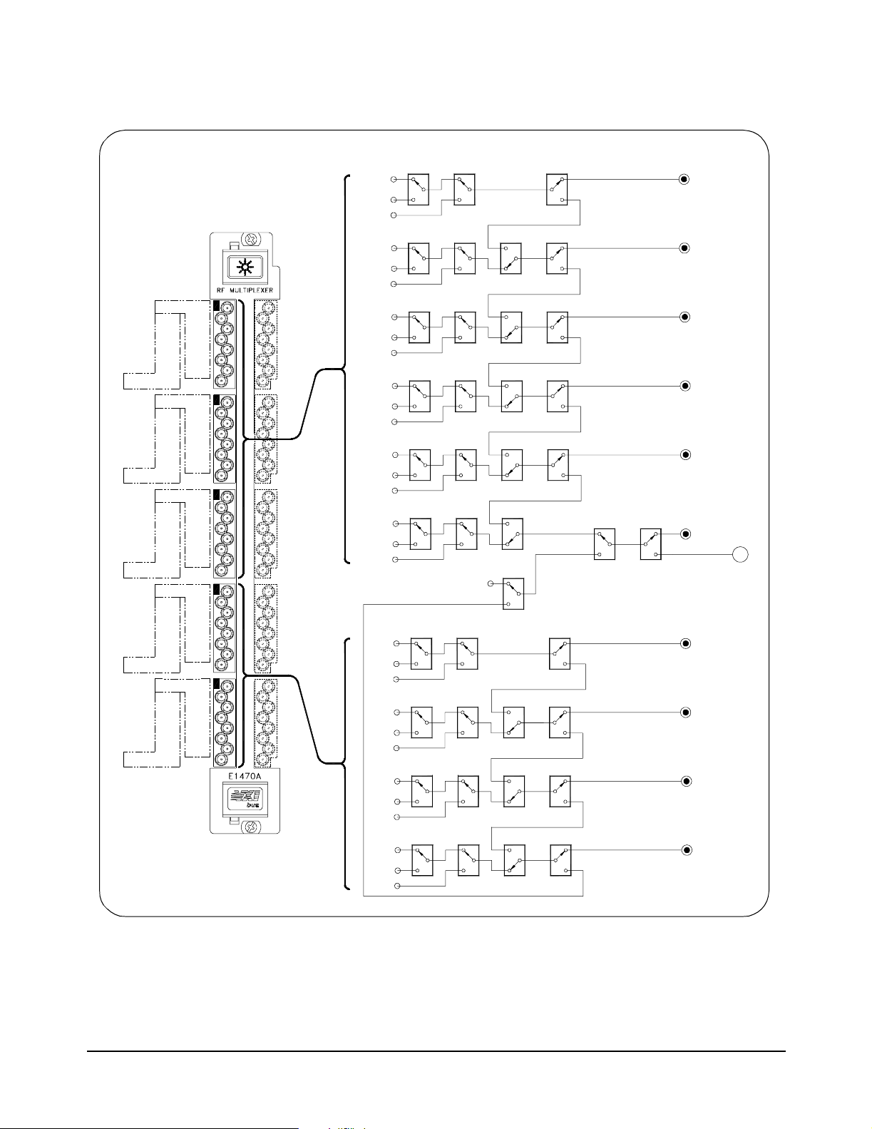
The E 1470A Cascade RF Switch module c onsists of a series of twenty
3-to-1 m ultiple xe rs. Each 3-to-1 multiplexer can be programatically
cascaded with other 3-to-1 multiplexers to form larger multiplexers. For
example, c ombining two adjacent multiplexers (cascading) forms a 6-to-1
multiplexer, casc ading three forms a 9-to-1 multiplexer, or cascading four
forms a 12-to-1 multiplexer, etc. Cascading all twenty 3-to-1 multiplexers
forms one 60-to-1 multiplexer.
Multiple combinations are simultaneously allowed on the module.
User connections t o the module are to SMB connectors on the faceplate.
Figure 1-2 shows the switching d iagram of the Cascade RF Switch module
with the switches s hown in the power-on/reset state.
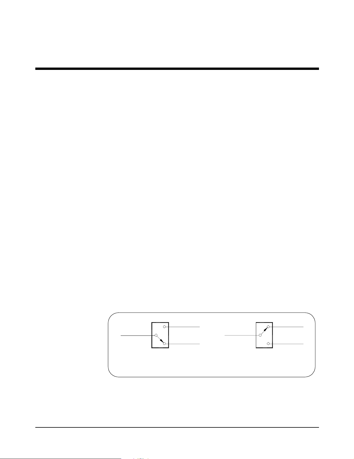
Since the relays on the switch are Form C, the relays are considered to
reset (or opened) when the COM MON terminal is connected to the NC
be
terminal (the power-on/reset state). Relays are c ons idered to be
closed) when the COMMON terminal is connected to the NO terminal.
See F igure 1-1.
NO
COMMON
NC
Form C Relay
Power-On/Reset
or Open State State
Figure 1-1. For m C Relays States
COMMON
Form C Relay
Set or Closed
set (or
NO
NC
Chapter 1
Configuring the RF Switch 9
Page 10
COM 00
010
002
011
001
012
COM 02
030
031
032
COM 04
050
051
052
COM 10
110
111
112
COM 12
130
131
132
000
022
021
020
042
041
040
102
101
100
122
121
120
COM 01
COM 03
COM 05
COM 11
COM 13
ChannelNumbers are in the form bbc where
bb i s the COM bank (00-05, 10-13, 20-25,or 30-33)
c is the individual number (0, 1, or 2).
Channel
Numbers
000
001
002
010
011
012
020
021
022
030
031
032
040
041
042
050
051
052
100
101
102
110
111
112
120
121
122
130
131
132
K001
K011 K012 K014
K021 K022 K024
K031 K032 K034
K041 K042 K044
K002 K003
K013
K023
K033
K043
K052K051
No Connection
12:1 Input
K101 K103
K111 K112
K121
K131
K102
K122
K132
K054
18:1
12:1
K055
K114
K124 K123
K134 K133
K113
Cascade Relays
K056
K053
COM 00
(3:1)
COM 01
(6:1)
COM 02
(9:1)
COM 03
(12:1)
COM 04
(15:1)
COM 05
(30:1)
Output
to Right-Side
Board
COM 10
(3:1)
COM 11
(6:1)
COM 12
(9:1)
COM 13
(12:1)
A
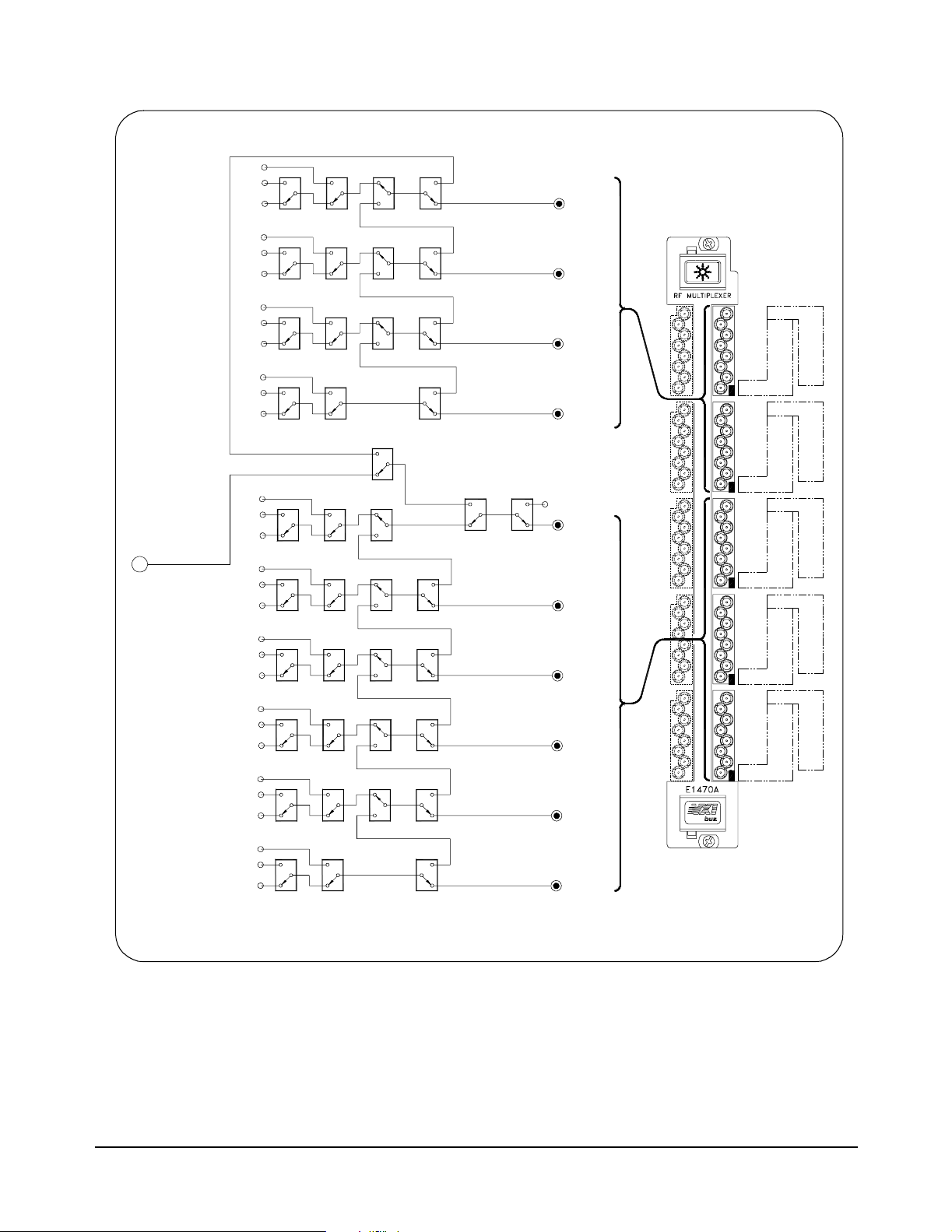
Figure 1-2. Cascad e RF Switch Switching Diagram (continued on next page)
10 Configuring the RF Switch
Chapter 1
Page 11
A
Channel
Numbers
332
331
330
K331
322
321
320
K321
312
311
310
K311
302
301
300
K301
252
251
250
(30:1)
Input
from Channels
0xx and 1xx
on Left-Side
Board
ChannelNumbers are in the form bbc where
bb is the COM bank (00-05, 10-13, 20-25, or 30-33)
c is the individualnumber (0, 1, or 2).
242
241
240
232
231
230
222
221
220
212
211
210
202
201
200
K251
K241
K231
K221
K211
K201
CascadeRelays
K332
K322
K312
K302
12:1 Input
30:1 Input
K252
K242
K232
K212
K202
K334
K324
K314
K255
K254
K244
K234
K214
K333
K323
K313
K303
12:1
(or 30:1)
18:1
K243
K233
K223K222 K224
K213
K203
K256
K253
COM 33
(12:1)
COM 32
(9:1)
COM 31
(6:1)
COM 30
(3:1)
No Connection
COM 25
COM 24
(15:1)
COM 23
(12:1)
COM 22
(9:1)
COM 21
(6:1)
COM 20
(3:1)
COM 32
COM 30
COM 24
COM 22
COM 20
COM 33
320
321
322
COM31
300
301
302
COM 25
240
241
242
COM 23
220
221
222
COM 21
200
201
202
332
331
330
312
311
310
252
251
250
232
231
230
212
211
210
Chapter 1
Figure 1-2. Cascade RF Switch Switching Diagram (continued)
Configuring the R F Switch 11
Page 12
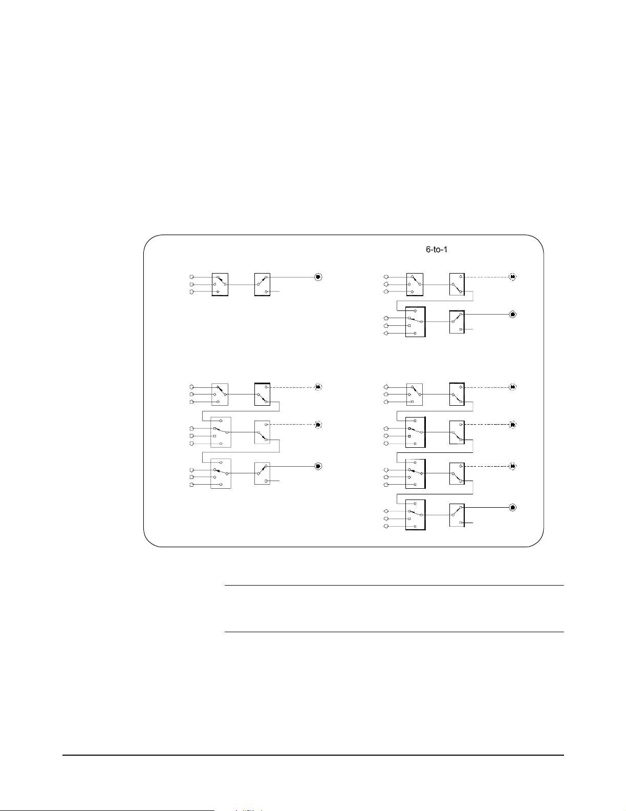
Creating Multiple Multiplexers
You can configure the Cascade RF Switch module to create multiple
multiplexers of varying sizes. In its power-on/reset state, the switch is
configured as 20 independent 3-to-1 multiplexers. Byspecifying a v alid path
from a COM terminal to a channel in adifferent bank (functionally c ascading
contiguous 3-to-1 multiplexe rs) other multiplexer sizes can be conf igured.
Figure 1 -3 shows typical 3-to-1, 6-to-1, 9-to-1, and 12-t o-1 multiplexers.
Other sizes can be configured by spec if y ing validROUTe:PATH statements
(see Chapter 2 for details). See Figure 1-2 for channel and COM numbering
information.
Channel
(BB)0
(BB)1
(BB)2
(BB)0
(BB)1
(BB)2
(BB+1)0
(BB+1)1
(BB+1)2
(BB+2)0
(BB+2)1
(BB+2)2
3-to-1
Multiplexer
9-to-1
Multiplexer
COM (BB)
COM (BB+2)
(BB)0
(BB)1
(BB)2
(BB+1)0
(BB+1)1
(BB+1)2
(BB)0
(BB)1
(BB)2
(BB+1)0
(BB+1)1
(BB+1)2
(BB+2)0
(BB+2)1
(BB+2)2
(BB+3)0
(BB+3)1
(BB+3)2
Multiplexer
COM (BB+1)
12-to-1
Multiplexer
COM (BB+3)
NOTE Generally, the CO M terminal is on the highest-numbered bank. Exceptions
12 Configuring the RF Switch
Figure 1-3. Creating Multiple Multiplexers
are that channels 100 through 132 can go to COM 05 as well as to COM 13
and channels 300 through 332 can go to COM 25 as wel l as to COM 33.
For example, COM 01 can be used as the common for channels 000 - 002
and 010 - 012 creat ing a 6-to-1 mult iple xer. COM 11 can be the common
forchannels 100 - 102 and 110 - 112 for another 6-to-1 multiplexer. COM 02
can be common for channels 000 - 002, 010 - 012, and 020 - 022 for a 9-to-1
multiplexer. COM 03 c an be the common for channels 000 - 002, 010 - 012,
020 - 022, and 030 - 032 for a 12-to-1 m ultiplexer.
Chapter 1
Page 13

COM 04 can be used for a 15-to-1 multiplexer for all channels between 000
and 042. COM 05 can be the common for al l channelsfrom 000 t hrough 052
creating an 18-to-1 multiplexer. M ult ipl ex ers of 21-to-1,24-to-1,and 27-to-1
can a lso be c onf igured. Two 30-to-1 multiplexers can be creat ed using
channels 00 through 132 to COM 05 and channels 200 through 332 to
COM 25. One 60-to-1 multiplexer c an be created us ing all the channels
to CO M 25.
RF Switch Configuration
This s ec tion gives guidelines to configure the RF Switch module, including:
• Warnings and Cautions
• Select ing the Logical Ad dress
• Setting the Interrupt Request Level
• Connecting User Wiring
Warnings and
Cautions
WARNING SHOCK HAZARD. Only service-trained personnel who are
aware of the hazards involved should install, remove, or
configure the module. Before you remove any installed
module, disconnect AC power from the mainframe and from
other modules that may be connected to the module.
WARNING CHANNEL WIRING INSULATION. All channels that have a
common connection must be insulated so that the user is
protected from electrical shock in the event that two or more
channels are connected together. This means wiring for all
channels must be insulated as though each channel carries
the voltage of the highest voltage channel.
CAUTION MAXIMUM POWER. The maxim um RF power t hat can be appli ed
to the module is 10 Watts RF. Do not apply line AC power to any terminal
on this module.
CAUTION STATIC ELECTRICITY. Static electricity is a major cause of component
failure. To prevent damage to the electrical components in the module,
observe anti-static techniques whenever removing a module from the
mainframe or working on a module.
Chapter 1
Configuring the R F Switch 13
Page 14
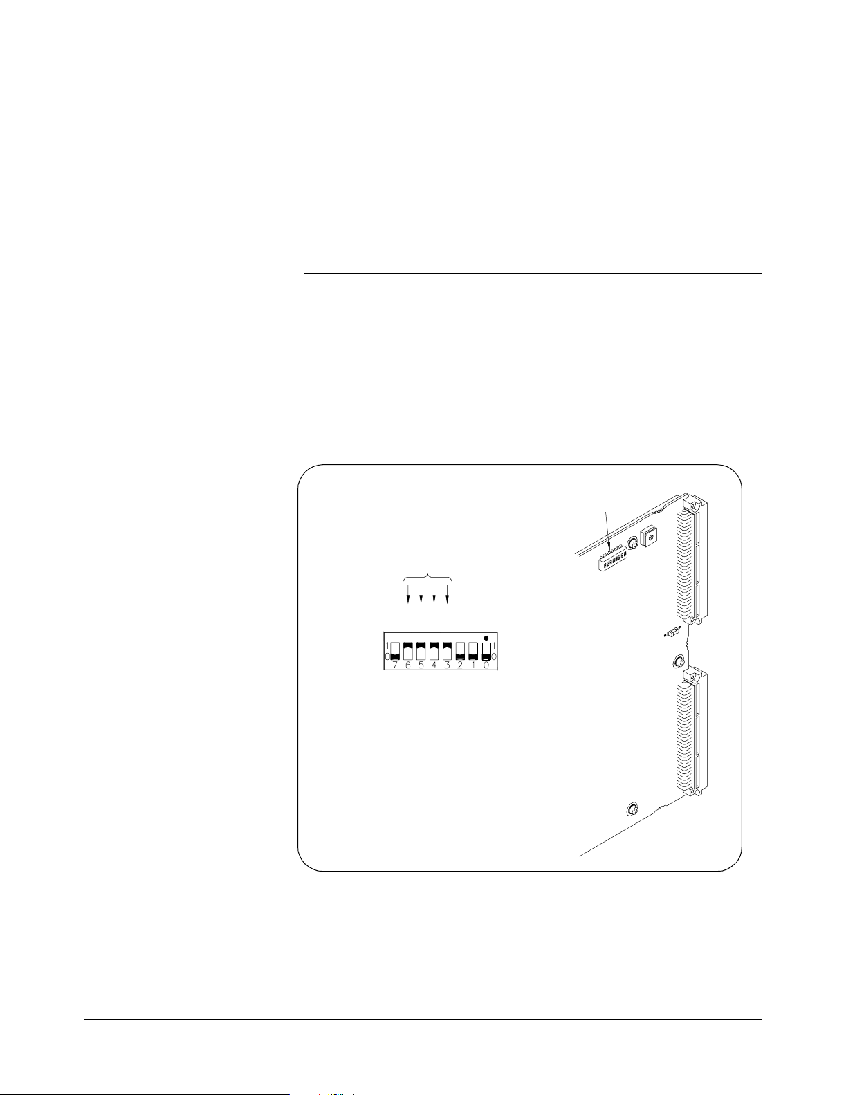
Setting the Logical
Address
NOTE When using the Cascade RF Switch module with an E1406 Command
Thelogicaladdress of the Cascade RF Switch module is set with the Logical
Address (LA DDR) switch on the module. The logical address is factory-set
to120.Valid address es are from 1 to 256. See Figure 1-4 for address switch
settings.
The logical address is the sum of the values of the switches set to the
CLOSED position. In F igure 1-4,switches 3 through 6 are CLOSED andthe
associated values of these switches are 8, 16, 32, and 64. Thus, the logical
address = 8 + 16 + 32 + 64 = 128.
Module, t he address must be a multiple of 8 (for example, 8, 16, 24,...
112, 120, 128, . .. 240, 248). The module cannot be configured as part
of a multiple-module switchbox instrument.
If the Logical Address Switches are set for 255, the System Res ourc e
Manager automatically ass igns a Logical Address to the module. You c an
poll the Resource Manager to determine the logical address assigned tothe
module.
Logical Address
Switch Location
64+32+16+8=120
8
6
2
4
2
1
8
3
6
1
1=CLOSED
0=OPEN
CLOSED = Switch Set To 1 (ON)
OPEN = Switch Set To 0 (OFF)
2
4
1
Logical Address = 120
Figure 1-4. Setting the Lo gical Address Switch
14 Configuring the RF Switch
Chapter 1
Page 15
Setting the Interrupt
Request Level
NOTE Interrupts can also be disabled using the Control Register (see Appendix
Interruptsare enableda t power-up,aftera SYSRESET,ora fterresettingthe
module via the Control Register (see Appendix B). If interruptsare enabled,
the system generates an interrupt after writing to any relay cont rol register.
Theinterrupt is generated approximately 13msecafter writing to theregister
to indicate the end of relay closure/settling time.
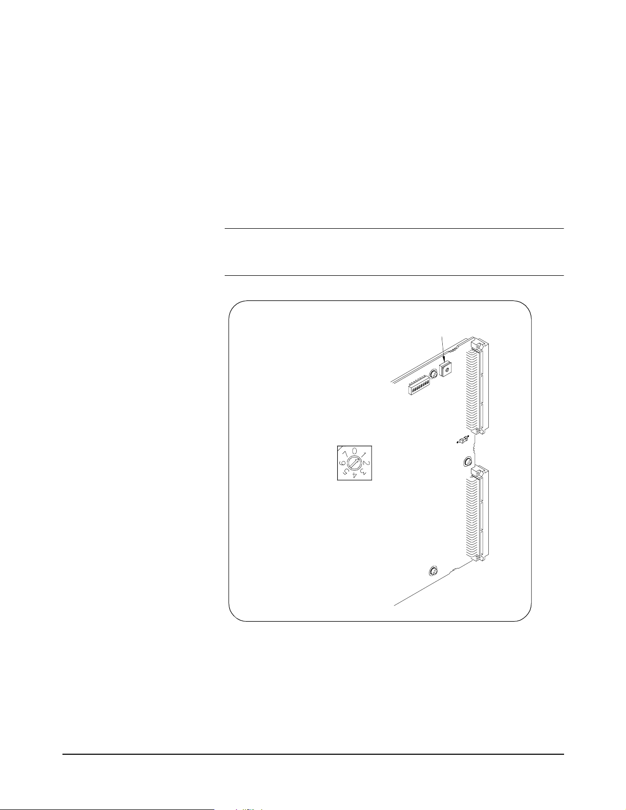
As s hown in Figure 1-5, the Interrupt Request Level switch selects the
priority level that will be asserted. The Interrupt Re quest Level sw itch is set
in posit ion 1 as shipped from the factory. For most applications this priority
level should not be changed. The interrupts are disabl ed when set to
position 'X'. To c hange the setting, set the switch to the level required.
B). Also, consult your mainframe manual to make s ure backplane
jumpers/switches are configured correctly.
Interrupt request Level
Rotary Switch Location
Interrupt Request (IRQ)
Level 0 = Interrupt Disabled
Figure 1-5. Setting the Interrupt Requ est Level Switch
Chapter 1
Configuring the R F Switch 15
Page 16
Connecting User
Wiring
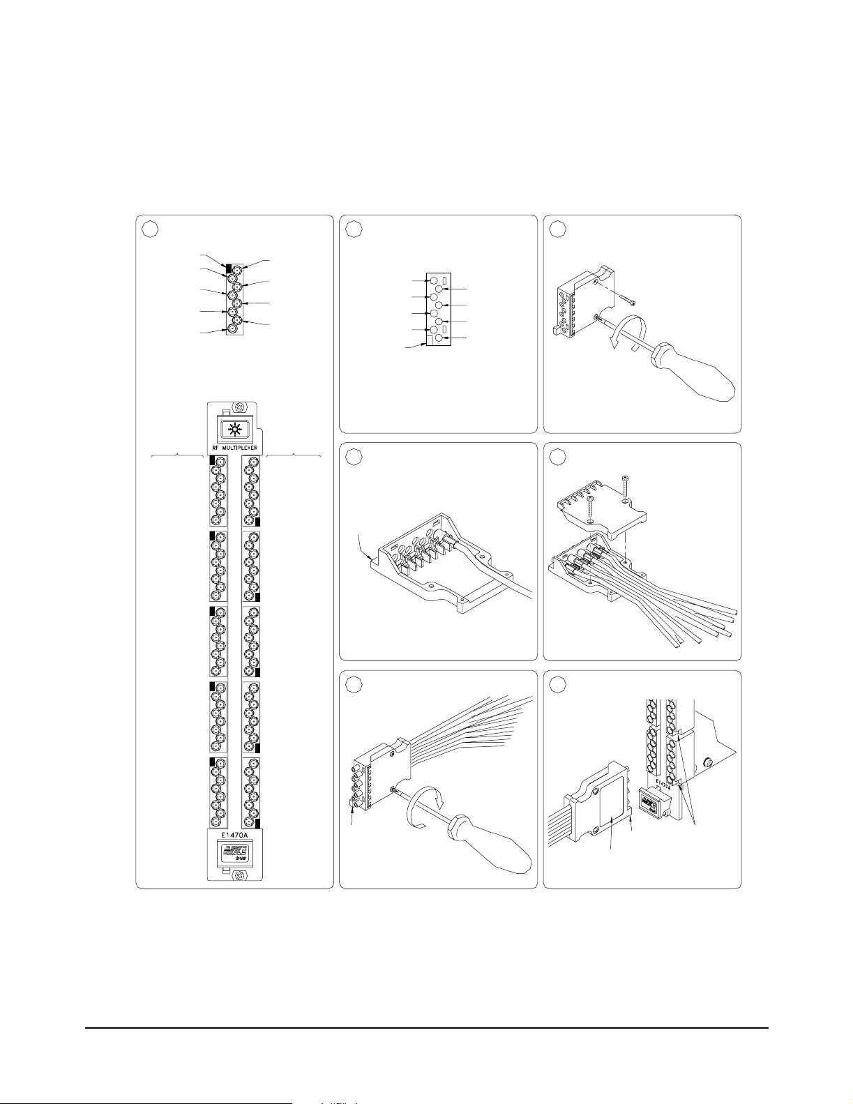
User wi ring connections to the module are via multiple connector bloc k s
(part num ber 1250-2563). Figure 1-6 shows how to wire and assemble th e
connector housing. See “Cables and Connectors” for guidelines to
assemble SMB jacks and connectors. Se e Table 1-2 in “User Wiring Log”
for a log to record your wiring configuration.
Identify ConnectorPinout
1
Key
Channel
(BB+1)0
Channel
(BB+1)1
Channel
(BB+1)2
COM(BB+1)
BB=Bank Number:
00, 01, 02, 03, 04, 05
10, 11, 12, 13
20, 21, 22, 23, 24, 25
30, 31, 32, 33
Channel
Numbers
COM 00
010
002
011
001
012
000
COM 01
COM 02
030
022
031
021
032
020
COM03
COM 04
050
042
051
041
052
040
COM05
COM 10
110
102
111
101
112
COM 11
COM 12
130
122
131
121
132
120
COM13
COM(BB)
Channel
(BB)2
Channel
(BB)1
Channel
(BB)0
Channel
Numbers
320
321
322
COM 32
300
301
302
COM 30
240
241
242
COM 24
220
221
222
COM 22
200
201
202
COM 20
COM 33
332
331
330
COM 31
312
311
310
COM 25
252
251
250
COM 23
232
231
230100
COM 21
212
211
210
Identify ConnectorHousing
2
Pinout
COM(BB+1)
(BB+1)2
(BB+1)1
(BB+1)0
Key
BB=Bank Number:
00, 01, 02, 03, 04, 05
10, 11, 12, 13
20, 21, 22, 23, 24, 25
30, 31, 32, 33
4
Install Field Wiring
Key
6
ReplaceScrews
Key
(BB)0
(BB)1
(BB)2
COM(BB)
Remove Screws3
Close Shell5
Install Connectors on Module7
A Label
Can Be
Placed Here
Key
Key
Hole
Guide
16 Configuring the RF Switch
Figure 1-6. Installing User Wiring
Chapter 1
Page 17
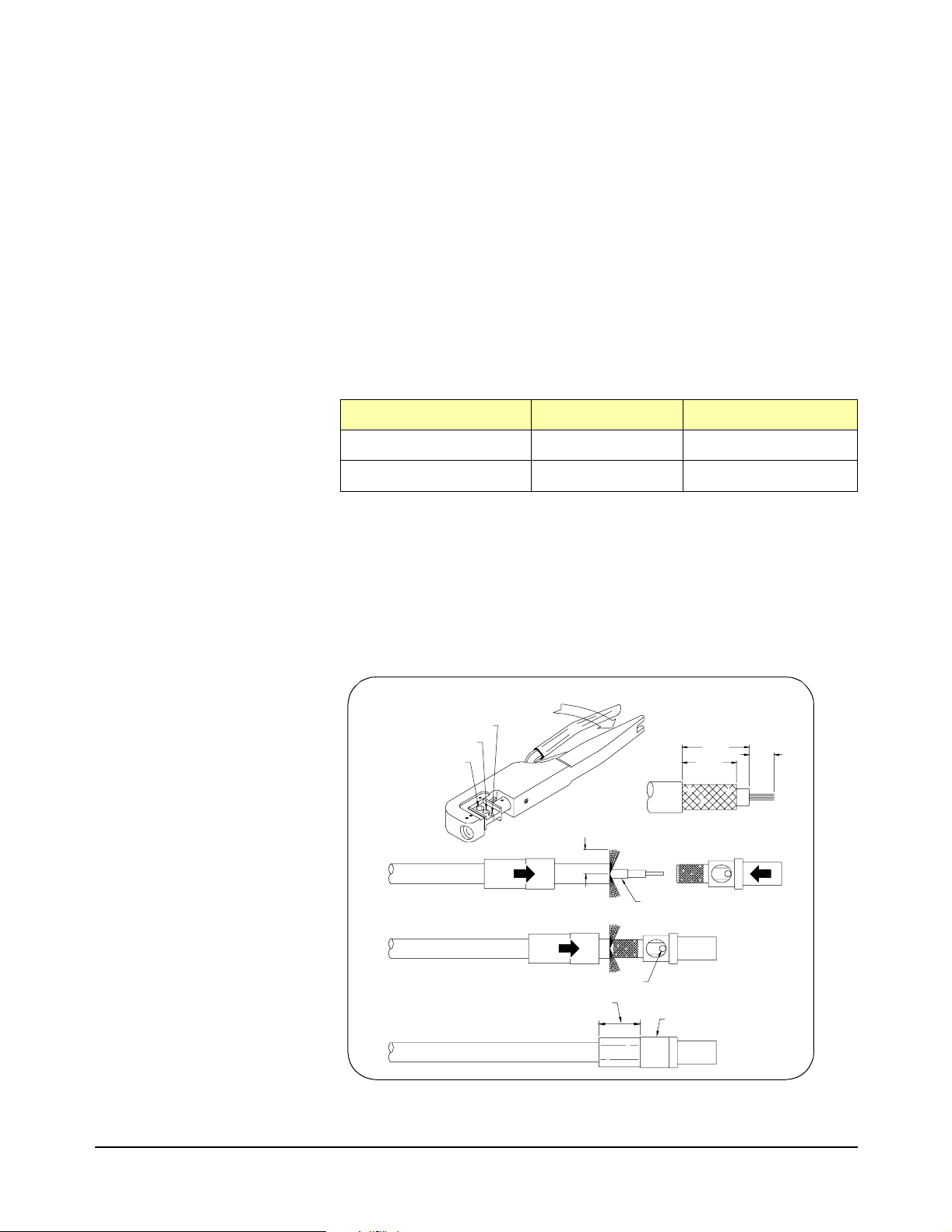
Cables and Connectors The Cas c ade RF Switch module is shipped with a kit of 85 SMB connector
jacks and 10 connector housings. You mus t supply your own 50Ω
double-shielded cable (single-shielded cable can also be used). Agilent
recommends RG188DS or RS 316DS double-shielde d cables or
triple-shielded cable (part number 8120-0552).
Standard S MB connector jacks will fit into the Cascade RF Switch module
connector sockets and may be used if adjacent sockets on the module are
NOT us ed. However, the outside diameter of the standard SMB jacks
prohibits using them on thec losely spaced, adjacent sockets on t he module
and they will not fit in th e connector housing. Special jacks with a smaller
shoulder must be used if adjacent sockets on the module are used. See
Table 1-1.
Table 1-1. SMB Connectors and Connector Housings
Description Quantity Part Number
SMB Jacks* Package of 8 E1470-22101
Connector Housing Individual 1250-2563
* Single SMB jacks are availablefrom E. F. Johnson Co. by part number
131-4304-011/020.
Assembling SMB
Connector Jacks
Figure 1-7 shows how to assem ble the SMB connector jack s. Jacks for
double-shielded cable require a 0.151 hex crimp about 0.260 wide.
Individual jacks for single-shielded RG188 and RG31 6 cable are avai lable
from E. F. Johnson Co (part number 131-4303-011/020) and require a hex
crimp s ize of 0.128.
"C" Hex Setting
"B" Hex Setting
"A"Hex Setting
.200
Foil Inside If Using 8120-0552
Solder
Crimp With 452301-B Die (0.151 Hex Crimp)
.245
.200
Don't Crimp Here
.094
Chapter 1
Figure 1-7. Assem bling SMB Jacks and Cables
Configuring the R F Switch 17
Page 18

User Wiring Table Table 1-2 prov ides a log for you to document wiring to t he Cascade RF
Switch module. See Figure1-1 for terminal identification. See Figure 1-6 for
guidelines to connect user wiring. You can copy t he table as desired.
Table 1-2. User Connections Wiring
Term Connected to: Term Connected to: Term Connected to:
COM 00 COM 11 COM 24
CH 0 02 CH 110 CH 240
CH 0 01 CH 111 CH 241
CH 0 00 CH 112 CH 240
COM 01 COM 12 COM 25
CH 0 10 CH 122 CH 252
CH 0 11 CH 121 CH 251
CH 0 12 CH 120 CH 250
COM 02 COM 13 COM 30
CH 0 22 CH 130 CH 300
CH 0 21 CH 131 CH 301
CH 0 20 CH 132 CH 302
COM 03 COM 20 COM 31
CH 0 30 CH 200 CH 312
CH 0 31 CH 201 CH 311
CH 0 32 CH 202 CH 310
COM 04 COM 21 COM 32
CH 0 42 CH 212 CH 320
CH 0 41 CH 211 CH 321
CH 0 40 CH 210 CH 320
COM 05 COM 22 COM 33
CH 0 50 CH 220 CH 332
CH 0 51 CH 221 CH 331
CH 0 52 CH 222 CH 330
COM 10 COM 23
CH 1 02 CH 232
CH 1 01 CH 231
CH 1 00 CH 230
18 Configuring the RF Switch
Chapter 1
Page 19

Programming the RF Switch
Using This Chapter
This chapter gives guidelines to program the Cascade RF Switch module
(RF S witch) including:
• InstallingDeviceDrivers..............................19
• AddressingtheSwitch...............................20
• ProgrammingExamples..............................21
Installing Device Drivers
Before you can use the Cascade RF Switchmodule, yo u may need toinstall
device drivers. The type of driver(s) to be installed depend on whether you
use an E1406 Command Module or another type of com mand module. The
two ty pes of drivers applicable to the RF Switch module are VXIplug&play
Instrument Drivers (installed on your PC) a nd SCPI Instrument Drivers
(downloaded into the E1406 Command Module).
Chapter 2
NOTE It is highly recommended the SCPI Instrument driver be installed whether
the VX I instrument is program med using its VXIplug&play driver or using
SCPI commands embedded in an I/O language. For the latest information
on drivers, see the Agile nt Web S ite:
http://www.agilent.com/find/inst_drivers
To download th e SCPI Instrument Dri ver into the E1406A Command
Module, you will need to usethe VXI Installation Consultant (VIC) contained
on the Agilent Technologies Universal Instrument Drivers CD. To download
the driver, install the CD in your CD-ROM drive and follow the installation
instructions. The setup program should run automatically. If it does not,
Start | Run
click
where <drive> is the letter for your CD-ROM drive.
NOTE To download a driver, the ROM v ers ion number of the E1406 Command
Module must be A.06.00 or above . To determine the version number, send
the IEEE 488.2 common command *IDN?. A typical return v alue follows,
where A.06.01 is the vers ion number.
and type
HEWLETT-PACKARD,E1406A,0,A.06.01
<
drive
>:SETUP.EXE
in the command line,
Chapter 2
Programming the RF Switch 19
Page 20

Addressing the Switch
By s pecifying a path destination (a COM number) and a source (a channel
number), a channel is conn ec ted to a COM terminal. The format for
addressing the switch is
where <
channel
and <
0s can be omitted.) See the
Chapter 3 for valid <
[ROUTe:]PATH[:CO MMon ] <
comm
> is a 2-digit number s pec ifying the bank for the COM terminal
> is a 3-digit number specifying a channel number. (Leading
[ROUTe:]PATH[:COMMon]
comm
> and <
channel
> numbers.
comm
>, <
command in
channel
>
You can use
whether a path is closed (returns a 1) or is open (returns a 0). You can
use the PATH statement to create multiple 3-to-1 multiplexers, 6-to-1
multiplexers, 9-to-1 multiplexers, 12-to -1 multiplexers, etc. Up to two
30-to-1 multipl ex ers or one 60-to-1 multiplexer can be configured. For
example, the following statements each connect a COM terminal to a
channel.
PATHCOMM 00,001
PATHCOMM 04,020
PATHCOMM 05,002
Using invali d numbers for
When switching a signal path, only the relays necessary to complete the
path are switched. All other relays remain in their current state. This
prevents unexpected switching results. However, when closing one sig nal
path, another signal path might
[ROUTe:]PATH[:COMMon]? <
<
comm
>
and
open. For example:
comm
>, <
channel
!Connects COM 00 to Channel 001,
!COM 00 is common to channels 000,
!001, 002; forming a 3-to-1 mux.
!Connects COM 04 to Channel 020,
!COM 04 is common to channels 020
!through 042; forming a 9-to-1 m ux .
!Connects COM 05 to Channel 002,
!COM 05 is common to channels 000
!through 052 forming an 18-to-1 mux.
<
channel
>
will generate an error.
>
to indicate
20 Prog ramming the RF Switch
PATHCOMM 01,010
PATH COMM? 01,010
PATHCOMM 02,002
PATH COMM? 01,010
!Closes a signal path from COM 01
!to C hannel 0 10.
!Returns "1" indicating the path is
!closed.
!Closes a signa l path from COM 02 to
!Channel 002 and changes the state
!of the cascade relay, opening t he
!prior signal pat h.
!Returns "0" indicating the path is
!open.
Chapter 2
Page 21

Programming Examples
The following C-language programs show one way to verify initial operation
for the Cascade RF Switch mod ule, to close signal paths, and to save and
recall module sta tes. To run these programs, you must have installed the
E1470A S C P I Device Driver, Agilent IO Libraries for Windows,andaGPIB
module in your PC.
Example: Module
Self-Test
NOTE
This program:
• Identifies the module and device driver
• Resets the module
• Closes a path (source/destination)
• Verifies that the path is closed
• Exe cutes the module self-test
The
*RST
command performs a device reset on the module and sets it to
its power-on state. (Saved module states and status information are not
*RST
.) The
*TST?
affected by
match the configurations programmed using the
*TST?
DIAG:CLOS orDIAG:OPEN
should be a "0". Any other value indicates the actual state of the relays do
not m at ch the configuration programmed by the
See Chapter 3 for details.
/*
This program resets the E1470A, reads the ID string, performs a
self-test, reads any self-test error messages, and closes and verifies
a signal path
results are unpredictable if you use register -based programming or
Self -Test.
*/
command verifies that the relay pos itions
ROUT:PATH
to cont ro l individual relays. The value returned
ROUT:PATH
commands.
command.
Chapter 2
#include <visa.h>
#include <stdio.h>
#include <stdlib.h>
void err_handler();
void main()
{
char buff[256] = {0};
int err_no, ch_closed;
/*
Create and Open a Device Session. E1470 is at logical address 120
ViStatus err;
ViSession defaultRM,rf_mux;
viOpenDefaul tR M (&defaultRM);
viOpen (defaultRM, " G PIB -VXI0 ::9::12 0 " ,V I _N UL L , VI _ NU L L, &rf_ mux );
Programming the RF Switch 21
*/
Page 22

/*
Reset the E1470A
err= viPrintf (rf_mux , "* R ST;*CL S;*O PC? \n');
if (err < VI SUCCESS) err_handler (rf_mux,err);
err= viScanf (rf_mux,"%s",&buf);
if (err < VI_SUCCESS) err_handler (rf_mux,err);
/*
Read and display the ID String
HEWLETT-PACKAR D, E1470A,0,A.01.00 */
err = viPrintf (rf_mux "*IDN?\n');
if (err < VI_SUCCESS) err_handler (rf_mux,err);
err= viScanf (rf_mux,"%s",&buf);
if (err < VI_SUCCESS) err_handler (rf_mux,err);
printf ("Module Identification String: %s\n",buf);
/ *
Do the Self Test
printf ("Performing the Self Test\n");
err= viPrintf (rf_mux,"*TST?\n');
if (err < VI_SUCCESS) err_handler (rf_mux,err);
err = viScanf (rf_mux,"%d",&err_no);
while (err < VI_SUCCESS) err = viScanf (rf_mux,"%d",&err_no);
if (err no != 0) printf ("\nSelf Test Error: %d\n",err_no);
else printf ("\nNo Self Test Errors");
*/
. Should return
*/
/*
Close a signal path from COM 02 to Channel 002
err= ViPrintf (rf_mux,"PATH:COMM 02,002\n");
if (err < VI_SUCCESS) err_handler (rf_mux,err);
/*
Verify the path is closed
err = viPrintf (rf_mux,"PATH: COMM? 02,002\n');
if (err < VI_SUCCESS) err_handler (rf_mux,err);
err= viScanf (rf_mux,"%d",&ch_closed);
if (err < VI_SUCCESS) err_handler (rf_mux,err);
if (ch_closed ==1) printf ("Signal path is closed");
else printf ("Signal path is NOT closed");
/*
Close Session
viClose (rf_mux);
viClos e (defaultRM);
}
void err_handler() /*
{
ViStatus err;
char err_msg[1024]={0};
viStatusDesc(rf_mux,err,err_msg);
printf ("Error = %s\n",err_msg);
return;
}
*/
*/
Error handling routine
*/
*/
22 Prog ramming the RF Switch
Chapter 2
Page 23

Example: Closing a
Signal Path
This program example closes a signal path from COM 01 to channel 010
and verifies that the path is closed.
#include <visa.h>
#include <stdio.h>
#include <stdlib.h>
void err_handler();
void main()
{
int ch_closed;
/*
Create and open a device session, E1470 is at logical address 120
ViStatus err;
ViSession defaultRM,rf_mux;
ViOpenDefaul tR M (&defaultRM );
viOpen (defaultRM, " G PIB -VXI0 ::9::12 0 " ,V I _N UL L , VI _ NU L L, &rf_ mux );
/*
Close a path from COM 01 to channel 010
err= viPrintf (rf_mux,"PATH:COMM 01,011\n");
if (err < VI_SUCCESS) err_handler (rf_mux,err);
*/
*/
/*
Verify the path closure
err = viPrintf (rf_mux,"PATH:COMM? 01,011\n");
if (err < VI_SUCCESS) err_handler (rf_mux,err);
err = viScanf (rf_mux,"%d",&ch_closed);
if (err < VI_SUCCESS) err_handler (rf_mux,err);
if (ch_closed == 1) printf ("Signal path is closed");
else printf ("Signal path is NOT closed");
/*
Close the session
viClose (rf_mux);
viClos e (defaultRM);
}
void err_handler() /*
{
ViStatus err;
char err_msg[1024]={0};
viStatusDesc(rf_mux,err,err_msg);
printf ("Error = %s\n",err_msg);
return;
}
*/
*/
Error handling routine
*/
Chapter 2
Programming the RF Switch 23
Page 24

Example: Opening
and Closing Signal
Paths
This program first closes a signal path from COM 01 t o channel 011 and
verifies that the path is closed. Next, the program closes a signal path from
COM 02 to channel 010 (which opens the COM 01 to channel 011 path).
Then, the program verifies t hat the COM 02 to channel 010 path is closed
and the COM 01 to channel 011 path is open.
#include <visa.h>
#include <stdio.h>
#include <stdlib.h>
void err_handler();
void main()
{
int ch_closed;
/*
Create and open a device session. E1470 is at logical address 120
ViStatus err;
ViSession defaultRM,rf_mux;
viOpenDefaul tR M (&defaultRM);
viOpen (defaultRM, " G PIB -VXI0 ::9::12 0 " ,V I _N UL L , VI _ NU L L, &rf_ mux );
/*
Close a path from COM 01 to channel 011
*/
*/
err= viPrintf (rf_mux,"PATH: COMM 01,011\n");
if (err < VI_SUCCESS) err_handler (rf_mux,err);
/*
Verify path closure
err= viPrintf (rf_mux,"PATH:COMM? 01,011\n");
if (err < VI_SUCCESS) err_handler (rf_mux,err);
err= viScanf (rf_mux,"%d",&ch_closed);
if (err < VI_SUCCESS) err_handler (rf_mux,err);
if (ch_closed == 1) printf ("Signal path 01,011 is closed");
else printf ("Signal path 01,011 is NOT closed");
/*
Close a second signal path COM02 to channel 010
err = viPrintf (rf_mux,"PATH:COMM 02,01\n");
if (err < VI_SUCCESS) err_handler (rf_mux,err);
/*
Verify the path closure
err= viPrintf (rf_mux,"PATH:COMM? 01,011\n");
if (err < VI_SUCCESS) err_handler (rf_mux,err);
err= viScanf (rf_mux,"%d",&ch_closed);
if (err < VI_SUCCESS) err_handler (rf_mux,err);
if (ch_closed == 1) printf ("Signal path 01,011 is closed");
else printf ("Signal path 01,011 is NOT closed");
*/
*/
*/
24 Prog ramming the RF Switch
Chapter 2
Page 25

err= viPrintf (rf_mux,"PATH:COMM? 02,01\n");
if (err < VI_SUCCESS) err_handler (rf_mux,err);
err = viScanf (rf_mux,"%d",&ch_closed);
if (err < VI_SUCCESS) err_handler (rf_mux,err);
if (ch_closed == 1) printf ("Signal path 02,010 is closed");
else printf ("Signal path 02,010 is NOT closed");
/*
Close the session
viClose (rf_mux);
viClos e (defaultRM);
}
void err_handler() /*
{
ViStatus err;
char err_msg[1024]={0};
viStatusDesc(rf_mux,err,err_msg);
printf ("Error = %s\n",err_msg);
return;
}
*/
Error handling routine
*/
Example: Saving
and Recalling
Module States
The
*SAV
command saves the c urrent state of all relays on the Cascade
RF Switch module an d thus all the signal path connection s. You can use
*SAV
to sav e up to ten module states and then use the
return to a specific saved state.
The c ommands have the form
range of 0 to 9. Error -222, “Data out of range” results if a value other than
0 through 9 is used for
This example program first creates several PATH co nfigurations and saves
that module state as state number 1. Next, the program creates additional
paths (while the previous paths remai n closed) and saves that state a s
state 2. Then, the program resets the module and recalls module s tate
number 1.
#include <visa.h>
#include <stdio.h>
#include <stdlib.h>
void err_handler();
void main()
{
int ch_closed;
<n>
*SAV<n>
.
and
*RCL<n>
*RCL
where
command to
<n>
has a
Chapter 2
/*
Create and open a device session. E1470 is at logical address 120
ViStatus err;
ViSession defaultRM,rf_mux;
viOpenDefaul tR M(&defaultR M);
viOpen (defaultRM, " G PIB -VXI0 ::9::12 0 " ,V I _N UL L , VI _ NU L L, &rf_ mux );
Programming the RF Switch 25
*/
Page 26

/*
Close multiple signal paths and save as state number 1
err = viPrintf (rf_mux,"PATH:COMM 01,011;:PATH:COMM
13,100;:PATH:COMM 31,301\n");
if (err < VI_SUCCESS) err_handler (rf_mux,err);
err = viPrintf (rf_mux,"*SAV 1 \n");
if (err < VI_SUCCESS) err_handler (rf_mux,err);
/*
Close additional signal paths and save as state number 2
err= viPrintf (rf_mux,"PATH:COMM 02,010;:PATH:COMM 22,202;:
PATH:COMM 24,232\n");
if (err < VI_SUCCESS) err_handler (rf_mux,err);
err = viPrintf (rf_mux,"*SAV 2\n");
if (err < VI_SUCCESS) err_handler (rf_mux,err);
/*
Reset the module
err = viPrintf (rf_mux, "* R ST;*CL S:OPC? \n" );
if (err < VI_SUCCESS) err_handler (rf_mux,err);
err = viScanf (rf_mux,"%d",&ch_closed);
if (err < VI_SUCCESS) err_handler (rf_mux,err);
*/
*/
*/
/*
Recall state number 1
err= viPrintf (rf_mux , "* R CL 1\n");
if (err < VI_SUCCESS) err_handler (rf_mux,err);
/*
Verify that a signal path from state number 1 is closed
err = viPrintf (rf_mux,"PATH:COMM? 01,011\n");
if (err < VI_SUCCESS) err_handler (rf_mux,err);
err = viScanf (rf_mux,"%d",&ch_closed);
if (err < VI_SUCCESS) err_handler (rf_mux,err);
if (ch_closed == 1) printf ("Signal path 01,011 is closed");
else printf ("Signal path 01,011 is NOT closed");
/*
Close session
viClose (rf_mux);
viClos e (defaultRM);
{
void err_handler() /*
{
ViStatus err;
char err_msg[1024]={0};
viStatusDesc(rf_mux, err, err_msg);
printf ("Error = %s\n",err_msg);
return;
}
*/
*/
Error handling routine
*/
*/
26 Prog ramming the RF Switch
Chapter 2
Page 27

RF Switch Command Reference
Command Types
Chapter 3
This chapter des cribes Standard Commands for Programmable
Instruments (SCPI) and summarizes IEEE 488.2 Common (*)
Commands applicable to the E1470A Cascade RF Switch Module.
Commands are separated into two types: IEEE 488.2 Com mon
Commands and SCPI Commands.
Common
Commands Format
SCPI C ommands
Format
The IEEE 488.2 standard defines the Common Commands that perform
functions likeres et, self-test, status byte query, etc.Common commands
are four or five characters in length, always begin with the asterisk
character (*), and may include one or more param eters. The command
keyword is separated from the first parameter by a space character.
Some examples of Common Commands are:
*RST *ESR 32 *STB?
SCPI commands perform functions like closing switches, querying
instrument states, or retrieving data. A subsystem command structure is
a hierarchical structure that usually consists of a top level (or root)
command, one or more lower level commands, and their parameters.
The following example shows part of a typical subsystem:
[ROUTe:]PATH[:COMMon] <comm>,<channel>
[ROUTe:] is the (optional) r oot c ommand, PATH is the second level
command, and [:COMMon] i s a third level (optional) command.
<comm>,<channel> are command parameters.
Command Separator Acolon(:) a lways separates one command f rom the next lower level
command as shown below. Colons separate t he root command from the
second level command (ROUTe:PATH) and t he second level from the
third level (PATH:COMMon).
ROUTe:PATH:COMMon
Abbreviated Commands The command syntax s hows most commands as a mixture of upper and
lower c as e letters. The upper case letters indicate the abbreviated
spelling for the command. For shorter program lines, send the
abbreviated form. For better program readability, you may send the
entire com mand. The instrument will accept either the abbreviated form
or the entire command.
Chapter 3
RF Switch Command Reference 27
Page 28

For ex ample, if the command syntax shows MEASure, then M E AS and
MEASURE areboth acceptable forms. Other formsof MEA Sure, such as
MEASU or MEASUR will generate an error. Y ou may use upper or lower
case letters. Therefore, MEASURE, me asure, and MeAsUrE are all
acceptable.
Implied Commands Impli ed commands are those which appear in square brackets ([ ]) in the
command syntax. (Theb rackets are not part ofthe comm and and are not
sent to the instrument.) Suppose you send a second level command but
do not send the preceding implied command. In this case, theinstrument
assumes you intend to use the implied command and it responds as if
you had sent it. Examine the [ROUTe:] subsystem shown below:
[ROUTe:]
PATH[:COMMon] <comm>,<channel>
PATH[:COMMon]? <comm>,<cha nnel>
The root command ROU Te: is an impli ed command as is the command:
COMMon. To clo se a signal path, you can send any of the following
command statements:
PATH 2,1
ROUT:PATH 2,1
PATH:COMM 2,1
ROUT:PATH:COMM 2,1
These com mands function the same , connecting the COMMON in bank
02 to channel 1 in bank 00. For information on channel and bank
numbers, see Chapter 2.
Parameters Parameter Types. The ROUTe:PATH com mand accepts only numeric
parameters.
Linking Commands Linking IEEE 488.2 Common Commands with SCPI Commands. Use a
semicolon between the commands. For example RS T; ROUT:PATH 2
or ROUT:PATH 2,1 ;*SAV 1
Linking Multiple SCPI Commands. Use both a semicolon and a colon
between the commands . For example, ROUT:PATH 2, 1;:PAT H 3,32
SCPI Command Reference
This s ec tion describes the Standard Commands for Programma ble
Instruments (SCPI) commands for the E1470A Cascade RF Switch
module. Comman ds are listed alphabe tically in by subsystem and within
each subsystem.
28 RF Switch Command Reference
Chapter 3
Page 29

DIAGnostic
Subsystem Syntax DIAGnostic
DIAGnostic:CLOSe
The DIA Gnost ic subsystem cont ains instrument-specific com m ands is
are not recommended for general pro gramm ing. For the E1470A, the
DIAG subsystem allows you to open/close individual relays and query
individual relays.
:CLOSe <relay>{,<relay>...}
:CLOSe? <relay>{,<relay>...}
:OPEN <relay>{,<relay>...}
:OPEN? <relay>{,<relay>...}
:RELAY?
DIAGnostic:CLOSe <relay>{,<relay>...} closes individual relays on the
E1470A. Since these are Form C relays, “closed” means the relay is“set”
(COMMON to NO).
Parameters
Name Type Range of Values
<relay> numeric 001-003|011-014|021-024|031-034|041-044|
051-056|101-103|111-114|121-124|131-134|
201-203|211-214|221-224|231-234|241-244|
251-256|301-303|311-314|321-324|331-334
Comments Invalid Values. Values ot her than those listed in the table cause error
2022, “Invalid relay number”.
Closing Relays. To close single relays, us e DIAG:CLOS abc.Toclose
multiple relays, use DIAG:CLOS abc,def,ghi,... etc.
80 Relays Maximum. The E1470A has 80 relay s. Setting more than 80
relay numbers causes error: -108, “Parameter not allowed”.
Example Closing Relays
DIAG:CLOS 001
!Closes relay 001 (connects
!CH001 to relay 002 in bank 00)
Chapter 3
RF Switch Command Reference 29
Page 30

DIAGnostic:CLOSe?
Parameters
DIAGnostic:CLOSe <relay>{,<relay>...} returns a number to indicate the
closed state of each relay in the list. Since these are Form C relays,
“closed” means the relay is “set” (COMMON to NO).
Name Type Range of Values
<relay> numeric 001-003|011-014|021-024|031-034|041-044|
051-056|101-103|111-114|121-124|131-134|
201-203|211-214|221-224|231-234|241-244|
251-256|301-303|311-314|321-324|331-334
Comments
Example Querying Relay Closures
DIAGnostic:OPEN
Relay Closure Results. The o utp ut buffer c ontains an unquoted string
containing the result for the relay(s): 0 = Not closed (COMMON to NC)
and 1 = Closed (COMMON to NO)
Invalid Values. Values other than t hose listed in the table cause error
2022, “Invalid relay number”.
Querying Relays. To query single relays, use DIAG:CLOS abc. To que ry
multiple relays, use DIAG:CLOS? abc,def,ghi,... etc.
80 Relays Maximum. The E1470A has only 80 relays. Setting more than
80 relay numbers causes error: -108, “Parameter not allowed”.
*RST
DIAG:CLOS 002
DIAG:CLOS? 001,002,003
!Reset module and open all relay s
!Closes relay 002 (connects
!CH002 to relay 003 in bank 00)
!Returns 0,1,0
Parameters
30 RF Switch Command Reference
DIAGnostic:OPEN <relay>{,<relay>...} opens i ndividual relays on the
E1470A. Since these are Form C relays, “open” means the relay is
“reset” to its power-on state (COMMON to NC).
Name Type Range of Values
<relay> numeric 001-003|011-014|021-024|031-034|041-044|
051-056|101-103|111-114|121-124|131-134|
201-203|211-214|221-224|231-234|241-244|
251-256|301-303|311-314|321-324|331-334
Chapter 3
Page 31

Comments Invalid Values. Values other than those listed in the table cause error:
2022, “Invalid relay number”.
Opening Relays. To open single relays, use DIAG:OPEN abc. To open
multiple relays, use DIAG:OPEN abc,def,ghi,... etc.
80 Relays Maximum. The E1470A has only 80 relays. Setting more than
80 relay numbers causes error: -108, “Parameter Not Allowed”.
Example Opening Relays
DIAGnostic:OPEN?
Parameters
Comments Relay Open Results. The out put buffer contains an unquoted string
DIAG:OPEN 333
DIAGnostic:OPEN? <relay>{,<relay>...} returns a number to indicate the
open state of each relay in the list. Sinc e these are Form-C relays, “open”
means t hat the relay is “reset” t o its power-on state (Common to NC).
Name Type Range of Values
<relay> numeric 001-003|011-014|021-024|031-034|041-044|
051-056|101-103|111-114|121-124|131-134|
201-203|211-214|221-224|231-234|241-244|
251-256|301-303|311-314|321-324|331-334
containing the result for the relay(s): 0 = Not Op ened (COMMON to NO)
and 1 = Opened (COMMON to NC).
!Opens relay 333 (connects
!COM333 to relay 334 in bank 33)
Chapter 3
Invalid Values. Values other than t hos e listed in the table caus e error:
2022, “Invalid relay number”.
Querying Relays. To query single relays, use DIAG:OPEN? abc. To query
multiple relays, use DIAG:OPEN? abc,def ,ghi,... etc.
80 Relays Maximum. The E1470A has only 80 relays. Setting more than
80 relay numbers causes error -108, “Parameter not allowed”.
Example Querying Relays Opened
*RST
DIAG:CLOS 003,014
DIAG:OPEN? 001, 002, 003, 014
!Reset module and open all relay s
!Closes r elays 003 and 014
!(connects relay 002 to relay 013)
!Returns 1,1,0,0
RF Switch Command Reference 31
Page 32

DIAGnostic:RELAY?
Comments Output Buffer Strings. The output buffer contains an unquoted,
Example Returning Closed Relay Numbers
DIAGnostic:RELAY? returns the relay numbers of all relays that are
closed.Closed isthe SET position (COMMONto NO) and is the opposite
state of the power-on/reset relay state. The command can be used to
determine which relays are closed by a given PATH command.
comma-separated string of numbers where each number is a relay
number. If no relay is closed, the output buffer will contain the null s tring.
This is a register readback command that returns the current state of the
registers c ont rolling the relays. It does not account for failed relays.
*RST condition. At power-on or reset (*RST), DIA G: RE L? will not return
any channel numbers.
*RST
DIAG:CLOS 042,043,053,054,256
DIAG:REL ?
This program returns:
042,043,053,054,256
!Reset the module
!Completes a path from COM25
!to c hannel 42.This is equivalent
!to PATH 25,42
!Query the relays
32 RF Switch Command Reference
Chapter 3
Page 33

[ROUTe:]
The ROUTe subsystem automatically connects a specified channel to a
specified COMMon terminal on the module.
Subsystem Syntax [ROUTe:]
PATH[:COMMon] <comm>,<channel>
PATH[:COMMon]? <comm>,<cha nnel>
[ROUTe:]PATH[:COMMon]
[ROUTe:]PATH[:COMMon]<comm>,<channel> closes the E1470A path
specified by <comm> and <channel>. <comm> is a 2-digitnumber and
<channel> is a 3-digit number. Leading zeros may be omitted.
Parameters
Name Type Range of Values
<comm> numeric
<channel> numeric 000-002, 010-012, 020-022, 030-032, 040-042,
, 10-13, 20-25, 30-33
00-05
050-052, 100-102, 110-112, 120-122, 130-132,
200-202, 210-212, 220-222, 230-232, 240-242,
250-252, 300-302, 310-312, 320-322, 330-332
Comments Addressing Signal Paths. A signal path connects a <channel> terminal to
a COM terminal (specified by <comm>. PATH <comm>,<channel>closes
a single path. For multip le paths, use multiple linked commands: PATH
<comm>,<channel>;:PATH <comm>,<channel>; etc.
Closing may Open Other Paths. Closing one path may open another pat h if
both paths use the same relays. See Chapter 1 to determine if this might
happen. Use [ROUTe:]PATH? to determine if a path is closed.
Invalid Values. Invalid <comm> and <channel> values or combinations
may c aus e one of the following errors:
2001, “Invalid channel number” for invalid <channel>
2023, “Invalid common bank number” for invalid <comm>.
2024, “Invalid source bank number” for invalid <channel>
2025, “Invalid common-s ourc e combination” for invalid combination
of <comm> and <channel> parameters.
Chapter 3
*RST Condition. Channel bb0 connects to COM bb for all 3-to-1
multiplexer banks. Th is is equivalent to PATH bb,bb0 (where bb is the
<comm>number).
RF Switch Command Reference 33
Page 34

Example Closing Channel Path
PATH 2,1
[ROUTe:]PATH[:COMMon]?
[ROUTe:]PATH[:COMMon]?<comm>,<channel> ret urns either a 1 or a 0
indicating whether the specified path is closed (continuity exists) oropen
(the signal path is broken). <comm> is a 2-digit number and <channel>
is a 3-digit number.
Parameters
Name Type Range of Values
<comm> numeric 00-05, 10-13, 20-25, 30-33
<channel> numeric 000-002, 010-012, 020-022, 030-032, 040-042,
Comments Continuity Results. The output bu ffer contains an unquoted string
signifying the result: 0 = the specified path does NOT hav e continuity
or 1 = the specifi ed path DOES have continuity
!Connects COMMON in Bank 02
!to c hannel 1 in bank 00
050-052, 100-102, 110-112, 120-122, 130-132,
200-202, 210-212, 220-222, 230-232, 240-242,
250-252, 300-302, 310-312, 320-322, 330-332
Command is Hardware Readback. PATH? is a hardware readback
command. It returns the current state of the hardware controlling the
specified path. PATH? does not ac c ount for a failed relay.
NOTE Use PATH? t o determine if a path is closed. Cl os ing one path may open
another path if both paths use the same relays. S ee Chapter 1 to determine
if this might happen.
Invalid Values. Invalid <comm> and <channel> values or combinations
may c aus e one of the following errors:
2001, “Invalid Channel Number” for invalid <channel>
2023, “Invalid Common Bank Number” for invalid <comm>.
2024, “Invalid Source Bank Number” for invalid <channel>
2025, “Invalid common-s ourc e combination” for invalid combination
of <comm> and <channel> parameters.
*RST Condition. Channel bb0 connects to COM bb for all 3-to-1
multiplexer banks. Th is is equivalent to PATH bb,bb0 (where bb is the
<comm>number).
34 RF Switch Command Reference
Chapter 3
Page 35

Example Querying Paths Opened/Closed
PATH 2,1
PATH? 2,1
PATH? 0,002
!Connects COMMON in Bank 02
!to c hannel 1 in bank 00
!Returns 1
!Returns 0
Chapter 3
RF Switch Command Reference 35
Page 36

SYSTem
Subsystem Syntax SYSTem
SYSTem:ERRor?
Comments Error Numbers/Messages in the Error Queue: Each error records an error
The SYSTem subsystem returns error numbers and error messages in
the error queue of a module and the SCPI compliance year (version).
:ERRor?
:VERsion?
SYSTem:ERRor? returns the error numbers and corresponding error
messages in the error queue. S ee Appendix C for a listing of the
applicable error numbers and messages.
number and correspo nding error message in the error queue. Each error
message can be up to 255 characters long but typically is much shorter.
Clearing the Error Queue: An error number/message is removed from the
queue each time the SYSTem:ERRor? query command is sent. The
errors are cleared first-in, first-out. When the queue is empty, eac h
following SYSTem:ERRor? query c ommand returns 0, “No error”. To
clear all error numbers/messages in the queue, execute either the *CLS
or * R ST command.
Example Reading the Error Q ueue
SYSTem:VERSion?
Comments Return Value. The return value is in the form: "YYYY.N"
Example Returning SCPI Compliance Version
Maximum Error Numbers/Messages i n the Error Queue: The queue holds a
maximum of 30 error numbers/messages f or each module. If the queue
overflows, the last error number/message i n the queue is replaced by
-350, “Too many errors”. The least recent error numbers/messages
remain in the queue and the most recent are discarded.
SYST:ERR?
SYStem:VERSion? returns SCPI compliance versio n of E1470A d river.
SYST:VERS ?
!Query the error queue
!Returns compliance version
36 RF Switch Command Reference
Chapter 3
Page 37

IEEE 488.2 Common Commands Quick Reference
The following table lists the IE EE 488.2 Common (*) Comm ands
accepted by th e E1470A module driver. For more inf ormation on
Common Commands, see the the A N S I/IEEE Standard 488.2-1987.
*CLS
*ESE<
*ESE?
*ESR?
*IDN?
*OPC
*OPC?
*RCL<
*RST
Command
register value
numeric state
Command Description
Clears all status r egisters and clears the errorqueue.
>
>
Enable Standard Event.
Enable Standard Event Query.
Standard Event Register Query.
InstrumentID Query; returnsidentification string of the module:
HEWLETT-PACKARD,E1470A,B.01.00
Causes E1470A to set bit 0 (Operation Complete Message) in the Standard Event
Status Register when all pending operations are complete. This allows for
synchronization between instrumentand computer or between multiple i nstruments.For
the E1470A, the only pending operation is the time delay ( approximately 16 msec)
provided to allow the relays to settle. If this command waits longer than about 60 msec,
the error -240, “Hardware error” is generated.
Operation Complete Query. The E1470A places a “1” in the output buffer when all
pending operations are complete. For the E1470A, the only pending operation is the
time delay (~ 16 msec) provided to allow the relays to settle.If this command waits
longer than about 60 msec, the error -240, “Hardware er ror” is generated.
Recalls the instrument state saved by *SAV.
Resets the module to its power-on state; Channel 0 connects to COMmon for all banks.
This is equivalent to PATH x0,x00 (where x is the bank number).
*SAV<
*SRE<
*SRE?
*STB?
*TST?
numeric state
register value
>
>
Storesup to 10 module states.
Service r equest enable, enables status register bits.
Service request enable query.
Read status byte query.
Executes an internal self-test. *TST? compares the actual relay positions (by reading
the hardware) to the specified states (by reading the software state). If the self-test
passes, a “0” is returned. If a discrepancy occurs, the number returned is the decimal
weighted sum of the following errors:
1Register20
2Register22
4Register24
8Register26
16 Register 28
*TST? is only valid if the module was pr ogrammed using the SCPI [ROUTe:]PATH
command. Register writes and the DIAG subsystem will i nvalidate the software state
and generate a *TST? error.
fails self-test. See Appendix B.
h
fails self-test. See Appendix B.
h
fails self-test. See Appendix B.
h
fails self-test. See Appendix B.
h
fails self-test. See Appendix B.
h
Chapter 3
RF Switch Command Reference 37
Page 38

Command
Command Description
*WAI
Waitto Complete. For the E1470A, the only pending operation is the time delay
(approximately16 msec) provided to allow the relays to settle. If this command waits
longer than about 60 msec, the error -240, “Hardware er ror” is generated.
SCPI Commands Quick Reference
DIAGnostic:CLOSe
DIAGnostic:CLOSe?
DIAGnostic:OPEN
DIAGnostic:OPEN?
DIAGnostic:RELAY
[ROUTe:]PATH[:COMMon]
[ROUTe:]PATH[:COMMon]?
SYSTem:ERRor?
SYSTem:VERSion?
Closes individual relays.
Returns a number that indicates the closed state of each relay in the list.
Opens individual relays.
Returns a number that indicates the open state of each relayin the l ist.
Returns the relay numbers for all relays that are closed.
Connect a path.
Query if path connected.
Returns error number/message in the Error Queue.
Returns SCPI compliance year.
Description
38 RF Switch Command Reference
Chapter 3
Page 39

Appendix A
RF Switch Specifications
Configuration:
80 signal connections
60 inputs (channel numbers xx0 through xx2)
20 commons (channel numbers COMxx)
One 60:1, two 30:1,... up to 20 3:1 multiplexers
can be configured
Terminated I solation:
10 MHz: 80 dB
100 MHz: 60 dB
200 MHz: 50 dB
500 MHz: 40 dB
VSWR (Voltage Standing Wave Ratio) for a 30:1
Multiplexer:
200 MHz: 1.5
(30:1 muxs are channels 000 - 132 to COM05 or
channels 200 - 332 to COM25 multiplexers)
Characteristic Impedance:
50
Ω
Relay Ratings:
Maximum RF Power: 10W
Switch Life: no load: 5x10
0.01A @ 24 Vdc: 3x10
10 Watts RF: 1x10
6
closures
5
closures
5
closures
3dB Bandwidth:
3:1 Multiplexer: 500 MHz
30:1 Multiplexer: 200 MHz (30:1 specifications apply
for channels 000 - 132 to COM05 or
channels 200 - 332 to COM25
multiplexers)
60:1 Multiplexer: 100 MHz
VSWR (Voltage Standing Wave Ratio) for a 3:1
Multiplexer:
100 MHz: 1.4
200 MHz: 1.45
500 MHz: 1.7
VSWR (Voltage Standing Wave Ratio) for a 60:1
Multiplexer:
100 MHz: 1.5
Power Consumption:
+5 Volt power supply, 3.5A (all relays closed)
A16 Register-based device:
A16 Register-based Slave-only device as defined in the
VMEbus standard and the VXIbus specification, rev. 1.4.
Power-on/Reset State:
Channel xx0 connected to COMxx. Channel 0 in each 3:1
is connected to its respective common.
Appendix A
RF Sw itch Specifications 39
Page 40

Notes:
40 RF Switch Specifications
Appendix A
Page 41

Register-Based Programming
About This Appendix
This appendix contains the information y ou can use for register-based
programming of the E1470A Cascade RF Switch module. The contents
include:
• RegisterAddressing.................................41
• RegisterDefinitions..................................44
• RegisterProgrammingExample........................49
Register Addressing
The E 1470A C as c ade RF Switch is a register-based m odule that does not
support the VXIbus word serial protocol. When a S CP I command is sent to
the m odule, the instrument driver resident in the command module parses
the command and programs the module at the register level.
Appendix B
Addressing
Overview
Register-based programming is a series of reads and writes directly to the
multiplexer registers. This canincrease throu ghput speedsinc e it eliminates
command parsing an d allows the use of an embedde d controller. It also
allows use of an alternate VXI controller, eliminating the command module.
To access a specificregister for either read or write operations, the addres s
ofthe regist er must be us ed. Re gister add re sses for the plug-in modules are
in an address space kn own as VXI A16. The exact location of A 16 within a
VXIbus master’s memory map depends ont he design of the VXIbus master
you are using. For the E1406 Command Module, the A16 space location
starts at 1F0000
The A16 space is furtherdivided so t hat the modules are addressed only at
locations above 1FC000
addresses ( 40
address (s et by the addres s switches on the module) times 64 (40
In the case of the Cascade RF Switch module, the facto ry setting is 120
, so the addresses s tart at 1E00h.
or 78
h
Register addresses for register-based devicesare located in the upper 25 %
of VXI A16 address space. Ev ery VXI device (up to 256) is allocated a 64
byte block of addresses. Figure B-1 shows the reg ister address location
within A 16. Figure B-2 shows the location of A16 address space in the
E1406 Command Module.
.
h
within A16. Every module is allocated 64 register
h
). T he address of a module is determined by its logical
h
).
h
Appendix B
Register-Based Programming 41
Page 42

The Base Address When you are reading or writing to a module register, a hexadecimal or
decimal register address is specified. This address consists of a base
address plus a register offset. The base address used in register-based
programming depends on whether the A16 address space is outside or
inside t he E1406 Command Module.
FFFF
COOO
OOOO
16
FFFF
16
16
REGISTER
ADDRESS
SPACE
A16
*
ADDRESS
SPACE
C000
16
(49,152)
16
*
+ (Logical Address 64)Base Address = COOO
16
or
49,152 + (Logical Address 64)
Register
*
16
*
10
Offset
3E
16
3C
16
28
16
26
16
24
16
22
16
20
16
16-BIT WORDS
Relay Control Register
Relay Control Register
Relay Control Register
Relay Control Register
Relay Control Register
Status/ControlRegister
Device Type Register
Manufacturer ID Register
E1470A
Register Map
FFFFFF
EOOOOO
200000
IF0000
000000
ADDRESS MAP
16
16
16
16
16
E1406
A24
ADDRESS
SPACE
Register Address = Base Address + Register Offset
Figure B-1. Register Address Locations Within VXI A16
Register
Offset
3E
200000
IFCOOO
A16
ADDRESS
SPACE
16
16
200000
REGISTER
ADDRESS
SPACE
16
3C
28
26
24
22
20
*
IFOOOO
16
Base Address = IFC000
*
2,080,768 + (Logical Address 64)
Register Address = Base Address + Register Offset
+ (LogicalAddress 64)
16
or
IFCOOO
(2,080,768)
16
*
16
*
10
04
02
00
16
16
16
16
16
16
16
16
16
16
16-BITWORDS
Relay ControlRegister
Relay ControlRegister
Relay ControlRegister
Relay ControlRegister
Relay ControlRegister
Status/Control Register
Device Type Register
Manufacturer ID Register
E1470A
Register Map
Figure B-2. A16 Address Space in the E 1406 Command Module
42 Register-Based Prog ramming
Appendix B
Page 43

A16 Address Space
Outside the C ommand
Module
When the E1406 Command Module is not part of your VXIbus system, the
E1470 base address is computed as:
A16
=C000h+(LADDRh*40h)
base
or (decimal)
A16 Address Space
Inside the Command
Module or Mainframe
A16
where C000
= 49,152 + (LADDR * 64)
base
(49,152) is the starting location of the register addresses,
h
LADDR is the module’s logical address, and 64 is the number of address
bytes per VXI device.
For example, the E1470 factory-set logical address is 120 (78
). Therefore,
h
it will have a base address of:
A16
= C000h+(78h*40h)=C000h+1E00h= DE00
base
h
or (decimal)
A16
= 49,152 + (120 * 64) = 49,152 + 7680 = 56,832
base
When the A16 address space is inside the E1406 Command Module, the
E1470 base address is computed as:
1FC000
+ (LADDRh*40h)
h
or (decimal)
2,080,768 + (LADDR * 64)
where 1FC000
(2,080,768) is the starting location of the VXI A16
h
addresses, LADDR is the module’s logical address, and 64 is the number
of address bytes per register-based device. The E1470 factory-set logical
address is 120. If this address is not changed, the module will have a base
address of:
Register Offset The register offset is the register’s location in the block of 64 address bytes
Appendix B
1FC000
+(78h*40h) = 1FC000h+1E00h= 1FDE00
h
h
or (decimal)
2,080,768 + (120 * 64) = 2,080,768 + 7680 = 2,088,448
that belong to the module. For example, the module’s Status/Control
Register has an offset of 04
. When you write a command to this register,
h
the offset is added to the base address to form the register address:
DE00
+04h=DE04h1FDE00h+04h= 1FDE04
h
h
or (decimal)
56,832 + 4 = 56,836 2,088,488 + 4 =
2,088,492
Table B-1 shows general programming method to access E1470 registers.
Register-Based Programming 43
Page 44

Table B-1. General Register-based Programming Method
System Typical Commands Base Address
External Computer
(over GPIB to E1406
Command Module)
* LADDR = E1470 Logical Address = 120 / 8 = 15
VXI:READ? logical_address,offset
VXI:WRITE l ogical_address,offset,data
DIAG:PEEK? (Base_addr + offset,width)
DIAG:POKE (Base_addr +offset,width, data)
When using DIAG:PEEK? and DIAG:POKE, the
width must be either 8 or 16.
Module Logical Address setting (LADDR*)
offset = register number
Base_addr = 1FC000
= 2,080,768 + (LADDR * 64)
offset = register number
+ (LADDR * 40)hor
h
Reset and Registers When the E1470A undergoes power-on or a *RST in SCPI, the bits of the
registers are put into the following states. Manufacturer ID Register, Device
Type Register, and Status/Control Register are unaffected and Relay
Control Registers have a “0” written to each bit. This forces all relays to
their power-on/reset state. To reset the module, write a “1” and then a “0”
to bit 0 of the Status/Control Register.
Register Definitions
You can program the E1470A Cascade RF Switch module using its
hardware registers. The procedures for reading or writing to a register
depend on your operating system and programming language. Whatever
the access method, you will need to identify each register with its address.
These addresses are given in Table B-2.
44 Register-Based Prog ramming
Table B-2. Register Map
Register Name Address
ManufacturerID (read only register) Base + 00
Device ID (read only register) Base + 02
Card /Status/Control (read/write register) Base + 04
Relay Control Register (read/write register) Base + 20
Relay Control Register (read/write register) Base + 22
Relay Control Register (read/write register) Base + 24
Relay Control Register (read/write register) Base + 26
Relay Control Register (read/write register) Base + 28
h
h
h
h
h
h
h
h
The interrupt protocol supported is “release on interrupt acknowledge.”
An interrupt is cleared by a VXIbus interrupt acknowledge cycle.
Appendix B
Page 45

CAUTION Registers have been documented as 8-bit bytes. If you access them using
16-bit transfers from a Motorola CPU, the high and low byte will be
swapped. The E1406 uses Motorola CPUs. Motorola CPUs place the
highest weighted byte in the lower memory location and the lower weighted
byte in the higher memory address while Intel processors do just the
opposite. VXI registers are memory-mapped. Thus, you will see this
Motorola/Intel byte swap difference when doing register programming.
Manufacturer
Identification
Register
Device
Identification
Register
Status/Control
Register
Address b+04
15 14 13 12 11 10 9 8 7 6 5 4 3 2 1 0
111111CDI0CDI1BSYIEN11111SR
SR (soft Reset): 0 = not in reset, 1 = held in reset state.
IEN: Main interrupt enable. Bit is set to 0 when interruptsare enabled; 1when interrupts are disabled.
BSY: Bit is set to 0 when module is busy - relaysare settling. Bit is set to 1 if the module is not busy.
CDI0 and CDI1: When set to 0, indicates the relay assemblies are connected to the driver assembly. CDI0 is the right
hand relay assembly, CDI1 is the left hand assembly. If either bit is set to a 1, the respective relay assembly is not
installed.
The Manufacturer Identification Register is a read-only register at address
00
(Most Significant Byte (MSB)) and 01h(Least Significant Byte (LSB)).
h
Reading this register returns the Hewlett-Packard identification, FFFF
The Device Identification Register is a read-only register accessed at
address 02
(245
h
. Reading this register returns the module identification of 581
h
).
The Card Status/Control Register is a read/write register accessed at
address 04
Table B -3. Status Register Bit Patterns (read)
h
. You read the Status Register and write to the Control Register.
h
Address b+05
h
.
h
Table B-4. Control Register Bit Pattern (write)
Address b+04
1514131211109876543210
1 11111111IEN11111SR
SR (soft reset): Writing a “1” and then a “0” to this bit resetsall relays on the module to their power-on/reset state.
IEN: Main interrupt enable. Writinga1tothisbitcausesaninterrupttobegenerated16msecafteravalueiswrittentoany
relay control register to indicate that a relay closure should be complete. At power-on/reset, this bit is set to 0.
Appendix B
h
Address b+05
Register-Based Programming 45
h
Page 46

Relay Control
Registers
These registers control the individual E1470A relays. When a “1” is written
to a bit, the relay controlled by that bit becomes SET (COMMON to NO).
Whena “0” is writtento a bit,the relay controlledbythatbit becomesRESET
common to NC, the power-on state). All bits are “0” at power-on and reset.
(
Reading a bit returns the state of that bit.
The left-hand relay assembly (when viewed from the frontpanelof theof the
module) has relays K000 through K133. The right-hand relayassembly has
relays K201 through K331.
Table B-5. Left-hand Relay Assembly R egisters (b + 20h)
b+20h15 14 13 12 11 10 9 8 7 6 5 4 3 2 1 0
Value
Write
Read
32768 16384 8192 4096 2048 1024 512 256 128 64 32 16 8 4 2 1
K034 K033 K032 K031 K024 K023 K022 K021 K014 K013 K012 K011 K041 K003 K002 K001
K034 K033 K032 K031 K024 K023 K022 K021 K014 K013 K012 K011 K041 K003 K002 K001
Table B-6. Left-hand Relay Assembly R egisters (b + 22h)
b+22h15 14 13 12 11 10 9 8 7 6 5 4 3 2 1 0
Value
Write
Read
32768 16384 8192 4096 2048 1024 512 256 128 64 32 16 8 4 2 1
K134 K133 K132 K131 K124 K123 K122 K121 K114 K113 K112 K111 K051 K103 K102 K101
K134 K133 K132 K131 K124 K123 K122 K121 K114 K113 K112 K111 K051 K103 K102 K101
Table B-7. Right-hand Relay Assembly Registers (b+24h)
b+24h15 14 13 12 11 10 9 8 7 6 5 4 3 2 1 0
Value
Write
Read
32768 16384 8192 4096 2048 1024 512 256 128 64 32 16 8 4 2 1
K334 K333 K332 K331 K324 K323 K322 K321 K314 K313 K312 K311 K251 K203 K202 K201
K334 K333 K332 K331 K324 K323 K322 K321 K314 K313 K312 K311 K251 K203 K202 K201
Table B-8. Right-hand Relay Assembly Registers (b+26h
b+26h15 14 13 12 11 10 9 8 7 6 5 4 3 2 1 0
Value
Write
Read
32768 16384 8192 4096 2048 1024 512 256 128 64 32 16 8 4 2 1
K234 K233 K232 K231 K224 K223 K222 K221 K214 K213 K212 K211 K241 K203 K202 K201
K234 K233 K232 K231 K224 K223 K222 K221 K214 K213 K212 K211 K241 K203 K202 K201
Table B-9. Relays on BOTH Assem blie s Register (b+28h)
b+28h15 14 13 12 11 10 9 8 7 6 5 4 3 2 1 0
Value
Write
Read
46 Register-Based Prog ramming
32768 16384 8192 4096 2048 1024 512 256 128 64 32 16 8 4 2 1
K256 K255 K254 K253 K252 K244 K243 K242 k056 K055 K054 K053 K052 K044 K043 K042
K256 K255 K254 K253 K252 K244 K243 K242 k056 K055 K054 K053 K052 K044 K043 K042
Appendix B
Page 47

Writing to Relay Control
Registers
NOTE If Bit 15 is a “1”, BASIC language programming uses a 2s compliment
To set one or more relays write a “1” to the bit controlling that relay:
1. Determine the register and bit locations for the relays you want to set.
2. Add the decimal values for each bit you want to set in a register.
3. Use the VXI:REG:WRITe command to write that decimal value to that
register.
Examples: Writing to Relay Control Registers
In these examples, since you are writing 1s to specific bits, the process
actually writes 0s to all other bits in that register thus resetting those relays.
To maintain previously established signal paths, you should read the
register state and “mask” those bits when writing to the register.
number so the decimal value is negative. For example, FFFF
8000h= -32 768.
If all relays are in their power-on/reset state, to set relay K002 (connect
channel CH002 to COM 00), set bit 1 (decimal value 2) in register (base +
). Use the commands:
20
h
=-1,
h
Reading from Relay
Control Registers
VXI:SEL 120
VXI:REG :WR I T 20 ,2
!Selects logical address
!Writes v alue 2 to register 20h
To set relays K001, K003, K014, K013, and K024 (connect CH 001 to
COM 02) set bits 0, 2, 7, 6, and 11 (decimal values 1, 4, 128, 64, 2048
respectively),send thedecimalvalue 2245 (1 + 4 + 128 + 64 + 2048= 2245)
to register 20
VXI:SEL 120
VXI:REG:WRIT 20,2245
. Use the commands:
h
!Selects logical address
Similarly, to reset a relay to its power-on/resetstate, write a “0” to the
respective bit.
Use the VXI:REG:READ? command to read the value of a register. The
value returned is the decimal-weighted sum of all thebits in that register that
are set to “1”(relays in the“set” state). Atpower-on/reset, the value returned
should be 0. Use the command:
VXI:SEL 120
VXI:REG :R EAD? 20
Examples: Writing to Relay Control Registers
!Selects logical address
!Reads from register base + 20
h
The following table shows examples of the decimal values needed to write
to a register(s) to connect signal paths. Hundreds more combinations are
possible. These tables only show representative samples. Negative values
are 2s compliment.
Appendix B
Register-Based Programming 47
Page 48

Table B-10. Writing to R ela y Control Registers
To connect CH000 to: COM00 COM01 COM02 COM03 COM04 COM05 COM25
Write to register 20
Write to register 28
h
h
0 132 2244 -29500 -13116 -13116 -13116
x x x x 4 38 -32714
To connect CH001 to: COM00 COM01 COM02 COM03 COM04 COM05 COM25
Write to register 20
Write to register 28
h
h
1 133 2245 -29499 -13115 -13115 -13115
x x x x 4 38 -32714
To connect CH002 to: COM00 COM01 COM02 COM03 COM04 COM05 COM25
Write to register 20
Write to register 28
h
h
2 134 2246 -29498 -13114 -13114 -13114
x x x x 4 38 -32714
To connect CH010 to: COM01 COM02 COM03 COM04 COM05 COM25
Write to register 20
Write to register 28
h
h
0 2112 -29632 -13248 -13248 -13248
x x x 4 38 -32714
To connect CH011 to: COM01 COM02 COM03 COM04 COM05 COM25
Write to register 20
Write to register 28
h
h
16 2128 -29616 -13232 -13232 -13232
x x x 4 38 -32714
To connect CH012 to: COM01 COM02 COM03 COM04 COM05 COM25
Write to register 20
Write to register 28
h
h
32 2144 -29600 -13216 -13216 -13216
x x x 4 38 -32714
To connect CH030 to: COM03 COM03 COM05 COM25
Write to register 20
Write to register 28
h
h
0 16384 16384 16384
x 4 38 -32714
To connect CH031 to: COM03 COM03 COM05 COM25
Write to register 20
Write to register 28
h
h
4096 20480 20480 20480
x 4 38 -32714
To connect CH032 to: COM03 COM03 COM05 COM25
Write to register 20
Write to register 28
h
h
8192 24576 24576 24576
x 4 38 -32714
48 Register-Based Prog ramming
Appendix B
Page 49

Register Programming Example
This example program reads the ID and Device Type registers and then
reads the Status register. Next, the program closes a signal path from
channel CH031 to COM 05, writes the value 20480 (5000 hexadecimal) to
register 20
Then, the program resets the module to open all channels. A typical printout
for theprogramis:
ID register = 0xFFFF
Device Type register = 0x 218
Status register = 0xFFBE
Left-hand Assembly Register 20h = 0x5000
Left-hand Assembl y Regi ster 22 h = 0x 0
Right-hand Assem bly Regi ster 24h = 0x 0
Right-hand Assem bly Regi ster 26h = 0x 0
Register 28h for Both Ass em bli es = 0x 26
#include <visa.h>
#include <stdio.h>
#include <stdlib.h>
#include <string.h>
#include <time.h>
and then writes the value 38 (26 hexadecimal) to register 28h.
h
ViSession defaultRM,rf_mux;
void err_handler();
void wait();
void main(void)
{
unsigned short reg_20h, reg_22h;
unsigned short reg_24h, reg_26h; /* Registers for Right-hand assy*/
unsigned short reg_28h; /* Register for both assemblies */
unsigned short id_reg, dt_reg; /* I D and device ty pe registers */
unsigned short stat_reg; /* status register */
/* create and open a d evice session */
ViStatus err;
viOpenDefaultRM (&defaultRM);
viOpen (defaultRM,"GPIB-VXI0::9::120",VI_NULL,VI_NULL,&rf_mux);
/* reset the module */
err = viOut16(rf_mux,VI_A16_SPACE,0x04,1);
if(err < VI_SUCCESS)err_handler(rf_mux,err);
/* wait 1 second (must wait at least 100 usec before writing a "0") */
/* Registers for Left-hand assembly*/
Appendix B
wait(1);
err = viOut16(rf_mux,VI_A16_SPACE,0x04,0);
Register-Based Programming 49
Page 50

if(err < VI_SUCCESS)err_handler(rf_mux,err);
/* read the ID and Device Type registers */
err = viIn16(rf_mux,VI_A16_SPACE,0x00,&id_reg);
if(err < VI_SUCCESS)err_handler(rf_mux,err);
err = viIn16(rf_mux,VI_A16_SPACE,0x02,&dt_reg);
if(err < VI_SUCCESS)err_handler(rf_mux,err);
printf("ID register = 0x%4X\nDevice Type register =
0x%4X\n",id_reg,dt_reg);
/* read the Status Register */
err = viIn16(rf_mux,VI_A16_SPACE,0x04,&stat_reg);
if(err < VI_SUCCESS)err_handler(rf_mux,err);
printf("Status register = "0x%4X\n",stat_reg);
/* close relays on reg isters 20h & 28h for signal path */
/* from CH031 to COM05. 20840 d ec im al = 5000h and */
/* 38 decimal = 26h */
err = viOut16(rf_mux,VI_A16_SPACE,0x20,0x5000);
if(err < VI_SUCCESS)err_handler(rf_mux,err);
err = viOut16(rf_mux,VI_A16_SPACE,0x28,0x26);
if(err < VI_SUCCESS)err_handler(rf_mux,err);
/* read relay control registers and print their values */
err = viIn16(rf_mux,VI_A16_SPACE,0x20,®_20h);
if(err < VI_SUCCESS)err_handler(rf_mux,err);
err = viIn16(rf_mux,VI_A16_SPACE,0x22,®_22h);
if(err < VI_SUCCESS)err_handler(rf_mux,err);
err = viIn16(rf_mux,VI_A16_SPACE,0x24,®_24h);
if(err < VI_SUCCESS)err_handler(rf_mux,err);
err = viIn16(rf_mux,VI_A16_SPACE,0x26,®_26h);
if(err < VI_SUCCESS)err_handler(rf_mux,err);
err = viIn16(rf_mux,VI_A16_SPACE,0x28,®_28h);
if(err < VI_SUCCESS)err_handler(rf_mux,err);
printf("\n\nLeft-hand Assembly Register 20h = 0x%4X\n",reg_20h);
printf("Left-hand Assembly Register 22h = 0x%4X\n", reg_22h);
printf("Right-hand Assembly Register 24h = 0x%4X\n", reg_24h);
printf("Right-hand Assembly Register 26h = 0x%4X\n", reg_26h);
printf("Register 28h for Both Assemblies = 0x%4X\n",reg_28h);
/* wait 5 seconds before resetting module */
wait (5);
/* reset the E1470A to open all closed channels */
/*writinga0totherelaycontrolregistersalsoopens channels */
err = viOut16(rf_mux,VI_A16_SPACE,0x04,1);
if(err < VI_SUCCESS)err_handler(rf_mux,err);
50 Register-Based Prog ramming
Appendix B
Page 51

/* wait 1 second (must wait at least 100 usec before writing a "0") */
wait(1);
err = viOut16(rf_mux,VI_A16_SPACE,0x04,0);
if(err < VI_SUCCESS)err_handler(rf_mux,err);
printf("\n\nE1470A is reset");
/* Close Session */
viClose (rf_mux);
viClose (defaultRM);
}
void err_handler()
/* Erro r Handling Routine */
{
ViStatus err;
char err_msg[1024] = {0};
viStatusDesc(rf_mux,err,err_msg);
if(strcmp ("VI_SUCCESS: No error",err_msg) != 0)
printf("ERROR = %s\n",err_msg);
return;
}
void wait (int wait_seconds)
/* Wait for specified period in seconds */
{
time_t current_time;
time_t entry_time;
fflush(stdout);
if(-1 == time(&entry_time))
{
printf ("Call failed, exiting ...\n");
exit(1);
}
do
{
if (-1 == time)¤t_time))
{
printf("Call failed, exiting ...\n");
exit(1);
}
}
while ((current_time - entry_time) ((time-t)wait_seconds));
fflush(stdout);
}
Appendix B
Register-Based Programming 51
Page 52

Notes:
52 Register-Based Prog ramming
Appendix B
Page 53

Appendix C
RF Switch Error Messages
The following error messages are unique to the E1470A. See the
appropriate command module or VXI Controller module manual for a more
complete list of possible error messages.
Error
Number
-108 “Parameter not allowed” A parameter was specified that is not valid for the
-222 “Data out of Range” Invalid numerical state parameter.
-240 “Hardware Error” More than 60 msec was required for the relays to
2001 “Invalid channel number” Invalid channel number in <source> parameter
2022 “Invalid relay number” Invalid relay number in command
2023 “Invalid common bank
2024 “Invalidsourcebank
2025 “InvalidCommon-Source
Message Generated Description Commands that
command. More than 80 channels specified in
command.
settle.
Invalid<comm> parameter in command.
number”
Invalid source number in <source> parameter
number”
Even though the <comm>and<source>
Combination”
parameters are valid, the combination is not valid.
The specified s ource cannot connect to the
specified COM terminal.
may cause error
DIAG:CLOS; DIAG:CLOS?;
DIAG:OPEN; DIAG:OPEN?
*RCL
*SAV
*OPC
*OPC?
*WAI
[ROUT:]PATH[:COMM]
[ROUT:]PATH[:COMM]?
DIAG:CLOS; DIAG:CLOS?;
DIAG:OPEN; DIAG:OPEN?
[ROUT:]PATH[:COMM]
[ROUT:]PATH[:COMM]?
[ROUT:]PATH[:COMM]
[ROUT:]PATH[:COMM]?
[ROUT:]PATH[:COMM]
[ROUT:]PATH[:COMM]?
Appendix C
RF Switch Error Me ssages 53
Page 54

54 RF Switch Error Messages
Appendix C
Page 55

Index
E1470A Cascade RF Switch User’sManual
A
addressing the RF switch, 20
Agilent web site, 19
B
base address, register, 42
C
cables and connectors, 17
cautions, 13
command reference, SCPI, 28
common commands
*CLS, 37
*ESE, 37
*ESE?, 37
*ESR?, 37
*IDN?, 37
*OPC, 37
*OPC?, 37
*RCL, 37
*RST, 37
*SAV, 37
*SRE, 37
*SRE?, 37
*STB?, 37
*TST?, 37
*WAI, 38
format, 27
quick reference, 37
configuring the RF switch, 13
connector jacks, assembling, 17
E
error messages, RF switch, 53
examples
Closing Channel Path, 34
Closing Relays, 29
Module Self-Test, 21
Opening and Closing Signal Paths, 24
Opening Relays, 31
Querying Paths Opened/Closed, 35
Querying Relay Closures, 30
Querying Relays Opened, 31
Reading the Error Queue, 36
Register-Based Programming, 49
Returning Closed Relay Numbers, 32
Returning SCPI Compliance Version, 36
Saving and Recalling Module States, 25
Writing to Relay Control Registers, 47
examples, programming, 21
I
interrupt request level, setting, 15
L
logical address, setting, 14
M
Manufacturer ID register, 45
multiple multiplexers, creating, 12
O
offset, register, 43
D
declaration of conformity, 7
definitions, registers, 44
device drivers, installing, 19
Device Identification register, 45
DIAGnostic subsystem, 29
DIAGnostic:CLOSe, 29
DIAGnostic:CLOSe?, 30
DIAGnostic:OPEN, 30
DIAGnostic:OPEN?, 31
DIAGnostic:RELAY?, 32
documentation history, 6
P
programming examples, 21
programming the RF switch, 19
programming, register-based, 41
Index 55
Page 56

R
register-based programming, 41
registers
base address, 42
definitions, 44
Device Identification, 45
Manufacturer ID, 45
offset, 43
programming example, 49
reading from, 47
reset states, 44
Status/Control, 45
writing, 47
relay states, definitions, 9
reset states, registers, 44
resource manager, 14
restricted rights statement, 5
RF switch
addressing, 20
error messages, 53
programming, 19
specifications, 39
[ROUTe:]PATH[:COMMon], 33
[ROUTe:]PATH[:COMMon]?, 34
[ROUTe:] subsystem, 33
S
safety symbols, 6
SCPI commands
abbreviated, 27
command reference, 28
command separator, 27
format, 27
implied, 28
linking, 28
parameter types, 28
quick reference, 38
specifications, RF switch, 39
Status/Control register, 45
switching description, 9
SYSTem subsystem, 36
SYSTem:ERRor?, 36
SYSTem:VERSion?, 36
U
user wiring table, 18
user wiring, connecting, 16
W
warnings, 6, 13
warranty statement, 5
wiring table, user, 18
56 Index
Page 57

*E1470-90002*
Manual Part Number: E1470-90002
Printed in U.S.A. E1100
Page 58

 Loading...