

Page 1

Agilent 75000 Series C
Agilent E1446A
Summing Amplifier/DAC Module
User’s Manual and SCPI Programming Guide
Where to Find it - Online and Printed Information:
System installation (hardware/software)............. VXIbus Configuration Guide*
Agilent VIC (VXI installation software)*
Module conf i gur at i on and wiring................... ..... This Manual
SCPI programming.............................................. This Manual
SCPI example programs...................................... This Manual
SCPI command reference ................................... This Manual
Register-Based Programming ............................. This Manual
VXIplug&play programming ............ ................. VXIplug&play Online Help
VXIplug&play example programs......... ............. VXIplug&play Online Help
VXIplug&play function refer ence ..................... . VXIplug&play Online Help
Soft Front Panel information............................... VXIplug&play Online Help
VISA language information................................ Agilent VISA User’s Guide
Agilent VEE programming information ............. Agilent VEE User’s Manual
*Supplied with A gilent C om mand Modules, Embe dded Con trollers, and VXLi nk.
*E1446-90001*
Manual Part Number: E1446-90001
Printed in Malaysia E0506
Page 2

Table of Contents
Warranty . . . . . . . . . . . . . . . . . . . . . . . . . . . . . . . . . . . . . . . . . . 5
Safety Symbols . . . . . . . . . . . . . . . . . . . . . . . . . . . . . . . . . . . . . . 6
WARNINGS . . . . . . . . . . . . . . . . . . . . . . . . . . . . . . . . . . . . . . . . 6
Declaration of Conformity . . . . . . . . . . . . . . . . . . . . . . . . . . . . . . . . . 7
1. Getting Sta rted
Chapter Contents . . . . . . . . . . . . . . . . . . . . . . . . . . . . . . . . . . . . . . 1-1
General Description . . . . . . . . . . . . . . . . . . . . . . . . . . . . . . . . . . . . 1-1
Features . . . . . . . . . . . . . . . . . . . . . . . . . . . . . . . . . . . . . . . . . 1-1
Preparation for Use . . . . . . . . . . . . . . . . . . . . . . . . . . . . . . . . . . . . 1-3
Configuring the Amplifier . . . . . . . . . . . . . . . . . . . . . . . . . . . . . . . 1-3
Installing the Amplifier . . . . . . . . . . . . . . . . . . . . . . . . . . . . . . . . . 1-4
Addressing the Amplifier . . . . . . . . . . . . . . . . . . . . . . . . . . . . . . . 1-5
Downloading the Agilent E1446A SCP I Driver . . . . . . . . . . . . . . . . . . . . 1-7
Basic Operation . . . . . . . . . . . . . . . . . . . . . . . . . . . . . . . . . . . . . . 1-8
Amplifier Block Diagram . . . . . . . . . . . . . . . . . . . . . . . . . . . . . . . 1-9
Output . . . . . . . . . . . . . . . . . . . . . . . . . . . . . . . . . . . . . . . . . 1-9
2. Programming the Agilent E1446A
Chapter Contents . . . . . . . . . . . . . . . . . . . . . . . . . . . . . . . . . . . . . . 2-1
Instrument and P rogramming La ngua ge s . . . . . . . . . . . . . . . . . . . . . . . . . 2-1
SCPI Programming . . . . . . . . . . . . . . . . . . . . . . . . . . . . . . . . . . . 2-1
Command Coupling . . . . . . . . . . . . . . . . . . . . . . . . . . . . . . . . . . 2-2
Instrument Driver and Example Programs Disks . . . . . . . . . . . . . . . . . . . 2-4
System Configuration . . . . . . . . . . . . . . . . . . . . . . . . . . . . . . . . . 2-4
Introductory Programs . . . . . . . . . . . . . . . . . . . . . . . . . . . . . . . . . . . 2-5
Executing the Self-Test . . . . . . . . . . . . . . . . . . . . . . . . . . . . . . . . 2-5
Resetting and Clearing the Agilent E1446A . . . . . . . . . . . . . . . . . . . . . . 2-6
Querying the Power-on/Reset Configuration . . . . . . . . . . . . . . . . . . . . . 2-6
Example Programs . . . . . . . . . . . . . . . . . . . . . . . . . . . . . . . . . . . . . 2-8
Generating and Amplifying Sine Waves . . . . . . . . . . . . . . . . . . . . . . . . . 2-9
Amplifying Sine Waves (Agilent E1445A Commander) . . . . . . . . . . . . . . . 2-9
Amplifying Sine Waves (Agilent E1405 Commander) . . . . . . . . . . . . . . . . 2-12
Setting the Input Impedance . . . . . . . . . . . . . . . . . . . . . . . . . . . . . . . . 2-14
Setting the Input Impedance (Agilent E1445A Commander) . . . . . . . . . . . . . 2-14
Setting Input Impedance (Agil en t E 1405B Commander) . . . . . . . . . . . . . . . 2-17
Setting DC Voltage Offsets . . . . . . . . . . . . . . . . . . . . . . . . . . . . . . . . 2-20
Setting DC Offsets (Agilent E1445A Commander) . . . . . . . . . . . . . . . . . . 2-20
Setting DC Offsets (Agilent E1405 Commander) . . . . . . . . . . . . . . . . . . . 2-23
Using the Differential (small signal) Outputs . . . . . . . . . . . . . . . . . . . . . . . 2-26
Using the Differential Outputs (Agi le nt E1 445A Commander) . . . . . . . . . . . . 2-26
Using the Differential Outputs (Agi le nt E1 405 Commander) . . . . . . . . . . . . . 2-29
Summing Two Signals . . . . . . . . . . . . . . . . . . . . . . . . . . . . . . . . . . . 2-31
Agilent E1446A User’s Manual Contents 1
Page 3

3. Command Reference
Chapter Contents . . . . . . . . . . . . . . . . . . . . . . . . . . . . . . . . . . . . . . 3-1
Command Types . . . . . . . . . . . . . . . . . . . . . . . . . . . . . . . . . . . . . . 3-2
Common Command Format . . . . . . . . . . . . . . . . . . . . . . . . . . . . . . 3-2
SCPI Command Format . . . . . . . . . . . . . . . . . . . . . . . . . . . . . . . . . . 3-2
Command Separator . . . . . . . . . . . . . . . . . . . . . . . . . . . . . . . . . . 3-3
Abbreviated Commands . . . . . . . . . . . . . . . . . . . . . . . . . . . . . . . . 3-3
Implied (Optional) Keywords . . . . . . . . . . . . . . . . . . . . . . . . . . . . . 3-3
SCPI Command Parameters . . . . . . . . . . . . . . . . . . . . . . . . . . . . . . . . 3-4
Parameter Types, Explanations, and Examples . . . . . . . . . . . . . . . . . . . . 3-4
Querying Parameter Settings . . . . . . . . . . . . . . . . . . . . . . . . . . . . . . 3-5
SCPI Command Execution . . . . . . . . . . . . . . . . . . . . . . . . . . . . . . . . 3-5
Command Coupling . . . . . . . . . . . . . . . . . . . . . . . . . . . . . . . . . . 3-5
Linking Commands . . . . . . . . . . . . . . . . . . . . . . . . . . . . . . . . . . 3-6
SCPI Command Reference . . . . . . . . . . . . . . . . . . . . . . . . . . . . . . . . 3-6
Agilent E1446A / E1445A
INPut[1] . . . . . . . . . . . . . . . . . . . . . . . . . . . . . . . . . . . . . . . . . . 3-7
:ATTenuation . . . . . . . . . . . . . . . . . . . . . . . . . . . . . . . . . . . . . . 3-7
:IMPedance . . . . . . . . . . . . . . . . . . . . . . . . . . . . . . . . . . . . . . . 3-7
INPut2 . . . . . . . . . . . . . . . . . . . . . . . . . . . . . . . . . . . . . . . . . . . 3-9
:ATTenuation . . . . . . . . . . . . . . . . . . . . . . . . . . . . . . . . . . . . . . 3-9
:IMPedance . . . . . . . . . . . . . . . . . . . . . . . . . . . . . . . . . . . . . . . 3-9
OUTPut2 . . . . . . . . . . . . . . . . . . . . . . . . . . . . . . . . . . . . . . . . . . 3-11
:ATTenuation . . . . . . . . . . . . . . . . . . . . . . . . . . . . . . . . . . . . . . 3-11
:IMPedance . . . . . . . . . . . . . . . . . . . . . . . . . . . . . . . . . . . . . . . 3-12
:OVERload? . . . . . . . . . . . . . . . . . . . . . . . . . . . . . . . . . . . . . . 3-12
[:STATe] . . . . . . . . . . . . . . . . . . . . . . . . . . . . . . . . . . . . . . . . 3-13
[:STATe]:ACTual? . . . . . . . . . . . . . . . . . . . . . . . . . . . . . . . . . . . 3-13
OUTPut3 . . . . . . . . . . . . . . . . . . . . . . . . . . . . . . . . . . . . . . . . . . 3-15
:IMPedance . . . . . . . . . . . . . . . . . . . . . . . . . . . . . . . . . . . . . . . 3-15
OUTPut4 . . . . . . . . . . . . . . . . . . . . . . . . . . . . . . . . . . . . . . . . . . 3-16
:IMPedance . . . . . . . . . . . . . . . . . . . . . . . . . . . . . . . . . . . . . . . 3-16
SOURce2:VOLTage . . . . . . . . . . . . . . . . . . . . . . . . . . . . . . . . . . . . 3-17
[:LEVel][:IMMediate]:OFFSet . . . . . . . . . . . . . . . . . . . . . . . . . . . . 3-17
STATus . . . . . . . . . . . . . . . . . . . . . . . . . . . . . . . . . . . . . . . . . . 3-18
:OPERation|QUEStionable:CONDition? . . . . . . . . . . . . . . . . . . . . . . . 3-18
:OPERation|QUEStionable:ENABle . . . . . . . . . . . . . . . . . . . . . . . . . . 3-19
:OPERation|QUEStionable[:EVENt]? . . . . . . . . . . . . . . . . . . . . . . . . . 3-19
:OPERation|QUEStionable:NTRansition . . . . . . . . . . . . . . . . . . . . . . . 3-20
:OPERation|QUEStionable:PTRansition . . . . . . . . . . . . . . . . . . . . . . . 3-20
:PRESet . . . . . . . . . . . . . . . . . . . . . . . . . . . . . . . . . . . . . . . . . 3-21
SYSTem . . . . . . . . . . . . . . . . . . . . . . . . . . . . . . . . . . . . . . . . . . 3-22
:ERRor? . . . . . . . . . . . . . . . . . . . . . . . . . . . . . . . . . . . . . . . . . 3-22
:VERSion? . . . . . . . . . . . . . . . . . . . . . . . . . . . . . . . . . . . . . . . 3-22
Agilent E1446A / E1405/06
DISPlay . . . . . . . . . . . . . . . . . . . . . . . . . . . . . . . . . . . . . . . . . . 3-7
:MONitor[:STATe] . . . . . . . . . . . . . . . . . . . . . . . . . . . . . . . . . . . 3-7
INPut[1] . . . . . . . . . . . . . . . . . . . . . . . . . . . . . . . . . . . . . . . . . . 3-8
:ATTenuation . . . . . . . . . . . . . . . . . . . . . . . . . . . . . . . . . . . . . . 3-8
:IMPedance . . . . . . . . . . . . . . . . . . . . . . . . . . . . . . . . . . . . . . . 3-8
2 Agilent E1446A User’s Manual Contents
Page 4

INPut2 . . . . . . . . . . . . . . . . . . . . . . . . . . . . . . . . . . . . . . . . . . . 3-10
:ATTenuation . . . . . . . . . . . . . . . . . . . . . . . . . . . . . . . . . . . . . . 3-10
:IMPedance . . . . . . . . . . . . . . . . . . . . . . . . . . . . . . . . . . . . . . . 3-10
OUTPut1 . . . . . . . . . . . . . . . . . . . . . . . . . . . . . . . . . . . . . . . . . . 3-12
:ATTenuation . . . . . . . . . . . . . . . . . . . . . . . . . . . . . . . . . . . . . . 3-12
:IMPedance . . . . . . . . . . . . . . . . . . . . . . . . . . . . . . . . . . . . . . . 3-12
:OVERload? . . . . . . . . . . . . . . . . . . . . . . . . . . . . . . . . . . . . . . 3-13
[:STATe] . . . . . . . . . . . . . . . . . . . . . . . . . . . . . . . . . . . . . . . . 3-14
[:STATe]:ACTual? . . . . . . . . . . . . . . . . . . . . . . . . . . . . . . . . . . . 3-14
OUTPut2 . . . . . . . . . . . . . . . . . . . . . . . . . . . . . . . . . . . . . . . . . . 3-15
:IMPedance . . . . . . . . . . . . . . . . . . . . . . . . . . . . . . . . . . . . . . . 3-15
OUTPut3 . . . . . . . . . . . . . . . . . . . . . . . . . . . . . . . . . . . . . . . . . . 3-16
:IMPedance . . . . . . . . . . . . . . . . . . . . . . . . . . . . . . . . . . . . . . . 3-16
SOURce:VOLTage . . . . . . . . . . . . . . . . . . . . . . . . . . . . . . . . . . . . 3-17
[:LEVel][:IMMediate]:OFFSet . . . . . . . . . . . . . . . . . . . . . . . . . . . . 3-17
STATus . . . . . . . . . . . . . . . . . . . . . . . . . . . . . . . . . . . . . . . . . . 3-18
:OPERation|QUEStionable:CONDition? . . . . . . . . . . . . . . . . . . . . . . . 3-18
:OPERation|QUEStionable:ENABle . . . . . . . . . . . . . . . . . . . . . . . . . . 3-19
:OPERation|QUEStionable[:EVENt]? . . . . . . . . . . . . . . . . . . . . . . . . . 3-19
:OPERation|QUEStionable:NTRansition . . . . . . . . . . . . . . . . . . . . . . . 3-20
:OPERation|QUEStionable:PTRansition . . . . . . . . . . . . . . . . . . . . . . . 3-20
:PRESet . . . . . . . . . . . . . . . . . . . . . . . . . . . . . . . . . . . . . . . . . 3-21
SYSTem . . . . . . . . . . . . . . . . . . . . . . . . . . . . . . . . . . . . . . . . . . 3-22
:ERRor? . . . . . . . . . . . . . . . . . . . . . . . . . . . . . . . . . . . . . . . . . 3-22
:VERSion? . . . . . . . . . . . . . . . . . . . . . . . . . . . . . . . . . . . . . . . 3-22
IEEE-488.2 Common Command s . . . . . . . . . . . . . . . . . . . . . . . . . . . . . 3-25
*CLS . . . . . . . . . . . . . . . . . . . . . . . . . . . . . . . . . . . . . . . . . . 3-26
*DMC . . . . . . . . . . . . . . . . . . . . . . . . . . . . . . . . . . . . . . . . . 3-26
*EMC and *EMC? . . . . . . . . . . . . . . . . . . . . . . . . . . . . . . . . . . . 3-27
*ESE and *ESE? . . . . . . . . . . . . . . . . . . . . . . . . . . . . . . . . . . . . 3-27
*ESR? . . . . . . . . . . . . . . . . . . . . . . . . . . . . . . . . . . . . . . . . . 3-28
*GMC? . . . . . . . . . . . . . . . . . . . . . . . . . . . . . . . . . . . . . . . . . 3-28
*IDN? . . . . . . . . . . . . . . . . . . . . . . . . . . . . . . . . . . . . . . . . . . 3-29
*LMC? . . . . . . . . . . . . . . . . . . . . . . . . . . . . . . . . . . . . . . . . . 3-29
*LRN? . . . . . . . . . . . . . . . . . . . . . . . . . . . . . . . . . . . . . . . . . 3-30
*OPC . . . . . . . . . . . . . . . . . . . . . . . . . . . . . . . . . . . . . . . . . . 3-30
*OPC? . . . . . . . . . . . . . . . . . . . . . . . . . . . . . . . . . . . . . . . . . 3-30
*PMC . . . . . . . . . . . . . . . . . . . . . . . . . . . . . . . . . . . . . . . . . . 3-31
*RCL . . . . . . . . . . . . . . . . . . . . . . . . . . . . . . . . . . . . . . . . . . 3-31
*RMC . . . . . . . . . . . . . . . . . . . . . . . . . . . . . . . . . . . . . . . . . . 3-31
*RST . . . . . . . . . . . . . . . . . . . . . . . . . . . . . . . . . . . . . . . . . . 3-32
*SAV . . . . . . . . . . . . . . . . . . . . . . . . . . . . . . . . . . . . . . . . . . 3-32
*SRE and *SRE? . . . . . . . . . . . . . . . . . . . . . . . . . . . . . . . . . . . . 3-33
*STB? . . . . . . . . . . . . . . . . . . . . . . . . . . . . . . . . . . . . . . . . . 3-33
*TST? . . . . . . . . . . . . . . . . . . . . . . . . . . . . . . . . . . . . . . . . . . 3-34
*WAI . . . . . . . . . . . . . . . . . . . . . . . . . . . . . . . . . . . . . . . . . . 3-34
SCPI Conformance Information . . . . . . . . . . . . . . . . . . . . . . . . . . . . . . 3-35
Agilent E1446A User’s Manual Contents 3
Page 5

A. Specifications
Appendix Contents . . . . . . . . . . . . . . . . . . . . . . . . . . . . . . . . . . . . A-1
Inputs . . . . . . . . . . . . . . . . . . . . . . . . . . . . . . . . . . . . . . . . . . A-1
Outputs . . . . . . . . . . . . . . . . . . . . . . . . . . . . . . . . . . . . . . . . . A-1
Gain Characteristics . . . . . . . . . . . . . . . . . . . . . . . . . . . . . . . . . . A-2
Offset . . . . . . . . . . . . . . . . . . . . . . . . . . . . . . . . . . . . . . . . . . A-2
AC Characteristics . . . . . . . . . . . . . . . . . . . . . . . . . . . . . . . . . . . A-3
General VXI Characteristics . . . . . . . . . . . . . . . . . . . . . . . . . . . . . . A-3
B. Error Messag es
Table B-1. Agilent E1446A Error Messages . . . . . . . . . . . . . . . . . . . . . . B-2
Table B-2. Agi le nt E1446A Settings Confl ic t Errors with the Agilent E 1405/06 . . . B-4
Table B-3. Agi le nt E1446A Settings Confl ic t Errors with the Agilent E 1445A . . . B-4
C. Register-Based Programming
Appendix Contents . . . . . . . . . . . . . . . . . . . . . . . . . . . . . . . . . . . . C-1
Register Addressing . . . . . . . . . . . . . . . . . . . . . . . . . . . . . . . . . . . . C-1
The Base Address . . . . . . . . . . . . . . . . . . . . . . . . . . . . . . . . . . . C-1
Computer Configurations . . . . . . . . . . . . . . . . . . . . . . . . . . . . . . . . . C-4
Throughput Speed . . . . . . . . . . . . . . . . . . . . . . . . . . . . . . . . . . . C-4
Embedded Computer Programming (C-Size Systems) . . . . . . . . . . . . . . . . C-4
IBASIC Programming . . . . . . . . . . . . . . . . . . . . . . . . . . . . . . . . . C-4
External Computer Programming . . . . . . . . . . . . . . . . . . . . . . . . . . . C-5
Register Descriptions . . . . . . . . . . . . . . . . . . . . . . . . . . . . . . . . . . . C-6
The READ Registers . . . . . . . . . . . . . . . . . . . . . . . . . . . . . . . . . . C-6
The ID Register . . . . . . . . . . . . . . . . . . . . . . . . . . . . . . . . . . . . . C-6
The Device Type Register . . . . . . . . . . . . . . . . . . . . . . . . . . . . . . . C-7
The READ/WRITE Registers . . . . . . . . . . . . . . . . . . . . . . . . . . . . . C-7
The Status Register . . . . . . . . . . . . . . . . . . . . . . . . . . . . . . . . . . C-8
The Control Register . . . . . . . . . . . . . . . . . . . . . . . . . . . . . . . . . . C-8
The DAC Control Register . . . . . . . . . . . . . . . . . . . . . . . . . . . . . . . C-9
The Output Control Register . . . . . . . . . . . . . . . . . . . . . . . . . . . . . . C-9
The Input Attenuation Register . . . . . . . . . . . . . . . . . . . . . . . . . . . . C-10
Programming the Amplifier . . . . . . . . . . . . . . . . . . . . . . . . . . . . . . . . C-12
Program Sequence and Execution . . . . . . . . . . . . . . . . . . . . . . . . . . . C-14
Example Programs . . . . . . . . . . . . . . . . . . . . . . . . . . . . . . . . . . . . . C-17
System Configuration . . . . . . . . . . . . . . . . . . . . . . . . . . . . . . . . . C-17
Amplifying a Sine Wave . . . . . . . . . . . . . . . . . . . . . . . . . . . . . . . . C-18
Setting the (a mp li fie r) Input Impedanc e . . . . . . . . . . . . . . . . . . . . . . . . C-19
Setting a DC Voltage Offset . . . . . . . . . . . . . . . . . . . . . . . . . . . . . . C-21
Using the Differential (small signal) Outputs . . . . . . . . . . . . . . . . . . . . . C-23
Summing Two Signals . . . . . . . . . . . . . . . . . . . . . . . . . . . . . . . . . C-24
Example Subprograms . . . . . . . . . . . . . . . . . . . . . . . . . . . . . . . . . C-26
Index
4 Agilent E1446A User’s Manual Contents
Page 6

Certification
Agilent Technologies certifies that this product met its published specifications at the time of shipment from th e factory. Agilent
Technologie s further certifies tha t its calibr ation measure ments are tracea ble to the Unit ed States Nati onal Institu te of Stand ards and
Technology (formerly Nati onal Bureau of Standards), to the ex tent allowed by that organizat ion’s calibrat ion facility , and to the calibration
facilities of other International Standards Organization members.
Warranty
This Agilent Technologies product is warranted against defects in materials and workmanship for a period of one (1) year from date of
shipment. Duration and conditions of warranty for this product may be superseded when the product is integrated into (becomes a part
of) other Agilent products. During the warranty period, Agilent Technologies will, at its option, eithe r repair or replace pro d ucts which
prove to be def ec t ive.
For warrant y service o r r epair, this product must be returned to a servic e facility designated by Agilent Technologies. Buyer shall prepay
shipping charges to A gi le nt and Agil ent shall pay shipping ch ar ges to retur n t he product to B uyer. However, Buyer shall pay all shipping
charges, duties, and taxe s fo r pr oducts returned to A gilent from another country.
Agilent warrants that its software and firmware designated by Agilent for use with a product will execute its programming instru ctio ns
when properly installed on that product. Agilent does not warrant that the operation of the product, or software, or firmware will be
uninterrupt ed or error free.
Limitation Of Warranty
The foregoi ng warranty shall not appl y t o defects res ul ti ng from imprope r or inadequat e m aintenance by Buyer, Buyer- su pplied products
or interfacing, unauthori zed modific ation or mis use, operat ion outsid e of the envi ronmenta l specific ations for the prod uct, or improper site
preparation or maintenance.
The design and implementation of any circuit on this product is the sole responsibility of the Buyer. Agilent does not warrant the Buyer’s
circuitry or malfunctions of Agilent products that result from the Buyer’s circuitry. In addition, Agilent does not warrant any damage that
occurs as a r es ul t of th e B uyer’s circuit or any de fe cts that result fro m Bu yer -s upplied products .
NO OTHER WARRANTY IS EXPRESSED OR IMPLIED. Agilen t SPECIFICALLY DISCL AIMS THE IMPLIED WARRANTI ES
OF MERCHANTABILITY AND FITNESS FOR A PARTICULAR PURPOSE.
Exclusive Remedies
THE REMEDIES PROVIDED HEREIN ARE BUYER’S SOLE AND EXCLUS IVE REMEDIES. Agilent SHALL NOT BE LIABLE
FOR ANY DIRECT, INDIRECT, SPECIAL, INCIDENTAL, OR CONSEQUENTIAL DAMAGES, WHETHER BASED ON CONTRACT, TORT, OR ANY OTHER LEGAL THEORY.
Notice
The information contained in this document is subject to change without notice. Agilent Technologies MAKES NO WARRANTY OF
ANY KIND WITH REGARD TO THIS MATERIAL, INCL UDING, BUT NOT LIMITED TO, THE IMPLIED WARRANTIES OF
MERCHANTABILITY AND FITNESS FOR A PARTICULAR PURPOSE. Agilent shall not be liable for errors contained herein or for
incidental or consequential damages in connection with the furnishing, performance or use of this material. This document contains
proprietar y information whi ch is protected by copy right. All rights are reserved. No part of this docume nt may be phot ocopied, rep roduced,
or translat ed t o anot her l anguag e wi thout the prior w ritten consent of Agilent Technologies, Inc. Agilent assumes no responsibility for the
use or reliability of its software on equipment that is not furnished by Agilent.
U.S. Government Restricted Rights
The Software and Documentation have been developed entirely at private expense. They are delivered and licensed as "commercial
computer software" as defined in DFARS 252.227- 7013 (Oct 1988), DFARS 252.211-7015 (May 1991) or DFARS 252.227-7014 (Jun
1995), as a "com mercial item " as defined in FAR 2.101(a), or as "Restric ted computer software" as define d in FAR 52.227-19 (Jun 1987)(or
any equival ent age ncy reg ulati on or contra ct cl ause ), which eve r is appl icab le. You hav e only t hose r ight s provide d for suc h Software and
Documen ta t io n by t he applicable FA R or DFARS clause or the Agilent s ta ndard software agr ee ment for the prod uct i nvol ved.
Agilent E1446A Summing Amplifier/DAC User’s Manual
Copyright © 1992-2006 Agil ent Technologies, Inc. All Rights R es erved.
Edition 1 Rev 2
Agilent E1446A Summing Amplifier/DAC User’s Manual 5
Page 7

Printing H is tory
The Printing History shown below lists all Editions and Updates of this manual and the printing date(s). The first printing of th e manual
is Edition 1. The Editi on number incremen ts b y 1 whenev e r th e ma nua l is revised. Update s, wh ich are issued betwee n Ed itio n s, contain
replacement pages to correct the current Edition of the manual. Updates are numbered sequentially starting with Update 1. When a new
Edition is crea ted, it cont ains all the Upda te i nfor mat ion for the p revious Ed ition. E ach ne w E dition or U pdat e a lso incl udes a re vised copy
of this prin ti ng history page . Many produ ct updates or r evisions do not r equire manu al changes and, conversely, m anual correc tions may
be done without accompanying product changes. Therefore, do not expect a one-to-one correspondence between product updates and
manual updates.
Edition 1 (P ar t Num ber E1446-90001). . . . . . . . . . . . . . . . . . . . . . . . . May 1992
Edition 1 Rev 2 (Pa rt N um ber E1446-90001) . . . . . . . . . . . . . . . . . . . May 2006
Safety Symbols
Instructi on manual sy mbol affixed to product.
Indic ates that the use r must refer to the manual for specific WARNING or CAUTION
informatio n to avoi d personal injury or damage to the pr oduct.
Alternating current (AC).
Direct current (DC).
Indicates t he field wir ing termina l that must
be connec ted to earth gr ound before op erating
the equipment—protects against electrical
shock in case of fault.
or
Frame or chassis ground terminal—typically
connects to the equipment’s metal frame.
WARNING
CAUTION
Indicate s ha zardous voltages.
Calls a tt e ntion to a pr ocedure, pract i ce, or condition that could cause bodily injury or deat h.
Calls attention to a procedure, practice, or con dition that could possibly cause damage to
equipme nt or pe rm anent loss of data.
WARNINGS
The following general safety precautions must be observed during all phases of operation, service, and repair of this product.
Failure to comply with th ese prec autions or with specific warnings e l se w h er e in this ma nua l violat es safety s tandards of desig n ,
manufacture, and intended use of the product. Agilent Technologies assumes no liability for the customer’s failure to comply with
these re qu i rements.
Ground the equipment: For Safety Class 1 equipment (equipment having a protective earth terminal), an uninterruptible safety earth
ground must be provided from the m ains power sour ce to t he p rod uct i nput w iring terminals or supplied pow er cab le .
DO NOT operate the pr oduct in an expl os ive atmosphere or in the pr esence of flammable gase s or fumes.
For continued protection against fire, replace the line fuse(s) only with fuse(s) of the same voltage and current rating and type.
DO NOT use re pai r ed fuses or short-circuited fuse hol der s.
Keep away fr om live circuits: Ope ra t in g personnel must not remove equipment covers or shields. Procedures involving the removal of
covers or shields are for use by service-trained personnel only. Under certain conditions, dangerous voltages may exist even with the
equipmen t switch ed off. To avoid da ngerou s elec trica l shoc k, DO NOT perform proced ures invo lvin g cover or shield re mova l unless you
are qualified to do so.
DO NOT operate damaged equipment: Whenever it is possible t hat the safety protect ion features built into this product hav e been
impaired, either through physical damage, excessive moisture, or any other reason, REMOVE POWER and do not use the product until
safe oper at i on can be veri fied by servi ce-trained pe rs onnel. If ne cessary, ret ur n the produc t to an Agil ent Technologie s Sales and Ser vi ce
Office for service and repair to ensure that safety features are maintained.
DO NOT serv ice or adjust al one: Do not at tempt inte rnal ser vice or adjus tment unles s anot her per son, ca pabl e of renderi ng first aid and
resuscitation , i s p r esent.
DO NOT substitute parts or modify equipm ent: Because of the danger of introducing additional hazards, do not install substitute parts
or perform any unauthorized modification to the product. Return the product to an Agilent Technologies Sales and Service Office for
service and repair to ensure that safety features are maintained.
6 Agilent E1446A Summing Amplifier/DAC User’s Manual
Page 8

DECLARATION OF CONFORMITY
According to ISO/IEC Guide 22 and CEN/CENELEC EN 45014
Manufacturer’s Name:
Manufacturer’s Address:
Agilent Technologies, Incorporated
815 – 14th St. SW
Loveland, Colorado 80537
USA
Declares, that the product
Product Name:
Model Number:
Summing Amplifier/DAC
E1446A
Product Options: This declaration covers all options of the above product(s).
Conforms with the following European Directives:
The product herewith complies with the requirements of the Low Voltage Directive 73/23/EEC and the EMC Directive 89/336/EEC
(including 93/68/EEC) and carries the CE Marking accordingly.
Conforms with the following product standards:
EMC Standard
CISPR 11:1990 / EN 55011:1991
IEC 801-2 :1991 / EN50082-1 : 1992
IEC 801-3 :1984 / EN50082-1 : 1992
IEC 801-4 :1988 / EN50082-1 : 1992
The produt was tested in a typical configuration with Agilent Technologies or Hewlett-Packard Company test
systems
Safety
IEC 1010-1:1990+A2:1996 / EN 61010-1:1993
Canada: CSA C22.2 No. 1010.1:1992
UL 3111-1
Limit
Group 1 Class A
4kV CD, 8kV AD
3 V/m
0.5kV signal lines, 1kV power lines
3 May 2001
Date
Ray Corson
Product Regulations Program Manager
Authorized EU-representative: Agilent Technologies Deutschland GmbH, Herrenberger Straβe 130, D 71034 Böblingen, Germany
Agilent E1446A Summing Amplifier/DAC User’s Manual 7
For further information, please contact your local Agilent Technologies sales office, agent or distributor.
Page 9

Notes
8 Agilent E1446A Summing Amplifier/DAC User’s Manual
Page 10

Chapter Contents
This chapter provides a description of the Agi le nt E 1446A Summing
Amplifier/DAC m odul e and describes how to install, c onf igure, and
program it. The main sections of this chapter are:
• General Description . . . . . . . . . . . . . . . . . . . . . . . . . . . . . . . 1-1
• Prepara tion for Use . . . . . . . . . . . . . . . . . . . . . . . . . . . . . . 1-3
• Basic Operation . . . . . . . . . . . . . . . . . . . . . . . . . . . . . . . . . . 1-8
General Description
The Agilent E1446 A Sum mi ng Amplifier/DAC is a multifunction
register-bas ed VXIbus C-size modul e. It is designed to work with either the
Agilent E1445 A Arbitra r y Fun ction Generator (AFG) or to function
stand-alone wit h the Agilent E1405/0 6 Com ma nd Module as a power
amplifier/DAC. The Agil en t E1446A allows you to amplif y or attenuate,
sum, and offset signals via the main output. The differential (small signal)
output allo ws you to invert a signal.
Chapter 1
Getting Started
Features The Agilent E1446 A Summi ng Amplifier/DAC has the follow ing features:
• provides two input chan ne ls that have:
– independently controlled input impedance
– independe ntly controlled input attenuator s of 0 to 31 dB in 1 dB
steps.
• sums the two inpu t c ha nne ls.
• provides output channels that include :
– single -ended main output ( powe r am plifier)
– differential (small signa l) out put; one inverti ng, one
non-inverting.
• functions as stand-alone of f set DAC.
• provides a DAC for offset contro l of the main output
• acts as a servant to the Agilent E1445A AFG.
• has SCPI language com mands using the Agilent E1405/06
Command Modu le or using the Agilent E1445 A AFG.
• uses 1 slot in the Agile nt 75000 Series C main frame .
General Description Getting Started 1-1
Page 11
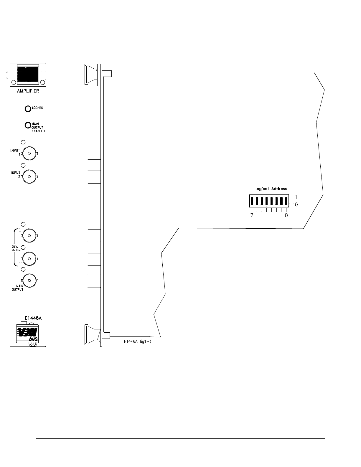
Device Information
Device type: register-based
C-size (1 slot)
Addressing modes: A16
VXIbus Revision Compliance: 1.3
SCPI Revision: 1991.0
See side of module for power/cooling
requirements
Figure 1-1. The E1446A Summing Amplifier/DAC.
1-2 Getting Started General Description
Page 12

Preparation for Use
This section shows you how to configure th e m odule, install it in the
Agilent 75000 Seri e s C mai n frame, address the modul e , and download the
SCPI dr iver.
Note The followin g VXIbu s conf iguration information pertains to the
Agilent E1446A S umm ing Amplifier/DAC. For more (VXIbu s) system
configurat ion information, refer to the C-Size VXIbus Syst em s "I nstallation
and Getting Started Guide" (Agilent P/N E14 05-90021).
Confi g u r in g th e
Amplifier
The Agilent E1446 A Summ ing Amplifier/DAC can be conf i gur e d as a
servant of the Agile nt E1445A Arbitrary Functi on Gene rat or or as a
stand-alone Power Amplifier/DAC.
Logical Add res s The Agilent E1446A logical address is used as foll ows :
• to
place the amplifier in the servant area of a commander such as the
Agilent E1445A AFG, Agilent E1405 Command Module, or an
embedded controller.
In Agilent V XI bus systems, the se r va nt a r ea is defined as:
Servant area = (lo gic a l a ddr ess + 1) through (logical a ddr e ss
+ servant area switch setting)
For example, to place the amplifier in the servant area of the
Agilent E1445A:
Agilent E1445A Logical address: 80
Agilent E1445A Servant Area setting: 8
Agilent E1446A Logical address: 88
Servant Area = (80 + 1) through (80 + 8)
• to address the Agilen t E1446A (see "Addressi ng the Amplifier" later
in this c hapter).
The logical addr e ss factory setting is 88. You c an change the setting during
module inst al la t ion. Valid addresses are from 1 to 255. The amplifier’s
logical addre ss switch is shown in Figure 1- 2.
Note The Agilent E1446A c a n be set to a ny va l id logical address (1 - 255).
However, when used with t he Agilent E1445A or Agilent E1405/06, the
Preparati on for Use Getting Start ed 1-3
Page 13

(Agilent E1446A) logical address or the ( Agilent E1445A/E14 05/ 06)
servant area must be set such that the Agilent E1446A is in the servant area
of its intend ed commander.
Figure 1-2. Setting the E1446A Logical Address.
Install in g the
Amplifier
The Agilent E1446A Amplifier/DAC can be installed in any ma inf ra me slot,
except slot 0. I f the Agil en t E1445A AFG is a part of your system , i t is
recommended that the Amplifier/DAC be installe d in a slot adjacent to the
AFG. Figure 1-3 shows how to install the modul e in th e Agi lent E1400
Series C mainframe.
1-4 Getting Started Preparation for Use
Page 14
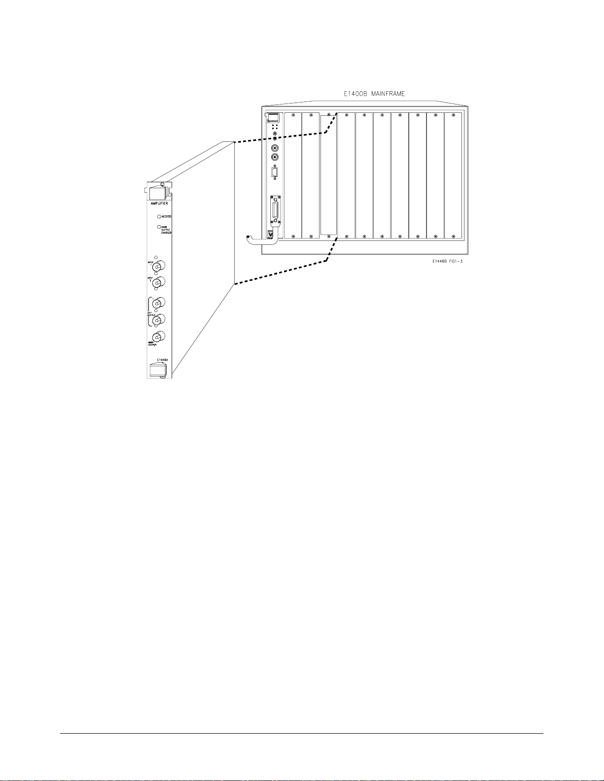
Figure 1-3. Installing the E1446A Summing Amplifier/DAC.
Addressing the
Amplifier
Using an External
Controller
The Agilent E1446A Sum mi ng Amp li fie r/DAC ca n be add ressed by an
external cont ro ll e r or by an embe dded controller. Thi s sec tion describes
how to address the a mpl if ier using an external c ontroller with the
Agilent E1445 A AFG, with the Agil e nt E1405/06 Command Module, and
with an embedded c ontroller.
The Agilent E1446A can be programmed from an external controller via the
Agilent E1445 A AFG or the Agil e nt E1405/06 Command Module. In an
Agilent VXIbus system using an external controller, the amplifier is located
by an (GPIB) address which consists of an interface select code, a primary
GPIB address, and a seconda ry GPIB addr ess:
Interface Select Code: Det e rm ined by the address of the GPIB interface
card in the controller. For most Agilent Technologies controllers, this card
has a factory set address of 7.
Primary GPIB Address: Determined by the a ddr e ss of the GPIB por t on
the Agilent E1405 Command Module. Valid addresses for the Com mand
Module are 0 to 30. The Command Module has a factory set address of 9.
Preparati on for Use Getting Start ed 1-5
Page 15

Secondary GPIB Address : Determined by dividing the logical address of
the device by 8. If the am plifier is used with the Agilent E1445A, th e
secondary addr ess is the E1445A logica l add r es s/8. If the amplifie r is used
with the Agilent E1405/06 Command Module, the secon da ry add ress is the
E1446A logica l ad dre ss/8.
Agilent E1445A AFG
An example of the GPIB address in an BASIC statement when the amplifier
is a servant of the Agilent E1445A is:
OUTPUT 70910;"SOUR2:VOLT:OFFS 3"
Where:
Interface Select Code = 7
(Command Modul e) Prima ry GPIB Address = 09
Secondary GPIB address (Agile nt E1445A logical addr e ss/ 8) = 10
Agilent E1405/06 Command Module
An example of the GPIB address in an BASIC statement when the amplifier
is a servant of the Agilent E1405/06 is:
OUTPUT 70911;"SOUR:VOLT:OFFS 3"
Where:
Interface Select Code = 7
(Command Modul e) Prima ry GPIB Address = 09
Secondary GPIB address (Agile nt E1446A logical addr e ss/ 8) = 11
Refer to Chapte r 2, "P r ogr amming the Agilent E1446A", for more detailed
information.
1-6 Getting Started Preparation for Use
Page 16

Using an Embedded
Controller
The Agilent E1446A Sum mi ng Amp li fie r/DAC ca n be progr ammed a cro ss
the VXIbus backplane (select code 16) from an embedded controller, such
as the Agilent E1480A V/360. With this con figur a ti on, c omm unication with
the registe r -b as ed am pli f ie r module can be accomplished via four pat hs:
1. Embedded controller across the VXIbus bac kplane to the
Agilent E1445A AFG (SCPI programming only).
2. Embedded c ont ro ller to the Agilent E1 405/06 Command Mod ule via
the GPIB interface (SCPI or register-based).
3. Embedded controller to the Agil e nt E1405/06 over the GPIB an d via
the Agilent E1445A (SCPI only).
4. Embedded controller across the VXIbus bac kplane to the
Agilent E1446A (register-based programming only).
Examples of how t he amplifier is addressed in paths 1 through 3 are given
below. Refer to Appendix C for informati on on a ddr e ssing the amplifie r
during registe r-base d programming.
OUTPUT 1680;"INP:IMP 75"
1.
Downloading the
Agilent E1446A
SCPI Driver
In this addressing configuratio n, the E1445A must be in the servant area of
the embedded controller, and the E1446A must be in the servant area of the
E1445A. Select c ode 16 is the only select code that can be used with this
configuration.
OUTPUT 70911;"INP:IMP 75"
2.
In this addressing configuratio n, the E1446 must be in the serva nt are a of
the E1405/06. Select code 7 (GPIB) is the onl y se le c t code that can be used
with this conf i gur a ti on.
OUTPUT 70910;"INP:IMP 75"
3.
In this config ur ation, the E1445 mus t be in the servant area of the E 1405/06.
The E1446 must be in the servant area of the E1445A. Select code 7 (GPIB)
is the only sele c t c ode tha t can be use d with this configur a ti on.
When using the Agil en t E1445A AFG, the SCPI driver is reside nt in ROM
and ready to contro l the Agilent E1446A. However, to use the Agilent
E1405 Comman d Module, the SCPI driver must be downloaded into the
Command Modu le ’ s non- volatile mem or y from a di sk. Both DOS and LIF
formatted driver disks are shipped with t he Agil en t E1446A. The drivers
can be downloaded from con trol le rs ru nning DOS, BASIC (workstation) ,
Preparati on for Use Getting Start ed 1-7
Page 17

IBASIC, or B ASI C/UX. Downloadable driver ca pa bility is ava ilable on the
Agilent E1406 and on the E1405 with firmware revision A.06. 00 or later.
To verify the firmwa re r ev isi on of the Command Module, you c an use the
*IDN? Command:
10 DIM A$[40]
20 OUTPUT 70900;"*IDN?"
30 ENTER 70900;A$
40 PRINT A$
50 END
*IDN? returns identification information for the Agilent E1405 Command
Module. The result of this comma nd i s:
HEWLETT-PACKARD,E1405B,0,A.06.00
Note For information on how to download the SCPI driver, re fer to the
"Downloading Device Drivers Installation Note" (Agilent P/N
E1400-90021), or the "Agilent E1405B Com ma nd Module User’s Manual"
(Agilent P/N E1405-90004).
Basic Operation
This section provides a block diagram an d de sc ription of the basic operat io n
of the Agilent E1446A Summing Amplifier/DAC. The de sc ript ion is
divi ded into three parts :
• Input
• Output
• Offset DAC
Additional ly, the Output section is subdivided into two parts:
• Main Output
• Differential (small signal) Output.
Refer to Appendix A, "Agilent E1446A Specifica ti ons", for operating
specifications.
1-8 Getting Started Basic Operation
Page 18
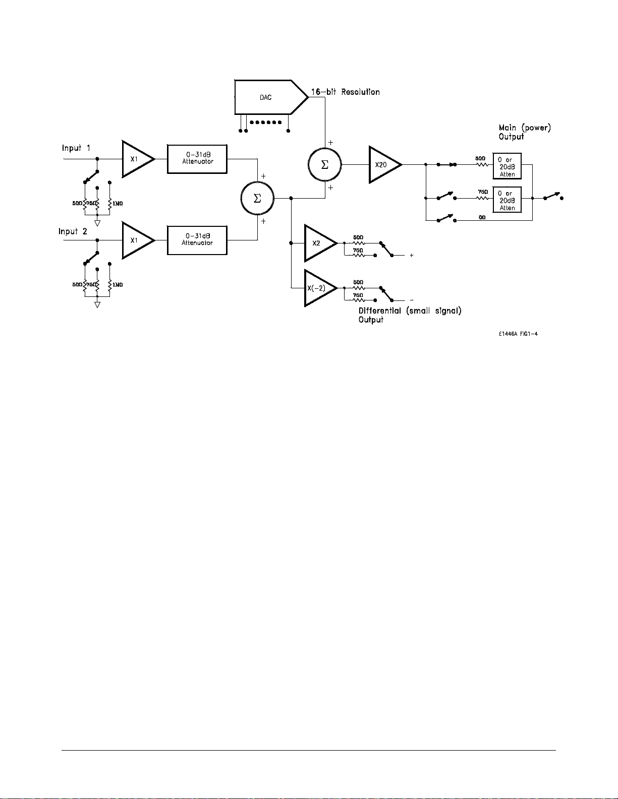
Figure 1-4. E1446A Summing Amplifier/DAC Block Diagram.
Amplifier Block
Diagram
Input The Agilent E1446A Summing Amplifier/DAC has two inp ut cha nne ls that
Output The output channels provide the amplifier with the capabilit y to boost the
Main Output The power amplifier sums the two input channels plus the output of a 16-bit
Figure 1-4 shows a bloc k dia gr a m of the Agilent E1446A Summi ng
Amplifier/DAC.
have identica l input amplifier s wit h independently c ont r olled input
impedance and input attenuation. The input amplifier attenuators provide
independent level control prior to the summing no de . The a tt en ua ti on c an
range from 0 to 31 dB in 1 dB steps. The input impedance can be set to
50Ω, 75Ω, or 1 MΩ.
power output of a low-powe r signal source, and to provide low- l ev el
differential output. The output channels are:
• single-ended main output or power amplifier.
• differential (small signal) output; one inverting, one non- inverting.
offset Digital- to- Ana log Converter (DAC) to obtai n out put levels of ±10
Vpeak into a 50Ω or 75
into high i mpeda nc e . T he voltage gain of the power am pl if ie r is se t at 10
(20 dB) into a matched load, and at 20 ( ab out 26 dB) into a high impedance.
To obtain the desired output, the output attenuation and the output
impedance can be independently sele c te d. The output impedance can be se t
Ω load on the si ngle-ended output or ±20 Vpeak
Basic Operation Getting Started 1-9
Page 19

to 50Ω or 75Ω, or to 0Ω for driving into high impe da nc e . The output
voltage can be att e nua te d by either 0 or 20 dB when 50Ω or 75Ω output
impedance is selected. Output attenuation is unavailable with the 0Ω mode
(high impe da nc e).
The main output terminal may be en ab le d or disabled under user co ntr ol.
When disable d, the output appears as an open c ir c uit . This output is also
overload protec te d vi a an output relay. The output relay automati cally opens
when an overload condition is detecte d a nd disconnects the out put from the
load. An overlo ad occur s i f t he sum of the inputs, plu s the output of the
offset DAC, is excessive, or if the output current limit is reached. The relay
remains ope n unt il the overload cond ition is corrected and the output is rese t
by the user. Refer to Appe ndi x A o f this manual for these spec ifications.
Differential (Small
Signal) Output
The differential (small signa l) output sums the two input channels to obt ai n
a maximum output level of ±1 Vpeak into a 50/75Ω load. One of the
outputs is a non -i nver ti ng a mplifier (same pola rity as the input); where as the
other is an inverti ng a mp lifier (opposite polarity as the input). Into a high
impedance, ea ch input has a maximum gai n of two. The out put impedance
of each amplifi er c an be i nde pe nde nt ly set to either 50Ω or 75Ω.
With two low le ve l ou tput terminals, ou tput signals can be take n f r om e ither
of the termina ls with respect to ground , or across the two termin als ( in
series). Output signals take n ac ro ss the two terminals will result in two
times the input voltage. Fi gure 1 -5 shows the circuitry of th e output signal
taken across the two termina ls.
Figure 1-5. Measuring the Differential Output across both Terminals.
1-10 Getting Started Basic Operation
Page 20

Offset DAC A precision (DAC) allows the Agilent E1446A to provide DC offset
voltage levels. The DAC input is a complementary offset bi na r y co de . Th e
full scale output provides approximately ±10V into 50Ω or 75Ω load, or
approximately ±20V into hig h impedance .
Basic Operation Getting Started 1-11
Page 21

1-12 Getting Started Basic Operation
Page 22

Programming th e Agilen t E1446A
Chapter Contents
This chapter shows you how to program the Agilent E1446A using SCPI
Commands. The prog r amming exampl es found in the chapter ar e
written in BASIC. The main sections of the chapter are:
• Instrument and Programming Languages . . . . . . . . . . . . 2-1
• Introductory Programs. . . . . . . . . . . . . . . . . . . . . . . . . . . . . 2-5
• Example Programs . . . . . . . . . . . . . . . . . . . . . . . . . . . . . . . . 2-8
• Generating and Amplifying Sine Waves . . . . . . . . . . . . . . 2-9
• Setting the Input Impeda nce. . . . . . . . . . . . . . . . . . . . . . . . 2-14
• Setting DC Voltage Offsets. . . . . . . . . . . . . . . . . . . . . . . . . 2-20
• Using the Differential (small signal) Outputs. . . . . . . . . . 2-26
• Summing Two Signals. . . . . . . . . . . . . . . . . . . . . . . . . . . . . . 2-31
Instrument and Programming Languages
Chapter 2
Thoug h the E1446A amplifier is a register-based device, this module can
be programmed with SCPI commands using the Agilent E1445A AFG
or Agilent E1405 Command Module. This section describes the SCPI
programmi ng environm ent.
SCPI Programming SCPI (Standard Commands for Programmable Instruments) i s an
ASC I I -based instrument command language des igned for test and
measurement instruments. The Agilent E1445A AFG or the Agilent
E1405 Command Module (wi th the amplifier driver installed) interprets
the ASCII c ommand strings and s ets the amplifier accordingly. The
AFG and Command Module do this by writing to the amplifier registers.
SCPI Command
Structure
The Agilent E1446A SCPI command set is found in Cha pter 3. SCPI
comma nds a r e b a sed on a hierarchical structure, also known as a tr ee
s ys tem. In this system, ass ociated commands are grouped together under
a c ommon nod e or r oot, thus, form ing subtrees or subsystems . An
exam ple is the amplifier’s ’OUTPut2’ subsystem shown on the fol lowing
page:
Instrument and Program ming Languages Programming the Agilent E1446A 2-1
Page 23

OUTPut2
:ATTenuati on <attenuation>
:IMP edance <impedance>
:OV E R load? [que ry only]
[:STATe] < mode>
:ACTual? [query only]
OUTPut2 is the root ke ywor d of the c ommand, :ATTenua ti on, :I MP ed an ce,
:OVERload?, and [ :ST ATe ] are se co nd leve l keywords, and :ACTua l? is the
third level key wor d. A col on (:) alwa ys se pa rat e s a com ma nd keyword from
a lower level keyword as shown below:
OUTP2:STAT:ACT?
A semicolon (;) is used to sep ar a te two or more comma nds within the sam e
subsystem, an d can a lso save typing. For exa mple, sending thi s c ommand
message:
OUTP2:IMP 50;OUTP2:ATT 6;OUTP2:STAT ON
is the same as sen d ing these three commands:
OUTP2:IMP 50
OUTP2:A TT 6
OUTP2:STAT ON
A semicolon (;) and a col o n (:) are used to separate t w o or mor e comm ands
from different subsystems in the same command message. For example:
INP1:IMP 50;:OUTP2:IMP 50
Command Coupli ng The followi ng a mpl if i er c ommands are value cou ple d:
E1446 with E1405/06
OUTPut1:ATTenuation <attenuation>
OUTPut1:IMPedance <impedance>
SOURce:VOLTage[:LEVel][:IMMediate]:OFFSet <voltage>
E1446 with E1445
OUTPut2:ATTenuation <attenuation>
OUTPut2:IMPedance <impedance>
SOURce2:VOLTage[:LEVel][:IMMediate]:OFFSet <voltage>
This means th at se nding one of these comm a nds c a n ch an ge the va lue se t
previousl y by an other one of these commands. Often, thi s r es ults in
“Settings Conflict” errors when the program executes. To prevent these
errors these com ma nds must be execute d in a "c oupling group".
2-2 Programming the Agilent E1446A Instrument and Programming Languages
Page 24

Executing Coupled
Commands
The list b el ow identifies ru le s to follow when exe c uting coupled commands:
• Coupled commands must be con tiguous and execute d in the same
program stateme nt. This done by pl aci ng the commands in th e same
program line, or b y suppressing the end- of-l ine terminator until the
last c ou pled c omman d has be e n sent.
To send multi ple c ommands in a single lin e or in a single statemen t ,
the commands are linked (as described previously) with a semicolon
(;) and a colon(:). For example:
OUTP2:IMP 50;OUTP2:ATT 6
or
OUTP2:IMP 50;
:OUTP2:ATT 6
In BASIC programs, the end-of-line (EOL) term inator is suppressed
by placing a semicolon (;) following the quotation ma r k (") whic h
closes the command string. For example:
OUTPUT 70910;"OUTP2:IMP 50;";
OUTPUT 70910;":OUTP2:ATT 6"
OUTPUT 70910;"OUTP2:STAT ON"
As shown, the fir st two lines are coupl ed toge ther. The third li ne is
not a coupled command, therefore, the EOL terminator is not
suppressed on the second line.
• Commands not in th e coupling group must either preceed or foll ow
commands in the c oupling group.
• Un-coupled commands ex ecut e d in a co upl ing group break the
coupling.
• Error checking occurs at the en d of the co upl ing group.
• Hardware updates occur at the e nd of the c oupling group.
Instrument and Programming Languages Programming the Agilent E1446A 2-3
Page 25

Instrument Driver
and Example
Programs Disks
The E1446A instrument driver and the example programs contained in this
manual are loc a ted on the following disks:
• Agilent E1446A Instrument Driver and BASI C Examp le
Programs - 3.5" 720 kbyte dis k LIF For mat (E1446-10031)
• Agilent E1446A Instrument Driver and BASI C Examp le
Programs - 3.5" 1.44 M byte disk DO S Form at ( E14 46- 10032)
The example programs are SCPI programs written in BASIC. On the LIF
formatted disk (E1446-10031 ), th e program s are in LOAD / STORE
(PROG) format. On the DOS formatted disk (E1446-10032), the progra ms
are in GET / SAVE (ASCII) format.
System
Configuration
Each program in thi s ch ap te r is written in BASIC. Except whe re noted, the
programs were develope d on t he following system:
Controller: HP 9000 Series 300
Mainframe: Agilen t 75000 Se r ies C
Slot 0/Resource Manager: Agilent E1405B Command
Module
E1445A Logical Address: 80
E1445A Se r va n t Area: 8
E1446A Logical Address: 88
Instrument Language: SCPI
2-4 Programming the Agilent E1446A Instrument and Programming Languages
Page 26

Introductory Programs
The introdu ct ory pr ogr a ms in this section inc lud e:
• Executing the Ag ilent E1446A self - te st.
• Resetting the Agile nt E 1446A and clearing the Error Queue.
• Querying the Agilent E1 446A power-on/reset sett ings.
The introdu ctor y pr ogra m e xa mp le s in this section were writt e n with the
Agilent E1405 Com ma nd Module as the commande r of the Agilent E1446A
Summing Amplifier/DAC.
Executing the
Self-Test
Executing the Self-Test
1 !Agilent E1446A Self-test
10 !Send the self-test command, enter and display the result.
20 OUTPUT 70911;"*TST?"
30 ENTER 70911;Rslt
40 PRINT Rslt
50 END
The amplifier self-test is executed with the command:
*TST?
During the self-test, communication between the command module and the
on-card registers is tested. The *TST? returns one of the self-test codes
listed below:
• 0 = passed.
• 1 = failed. (An error message describes the failure.)
Introductor y Progra ms Programm ing the Ag il ent E1446A 2-5
Page 27

Resetting and
The commands to reset and clear the amplifier are:
Clearing the Agile n t
E1446A
Resetting and Clearing the Agilent E1446A
1 !Resetting and clearing the Agilent E1446A
10 !Assign an I/O Path for the computer, command module, and the
20 !E1446A. Send the appropriate commands and wait for completion.
30 ASSIGN @Amp to 70911
40 OUTPUT @Amp;"*RST;*CLS;*OPC?"
50 ENTER @Amp;Complete
60 END
*RST
*CLS
Resetting the amplifier set s it to its power-on config ur at ion. Clearing status
on the amplifier clears the error queue.
Querying the
Power-on/Reset
Configuration
The command used t o que r y each Agilent E1446A setting i s:
*LRN?
The *LRN? command queries the power-on/reset configuration and returns
a sequence of commands that may be re-sent to the amplifier.
2-6 Programming the Agi lent E1 446A Introductory Pr ogr am s
Page 28

LRN
1 !RE-STORE "LRN"
10 !Assign an I/O path between the computer and the amplifier.
20 ASSIGN @Amp TO 70911
30 !Call the subprogram
40 Lrn_conf(@Amp)
50 END
60 !
70 SUB Lrn_conf(@Amp)
80 Lrn_conf: !subprogram which queries the amp reset configuration
90 DIM Lrn$[1000]
100 OUTPUT @Amp;"*LRN?"
110 ENTER @Amp;Lrn$
120 Lrn$=Lrn$&";"
130 REPEAT
140 I=POS(Lrn$,";")
150 PRINT Lrn$[1;I-1]
160 Lrn$=Lrn$[I+1]
170 UNTIL Lrn$=""
180 SUBEND
Table 2-1. E1446A Power-On/Reset Configuration (as returned by *LRN?).
Parameter Command
Agilent E1446A Agilent E1445A
Input1 Attenuation INP1:ATT INP1:ATT +0.00000000E+000 0 dB
Input1 Impedance INP1:IMP INP1:IMP +5.00000000E+001
Input2 Attenuation INP2:ATT INP2:ATT +0.00000000E+0000 0 dB
Input2 Impedance INP2:IMP INP2:IMP +5.00000000E+001
Main Output Attenuation OUTP1:ATT OUTP2:ATT +0.00000000E+000 0 dB
Main Output Impedance OUTP1:IMP OUTP2:IMP +5.00000000E+001
Main Output State OUTP1:STAT OUTP2:STAT 1 (on)
Diff "+" Impedance OUTP2:IMP OUTP3:IMP +5.00000000E+001
Diff "-" Impedance OUTP3:IMP OUTP4:IMP +5.00000000E+001
DC offset SOUR:VOLT:LEV:IMM:OFFS SOUR2:VOLT:LEV:IMM: OFFS +0.00000000E +000 0V
Power-on/Reset
Settings
50Ω
50Ω
50Ω
50Ω
50Ω
Introductor y Progra ms Programm ing the Ag il ent E1446A 2-7
Page 29
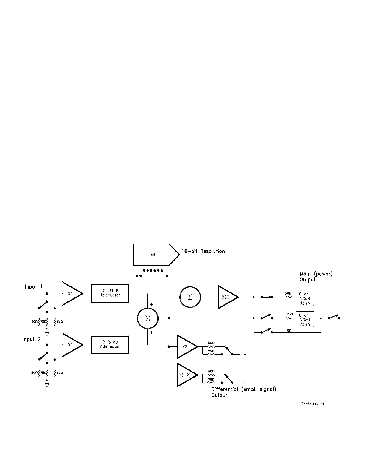
Example Programs
The example programs in this section include:
These programs con figur e the amplifier according t o the block diagram of
Figure 2-1. The prog ram de sc riptions will often re fer to this figure. The
programs were written with the amplifier configured as a servant of the
Agilent E1445A AFG, and as a servant of the Agilent E1405 Command
Module.
Refer to Chapt e r 3, "C ommand Reference" for a detailed des cription of the
Agilent E1446 A comma nds. Refer to Chapter 8 of the "Agilent E14 45A
Arbitrary Function Generators User’s Manual" for a detai led descri p tion of
the Agilent E1445A commands.
• Generating and amplifying sine waves
• Selecting the inpu t impedance
• Using the differen ti al (s ma ll signal) outputs
• Setting a DC offset voltag e
• Summing two signa ls
Figure 2-6. E1446A Functional Block Diagram.
2-8 Programming the Agi lent E1 446A Example Progr am s
Page 30

Generating and Amplifying Sine Waves
The examples in this section show you how to amplify a sine wave
generated by th e Agile nt E1445A. In the first program, the E1446A is a
servant of the E14 45A AFG. I n the se c ond pr ogram, the E1446A ampli f ie s
the signal from the E1445A, however; the E1446A is in the servant area of
the E1405 Command Module.
Amplifying Sine
Waves (A g il en t
E1445A
Commander)
This program uses the E1446A to amplify a 2 Vpp E1445A AFG sign al to
14.15 Vpp. Since the intended output amplitud e and t he input amplitude are
known, the amount of attenuatio n (0 - 31 dB at te nuator) is determine d as:
attenuation
where V
and Vi units (Vpp, Vp) must be the sa me ) . Th us,
attenuation
The (main) output of the AFG is connected to ’Input 1’ of the amplif ie r.
The steps of this program are:
1. Reset the E1445A AFG and E1446A amplifier.
*RST
= 20 LOG (Vo/(Vi * 10))
(dB)
is the output amplitude and Vi is the input signal amplitude (V
o
= 20 LOG (14/20) = -3 dB
(dB)
o
2. Set the AFG frequency, function, and amplitude.
[SOURce:]FREQuency[1][:CW|: FIXed] <frequency>
[SOURce:]FUNCtion[:SHAPe] <shape>
[SOURce:]VOLTage[:LEVel][:IMMediate][:AMPLitude]
<amplitude>
3. Couple the AFG output load value to the output impeda nce valu e .
OUTPut[1]:LOAD:AUTO <mode>
OUTPut[1]:IMP edan ce <impedance>
Generating and Ampl ifyin g Sine W aves Programm ing the Ag ilent E1 446A 2-9
Page 31

4. Set the amplifier in put impedance to mat ch the AFG output loa d.
INPut[1]:I M Pedan ce <impedance>
5. Set the ampl ifier inpu t at t enuation .
INPut[1]:ATT enua tion <attenuation>
6. Set the amplifier output impedance.
OUTPut2:IMPed ance <impedance>
7. Set the amplifier out put atten uation.
OUTPut2 :AT Tenuation <attenuation>
8. Place the AFG in the wait-for-arm state.
INITiate:IMMediate
Note Resetting the a mplifier sets many of the sa me c onditions set by sub se que nt
(amplifier) commands in the program. These commands are included,
however, to show othe r part s of the am plifier configuration.
AMPL45
Note For more informati on on how to program the Agilent E1445A AFG, refer to
the Agilent E1445A Arbritrary Func tion Generator User’s Manual.
1 !RE-STORE"AMPL45"
2 !The following program uses the E1445A to generate a 1 kHz, 2Vpp
3 !sine wave. The Agilent E1446A amplifies the signal to approximately 14 Vpp.
4 !
10 !Assign I/O path between the computer and E1445A. As the commander of
20 !the Agilent E1446A, the E1445A sends the amplifier its commands.
30 ASSIGN @Afg TO 70910
40 COM @Afg
50 !
60 !Set up error checking
70 ON INTR 7 CALL Errmsg
80 ENABLE INTR 7;2
Continued on Next Page
2-10 Programming the Agilent E1446A Generating and Amplifying Sine Waves
Page 32

90 OUTPUT @Afg;"*CLS"
100 OUTPUT @Afg;"*SRE 32"
110 OUTPUT @Afg;" *ESE 60"
120 !
130 !Call the subprograms
140 Rst
150 Sine_wave
160 !
170 WAIT .1 !allow interrupt to be serviced
180 OFF INTR 7
190 END
200 !
210 SUB Sine_wave
220 Sine_wave: !Subprogram which sets the E1445A to output a sine wave
230 COM @Afg
240 OUTPUT @Afg;"SOUR:FREQ1:FIX 1E3;"; !frequency
250 OUTPUT @Afg;":SOUR:FUNC:SHAP SIN;"; !function
260 OUTPUT @Afg;":SOUR:VOLT:LEV:IMM:AMPL 2VPP;"; !amplitude
270 OUTPUT @Afg;":OUTP:LOAD:AUTO ON;"; !couple load to impedance
280 OUTPUT @Afg;":OUTP:IMP 50" !output impedance
290 !
300 !Set up the Agilent E1446A
310 OUTPUT @Afg;"INP1:IMP 50" !input impedance
320 OUTPUT @Afg;"INP1:ATT 3" !input attenuation (dB)
330 OUTPUT @Afg;"OUTP2:IMP 50;"; !main output impedance
340 OUTPUT @Afg;":OUTP2:ATT 0" !main output attenuation
350 !
360 OUTPUT @Afg;"INIT:IMM" !E1445A wait-for-arm state
370 SUBEND
380 !
390 SUB Rst
400 Rst: !Subprogram which resets the E1445A and E1446A
410 COM @Afg
420 OUTPUT @Afg;"*RST;*OPC?" !reset the AFG
430 ENTER @Afg;Complete
440 SUBEND
450 !
460 SUB Errmsg
470 Errmsg: !Subprogram which displays E1445/E1446 programming errors
480 COM @Afg
490 DIM Message$[256]
500 !Read AFG status byte register and clear service request bit
510 B=SPOLL(@Afg)
520 !End of statement if error occurs among coupled commands
530 OUTPUT @Afg;""
540 OUTPUT @Afg;"ABORT" !abort output waveform
Continued on Next Page
Generating and Amplifying Sine Waves Programming the Agilent E1446A 2-11
Page 33

550 REPEAT
560 OUTPUT @Afg;"SYST:ERR?" !read AFG error queue
570 ENTER @Afg;Code,Message$
580 PRINT Code, Message$
590 UNTIL Code=0
600 STOP
610 SUBEND
Amplifying Sine
Waves (A g il en t
E1405 Commander)
AMPL05
1 !RE-STORE"AMPL05"
2 !The following program uses the Agilent E1445A to generate a 1 kHz, 2Vpp
3 !sine wave. The Agilent E1446A amplifies the signal to approximately 14 Vpp.
4 !
10 !Assign I/O paths between the computer and E1445A, and between the
20 !computer and E1405. As the commander of the E1446A, the E1405 sends the
30 !amplifier its commands.
40 ASSIGN @Afg TO 70910
50 ASSIGN @Amp TO 70911
60 COM @Afg,@Amp
70 !
80 !Set up error checking
90 ON INTR 7 CALL Errmsg
100 ENABLE INTR 7;2
110 OUTPUT @Afg;"*CLS"
120 OUTPUT @Afg;"*SRE 32"
130 OUTPUT @Afg;" *ESE 60"
140 !
This program us es the sa me co mmands and sequence as previously
described, exc ep t for the OUTPu t[ 1] co mm an ds shown below:
6. Set t he amplifiero ut put impedance.
OUTPut[1]:IMP edan ce <impedance>
7. Set the amplifier outpu t atte nuat ion .
OUTPut[1]:ATTenuation <attenuation>
In this example , the E1446A is a servant to the E1405. As such, commands
sent to the amp li fi e r (at se c onda ry GPIB add ress 11 ) are parsed by the
Command Modu le rather than by the E1445A.
Continued on Next Page
2-12 Programming the Agilent E1446A Generating and Amplifying Sine Waves
Page 34

150 OUTPUT @Amp;"*CLS"
160 OUTPUT @Amp;"*SRE 32"
170 OUTPUT @Amp ;"*ESE 60"
180 !
190 !Call the subprograms
200 Rst
210 Sine_wave
220 !
230 WAIT .1 !allow interrupt to be serviced
240 OFF INTR 7
250 END
260 !
270 SUB Sine_wave
280 Sine_wave: !Subprogram which sets the E1445A to output a sine wave
290 COM @Afg,@Amp
300 OUTPUT @Afg;"SOUR:FREQ1:FIX 1E3;"; !frequency
310 OUTPUT @Afg;":SOUR:FUNC:SHAP SIN;"; !function
320 OUTPUT @Afg;":SOUR:VOLT:LEV:IMM:AMPL 2VPP;"; !amplitude
330 OUTPUT @Afg;":OUTP:LOAD:AUTO ON;"; !couple load to impedance
340 OUTPUT @Afg;":OUTP:IMP 50" !output impedance
350 !
360 !Set up the Agilent E1446A
370 OUTPUT @Amp;"INP1:IMP 50" !input impedance
380 OUTPUT @Amp;"INP1:ATT 3" !input attenuation (dB)
390 OUTPUT @Amp;"OUTP1:IMP 50;"; !main output impedance
400 OUTPUT @Amp;":OUTP1:ATT 0" !main output attenuation
410 !
420 OUTPUT @Afg;"INIT:IMM" !E1445A wait-for-arm state
430 SUBEND
440 !
450 SUB Rst
460 Rst: !Subprogram which resets the E1445A and E1446A
470 COM @Afg,@Amp
480 OUTPUT @Afg;"*RST;*OPC?" !reset the AFG
490 ENTER @Afg;Complete
500 OUTPUT @Amp;"*RST;*OPC?" !reset the AMP
510 ENTER @Amp;Complete
520 SUBEND
530 !
540 SUB Errmsg
550 Errmsg: !Subprogram which displays E1445/E1446 programming errors
560 COM @Afg,@Amp
570 DIM Message$[256]
580 !Read AFG (at sec addr 10) status byte register, clear service
590 !request bit
600 B=SPOLL(@Afg)
Continued on Next Page
Generating and Amplifying Sine Waves Programming the Agilent E1446A 2-13
Page 35

610 IF BIT(B,6) THEN !AFG requested service
620 !End of statement if error occurs among coupled commands
630 OUTPUT @Afg;""
640 OUTPUT @Afg;"ABORT" !abort output waveform
650 PRINT "E1445A errors"
660 PRINT
670 REPEAT
680 OUTPUT @Afg;"SYST:ERR?" !read AFG error queue
690 ENTER @Afg;Code,Message$
700 PRINT Code,Message$
710 UNTIL Code=0
720 STOP
730 END IF
740 !
750 !Read AMP (at sec addr 11) status byte register, clear service
760 !request bit
770 B=SPOLL(@Amp)
780 IF BIT(B,6) THEN !amplifier requested service
790 !End of statement if error occurs among coupled commands
800 OUTPUT @Amp;""
810 PRINT "E1446A errors"
820 PRINT
830 REPEAT
840 OUTPUT @Amp;"SYST:ERR?"!read AMP error queue
850 ENTER @Amp;Code,Message$
860 PRINT Code,Message$
870 UNTIL Code=0
880 END IF
890 STOP
900 SUBEND
Setting the Input Impedance
The examples in this section show you how to amplify a sine wave
generated by th e Agile nt E1445A. In the first program, the E1446A is a
servant of the E14 45A AFG. I n the se c ond pr ogram, the E1446A ampli f ie s
the signal from the E1445A, however; the E1446A is in the servant area of
the E1405 Command Module.
Setting the Input
Impedance
(Agilent E1445A
Commander)
2-14 Programming the Agilent E1446A Setting the Input Impedance
This program set s the E1446A’s input imp ed an ce to match the outpu t
impedance of the E1445A. The signal supplie d by the E1445A is a 1 Vpp, 2
MHz square wave. The signal is amplified to 6.3 Vpp. Again, when the
intended ou tput amplitude and the input amplit ude are known, the amount of
attenuation ( 0 - 31 dB attenuator) is determ ine d by:
Page 36

attenuation
= 20 LOG (Vo/(Vi * 10))
(dB)
where V
is the output amplitude and Vi is the input signal amplitude (V
o
and Vi units (Vpp, Vp) must be the sa me ) . Th us,
attenuation
= 20 LOG (6.3/10) = -4 dB
(dB)
Again, the (main) out put of the AFG is connected to ’Input 1’ of th e
amplifier.
The steps of this program are:
1. Reset the E1445A AFG and E1446A amplifier.
*RST
2. Set the AFG frequency, function, and amplitude.
[SOURce:]FREQuency[1][:CW|: FIXed] <frequency>
[SOURce:]FUNCtion[:SHAPe] <shape>
[SOURce:]VOLTage[:LEVel][:IMMediate][:AMPLitude]
<amplitude>
o
3. Set the AFG output loa d and output impedanc e values.
OUTPut[1]:LOAD <load>
OUTPut[1]:IMP edan ce <impedance>
4. Set the amplifier in put impedance to mat ch the AFG output loa d.
INPut[1]:I M Pedan ce <impedance>
5. Set the ampl ifier inpu t at t enuation .
INPut[1]:ATT enua tion <attenuation>
6. Set the amplifier output impedance.
OUTPut2:IMPed ance <impedance>
7. Set the amplifier out put atten uation.
OUTPut2 :AT Tenuation <attenuation>
Setting the Input Impedance Programming the Agilent E1446A 2-15
Page 37

IN_IMP45
8. Place the AFG in the wait-for-arm state.
INITiate:IMMediate
Note Resetting the a mplifier sets many of the sa me c onditions set by sub se que nt
(amplifier) commands in the program. These commands are included,
however, to show othe r part s of the am plifier configuration.
1 !RE-STORE"IN_IMP45"
2 !This program sets the AFG’s output impedance and output load
3 !to 75 ohms. The Agilent E1446A amplifier’s input impedance is set to
4 !75 ohms to match the AFG. The 1 Vpp AFG square wave is amplified
5 !to 6.3 Vpp.
6 !
10 !Assign I/O path between the computer and E1445A.
20 ASSIGN @Afg TO 70910
30 COM @Afg
40 !
50 !Set up error checking
60 ON INTR 7 CALL Errmsg
70 ENABLE INTR 7;2
80 OUTPUT @Afg;"*CLS"
90 OUTPUT @Afg;"*SRE 32"
100 OUTPUT @Afg;" *ESE 60"
110 !
120 !Call the subprograms
130 CALL Rst
140 CALL Out_load
150 !
160 WAIT .1 !allow interrupt to be serviced
170 OFF INTR 7
180 END
190 !
200 SUB Out_load
210 Out_load: !Subprogram which sets the output load
220 COM @Afg
230 OUTPUT @Afg;"SOUR:FREQ1:FIX 2E6;"; !frequency
240 OUTPUT @Afg;":SOUR:FUNC:SHAP SQU;"; !function
250 OUTPUT @Afg;":SOUR:VOLT:LEV:IMM:AMPL 1VPP;"; !amplitude
260 OUTPUT @Afg;":OUTP:IMP 75;"; !output impedance
270 OUTPUT @Afg;":OUTP:LOAD 75" !output load
Continued on Next Page
2-16 Programming the Agilent E1446A Setting the Input Impedance
Page 38

280 !
290 !Set up amplifier
300 OUTPUT @Afg;"INP1:IMP 75" !input impedance
310 OUTPUT @Afg;"INP1:ATT 4" !input attenuation (dB)
320 OUTPUT @Afg;"OUTP2:IMP 50" !main output impedance
330 OUTPUT @Afg;"OUTP2:ATT 0" !main output attenuation (dB)
340 !
350 OUTPUT @Afg;"INIT:IMM" !E1445A wait-for-arm state
360 SUBEND
370 !
380 SUB Rst
390 Rst: !Subprogram which resets the E1445 and E1446
400 COM @Afg
410 OUTPUT @Afg;"*RST;*OPC?" !reset the AFG
420 ENTER @Afg;Complete
430 SUBEND
440 !
450 SUB Errmsg
460 Errmsg: !Subprogram which displays E1445/E1446 programming errors
470 COM @Afg
480 DIM Message$[256]
490 !Read AFG status byte register and clear service request bit
500 B=SPOLL(@Afg)
510 !End of statement if error occurs among coupled commands
520 OUTPUT @Afg;""
530 OUTPUT @Afg;"ABORT" !abort output waveform
540 REPEAT
550 OUTPUT @Afg;"SYST:ERR?" !read AFG error queue
560 ENTER @Afg;Code,Message$
570 PRINT Code,Message$
580 UNTIL Code=0
590 STOP
600 SUBEND
Setting In put
Impedance
(Agilent E1405B
This program us es the sa me co mmands and sequence as previously
described, exc ep t for the OUTPu t[ 1] co mm an ds shown below:
6. Set the amplifier output im peda nce .
Commander)
OUTPut[1]:IMP edan ce <impedance>
7. Set the amplifier outpu t atte nuat ion .
OUTPut[1]:ATTenuation <attenuation>
Setting the Input Impedance Programming the Agilent E1446A 2-17
Page 39

IN_IMP05
In this example , the E1446A is a servant to the E1405. As such, commands
sent to the amp li fi e r (at se c onda ry GPIB add ress 11 ) are parsed by the
Command Modu le rather than by the E1445A.
1 !RE-STORE"IN_IMP05"
2 !This program sets the AFG’s output impedance and output load
3 !to 75 ohms. The Agilent E1446A amplifier’s input impedance is set to
4 !75 ohms to match the AFG. The 1 Vpp AFG square wave is amplified
5 !to 6.3 Vpp.
6 !
10 !Assign I/O paths between the computer and E1445A and E1405.
20 ASSIGN @Afg TO 70910
30 ASSIGN @Amp TO 70911
40 COM @Afg,@Amp
50 !
60 !Set up error checking
70 ON INTR 7 CALL Errmsg
80 ENABLE INTR 7;2
90 OUTPUT @Afg;"*CLS"
100 OUTPUT @Afg;"*SRE 32"
110 OUTPUT @Afg;" *ESE 60"
120 !
130 OUTPUT @Amp;"*CLS"
140 OUTPUT @Amp;"*SRE 32"
150 OUTPUT @Amp ;"*ESE 60"
160 !
170 !Call the subprograms
180 CALL Rst
190 CALL Out_load
200 !
210 WAIT .1 !allow interrupt to be serviced
220 OFF INTR 7
230 END
240 !
250 SUB Out_load
260 Out_load: !Subprogram which sets the output load
270 COM @Afg,@Amp
280 OUTPUT @Afg;"SOUR:FREQ1:FIX 2E6;"; !frequency
290 OUTPUT @Afg;":SOUR:FUNC:SHAP SQU;"; !function
300 OUTPUT @Afg;":SOUR:VOLT:LEV:IMM:AMPL 1VPP;"; !amplitude
310 OUTPUT @Afg;":OUTP:IMP 75;"; !output impedance
320 OUTPUT @Afg;":OUTP:LOAD 75" !output load
330 !
Continued on Next Page
2-18 Programming the Agilent E1446A Setting the Input Impedance
Page 40

340 !Set up amplifier
350 OUTPUT @Amp;"INP1:IMP 75" !input impedance
360 OUTPUT @Amp;"INP1:ATT 4" !input attenuation (dB)
370 OUTPUT @Amp;"OUTP1:IMP 50" !main output impedance
380 OUTPUT @Amp;"OUTP1:ATT 0" !main output attenuation (dB)
390 !
400 OUTPUT @Afg;"INIT:IMM" !E1445A wait-for-arm state
410 SUBEND
420 !
430 SUB Rst
440 Rst: !Subprogram which resets the E1445 and E1446
450 COM @Afg,@Amp
460 OUTPUT @Afg;"*RST;*OPC?" !reset the AFG
470 ENTER @Afg;Complete
480 OUTPUT @Amp;"*RST;*OPC?" !reset the AMP
490 ENTER @Amp;Complete
500 SUBEND
510 !
520 SUB Errmsg
530 Errmsg: !Subprogram which displays E1445/E1446 programming errors
540 COM @Afg,@Amp
550 DIM Message$[256]
560 !Read AFG (at sec addr 10) status byte register, clear service
570 !request bit
580 B=SPOLL(@Afg)
590 IF BIT(B,6) THEN !AFG requested service
600 !End of statement if error occurs among coupled commands
610 OUTPUT @Afg;""
620 OUTPUT @Afg;"ABORT"!abort output waveform
630 PRINT "E1445A errors"
640 PRINT
650 REPEAT
660 OUTPUT @Afg;"SYST:ERR?" !read AFG error queue
670 ENTER @Afg;Code,Message$
680 PRINT Code,Message$
690 UNTIL Code=0
700 STOP
710 END IF
720 !
730 !Read AMP (at sec addr 11) status byte register, clear service
740 !request bit
750 B=SPOLL(@Amp)
760 IF BIT(B,6) THEN !amplifier requested service
770 !End of statement if error occurs among coupled commands
780 OUTPUT @Amp;""
790 PRINT "E1446A errors"
Continued on Next Page
Setting the Input Impedance Programming the Agilent E1446A 2-19
Page 41

800 PRINT
810 REPEAT
820 OUTPUT @Amp;"SYST:ERR?" !read AMP error queue
830 ENTER @Amp;Code,Message$
840 PRINT Code,Message$
850 UNTIL Code=0
860 END IF
870 STOP
880 SUBEND
Setting DC Voltage Offsets
These examples show you how to use the amplifier to add a DC offset to a
signal suppl ie d by the E1445A. In the first ex am pl e, the E1446A is a servant
to the E1445A. In the secon d ex am ple, the E1446A is a servant to the E1405
Command Module.
Setting DC Offsets
(Agilent E1445A
Commander)
This program adds an 8V DC offset to a 0.4 Vpp E1445A signal. To
maintain 0. 4 Vpp a t the output, the si gna l is attenuated by 20 dB at the
amplifier in put (Figure 2-1). The offset supplied by the E1446A DAC is
added to the input signal and is amplified. Into 50W, the 0. 4 Vpp signal is
centered on 8V.
The steps of this program are:
1. Reset the E1445A AFG and E1446A amplifier.
*RST
2. Set the AFG frequency, function, and amplitude.
[SOURce:]FREQuency[1][:CW|: FIXed] <frequency>
[SOURce:]FUNCtion[:SHAPe] <shape>
[SOURce:]VOLTage[:LEVel][:IMMediate][:AMPLitude]
<amplitude>
3. Couple the AFG output load value to the output impeda nce valu e .
OUTPut[1]:LOAD:AUTO <mode>
OUTPut[1]:IMP edan ce <impedance>
4. Set the amplifier in put impedance to mat ch the AFG output loa d.
INPut[1]:I M Pedan ce <impedance>
2-20 Programming the Agilent E1446A Setting DC Voltage Offsets
Page 42

5. Set the ampl ifier inpu t at t enuation .
INPut[1]:ATT enua tion <attenuation>
6. Set the ampl if ier main output impedance.
OUTPut2:IMPed ance <impedance>
7. Set the amplifier ma in o ut put atten uat ion.
OUTPut2 :AT Tenuation <attenuation>
8. Set the DC offset value.
SOURce2:VOLTage[:LEVel][:IMMediate]:OFFSet <offset>
9. Place the AFG in the wait-for-arm state.
INITiate:IMMediate
Note Resetting the a mplifier sets many of the sa me c onditions set by sub se que nt
(amplifier) commands in the program. These commands are included,
however, to show othe r part s of the am plifier configuration.
OFFS45
1 !RE-STORE"OFFS45"
2 !This program uses the E1446A to generate an 8V DC offset for a
3 !0.4 Vpp signal supplied by the E1445A AFG. To accomplish this, the
4 !AFG signal is attenuated by 20 dB at the amplifier input. The amplifier
5 !offset is set to 8V, the output impedance to 50 ohms, and the output
6 !attenuation to 0 dB. Into 50 ohms, the 0.4 Vpp signal is centered on
7 !8 volts.
8 !
10 !Assign I/O path between the computer and E1445A. As the commander of
20 !the Agilent E1446A, the E1445A sends the amplifier its commands.
30 ASSIGN @Afg TO 70910
40 COM @Afg
50 !
Continued on Next Page
Setting DC Voltage Offsets Programming the Agilent E1446A 2-21
Page 43

60 !Set up error checking
70 ON INTR 7 CALL Errmsg
80 ENABLE INTR 7;2
90 OUTPUT @Afg;"*CLS"
100 OUTPUT @Afg;"*SRE 32"
110 OUTPUT @Afg;" *ESE 60"
120 !
130 !Call the subprograms
140 Rst
150 Offset
160 !
170 WAIT .1 !allow interrupt to be serviced
180 OFF INTR 7
190 END
200 !
210 SUB Offset
220 Offset: !Subprogram which sets up the E1445A and E1446A
230 COM @Afg
240 OUTPUT @Afg;"SOUR:FREQ1:FIX 1E3;"; !frequency
250 OUTPUT @Afg;":SOUR:FUNC:SHAP SIN;"; !function
260 OUTPUT @Afg;":SOUR:VOLT:LEV:IMM:AMPL .4VPP;"; !amplitude
270 OUTPUT @Afg;":OUTP:LOAD:AUTO ON;"; !couple load to impedance
280 OUTPUT @Afg;":OUTP:IMP 50" !impedance
290 !
300 !Set up the Agilent E1446A
310 OUTPUT @Afg;"INP1:IMP 50" !input impedance
320 OUTPUT @Afg;"INP1:ATT 20" !input attenuation (dB)
330 OUTPUT @Afg;"OUTP2:IMP 50;"; !main output impedance
340 OUTPUT @Afg;":OUTP2:ATT 0;"; !main output attenuation (dB)
350 OUTPUT @Afg;":SOUR2:VOLT:LEV:IMM:OFFS 8" !DC offset
360 !
370 OUTPUT @Afg;"INIT:IMM" !E1445A wait-for-arm state
380 SUBEND
390 !
400 SUB Rst
410 Rst: !Subprogram which resets the E1445A and E1446A
420 COM @Afg
430 OUTPUT @Afg;"*RST;*OPC?" !reset the AFG
440 ENTER @Afg;Complete
450 SUBEND
460 !
470 SUB Errmsg
480 Errmsg: !Subprogram which displays E1445/E1446 programming errors
490 COM @Afg
500 DIM Message$[256]
Continued on Next Page
2-22 Programming the Agilent E1446A Setting DC Voltage Offsets
Page 44

510 !Read AFG status byte register and clear service request bit
520 B=SPOLL(@Afg)
530 !End of statement if error occurs among coupled commands
540 OUTPUT @Afg;""
550 OUTPUT @Afg;"ABORT" !abort output waveform
560 REPEAT
570 OUTPUT @Afg;"SYST:ERR?" !read AFG error queue
580 ENTER @Afg;Code,Message$
590 PRINT Code,Message$
600 UNTIL Code=0
610 STOP
620 SUBEND
Setting DC Offsets
(Agilent E1405
Commander)
OFFS05
This program us es the sa me co mmands and sequence as previously
described, except for the OUTPu t[ 1] an d SOURCe:VOLTage commands
shown below:
6. Set the amplifier main output impedance.
OUTPut[1]:IMP edan ce <impedance>
7. Set the amplifier main output attenuation.
OUTPut[1]:ATTenuation <attenuation>
8. Set the DC offset value.
SOURce:VOLTage[:LEVel][:IMMediate]:OFFSet <offset>
In this example , the E1446A is a servant to the E1405. As such, commands
sent to the amp li fi e r (at se c onda ry GPIB add ress 11 ) are parsed by the
Command Modu le rather than by the E1445A.
1 !RE-STORE"OFFS05"
2 !This program uses the E1446A to generate an 8V DC offset for a
3 !0.4 Vpp signal supplied by the E1445A AFG. To accomplish this, the
4 !AFG signal is attenuated by 20 dB at the amplifier input. The amplifier
5 !offset is set to 8V, the output impedance to 50 ohms, and the output
6 !attenuation to 0 dB. Into 50 ohms, the 0.4 Vpp signal is centered on
7 !8 volts.
8 !
10 !Assign I/O path between the computer and E1445A and E1446A.
20 ASSIGN @Afg TO 70910
30 ASSIGN @Amp TO 70911
Continued on Next Page
Setting DC Voltage Offsets Programming the Agilent E1446A 2-23
Page 45

40 COM @Afg,@Amp
50 !
60 !Set up error checking
70 ON INTR 7 CALL Errmsg
80 ENABLE INTR 7;2
90 OUTPUT @Afg;"*CLS"
100 OUTPUT @Afg;"*SRE 32"
110 OUTPUT @Afg;" *ESE 60"
120 !
130 OUTPUT @Amp;"*CLS"
140 OUTPUT @Amp;"*SRE 32"
150 OUTPUT @Amp ;"*ESE 60"
160 !
170 !Call the subprograms
180 Rst
190 Offset
200 !
210 WAIT .1 !allow interrupt to be serviced
220 OFF INTR 7
230 END
240 !
250 SUB Offset
260 Offset: !Subprogram which sets up the E1445A and E1446A
270 COM @Afg,@Amp
280 OUTPUT @Afg;"SOUR:FREQ1:FIX 1E3;"; !frequency
290 OUTPUT @Afg;":SOUR:FUNC:SHAP SIN;"; !function
300 OUTPUT @Afg;":SOUR:VOLT:LEV:IMM:AMPL .4VPP;"; !amplitude
310 OUTPUT @Afg;":OUTP:LOAD:AUTO ON;"; !couple load to impedance
320 OUTPUT @Afg;":OUTP:IMP 50" !impedance
330 !
340 !Set up the Agilent E1446A
350 OUTPUT @Amp;"INP1:IMP 50" !input impedance
360 OUTPUT @Amp;"INP1:ATT 20" !input attenuation (dB)
370 OUTPUT @Amp;"OUTP1:IMP 50;"; !main output impedance
380 OUTPUT @Amp;":OUTP1:ATT 0;"; !main output attenuation (dB)
390 OUTPUT @Amp;":SOUR:VOLT:LEV:IMM:OFFS 8" !DC offset
400 !
410 OUTPUT @Afg;"INIT:IMM" !E1445A wait-for-arm state
420 SUBEND
430 !
440 SUB Rst
450 Rst: !Subprogram which resets the E1445A and E1446A
460 COM @Afg,@Amp
470 OUTPUT @Afg;"*RST;*OPC?" !reset the AFG
480 ENTER @Afg;Complete
490 OUTPUT @Amp;"*RST;*OPC?" !reset the AFG
Continued on Next Page
2-24 Programming the Agilent E1446A Setting DC Voltage Offsets
Page 46

500 ENTER @Amp;Complete
510 SUBEND
520 !
530 SUB Errmsg
540 Errmsg: !Subprogram which displays E1445/E1446 programming errors
550 COM @Afg,@Amp
560 DIM Message$[256]
570 !Read AFG (at sec addr 10) status byte register, clear service
580 !request bit
590 B=SPOLL(@Afg)
600 IF BIT(B,6) THEN !AFG requested service
610 !End of statement if error occurs among coupled commands
620 OUTPUT @Afg;""
630 OUTPUT @Afg;"ABORT" !abort output waveform
640 PRINT "E1445A errors"
650 PRINT
660 REPEAT
670 OUTPUT @Afg;"SYST:ERR?" !read AFG error queue
680 ENTER @Afg;Code,Message$
690 PRINT Code,Message$
700 UNTIL Code=0
710 STOP
720 END IF
730 !
740 !Read AMP (at sec addr 11) status byte register, clear service
750 !request bit
760 B=SPOLL(@Amp)
770 IF BIT(B,6) THEN !amplifier requested service
780 !End of statement if error occurs among coupled commands
790 OUTPUT @Amp;""
800 PRINT "E1446A errors"
810 PRINT
820 REPEAT
830 OUTPUT @Amp;"SYST:ERR?"!read AMP error queue
840 ENTER @Amp;Code,Message$
850 PRINT Code,Message$
860 UNTIL Code=0
870 END IF
880 STOP
890 SUBEND
Setting DC Voltage Offsets Programming the Agilent E1446A 2-25
Page 47

Using the Differential (small signal) Outputs
These example s show you how to use the ampl if ie r’ s dif f e rent ia l (small
signal) outputs. Note the followi ng whe n using the outputs:
• the differential (s ma ll signal) outputs are designed fo r
high-frequenc y and low-power sour ce applic ati o ns.
• with no attenuati on, the ma ximum input v olt a g e (sum of In put1 and
Input2) must not ex ceed 2 Vpp ( Figur e 2- 1).
In the first example, the E1446A is a servant to the E1445A. In the second
example, the E1446A is a servant to the E1405 Command Module.
Using the
Differ ential Outputs
(Agilent E1445A
Commander)
Rather than am pl if y the input signal, this program attenua te s the signal
supplied by the E1445A to obtain an out put amplitude of 10 mVpp. The
output can be take n at e it he r the ’Di f f +’ or ’Dif f -’ (inve r ted ) output.
The steps of this program are:
1. Reset the E1445A AFG and E1446A amplifier.
*RST
2. Set the AFG frequency, function, and (minimum) amplitude.
[SOURce:]FREQuency[1][:CW|: FIXed] <frequency>
[SOURce:]FUNCtion[:SHAPe] <shape>
[SOURce:]VOLTage[:LEVel][:IMMediate][:AMPLitude]
<amplitude>
3. Couple the AFG output load value to the output impeda nce valu e .
OUTPut[1]:LOAD:AUTO <mode>
OUTPut[1]:IMP edan ce <impedance>
4. Set the amplifier in put impedance to mat ch the AFG output loa d.
INPut[1]:I M Pedan ce <impedance>
5. Set the ampl ifier inpu t at t enuation .
INPut[1]:ATT enua tion <attenuation>
2-26 Programming the Agilent E1446A Using the Differential (small signal) Outputs
Page 48

DIFF45
6. Set the amplifier ’Diff + ’ and ’Diff -’ outpu t impedance s .
OUTPut3:IMPed ance <impedance>
OUTPut4:IMPed ance <impedance>
7. Place the AFG in the wait-for-arm state.
INITiate:IMMediate
Note Resetting the a mplifier sets many of the sa me c onditions set by sub se que nt
(amplifier) commands in the program. These commands are included,
however, to show othe r part s of the am plifier configuration.
1 !RE-STORE"DI FF4 5 "
2 !This program uses the E1446A to generate a 10 mVpp signal from a
3 !0.323738 Vpp signal supplied by the E1445A AFG. To accomplish this, the
4 !AFG signal is attenuated by 30 dB at the amplifier input. The output is
5 !taken from the ’Diff +’ and ’Diff - ’ outputs whose output impedances
6 !are set to 50 ohms.
7 !
10 !Assign I/O path between the computer and E1445A. As the commander of
20 !the Agilent E1446A, the E1445A sends the amplifier its commands.
30 ASSIGN @Afg TO 70910
40 COM @Afg
50 !
60 !Set up error checking
70 ON INTR 7 CALL Errmsg
80 ENABLE INTR 7;2
90 OUTPUT @Afg;"*CLS"
100 OUTPUT @Afg;"*SRE 32"
110 OUTPUT @Afg;" *ESE 60"
120 !
130 !Call the subprograms
140 Rst
150 Diffout
160 !
Continued on Next Page
Using the Differential (small signal) Outputs Programming the Agilent E1446A 2-27
Page 49

170 WAIT .1 !allow interrupt to be serviced
180 OFF INTR 7
190 END
200 !
210 SUB Diffout
220 Diffout: !Subprogram which sets up the E1445A and E1446A
230 COM @Afg
240 OUTPUT @Afg;"SOUR:FREQ1:FIX 1E3;"; !frequency
250 OUTPUT @Afg;":SOUR:FUNC:SHAP SQU;"; !function
260 OUTPUT @Afg;":SOUR:VOLT:LEV:IMM:AMPL MIN;"; !amplitude (.161869 Vpk)
270 OUTPUT @Afg;":OUTP:LOAD:AUTO ON;"; !couple load to impedance
280 OUTPUT @Afg;":OUTP:IMP 50" !impedance
290 !
300 !Set up the Agilent E1446A
310 OUTPUT @Afg;"INP1:IMP 50" !input impedance
320 OUTPUT @Afg;"INP1:ATT 30" !input attenuation (dB)
330 OUTPUT @Afg;"OUTP3:IMP 50" !Diff + output impedance
340 OUTPUT @Afg;"OUTP4:IMP 50" !Diff - output impedance
350 !
360 OUTPUT @Afg;"INIT:IMM" !E1445A wait-for-arm state
370 SUBEND
380 !
390 SUB Rst
400 Rst: !Subprogram which resets the E1445A and E1446A
410 COM @Afg
420 OUTPUT @Afg;"*RST;*OPC?" !reset the AFG
430 ENTER @Afg;Complete
440 SUBEND
450 !
460 SUB Errmsg
470 Errmsg: !Subprogram which displays E1445/E1446 programming errors
480 COM @Afg
490 DIM Message$[256]
500 !Read AFG status byte register and clear service request bit
510 B=SPOLL(@Afg)
520 !End of statement if error occurs among coupled commands
530 OUTPUT @Afg;""
540 OUTPUT @Afg;"ABORT" !abort output waveform
550 REPEAT
560 OUTPUT @Afg;"SYST:ERR?" !read AFG error queue
570 ENTER @Afg;Code,Message$
580 PRINT Code,Message$
590 UNTIL Code=0
600 STOP
610 SUBEND
2-28 Programming the Agilent E1446A Using the Differential (small signal) Outputs
Page 50

Using the
Differ ential Outputs
(Agilent E1405
Commander)
DIFF05
1 !RE-STORE"DI FF0 5 "
2 !This program uses the E1446A to generate a 10 mVpp signal from a
3 !0.323738 Vpp signal supplied by the E1445A AFG. To accomplish this, the
4 !AFG signal is attenuated by 30 dB at the amplifier input. The output is
5 !taken from the ’Diff +’ and ’Diff - ’ outputs whose output impedances
6 !are set to 50 ohms.
7 !
10 !Assign I/O path between the computer and E1445A, and E1446A.
20 ASSIGN @Afg TO 70910
30 ASSIGN @Amp TO 70911
40 COM @Afg,@Amp
50 !
60 !Set up error checking
70 ON INTR 7 CALL Errmsg
80 ENABLE INTR 7;2
90 OUTPUT @Afg;"*CLS"
100 OUTPUT @Afg;"*SRE 32"
110 OUTPUT @Afg;" *ESE 60"
120 !
130 OUTPUT @Amp;"*CLS"
140 OUTPUT @Amp;"*SRE 32"
150 OUTPUT @Amp ;"*ESE 60"
160 !
170 !Call the subprograms
180 Rst
190 Diffout
200 !
210 WAIT .1 !allow interrupt to be serviced
220 OFF INTR 7
230 END
Continued on Next Page
This program us es the sa me co mmands and sequence as previously
described, excep t for the OUTPu t2 a nd OUTP ut3 commands shown be low:
6. Set the amplifier ’Diff +’ and ’Diff -’ output impedances.
OUTPut2:IMPed ance <impedance>
OUTPut3:IMPed ance <impedance>
In this example , the E1446A is a servant to the E1405. As such, commands
sent to the amp li fi e r (at se c onda ry GPIB add ress 11 ) are parsed by the
Command Modu le rather than by the E1445A.
Using the Differential (small signal) Outputs Programming the Agilent E1446A 2-29
Page 51

240 !
250 SUB Diffout
260 Diffout: !Subprogram which sets up the E1445A and E1446A
270 COM @Afg,@Amp
280 OUTPUT @Afg;"SOUR:FREQ1:FIX 1E3;"; !frequency
290 OUTPUT @Afg;":SOUR:FUNC:SHAP SIN;"; !function
300 OUTPUT @Afg;":SOUR:VOLT:LEV:IMM:AMPL MIN;"; !amplitude (.161869 Vpk)
310 OUTPUT @Afg;":OUTP:LOAD:AUTO ON;"; !couple load to impedance
320 OUTPUT @Afg;":OUTP:IMP 50" !impedance
330 !
340 !Set up the Agilent E1446A
350 OUTPUT @Amp;"INP1:IMP 50" !input impedance
360 OUTPUT @Amp;"INP1:ATT 30" !input attenuation (dB)
370 OUTPUT @Amp;"OUTP2:IMP 50" !Diff + output impedance
380 OUTPUT @Amp;"OUTP3:IMP 50" !Diff - output impedance
390 !
400 OUTPUT @Afg;"INIT:IMM" !E1445A wait-for-arm state
410 SUBEND
420 !
430 SUB Rst
440 Rst: !Subprogram which resets the E1445A and E1446A
450 COM @Afg,@Amp
460 OUTPUT @Afg;"*RST;*OPC?" !reset the AFG
470 ENTER @Afg;Complete
480 OUTPUT @Amp;"*RST;*OPC?" !reset the amplifier
490 ENTER @Amp;Complete
500 SUBEND
510 !
520 SUB Errmsg
530 Errmsg: !Subprogram which displays E1445/E1446 programming errors
540 COM @Afg,@Amp
550 DIM Message$[256]
560 !Read AFG (at sec addr 10) status byte register, clear service
570 !request bit
580 B=SPOLL(@Afg)
590 IF BIT(B,6) THEN !AFG requested service
600 !End of statement if error occurs among coupled commands
610 OUTPUT @Afg;""
620 OUTPUT @Afg;"ABORT"!abort output waveform
630 PRINT "E1445A errors"
640 PRINT
650 REPEAT
660 OUTPUT @Afg;"SYST:ERR?" !read AFG error queue
670 ENTER @Afg;Code,Message$
680 PRINT Code,Message$
690 UNTIL Code=0
Continued on Next Page
2-30 Programming the Agilent E1446A Using the Differential (small signal) Outputs
Page 52

700 STOP
710 END IF
720 !
730 !Read AMP (at sec addr 11) status byte register, clear service
740 !request bit
750 B=SPOLL(@Amp)
760 IF BIT(B,6) THEN !amplifier requested service
770 !End of statement if error occurs among coupled commands
780 OUTPUT @Amp;""
790 PRINT "E1446A errors"
800 PRINT
810 REPEAT
820 OUTPUT @Amp;"SYST:ERR?" !read AMP error queue
830 ENTER @Amp;Code,Message$
840 PRINT Code,Message$
850 UNTIL Code=0
860 END IF
870 STOP
880 SUBEND
Summing Two Signals
This program uses the E1446A to sum the signal s from two E1445A AFGs.
The AFGs at logical addres ses 80 a nd 88 ( sec onda ry GPIB add ress es 10 an d
11), generate 1 Vpp, 5 kHz a nd 100 kHz sine waves respectively . Th e si gnal
from the AFG at logical ad dr ess 80 is applied to E1446A ’Input 1’. The
signal from th e AFG at logical address 88 is ap pli e d to ’ Input 2’. The
E1446A is in the ser va nt are a of th e AF G at logi c al addr es s 80.
The steps of the program are as follows:
1. Reset the E1445A AFGs and E1446A amplifier .
*RST
2. Set the E1445As’ refe renc e osc il la t or sourc es to CL K10.
[SOURce:]ROSCillator:SOURce <source>
Summing Two Signals Programming the Agilent E1446A 2-31
Page 53

3. Set the AFG frequency, function, and amplitude.
[SOURce:]FREQuency[1][:CW|: FIXed] <frequency>
[SOURce:]FUNCtion[:SHAPe] <shape>
[SOURce:]VOLTage[:LEVel][:IMMediate][:AMPLitude]
<amplitude>
4. Couple the AFG output load value to the output impeda nce valu e .
OUTPut[1]:LOAD:AUTO <mode>
OUTPut[1]:IMP edan ce <impedance>
5. Set the amplifier in put impedance to mat ch the AFG output loa d.
INPut[1]:I M Pedan ce <impedance>
INPut2:IMPedan ce <impedance>
6. Set the ampl ifier inpu t at t enuation .
SUM45
INPut[1]:ATT enua tion <attenuation>
INPu t2:ATTe n uation <attenuation>
7. Set the amplifier ’Diff +’ output impedance.
OUTPut3:IMPed ance <impedance>
8. Place the AFGs in the wait-for-arm state.
INITiate:IMMediate
1 !RE-STORE"SUM45 "
2 !The following program uses the E1446A to sum the output signals of
3 !two E1445As. The E1445A at secondary address 10 (logical address 80)
4 !outputs a 1 Vpp, 5 kHz sine wave. The E1445A at secondary address 11
5 !(logical address 88) outputs a 1 Vpp, 100 kHz sine wave. To prevent
6 !the E1445A signals from drifting, both AFG’s use CLK10 as their
7 !reference oscillator source. The E1446A sums these signals, and the
9 !output is taken at the ’Diff +’ output.
10 !
Continued on Next Page
2-32 Programming the Agilent E1446A Summing Two Signals
Page 54

20 !Assign I/O paths between the computer and E1445As. The E1445A at
30 !secondary address 10 is the commander for the E1446A.
40 ASSIGN @Afg80 TO 70910
50 ASSIGN @Afg88 TO 70911
60 COM @Afg80,@Afg88
70 !
80 !Set up error checking
90 ON INTR 7 CALL Errmsg
100 ENABLE INTR 7;2
110 OUTPUT @Afg80;"*CLS"
120 OUTPUT @Afg80;"*SRE 32"
130 OUTPUT @Afg80;"*ESE 60"
140 !
150 OUTPUT @Afg88;"*CLS"
160 OUTPUT @Afg88;"*SRE 32"
170 OUTPUT @Afg88;"*ESE 60"
180 !
190 !Call the subprograms
200 Rst
210 Afg_setup
220 !
230 WAIT .1 !allow interrupt to be serviced
240 OFF INTR 7
250 END
260 !
270 SUB Afg_setup
280 Afg_setup: !Subprogram which sets up the E1445As and E1446A
290 COM @Afg80,@Afg88
300 !Set up E1445A at secondary address 10
310 OUTPUT @Afg80;"SOUR:ROSC:SOUR CLK10;"; !ref osc source
320 OUTPUT @Afg80;":SOUR:FREQ1:FIX 5E3;"; !frequency
330 OUTPUT @Afg80;":SOUR:FUNC:SHAP SIN;"; !function
340 OUTPUT @Afg80;":SOUR:VOLT:LEV:IMM:AMPL 1VPP;"; !amplitude
350 OUTPUT @Afg80;":OUTP:LOAD:AUTO ON;"; !couple load to impedance
360 OUTPUT @Afg80;":OUTP:IMP 50" !impedance
370 !
380 !Setup E1445A at secondary address 11
390 OUTPUT @Afg88;"SOUR:ROSC:SOUR CLK10;"; !ref osc source
400 OUTPUT @Afg88;":SOUR:FREQ1:FIX 100E3;"; !frequency
410 OUTPUT @Afg88;":SOUR:FUNC:SHAP SIN;"; !function
420 OUTPUT @Afg88;":SOUR:VOLT:LEV:IMM:AMPL 1VPP;"; !amplitude
430 OUTPUT @Afg88;":OUTP:LOAD:AUTO ON;"; !couple load to impedance
440 OUTPUT @Afg88;":OUTP:IMP 50" !impedance
450 !
Continued on Next Page
Summing Two Signals Programming the Agilent E1446A 2-33
Page 55

460 !Set up the Agilent E1446A
470 OUTPUT @Afg80;"INP1:IMP 50" !input 1 impedance
480 OUTPUT @Afg80;"INP1:ATT 0" !input 1 attenuation (dB)
490 OUTPUT @Afg80;"INP2:IMP 50" !input 2 impedance
500 OUTPUT @Afg80;"INP2:ATT 0" !input 2 attenuation (dB)
510 OUTPUT @Afg80;"OUTP3:IMP 50" !Diff + output impedance
520 !
530 OUTPUT @Afg80;"INIT:IMM" !E1445A wait-for-arm state (10)
540 OUTPUT @Afg88;"INIT:IMM" !E1445A wait-for-arm state (11)
550 SUBEND
560 !
570 SUB Rst
580 Rst: !Subprogram which resets the E1445As and E1446A
590 COM @Afg80,@Afg88
600 OUTPUT @Afg80;"*RST;*OPC?" !reset the AFG (sec addr 10)
610 ENTER @Afg80;Complete
620 !
630 OUTPUT @Afg88;"*RST;*OPC?" !reset the AFG (sec addr 11)
640 ENTER @Afg88;Complete
650 SUBEND
660 !
670 SUB Errmsg
680 Errmsg: !Subprogram which displays E1445/E1446 programming errors
690 COM @Afg80,@Afg88
700 DIM Message$[256]
710 !Read AFG (at sec addr 10) status byte register, clear service
720 !request bit
730 B=SPOLL(@Afg80)
740 !End of statement if error occurs among coupled commands
750 OUTPUT @Afg80;""
760 OUTPUT @Afg80;"ABORT" !abort output waveform
770 PRINT "E1445A (secondary address 10)"
780 PRINT
790 REPEAT
800 OUTPUT @Afg80;"SYST:ERR?" !read AFG error queue (sec addr 10)
810 ENTER @Afg80;Code,Message$
820 PRINT Code,Message$
830 UNTIL Code=0
840 PRINT
850 !
860 !Read AFG (at sec addr 11) status byte register, clear service
870 !request bit
Continued on Next Page
2-34 Programming the Agilent E1446A Summing Two Signals
Page 56

880 B=SPOLL(@Afg88)
890 !End of statement if error occurs among coupled commands
900 OUTPUT @Afg88;""
910 OUTPUT @Afg88;"ABORT" !abort output waveform
920 PRINT "E1445A (secondary address 11)"
930 PRINT
940 REPEAT
950 OUTPUT @Afg88;"SYST:ERR?" !read AFG error queue (sec addr 11)
960 ENTER @Afg88;Code,Message$
970 PRINT Code,Message$
980 UNTIL Code=0
990 STOP
1000 SUBEND
Summing Two Signals Programming the Agilent E1446A 2-35
Page 57

2-36 Programming the Agilent E1446A Summing Two Signals
Page 58

Chapter Contents
Chapter 3
Command Reference
This chapter describes the Standard Commands for Programmable
Instruments (SCPI) command set and the IEEE 488.2 Common
Commands for the Agilent E1446A Sum mi ng Am plifier/DAC. Included in
this chapter are the following sections:
• Command Types . . . . . . . . . . . . . . . . . . . . . . . . . . . . . . . . . . 3-2
• SCPI Command Format. . . . . . . . . . . . . . . . . . . . . . . . . . . . . 3-2
• SCPI Command Parameters. . . . . . . . . . . . . . . . . . . . . . . . . . 3-4
• SCPI Command Execution . . . . . . . . . . . . . . . . . . . . . . . . . . 3-5
• SCPI Command Reference . . . . . . . . . . . . . . . . . . . . . . . . . . 3-6
• IEEE-488.2 Common Commands. . . . . . . . . . . . . . . . . . . . . 3-25
• SCPI Conformance Information3-35
Agilent E1446A / Agilent E1445A Commands
INPu t[1] . . . . . . . . . . . . . . . . . . . . . . . . . 3-7
:AT T enuat ion . . . . . . . . . . . . . . . . . 3-7
:IM P e d ance . . . . . . . . . . . . . . . . . . 3-7
INPu t2 . . . . . . . . . . . . . . . . . . . . . . . . . . 3-9
:AT T enuat ion . . . . . . . . . . . . . . . . . 3-9
:IM P e d ance . . . . . . . . . . . . . . . . . . 3-9
OUTPut2 . . . . . . . . . . . . . . . . . . . . . . . . 3-11
:AT T enuat ion . . . . . . . . . . . . . . . . . 3-11
:IM P e d ance . . . . . . . . . . . . . . . . . . 3-12
:OVE Rloa d ? . . . . . . . . . . . . . . . . . . 3-12
[:ST ATe] . . . . . . . . . . . . . . . . . . . . . 3-13
:ACTual ?. . . . . . . . . . . . . . . . . 3-13
OUTPut3 . . . . . . . . . . . . . . . . . . . . . . . . 3-15
:IM P e d ance . . . . . . . . . . . . . . . . . . 3-15
OUTPut4 . . . . . . . . . . . . . . . . . . . . . . . . 3-16
:IM P e d ance . . . . . . . . . . . . . . . . . . 3-16
SOURce2:V OLTag e . . . . . . . . . . . . . . . 3-17
[:LEVel][:IMMediate]:OFFset . . . . . 3-17
STAT u s . . . . . . . . . . . . . . . . . . . . . . . . . 3-18
:OPERation |QU ES t ionabl e. . . . . . . 3-18
:CONDition? . . . . . . . . . . . . . . . . . . 3-18
:ENA Ble . . . . . . . . . . . . . . . . . . . . . 3-19
[:EVENt]? . . . . . . . . . . . . . . . . . . . . 3-19
:NT Ransit ion. . . . . . . . . . . . . . . . . . 3-20
:PT Ransit ion . . . . . . . . . . . . . . . . . 3-20
:PRE S et . . . . . . . . . . . . . . . . . . . . . . . 3-21
SYSTem. . . . . . . . . . . . . . . . . . . . . . . . . 3-22
:ERR or? . . . . . . . . . . . . . . . . . . . . . . . 3-22
:VERSion? . . . . . . . . . . . . . . . . . . . . . 3-22
Chapter Contents Command Reference 3-1
Page 59

Agilent E1446A / Agilent E1405/06 Commands
DISPlay3-7
:MONitor[:STATe]. . . . . . . . . . . . . . 3-7
INPu t[1] . . . . . . . . . . . . . . . . . . . . . . . . . 3-8
:AT T enuat ion . . . . . . . . . . . . . . . . . 3-8
:IM P e d ance . . . . . . . . . . . . . . . . . . 3-8
INPu t2 . . . . . . . . . . . . . . . . . . . . . . . . . . 3-10
:AT T enuat ion . . . . . . . . . . . . . . . . . 3-10
:IM P e d ance . . . . . . . . . . . . . . . . . . 3-10
OUTPut1 . . . . . . . . . . . . . . . . . . . . . . . . 3-12
:AT T enuat ion . . . . . . . . . . . . . . . . . 3-12
:IM P e d ance . . . . . . . . . . . . . . . . . . 3-12
:OVE Rloa d ? . . . . . . . . . . . . . . . . . . 3-13
[:ST ATe] . . . . . . . . . . . . . . . . . . . . . 3-14
:ACTual ?. . . . . . . . . . . . . . . . . 3-14
OUTPut2 . . . . . . . . . . . . . . . . . . . . . . . . 3-15
:IM P e d ance . . . . . . . . . . . . . . . . . . 3-15
Command Types
OUTPut3 . . . . . . . . . . . . . . . . . . . . . . . . 3-16
:IM P e d ance . . . . . . . . . . . . . . . . . . 3-16
SOURce:VOLTag e . . . . . . . . . . . . . . . . 3-17
[:LEVel][:IMMediate]:OFFset . . . . . 3-17
STAT u s . . . . . . . . . . . . . . . . . . . . . . . . . 3-18
:OPERation |QU ES t ionabl e. . . . . . . 3-18
:CONDition? . . . . . . . . . . . . . . . . . . 3-18
:ENA Ble . . . . . . . . . . . . . . . . . . . . . 3-19
[:EVENt]? . . . . . . . . . . . . . . . . . . . . 3-19
:NT Ransit ion. . . . . . . . . . . . . . . . . . 3-20
:PT Ransit ion . . . . . . . . . . . . . . . . . 3-20
:PRE S et . . . . . . . . . . . . . . . . . . . . . . . 3-21
SYSTem. . . . . . . . . . . . . . . . . . . . . . . . . 3-22
:ERR or? . . . . . . . . . . . . . . . . . . . . . . . 3-22
:VERSion? . . . . . . . . . . . . . . . . . . . . . 3-22
Commands are sepa r at ed into two types: IEEE-488.2 Common Commands
and SCPI Comman ds.
Common
Command Format
The IEEE-488.2 standard defin es Common C omm a nds t ha t perform
functions like reset, self-te st , st a tus byte query, etc . Common commands are
four or five characters in length, always begin with the asterisk character
(*), and may include one or more parame te rs. The co mmand keyword is
separated from the first parameter by a space character. Some examples of
Common comm a nds a re sh own be low:
*RST, *CLS, *ESE <unmask>, *OPC?, *STB?
SCPI Command Format
The functions of t he summ ing amplifier/DAC are progr a mm ed using SCPI
commands. SCPI commands are based on a hierarchical structure, also
known as a tree system. In this system, associated command s are group ed
together unde r a common node or root, thu s, forming subtrees or
subsystems. An e xa mpl e is the amplifier’s ’OUTPu t2’ subsystem show n on
the following page .
3-2 Command Reference SCPI Command Format
Page 60

OUTPut2
:ATTenuati on <attenuation>
:IMP edance <impedance>
:OV E R load? [que ry only]
[:STATe] < mode>
:ACTual? [query only]
OUTPut2 is the root ke ywor d of the c ommand, :ATTenua ti on, :I MP ed an ce,
:OVERload?, and [ :ST ATe ] are se co nd leve l keywords, and :ACTua l? is the
third level keyword.
Command
Separator
Abbreviated
Commands
Implied (Optional)
Keywords
A colon (:) always separates one command keyword from a lower level
command keyword a s sho w n be low:
OUTP2:STAT:ACT?
The command syntax shows most commands as a mixture of upper and
lower case lette rs. The uppe r case le tters indicate the a bbr e via t ed spelling
for the comman d. For shor ter program lines, send the abbreviated f or m. For
better program readability, you may send the entir e command. The amplif i er
will accept either the abbreviated form or the entire command.
For example, if a command’s syntax contains the keyword IMPedance, then
IMP and IMPEDANCE are acceptable forms. Lower or upper case letters
are also acceptable. Thus, IMPedance, impedance, IMP, or imp are all
acceptable.
Implied or optional keywords are thos e whi c h ap pear in square brackets ([ ])
in the command syntax. The brackets are not part of the command, and are
not sent to the a mplifier. Suppose you send the followi ng c ommand:
OUTP2 ON
In this case, the amplifier responds as if the command was executed as:
OUTP2:STAT ON
SCPI Command Format Command Reference 3-3
Page 61

SCPI Command Parameters
The following information contai ns e xpl a na ti ons a nd e xa mples of the
parameter type s f ound in this chapte r.
Parameter Types,
Explanations, and
Examples
• Numeric
Accepts all commonly used decimal representations of numbers
including optional signs , dec im a l points, and scientific notatio n:
123, 123E2, -123, - 1. 23E2, .123, 1.23E-2, 1.2 3000 E- 01.
Special cases inc l u de MIN, MAX, an d INFin ity. The Comments
section within the Command Reference will state whether a numeric
parameter can a lso be specified in hex, oc ta l, and/or binary:
#H7B, #Q173, #B1111011
• Boolean
Represents a single binary condition that is either tr ue or false. Any
non-zero value is considered true :
ON, OFF, 1, 0
• Discrete
Selects from a finite number of values. These parameters use
mnemonics to r e pr es en t e ach va lid setting.
• Arbitrary Block Program Data
This paramete r type is used to transfer a bloc k of da ta in the form of
bytes. The block of da ta byt es is pre ceded by a header which
indicates e it he r 1) t he number of data bytes whic h f oll ow ( de fi nite
length bloc k), or 2) that the following data block will be te r mi na te d
upon receipt of a New Line message with the EOI signal true
(indefinit e length block). The synta x f or data in the blocks is as
follows:
Definite length block:
#<non-zero digit><digit(s )> <da ta byte(s)>
Where the valu e of <no n- zer o di git> equals the num be r of
<digit(s)>. The value of <di git(s)> taken as a deci mal integ e r
indicates the number of <data byte(s)> in the block.
3-4 Command Reference SCPI Command Parameters
Page 62

Indefinite length block:
#0<data byte(s)><NL^END>
Examples of sending 4 data bytes:
#14<byte><byte><byte><byte>
#3004<byte><byte><byte><byte>
#0<byte><byte><byte><byte><NL^END>
Querying
Parameter Settings
Unless otherwise noted in the reference section, parameter settings can be
queried by add ing a question mark (?) to the command which se t the
parameter. For example:
INP:I MP 5 0
sets the im pe da nc e of th e ’I nput 1’ port to 50Ω. The value can be queried by
executing:
INP:IMP?
The MINimu m or MAXimum value of a paramet er is determined as
follows:
INP:IMP? MIN
INP:IMP? MAX
SCPI Command Execution
The following information should be remembered when executing SCPI
commands.
Command Coupli ng The followi ng a mpl if i er c ommands are value cou ple d:
E1446 with E1405/06
OUTPut1:ATTenuation <attenuation>
OUTPut1:IMPedance <impedance>
SOURce:VOLTage[:LEVel][:IMMediate]:OFFSet <voltage>
E1446 with E1445
OUTPut2:ATTenuation <attenuation>
OUTPut2:IMPedance <impedance>
SOURce2:VOLTage[:LEVel][:IMMediate]:OFFSet <voltage>
SCPI Command Execution Command Reference 3-5
Page 63

This means that sending one of these commands can change the value set
previousl y by an other one of these commands. Often, thi s r es ults in
“Settings Conflict” errors when the program executes. To prevent these
errors these comma nds must be executed in a “Coupling Group”. Refer to
Chapter 2 for information on exec u ti ng c oupled commands.
Linking Commands Linking IEEE 488.2 Com mon Commands.
Use a semicolon between the commands. For example:
*RST;*CLS;*OPC?
Linking Multiple SC P I Command s.
Use a semicolon (;) and a colon (:) to link commands within different
subsystems. For example:
INP:IMP 50;:OUTP2:IMP 50
Commands w ithin the same subsystem are linke d w ith a semicolon(;). For
example:
INP:ATT 6;INP:IMP 50
SCPI Command Reference
This section describes the SCPI commands for the Agilent E1446A
Summing Ampl if ie r/DAC. Since the E1446A amp lifier can be a servant of
either the Agil ent E1445A Arbitrary Functi on Ge ne rat or or the Agilent
E1405 Comman d Module, the section has been divided into three parts:
• Agilent E1446A/Agilent E1445A Command Reference
(Agilent E1446A is a servant to the Agilent E1445A)
• Agilent E1446A/Agilent E1405 Command Reference
(Agilent E1 446A i s a serva nt to the Agilent E140 5)
• IEEE-488.2 Common Commands
(same for either commander (Agilent E1445A or Agi lent E1405)
In each part the commands are listed alphabetically by subsystem and
alphabetically within each subsystem. A command guide is printed in the
top margin of each page. The guide indicate s the first comman d listed on
that page.
3-6 Command Reference SCPI Command Reference
Page 64

Agilent E1446 / E1445 Commands
SCPI Command Reference
Page 65

Page 66

The INPut[1] subsystem controls the input attenuation and impedance of the Agilent
E1446A’s “Input 1” BNC.
SubSystem Syntax INPut[1]
:ATTenuation
INPut[1]:ATTenuation <attenuation> controls the input at te nuator of the “Input
1” BNC. Input att enuation can range from 0 to 31 dB in 1 dB steps.
INPut[1]
:ATTenuation <attenuation>
:IMPedance <impedance>
Parameters
Comments
Example Settin g 2 0 dB input att enuation
:IMPedance
Parameter
Name
impedance numeric 0 through 31.0 |
MINimum selects 0 dB attenuation ; MAXimum sel e cts 31 dB.
• Executable when initiated: Yes
• Coupling group: none
• *RST Cond it ion: INPut1:ATTenuation 0
INP:A T T 2 0 Set 20 dB input attenuation
INPut[1]:IMPedance <impedance> sets the input impedance of the “Input 1” BNC
to either 50Ω, 75Ω, or 1 MΩ.
Parameter
Type
Range of
Values
MINimum|MAXimum
Default
Units
dB
Parameters
Parameter
Name
impedance numeric 50|75|1.0E6|
MINimum selects 50Ω input impedance; MAXimum selects 1 MΩ.
Parameter
Type
Range of
Values
MINimum|MAXimum
Default
Units
Ohms
INPut[1] Subsystem E1446/E1445 Command Reference 3-7
Page 67

INPut[1] :IMPedance
Comments • Executable when initiated: Yes
• Coupling group: none
• *RST Cond it ion: INPut1:IMPedance 50
Example
Setting 75 Ω input impedance
INP:IMP 75
Set 75 Ω input impedance
3-8 E1446/E1445 Command Reference INPut[1] Subsystem
Page 68

The INPut2 subsystem controls t he input attenuation a nd im pe da nc e of t he
Agilent E1446A’s “Input 2” BNC.
Subsystem Syntax INPut2
:ATTenuation
INPut2:ATTenuation <attenuation> controls the input attenuato r of the “Input 2”
BNC. Input att e nua tion can range from 0 to 31 dB in 1 dB steps.
INPut2
:ATTenuation <attenuation>
:IMPedance <impedance>
Parameters
Comments
Example Settin g 2 0 dB input att enuation
:IMPedance
Parameters
Parameter
Name
impedance numeric 0 through 31.0 |
MINimum selects 0 dB attenuation ; MAXimum sel e cts 31 dB.
• Executable when initiated: Yes
• Coupling group: none
• *RST Cond it ion: INPut2:ATTenuation 0
INP2: A T T 2 0 Set 20 dB input attenuation
INPut2:IMPedan ce <impedance> sets the inpu t impedance of the “Input 2” BNC
to either 50Ω, 75Ω, or 1 MΩ.
Parameter
Name
Parameter
Type
Parameter
Type
Range of
Values
MINimum|MAXimum
Range of
Values
Default
Units
dB
Default
Units
impedance numeric 50|75|1.0E6|
MINimum|MAXimum
MINimum selects 50Ω input impedance; MAXimum selects 1 MΩ.
Ohms
INPut2 Subsystem E1446/E1445 Command Reference 3-9
Page 69

INPut2 :IMPedanc e
Comments • Executable when initiated: Yes
• Coupling group: none
• *RST Cond it ion: INPut2:IMPedance 50
Example
Setting 75 Ω input impedance
INP2: IMP 75
Set 75 Ω input impedance
3-10 E1446/E1445 Command Reference INPut2 Subsystem
Page 70

The OUTPut2 subsystem controls the characteristics of the Agilent E1446A’s “Main
Output” BNC. Th e subsystem sets the ou tput attenuation, se ts the output sour ce
impedance , monitors overload co nditions, and enab le s or disables the output.
Subsystem Syntax OUTPut2
:ATTenuation <attenuation>
:IMPedance <impedance>
:OVERload? [query only]
[:STATe] <mode>
:ATTenuation
OUTPut2:ATTenuation <attenuation> controls the outp ut a ttenuator of the “Ma in
Output” BNC. Eit he r no atte nuation or 20 dB may be sel ected when
OUTPut2 :I MPedance is set to e ither 50Ω or 75Ω. OUTPut2:ATTe nua tion must be
set to 0 dB when OUTPut2:IMPedance is set to 0Ω.
OUTPut2
:ACTual? [query only]
Parameters
Comments
Example Setting 20 dB output attenuati on
Parameter
Name
impedance numeric 0|20.0|
MINimum selects 0 dB attenuation ; MAXimum sel e cts 20 dB.
• Executable when initiated: Yes
• Coupling group: Power amplifier
• *RST Cond it ion: OUTPu t2:ATTenuation 0
OUTP 2 :A TT 20 Se t 20 dB output attenuation
Parameter
Type
Range of
Values
MINimum|MAXimum
Default
Units
dB
OUTPut2 Subsystem E1446/E1445 Command Reference 3-11
Page 71

OUTPut2 :IMPedance
:IMPedance
OUTPut2:IMPedance <impedance> sets the output impedance of the “Main
Output” BN C to either 0Ω, 50Ω, or 75Ω.
OUTPut2:IMPed an ce 0 should be selected when an op en -ci rcuit or high-impedanc e
load is connecte d to the output of the Agilent E1446A. The matc hing impedance is
remo v e d from the a mplifi e r output. Also, the offse t voltag e into an ope n-circui t is
twice that into a matched load. Setting OUTPut2:IMPedance 0 compensates for this
effect so th a t the SOURce2:VO LTage:LEVel:IMMed ia te :OFFSet command will
output the specified voltage into an open circuit.
Parameters
Comments
Example
When OUTPut2:IMPed an ce is set to either 50
or 20 dB may be set. OUTPut2:ATTenuation must be set to 0 dB when
OUTPut2 :I MPedance is set to 0
Parameter
Name
impedance numeric 0|50|75|
MINimum selects 0Ω output impedance; MAXimum selects 75Ω.
• Executable when initiated: Yes
• Coupling group: Power amplifier
• Related commands: SOURce:VOLTage:LEVel:IMMediate:OFFSet and
OUTPUT2:ATTenuation
• *RST Cond it ion: OUTPut2:IMPedance 5 0
Setting 75 Ω output impedance
Parameter
Type
Ω.
Ω or 75Ω, eithe r no o utput attenuati on
Range of
Values
MINimum|MAXimum
Default
Ohms
Units
OUTP2:IMP 75
Set 75 Ω output impedance
:OVERload?
OUTPut2:OVERload? determines if a n ove r load c ondition exist s by r eadi ng bit 11
of the amplifi er’ s St a tus regi ste r (Ap p e ndi x C).
This command requires Agilent E1445A firmware revisi on A.02. 00 or greater.
3-12 E1446/E1445 Command Reference OUT Put2 Subsystem
Page 72

Comments • A one (1) returned in response to the que ry indicates an overload c ondi tion exists.
[:STATe]
OUTPut2 [:STATe]
A zero (0) indicates the r e is not an ove rloa d c ondi tion.
• Coupling group: none
• *RST Cond it ion: none
Example Determin in g if an overload co nd it ion exists
OUTP2:OVER? deter m ine if overload co ndition exists
OUTPut2[:STATe] <mode> closes or opens the output relay of the “Ma in Out put”
BNC to enable or disable the analog output. When disabled, the output appears as
an open circuit .
Parameters
Comments
Example Disabling the outp ut
[:STATe]:ACTual?
Parameter
Name
mode boolean OFF|0|ON|1 none
• Executable when initiated: Yes
• Coupling group: none
• *RST Cond it ion: OUTPut2:STATe ON
• The output relay will ope n au tomatically if an out put overload is detecte d.
OUTP2 OFF Disable output
OUTPut2[:STATe]:ACTual? determines if the amplifi er’ s ’ Main Output’ BNC is
enabled or has be e n disabled due to an ov erl oa d co ndition. The deter mi n a ti on is
done by readin g bit 8 of the amplifier ’ s St atus r e gister (Appendix C).
Parameter
Type
Range of
Values
Default
Units
This command requires Agilent E1445A firmware revisi on A.02. 00 or greater.
OUTPut2 Subsystem E1446/E1445 Command Reference 3-13
Page 73

OUTPut2 [:STA Te]:ACTual?
Comments • A one (1) returned in response to the query indicates the ’Main Output’ BNC is
enabled. A zero (0) indi c at e s the out put is disabled.
• Coupling group: none
• *RST Cond it ion: none
Example Determin ing if the output is e nabled
OUTP2:STAT:ACT? determine if th e ou tput is enabled
3-14 E1446/E1445 Command Reference OUT Put2 Subsystem
Page 74

The OUTPut3 subsy ste m con tr ol s the output impedance of the Agilent E1446A’s
“Diff Output +” output.
Subsystem Syntax OUTPut3
:IMPedance <impedance>
:IMPedance
OUTPut3:IMPedance <impedance> sets the output impedance “Di ff Out put +”
BNC to either 50Ω or 75Ω.
OUTPut3
Parameters
Comments
Example
Parameter
Name
impedance numeric 50|75|
MINimum selects 50Ω output impedance; MAXimum selects 75Ω.
• Executable when initiated: Yes
• Coupling group: none
• *RST Cond it ion: OUTPut3:IMPedance 5 0
Setting 75 Ω output impedance
OUTP3:IMP 75
Parameter
Type
Range of
Values
MINimum|MAXimum
Set 75 Ω output impedance
Default
Units
Ohms
OUTPut3 Subsystem E1446/E1445 Command Reference 3-15
Page 75

The OUTPut4 subsy ste m con tr ol s the output impedance of the Agilent E1446A’s
“Diff Output -” output.
Subsystem Syntax OUTPut4
:IMPedance <impedance>
:IMPedance
OUTPut4:IMPedance <impedance> sets the output impedance “Di ff Out put -”
BNC to either 50Ω or 75Ω.
OUTPut4
Parameters
Comments
Example
Parameter
Name
impedance numeric 50|75|
MINimum selects 50Ω output impedance; MAXimum selects 75Ω.
• Executable when initiated: Yes
• Coupling group: none
• *RST Cond it ion: OUTPut4:IMPedance 5 0
Setting 75 Ω output impedance
OUTP4:IMP 75
Parameter
Type
Range of
Values
MINimum|MAXimum
Set 75 Ω output impedance
Default
Units
Ohms
3-16 E1446/E1445 Command Reference OUT Put4 Subsystem
Page 76

The SOURce2:VOLTage subsystem controls the output offset voltage at the Agilent
E1446A’s “Main Output ” BNC.
Subsystem Syntax SOURce2
:VOLTage
[:LEVel]
[:IMMediate]
[:LEVel][:IMMediate]:OFFSet
SOURce2:VOLTage[:LEVel][:IMMediate]:OFFSet <voltage> sets the offset
voltage at th e “Ma in Output” BNC. Output offse t le ve l is programmed in vol ts.
SOURce2:VOLTage
:OFFSet <voltage>
Parameters
Example Setting offset voltage
Comments
Parameter
Name
number numeric -9.999695 to +10.0|
MINimum selects -9.999695; MAXimum selects +10.0.
The above limits ar e doubled if OUTPut2:IMPedance 0 is set.
The combination of input leve ls and offset volt a ge must produce a voltag e t ha t
remains with in t he Agilent E1446A’s output voltage specificati on. Si gni fi c an t
distortion of the waveform will occur when the combination of input levels and
offset voltage exceeds the specification.
• Executable when initiated: Yes
• Coupling group: Power amplifier
• Related commands: OUTPut 2:IMPedance
Parameter
Type
Range of
Values
MINimum|MAXimum
Default
Units
volts
• *RST Cond it ion: SOURce2:VOLTage:LEVel:IMMediate:OFFSet 0 V
Example Setting offset voltage
SOUR2:VOLT:OFFS 3 Set offset voltag e to 3 volts
SOURce2:VOLTage Subsystem E1446/E1445 Command Reference 3-17
Page 77

STATus
The STATus subsys te m c ontrols the SCPI-defi ne d Ope rat ion and Questionabl e
Signal statu s regi sters. Each is compri se d of a condition register , an eve n t register,
an enable ma sk, a nd ne ga ti ve and positive transition filters.
Each status register works as follows: when a condition occurs, the appropriate bit in
the condition register is set or cleared. If the the corresponding transition filter is
enabled for that bit, the same bit is set in the associated event register. The contents
of the event register and the enable mask are logically ANDed bit-for-bit; if any bit
of the result is se t, the summary bit for that regist er is set in the statu s byte. The
status byte summary bit for the Opera ti on status register is bit 7; for the
Questionable Signal status register, bit 3.
Operation
Status Register All bits are always 0. This regi ster is implemente d only for SCPI compatibility
purposes.
Questionable
Signal
Status Register All bits are always 0. This regi ster is implemente d only for SCPI compatibility
purposes.
Subsystem Syntax STATus
:OPERation|QUEStionable
:CONDition? [query only]
:ENABl e <unmask>
[:EVEN t]? [query only]
:NTRans iti o n <unmask>
:PTRansition <unmask>
:PRESet [no query ]
:OPERation|QUEStionable:CONDition?
STATus:OPERation|QUEStionable:CONDition? returns the contents of the
appropriate con dition register. Re ad ing the register does no t a ffe c t it s c ontents.
Comments
• Executable when initiated: Yes
• Coupling group: none
• Related commands: STATus subsystem, *S RE, *S TB?
• *RST Cond it ion: all bits of both condition registers are cleared as a result of the
state present after *RST.
3-18 E1446/E1445 Command Reference STATus Subsystem
Page 78

STATus :OPERation|QUEStionable:ENABle
Example Querying the Operation condition register
STAT:OPER? Query Operation condition register
:OPERation|QUEStionable:ENABle
STATus:OPERation|QUEStionable:ENABle <unmask> spec ifie s whi c h bit s of
the associated event register are included in its summary bit. The summary bit is the
bit-for-bit logical AND of the event register and the unmasked bit(s).
Parameters
Parameter
Name
Parameter
Type
unmask numeric or
non-decimal
numeric
The non-decima l nu me r ic form s a re th e #H, #Q, or #B formats specifie d by
IEEE-488.2.
Comments
• Executable when initiated: Yes
• Coupling group: none
• Related commands: STATus subsystem, *S RE, *S TB?
• *RST Cond it ion: unaffect ed
• Power-on Condition: STATUS:OPERation|QUEStionable:ENABLE 0
:OPERation|QUEStionable[:EVENt]?
Range of
Values
Default
Units
0 through +32767 none
STATus:OPERation|QUEStionable[:EVENt]? returns the contents of the
appropriate event register. Reading the register clears it to 0.
Comments
• Both event registers are also cleared to 0 by the *CLS common command.
• Executable when initiated: Yes
• Coupling group: none
• Related commands: STATus subsystem, *S RE, *S TB?
• *RST Cond it ion: unaffect ed
• Power-on Condition: Both event registers are cleared to 0.
Example Querying the Operation event register
STATus Subsystem E1446/E1445 Command Reference 3-19
Page 79

STATus :OPERation|QUEStionable:NTRansition
STAT:EVEN? Query Operation event register
:OPERation|QUEStionable:NTRansition
STATus : O PE R a t ion|QUESt i onable:NTRansition <unmask> sets the negative
transition mask. For each bit unmasked, a 1-to-0 transition of that bit in the
associated condition register will set the same bit in the associated event register.
Parameters
Comments
Parameter
Name
unmask numeric or
The non-decima l nu me r ic form s a re th e #H, #Q, or #B formats specifie d by
IEEE-488.2.
• Executable when initiated: Yes
• Coupling group: none
• Related commands: STATus subsystem, *S RE, *S TB?
• *RST Cond it ion: unaffect ed
• Power-on Condition: STATUS:OPERation|QUEStionable:NTRansition 0
Parameter
Type
non-decimal
numeric
:OPERation|QUEStionable:PTRansition
Range of
Values
0 through +32767 none
Default
Units
STATus:OPERation|QUEStionable:PTRansition <unmask> sets the positi ve
transition mask. For each bit unmasked, a 0-to-1 transition of that bit in the
associated condition register will set the same bit in the associated event register.
Parameters
Parameter
Name
unmask numeric or
The non-decima l nu me r ic form s a re th e #H, #Q, or #B formats specifie d by
IEEE-488.2.
Parameter
Type
non-decimal
numeric
Range of
Values
0 through +32767 none
Default
Units
3-20 E1446/E1445 Command Reference STATus Subsystem
Page 80

:PRESet
STATus :PRESet
Comments • Executable when initiated: Yes
• Coupling group: none
• Related commands: STATus subsystem, *S RE, *S TB?
• *RST Cond it ion: unaffect ed
• Power-on Condition: STATUS:OPERation|QUEStionable:PTRansi ti on 32767
STATus:PRESet initializes the enable registers and transition masks for the
Operation and Que sti ona ble Signal status registers and sets STATus :OP C: INITi a te
ON. For both status registers, the enable registers are set to 0, the negative transition
masks are set to 0, and the posi ti ve tr an sition masks are set to 32767.
Comments
• Executable when initiated: Yes
• Coupling group: none
• Related commands: STATus subsystem, *S RE, *S TB?
• *RST Cond it ion: none
STATus Subsystem E1446/E1445 Command Reference 3-21
Page 81

The SYSTem subsystem returns erro r me ssa ge s a nd the SCPI version number to
which the Agile nt E1446A complies.
Subsystem Syntax SYSTem
:ERRor?
SYSTem:ERROR? returns the error messages in the error queue. See Appendix B
for a listing of po ssible error number s an d me ssa ge s.
SYSTem
:ERRor? [query only]
:VERSion? [query only]
Comments
Example Reading the error queue
• The Agilent E1446A pla ces a ny gene r a te d e rrors i nto the error queue. The queu e
is first-in, first out. Wit h se ve r al err or s w a iting in the queue, the
SYSTem:ERRor? returns the oldest unread error message first.
• The error queue can hold 30 error me ssa ge s. If the Agilent E1446A generate s
more than 30 messages that are not read, it replaces the last error message in the
queue with error -350,"Too many errors". No additional messages are placed into
the queue un til SYSTem:ERRor? reads some me ssa ge s or the *CLS (clear sta tus)
command clears the queue.
• When the error queue is empty, SYSTem:ERRor? returns +0,"No error".
• Executable when initiated: Yes
• *RST Cond it ion: unaffect ed
• Power-On Condition: no errors are in the error queue
SYST:ERR? Query the erro r qu eu e
:VERSion?
SYSTem:VERSion? returns the SCPI version n umber to which the Agilent
E1446A complies: “1991.0”.
Comment
3-22 E1446/E1445 Comm and Reference SYSTem Subsystem
• Executable when initiated: Yes
• *RST Cond it ion: none
Page 82

Example Querying the SCPI revision
SYST:VERS? Query SCPI revision
SYSTem :VERSion?
SYSTem Subsystem E1446/E1445 Command Reference 3-23
Page 83

Table 3-1. Agilent E1446A/E1445A Command Quick Reference.
Subsystem Commands
INPut[1] INPut[1]:ATTenu ation < attenua ti on>
INPut[1]:IMPedance < impedance>
INPut2 INPu t2:ATTen u ation < attenua ti on >
INPut2:IMPedance < impedance>
OUTPut2 OUTPut2 :ATT enua ti on < attenuation>
OUTPut2:IMPedance < impedance>
OUTPut2:OVERload?
OUTPut2[:STATe] < mode>
OUTPut2[:STATe]:ACTual?
OUTPut3 OUT Put3:IMPedance < impedance>
OUTPut4 OUT Put4:IMPedance < impedance>
SOURce2:VOLTage SOURce2:VOLTage[:LEVel][:IMMediate]:OFFSet < voltage>
STATus STATus:OPERation| QUEStionable:CONDition?
STATus:OPERation| QUEStionable:ENABle < unmask>
STATus:OPERation| QUEStionable[:EVENt]?
STATus:OPER ation| QUEStionable:NTRansition < unmask>
STATus:OPER ation| QUEStionable:PT Ransition < unmask>
STATus:PRESet
SYSTem SYSTem:ERRor?
SYSTem:VERsion?
3-24 E1446/E1445 Command Quick Reference
Page 84

Agilent E1446 / E1405/06 Commands
SCPI Command Reference
Page 85

Page 86

The DISPlay subsystem enables the am plifier’s settings (e. g. input impedance, i nput
attenuation, output impedance, output attenuation, ...) to be monitore d. W he n a
display term inal is connected to the E1405 Command Module and monitor mode is
enabled, th e E1 446A a mplifier settings ( a nd ch a nges to the setting s) are shown on
the terminal.
Subsystem Syntax DISPlay
:MONitor[:STATe]
DISPlay:MONitor[:STATe] <state> enables/dis ab le s the monitor mo de . Set ting
the state to ’ON’ or ’1’ enables monitor mode. ’OFF’ or ’0’ turns monitor mode off.
DISPlay
:MONitor
[:STATe] <mode>
Parameters
Comments
Example Enabling Monitor Mode
Parameter
Name
mode boolean OFF|0|ON|1 none
• Coupling group: none
• *RST Cond it ion: DISPlay:MONitor:STATe OFF
DISP:MON:STAT ON enable monitor m ode
Parameter
Type
Range of
Values
Default
Units
DISPlay Subsystem E1446/E1405/06 Command Reference 3-7
Page 87

The INPut[1] subsystem controls the input attenuation and impedance of the Agilent
E1446A’s “Input 1” BNC.
Subsystem Syntax INPut[1]
:ATTenuation
INPut[1]:ATTenuation <attenuation> controls the input at te nuator of the “Input
1” BNC. Input att enuation can range from 0 to 31 dB in 1 dB steps.
INPut[1]
:ATTenuation <attenuation>
:IMPedance <impedance>
Parameters
Comments
Example Settin g 2 0 dB input att enuation
:IMPedance
Parameters
Parameter
Name
impedance numeric 0 through 31.0 |
MINimum selects 0 dB attenuation ; MAXimum sel e cts 31 dB.
• Coupling group: none
• *RST Cond it ion: INPut1:ATTenuation 0
INP:A T T 2 0 Set 20 dB input attenuation
INPut[1]:IMPedance <impedance> sets the input impedance of the “Input 1” BNC
to either 50Ω, 75Ω, or 1 MΩ.
Parameter
Name
Parameter
Type
Parameter
Type
Range of
Values
MINimum|MAXimum
Range of
Values
Default
Units
dB
Default
Units
impedance numeric 50|75|1.0E6|
MINimum|MAXimum
MINimum selects 50Ω input impedance; MAXimum selects 1 MΩ.
Ohms
3-8 E1446/E1405/06 Command Reference INPut[1] Subsystem
Page 88

Comments • Coupling group: none
• *RST Cond it ion: INPut1:IMPedance 50
INPut[1] :IMPedance
Example
Setting 75 Ω input impedance
INP:IMP 75
Set 75 Ω input impedance
INPut[1] Subsystem E1446/E1405/06 Command Reference 3-9
Page 89

The INPut2 subsystem controls t he input attenuation a nd im pe da nc e of t he
Agilent E1446A’s “Input 2” BNC.
Subsystem Syntax INPut2
:ATTenuation
INPut2:ATTenuation <attenuation> controls the input attenuato r of the “Input 2”
BNC. Input att e nua tion can range from 0 to 31 dB in 1 dB steps.
INPut2
:ATTenuation <attenuation>
:IMPedance <impedance>
Parameters
Comments
Example Settin g 2 0 dB input att enuation
:IMPedance
Parameters
Parameter
Name
impedance numeric 0 through 31.0 |
MINimum selects 0 dB attenuation ; MAXimum sel e cts 31 dB.
• Coupling group: none
• *RST Cond it ion: INPut2:ATTenuation 0
INP2: A T T 2 0 Set 20 dB input attenuation
INPut2:IMPedan ce <impedance> sets the inpu t impedance of the “Input 2” BNC
to either 50Ω, 75Ω, or 1 MΩ.
Parameter
Name
Parameter
Type
Parameter
Type
Range of
Values
MINimum|MAXimum
Range of
Values
Default
Units
dB
Default
Units
impedance numeric 50|75|1.0E6|
MINimum|MAXimum
MINimum selects 50Ω input impedance; MAXimum selects 1 MΩ.
Ohms
3-10 E1446/E1405/06 Command Reference INPut2 Subsystem
Page 90

Comments • Coupling group: none
• *RST Cond it ion: INPut2:IMPedance 50
INPut2 :IMPedanc e
Example
Setting 75 Ω input impedance
INP2: IMP 75
Set 75 Ω input impedance
INPut2 Subsystem E1446/E1405/06 Command Reference 3-11
Page 91

The OUTPut1 subsystem controls the characteristics of the Agilent E1446A’s “Main
Output” BNC. Th e subsystem sets the ou tput attenuation, se ts the output sour ce
impedance , monitors overload co nditions, and enab le s or disables the output.
Subsystem Syntax OUTPut1
:ATTenuation <attenuation>
:IMPedance <impedance>
:OVERload? [query only]
[:STATe] <mode>
:ATTenuation
OUTPut1:ATTenuation <attenuation> controls the outp ut a ttenuator of the “Ma in
Output” BNC. Eit he r no atte nuation or 20 dB may be sel ected when
OUTPut1 :I MPedance is set to e ither 50Ω or 75Ω. OUTPut1 :ATTenuation must be
set to 0 dB when OUTPut1:IMPedance is set to 0Ω.
OUTPut1
:ACTual? [query only]
Parameters
Comments
Example Setting 20 dB output attenuati on
:IMPedance
Parameter
Name
impedance numeric 0|20.0|
MINimum selects 0 dB attenuation ; MAXimum sel e cts 20 dB.
• Coupling group: Power amplifier
• *RST Cond it ion: OUTPu t1:ATTenuation 0
OUTP 1 :A TT 20 Se t 20 dB output attenuation
OUTPut1:IMPedance <impedance> sets the output impedance of the “Main
Output” BN C to either 0Ω, 50Ω, or 75Ω.
OUTPut1:IMPed an ce 0 should be selected when an op en -ci rcuit or high-impedanc e
load is connecte d to the output of the Agilent E1446A. The matc hing impedance is
removed from the amplifier output. Also, the OUTPUT1 offset voltage into an
open-circuit is twice that into a matched load. Setting OUTPut1:IMPedance 0
compensa te s f o r th i s effect so that the
SOURce:VOLTage:LEVel: I MMe di ate :OF FSet co mm an d will output the specifi ed
voltage in to a n ope n c irc uit.
Parameter
Type
Range of
Values
MINimum|MAXimum
Default
Units
dB
3-12 E1446/E1405/06 Command Reference OUTPut1 Subsystem
Page 92

OUTPut1 :OVERload?
When OUTPut1:IMPed an ce is set to either 50 Ω or 75Ω, ei the r no out put attenuatio n
or 20 dB may be selecte d. OUTPut 1:ATTenuation must be set to
0dB when OUTPut1:IMPedance is set to 0Ω.
Parameters
Comments
Example
:OVERload?
Parameter
Name
impedance numeric 0|50|75|
Parameter
Type
Range of
Values
Default
Units
Ohms
MINimum|MAXimum
MINimum selects 0Ω output impedance; MAXimum selects 75Ω.
• Coupling group: Power amplifier
• Related commands: SOURce:VOLTage:LEVel:IMMediate:OFFSet and
OUTPut1:ATTenuation
• *RST Cond it ion: OUTPut1:IMPedance 5 0
Setting 75Ω output impe da n ce
OUTP1:IMP 75
Set 75 Ω output impedance
OUTPut1:OVERload? determines if a n ove r load c ondition exist s by r eadi ng bit 11
of the amplifier’s status regis te r (Appendix C).
Comments
• A one (1) returned in respo n se to the query indicat e s an ove rlo a d c ondi tion exists.
A zero (0) indicates the r e is not an ove rloa d c ondi tion.
• Coupling group: none
• *RST Cond it ion: none
Example Determin in g if an overload co nd it ion exists
OUTP1:OVER? determine if ov e rload condition exists
OUTPut1 Subsystem E1446/E1405/06 Command Reference 3-13
Page 93

OUTPut1 [:STATe]
[:STATe]
OUTPut1[:STATe] <mode> closes or opens the output relay of the “Ma in Out put”
BNC to enable or disable the analog output. When disabled, the output appears as
an open circuit .
Parameters
Comments
Example Disabling the outp ut
[:STATe]:ACTual?
Comments
Parameter
Name
mode boolean OFF|0|ON|1 none
• Coupling group: none
• *RST Cond it ion: OUTPut1:STATe ON
• The output relay will be op en ed aut om at ica ll y if a n output current overloa d oc cu rs .
OUTP1 OFF Disable output
OUTPut1[:STATe]:ACTual? determines if the amplifi er’ s ’ Main Output’ BNC is
enabled or has be e n disabled due to an ov erl oa d co ndition. The deter mi n a ti on is
done by readin g bit 8 of the amplifier ’ s St atus r e gister (Appendix C).
• A one (1) returned in response to the query indicates the ’Main Output’ BNC is
enabled. A zero (0) indi c at e s the out put is disabled.
Parameter
Type
Range of
Values
Default
Units
• Coupling group: none
• *RST Cond it ion: none
Example Determin ing if the output is e nabled
OUTP1:STAT:ACT? determine if th e ou tput is enabled
3-14 E1446/E1405/06 Command Reference OUTPut1 Subsystem
Page 94

The OUTPut2 subsy ste m con tr ol s the output impedance of the Agilent E1446A’s
“Diff Output +” output.
Subsystem Syntax OUTPut2
:IMPedance <impedance>
:IMPedance
OUTPut2:IMPedance <impedance> sets the output impedance “Di ff Out put +”
BNC to either 50Ω or 75Ω.
OUTPut2
Parameters
Comments
Example
Parameter
Name
impedance numeric 50|75|
MINimum selects 50Ω output impedance; MAXimum selects 75Ω.
• Coupling group: none
• *RST Cond it ion: OUTPut2:IMPedance 5 0
Setting 75 Ω output impedance
OUTP2:IMP 75
Parameter
Type
Range of
Values
MINimum|MAXimum
Set 75 Ω output impedance
Default
Units
Ohms
OUTPut2 Subsystem E1446/E1405/06 Command Reference 3-15
Page 95

The OUTPut3 subsy ste m con tr ol s the output impedance of the Agilent E1446A’s
“Diff Output -” output.
Subsystem Syntax OUTPut3
:IMPedance <impedance>
:IMPedance
OUTPut3:IMPedance <impedance> sets the output impedance “Di ff Out put -”
BNC to either 50Ω or 75Ω.
OUTPut3
Parameters
Comments
Example
Parameter
Name
impedance numeric 50|75|
MINimum selects 50Ω output impedance; MAXimum selects 75Ω.
• Coupling group: none
• *RST Cond it ion: OUTPut3:IMPedance 5 0
Setting 75 Ω output impedance
OUTP3:IMP 75
Parameter
Type
Range of
Values
MINimum|MAXimum
Set 75 Ω output impedance
Default
Units
Ohms
3-16 E1446/E1405/06 Command Reference OUTPut3 Subsystem
Page 96

The SOURce:VOLTage subsystem controls the output offset voltage at the Agilent
E1446A “Main Output ” BNC.
Subsystem Syntax [SOURce]
:VOLTage
[:LEVel]
[:IMMediate]
[:LEVel][:IMMediate]:OFFSet
SOURce:VOLTage[:LEVel][:IMMediate]:OFFSet <voltage> sets the of fs et
voltage of the “ Ma in Output” BNC. Output off se t l ev el is pr ogrammed in volts.
SOURce:VOLTage
:OFFSet <voltage>
Parameters
Comments
Example Setting offset voltage
Parameter
Name
number numeric -9.999695 to +10.0|
MINimum selects -9.999695; MAXimum selects +10.0.
The above limits are doubled if OUTPut:IMPedance 0 is set.
The combination of input leve ls and offset volt a ge must produce a voltag e t ha t
remains with in t he Agilent E1446A’s output voltage specificati on. Si gni f ic an t
distortion of the waveform will occur when the combination of input levels and
offset voltage exceeds the specification.
• Coupling group: Power amplifier
• Related commands: OUTPut 1:IMPedance
• *RST Cond it ion: SOURce:VOLTage:LEVel:IMMediate:OFFSet 0 V
Parameter
Type
Range of
Values
MINimum|MAXimum
Default
Units
volts
SOUR:VOLT:OFFS 3 Set offset voltage to 3 volts
SOURce:VOLTage Subsystem E1446/E1405/06 Command Reference 3-17
Page 97

STATus
The STATus subsys te m c ontrols the SCPI-defi ne d Ope rat ion and Questionabl e
Signal statu s regi sters. Each is compri se d of a condition register , an eve n t register,
an enable ma sk, a nd ne ga ti ve and positive transition filters.
Each status register works as follows: when a condition occurs, the appropriate bit in
the condition register is set or cleared. If the the corresponding transition filter is
enabled for that bit, the same bit is set in the associated event register. The contents
of the event register and the enable mask are logically ANDed bit-for-bit; if any bit
of the result is se t, the summary bit for that regist er is set in the statu s byte. The
status byte summary bit for the Opera ti on status register is bit 7; for the
Questionable Signal status register, bit 3.
Operation
Status Register All bits are always 0. This regi ster is implemente d only for SCPI compatibility
purposes.
Questionable
Signal
Status Register All bits are always 0. This regi ster is implemente d only for SCPI compatibility
purposes.
Subsystem Syntax STATus
:OPERation|QUEStionable
:CONDition? [query only]
:ENABl e <unmask>
[:EVEN t]? [query only]
:NTRans iti o n <unmask>
:PTRansition <unmask>
:PRESet [no query ]
:OPERation|QUEStionable:CONDition?
STATus:OPERation|QUEStionable:CONDition? returns the contents of the
appropriate con dition register. Re ad ing the register does no t a ffe c t it s c ontents.
Comments
• Executable when initiated: Yes
• Coupling group: none
• Related commands: STATus subsystem, *S RE, *S TB?
• *RST Cond it ion: all bits of both condition registers are cleared as a result of the
state present after *RST.
Example Querying the Operation condition register
STAT:OPER? Query Operation condition register
3-18 E1446/E1405/06 Command Reference STATus Subsystem
Page 98

STATus :OPERation|QUEStionable:ENABle
:OPERation|QUEStionable:ENABle
STATus:OPERation|QUEStionable:ENABle <unmask> spec ifie s whi c h bit s of
the associated event register are included in its summary bit. The summary bit is the
bit-for-bit logical AND of the event register and the unmasked bit(s).
Parameters
Parameter
Name
Parameter
Type
unmask numeric or
non-decimal
numeric
The non-decima l nu me r ic form s a re th e #H, #Q, or #B formats specifie d by
IEEE-488.2.
Comments
• Executable when initiated: Yes
• Coupling group: none
• Related commands: STATus subsystem, *S RE, *S TB?
• *RST Cond it ion: unaffect ed
• Power-on Condition: STATUS:OPERation|QUEStionable:ENABLE 0
:OPERation|QUEStionable[:EVENt]?
Range of
Values
Default
Units
0 through +32767 none
STATus:OPERation|QUEStionable[:EVENt]? returns the contents of the
appropriate event register. Reading the register clears it to 0.
Comments
• Both event registers are also cleared to 0 by the *CLS common command.
• Executable when initiated: Yes
• Coupling group: none
• Related commands: STATus subsystem, *S RE, *S TB?
• *RST Cond it ion: unaffect ed
• Power-on Condition: Both event registers are cleared to 0.
Example Querying the Operation event register
STAT:EVEN? Query Operation event register
STATus Subsystem E1446/E1405/06 Command Reference 3-19
Page 99

STATus :OPERation|QUEStionable:NTRansition
:OPERation|QUEStionable:NTRansition
STATus : O PE R a t ion|QUESt i onable:NTRansition <unmask> sets the negative
transition mask. For each bit unmasked, a 1-to-0 transition of that bit in the
associated condition register will set the same bit in the associated event register.
Parameters
Comments
Parameter
Name
unmask numeric or
The non-decima l nu me r ic form s a re th e #H, #Q, or #B formats specifie d by
IEEE-488.2.
• Executable when initiated: Yes
• Coupling group: none
• Related commands: STATus subsystem, *S RE, *S TB?
• *RST Cond it ion: unaffect ed
• Power-on Condition: STATUS:OPERation|QUEStionable:NTRansition 0
Parameter
Type
non-decimal
numeric
:OPERation|QUEStionable:PTRansition
Range of
Values
0 through +32767 none
Default
Units
Parameters
Comments
STATus:OPERation|QUEStionable:PTRansition <unmask> sets the positi ve
transition mask. For each bit unmasked, a 0-to-1 transition of that bit in the
associated condition register will set the same bit in the associated event register.
Parameter
Name
unmask numeric or
The non-decima l nu me r ic form s a re th e #H, #Q, or #B formats specifie d by
IEEE-488.2.
• Executable when initiated: Yes
• Coupling group: none
• Related commands: STATus subsystem, *S RE, *S TB?
Parameter
Type
non-decimal
numeric
Range of
Values
0 through +32767 none
Default
Units
3-20 E1446/E1405/06 Command Reference STATus Subsystem
Page 100

:PRESet
STATus :PRESet
• *RST Cond it ion: unaffect ed
• Power-on Condition: STATUS:OPERation|QUEStionable:PTRansi ti on 32767
STATus:PRESet initializes the enable registers and transition masks for the
Operation and Que sti ona ble Signal status registers and sets STATus :OP C: INITi a te
ON. For both status registers, the enable registers are set to 0, the negative transition
masks are set to 0, and the posi ti ve tr an sition masks are set to 32767.
Comments
• Executable when initiated: Yes
• Coupling group: none
• Related commands: STATus subsystem, *S RE, *S TB?
• *RST Cond it ion: none
STATus Subsystem E1446/E1405/06 Command Reference 3-21
 Loading...