

Page 1

Agilent 75000 SERIES C
Agilent E1445A
Arbitrary Function Generator
Service Manual
Serial Numbers
This manual applies directl y to instruments with se ria l numbers
prefixed with 3144A.
Copyright© Ag il en t T echnologies, Inc . 1992-2005
Manual Part Number: E1445-90011 Printed: Novemb er 2005 Edition 2
Printed in U.S.A. E1105
Page 2

Page 3

Chapter 1 - General Information
Introduction . . . . . . . . . . . . . . . . . . . . . . . . . . . . . . . . . . . . . . . . 9
Safety Considerations . . . . . . . . . . . . . . . . . . . . . . . . . . . . . . . . . . . 10
Warnings and Cautions . . . . . . . . . . . . . . . . . . . . . . . . . . . . . . . . 10
Inspection/Shipping . . . . . . . . . . . . . . . . . . . . . . . . . . . . . . . . . . . . 12
Initial Inspection . . . . . . . . . . . . . . . . . . . . . . . . . . . . . . . . . . . . 12
Shipping Guidelines . . . . . . . . . . . . . . . . . . . . . . . . . . . . . . . . . . 13
Environment . . . . . . . . . . . . . . . . . . . . . . . . . . . . . . . . . . . . . . . . 14
AFG Description . . . . . . . . . . . . . . . . . . . . . . . . . . . . . . . . . . . . . 14
AFG Specifications . . . . . . . . . . . . . . . . . . . . . . . . . . . . . . . . . . 14
AFG Options . . . . . . . . . . . . . . . . . . . . . . . . . . . . . . . . . . . . . . 14
AFG Serial Numbers . . . . . . . . . . . . . . . . . . . . . . . . . . . . . . . . . 14
Recommended Test Equipment . . . . . . . . . . . . . . . . . . . . . . . . . . . . . . 15
Chapter 2 - Verification Tests
Introduction . . . . . . . . . . . . . . . . . . . . . . . . . . . . . . . . . . . . . . . . 17
Test Conditions/Procedures . . . . . . . . . . . . . . . . . . . . . . . . . . . . . . 17
Performance Test Record . . . . . . . . . . . . . . . . . . . . . . . . . . . . . . . 17
Verification Test Examples . . . . . . . . . . . . . . . . . . . . . . . . . . . . . . 17
Command Coupling . . . . . . . . . . . . . . . . . . . . . . . . . . . . . . . . . . 18
Functional Verification . . . . . . . . . . . . . . . . . . . . . . . . . . . . . . . . . . 18
Self-Test . . . . . . . . . . . . . . . . . . . . . . . . . . . . . . . . . . . . . . . . 19
Ref In/Marker Out Test . . . . . . . . . . . . . . . . . . . . . . . . . . . . . . . . 20
Start Arm In Test . . . . . . . . . . . . . . . . . . . . . . . . . . . . . . . . . . . 21
Start Arm In Test (cont’d) . . . . . . . . . . . . . . . . . . . . . . . . . . . . . . . 22
Gate In Test . . . . . . . . . . . . . . . . . . . . . . . . . . . . . . . . . . . . . . 23
Output Relay Test . . . . . . . . . . . . . . . . . . . . . . . . . . . . . . . . . . . 25
Operation Verification . . . . . . . . . . . . . . . . . . . . . . . . . . . . . . . . . . 32
Performance Verification . . . . . . . . . . . . . . . . . . . . . . . . . . . . . . . . . 32
Test 2-1: DC Zeros . . . . . . . . . . . . . . . . . . . . . . . . . . . . . . . . . . 33
Test 2-2: DC Accuracy . . . . . . . . . . . . . . . . . . . . . . . . . . . . . . . . 38
Test 2-3: DC Offset . . . . . . . . . . . . . . . . . . . . . . . . . . . . . . . . . . 41
Test 2-4: AC Accuracy . . . . . . . . . . . . . . . . . . . . . . . . . . . . . . . . 45
Test 2-5: AC Flatness - 250 kHz Filter . . . . . . . . . . . . . . . . . . . . . . . . 49
Test 2-6: AC Flatness - 10 MHz Filter . . . . . . . . . . . . . . . . . . . . . . . . 52
Test 2-7: Frequency Accuracy . . . . . . . . . . . . . . . . . . . . . . . . . . . . 56
Test 2-8: Duty Cycle . . . . . . . . . . . . . . . . . . . . . . . . . . . . . . . . . 60
Test 2-9: Total Harmonic Distortion . . . . . . . . . . . . . . . . . . . . . . . . . 64
Test 2-10: Spurious/Non-Harmonic Distortion . . . . . . . . . . . . . . . . . . . . 69
Performance Test Record . . . . . . . . . . . . . . . . . . . . . . . . . . . . . . . . . 73
AFG Test Limits . . . . . . . . . . . . . . . . . . . . . . . . . . . . . . . . . . . . 73
Measurement Uncertainty . . . . . . . . . . . . . . . . . . . . . . . . . . . . . . . 73
Test Accuracy Ratio (TAR) . . . . . . . . . . . . . . . . . . . . . . . . . . . . . . 74
Contents
Agilent E1445A Service Manual Contents 1
Page 4

Chapter 3 - Ad ju stments
Introduction . . . . . . . . . . . . . . . . . . . . . . . . . . . . . . . . . . . . . . . . 83
Required Equipment . . . . . . . . . . . . . . . . . . . . . . . . . . . . . . . . . . 83
Recommended Environment . . . . . . . . . . . . . . . . . . . . . . . . . . . . . 83
Calibration Commands . . . . . . . . . . . . . . . . . . . . . . . . . . . . . . . . . . 83
Defeating Calibration Security . . . . . . . . . . . . . . . . . . . . . . . . . . . . . . 86
DC Adjustment Procedure . . . . . . . . . . . . . . . . . . . . . . . . . . . . . . . . 87
AC Flatness Adjustment Procedure - 250 kHz Filter . . . . . . . . . . . . . . . . . . . 93
AC Flatness Adjustment Procedure - 10 MHz Filter . . . . . . . . . . . . . . . . . . . 94
Skew DAC Adjustment Procedure . . . . . . . . . . . . . . . . . . . . . . . . . . . . 109
Chapter 4 - Replaceable Parts
Introduction . . . . . . . . . . . . . . . . . . . . . . . . . . . . . . . . . . . . . . . . 117
Exchange Assemblies . . . . . . . . . . . . . . . . . . . . . . . . . . . . . . . . . 117
Ordering Information . . . . . . . . . . . . . . . . . . . . . . . . . . . . . . . . . 117
Replaceable Parts List . . . . . . . . . . . . . . . . . . . . . . . . . . . . . . . . . . . 117
Chapter 5 - Service
Introduction . . . . . . . . . . . . . . . . . . . . . . . . . . . . . . . . . . . . . . . . 121
Equipment Required . . . . . . . . . . . . . . . . . . . . . . . . . . . . . . . . . . 121
Service Aids . . . . . . . . . . . . . . . . . . . . . . . . . . . . . . . . . . . . . . 121
Troubleshoot in g Te c hniques . . . . . . . . . . . . . . . . . . . . . . . . . . . . . . . 122
Identifying the Problem . . . . . . . . . . . . . . . . . . . . . . . . . . . . . . . . 122
Testing the Assembly . . . . . . . . . . . . . . . . . . . . . . . . . . . . . . . . . 122
Disassembly . . . . . . . . . . . . . . . . . . . . . . . . . . . . . . . . . . . . . . 123
Removing BNC Connectors . . . . . . . . . . . . . . . . . . . . . . . . . . . . . . 124
Repair/Maintenance Guidelines . . . . . . . . . . . . . . . . . . . . . . . . . . . . . 125
ESD Precautions . . . . . . . . . . . . . . . . . . . . . . . . . . . . . . . . . . . . 125
Soldering Printed Circuit Boards . . . . . . . . . . . . . . . . . . . . . . . . . . . 125
Post-Repair Safety Checks . . . . . . . . . . . . . . . . . . . . . . . . . . . . . . 125
2 Conten ts Agilen t E1 44 5A Service Manua l
Page 5

Certification
Agilent Technologies certifies that this product met its published specifications at the time of shipment from the factory. Agilent Technologies further certifies that its calibration measurements are traceable to the United States National Institute of Standards and Technology (form er ly National Bureau of Standar ds), to the exte nt al lo w ed by that organi zati on’s calibrati on f acility, and to the calib rat i on
facilities of other International Standards Organization members.
Warranty
This Agilent Technologies product is w ar ra nt ed against def ects in mater ia l s and workmans hi p fo r a period of three years from date of
shipment. Du ra ti on and conditi ons of w ar ra nt y for this product may be supers eded when the pr oduct is integr ated into (bec om es a part
of) other Agil ent products. Duri ng t he warranty per io d, Ag il e nt Technolog ie s will, at its opt i on, either repair or replace pr oducts whic h
prove to be def ec t ive.
For warrant y service or rep ai r, t his product mu st be r et ur ned to a service fa cility designated by Agi le n t Technologies. Buyer shall prepay shippin g charges to Agil en t a nd A gi lent shall pay shipping char ges to return the prod uct to Buyer. How ever, Buyer shal l pay all
shipping ch arges, duties, and taxes for pr oducts returned t o A gilent from another count ry.
Agilent warrants that its software and firmware designated by Agilent for use with a product will execute its programming instructions
when proper l y in st al led on that pro duct. Agilent does not warrant th at the operatio n of th e product, or softw a re, or firmware w ill be uninterru pt ed or er ro r free.
Limitation Of Warranty
The foregoi ng w ar ra nt y shall not apply t o defects res ul ting from imprope r or in adequate mai nt enance by Buyer, Buyer-sup pl ie d pr oducts or interfa ci ng, unautho rized modificat i on or misuse, operation outside o f the environmen ta l specificati ons for the product, or improper site pr eparation or ma i nt enance.
The design and implementation of a ny ci r cui t on this produc t is the sol e responsibi l ity of the Buyer. A gi le nt does not warrant the
Buyer’s circuitry or malfunctions of Agi le nt pro ducts that resul t fr om th e B uyer’s circuitr y. In addition, Agil ent does not warrant any
damage th at occurs as a resu lt of the B uyer’s circuit or a ny defects tha t r es ul t f rom Buyer-suppli ed products.
NO OTHER WARRANTY IS EXPRESSED OR IMPLIED. Agilent SPECIFICALLY DISCLAIMS THE IMPLIED WARRANTIES
OF MERCHANTABILITY AND FITNESS FOR A PARTICULAR PURPOSE.
Exclusive Remedies
THE REMEDIES PROVIDED HEREIN ARE BUYER’S SOLE AND EXCLUSIVE REMEDIES. Agilent SHALL NOT BE LIABLE
FOR ANY DIRECT, INDIRECT, SPECIAL, INCIDENTAL, OR CONSEQUENTIAL DAMAGES, WHETHER BASED ON CONTRACT, TORT, OR ANY OTHER LEGAL THEORY.
Notice
The inform at i on contained i n th is document is s ubj ect to change w i t hout not ice. Agilen t Technologies MAKES NO WA R R A N TY OF
ANY KIND WITH REGARD TO THIS MATERIAL, INCLUDING, BUT NOT LIMITED TO, THE IMPLIED WARRANTIES OF
MERCHANTABILITY AND FITNESS FOR A PARTICULAR PURPOSE. Agilent shall not be liable for errors contained herein or
for incident al or consequential dam ages in connect i on w i t h th e fu rni shing, perfo rmance or use of th is m at erial. This document contains
proprietar y in for m at i on w hich is protect ed by copyright. All rights are reserved. No part of this docum ent may be photocopied, reproduced, or translated to anot her language w i thout the prio r wr it t en consent of A gi le nt T echnologies, Inc. Agilen t as sum es no responsibility for the use or reliability of its software on equipment that is not furnished by Agilent.
U.S. Government Restricted Rights
The Softwa re and Document at ion have bee n developed en tirely at private expense . They are deliver ed and license d as "comme rc ia l
computer sof t w ar e" as defined in DFA R S 252.227- 7013 (Oct 1988), DFARS 25 2. 211-7015 (May 1991) or DFARS 252. 227-7014 (Jun
1995), as a "com m ercial ite m" as defined in F AR 2.1 01(a), or as "Re stri cted comput er sof tware" as def in ed i n FA R 52. 227-19 (Jun
1987)(or any e qui valent agenc y re gul at ion or contrac t cl ause), whiche ver is applicabl e. You have onl y th ose ri ght s provided for s u ch
Software and Document ation by the applicable FA R or DFA R S clause or th e A gilent standard softwa re agr eement for the product involved.
Agilent E1445A Arbitrary Function Generator Service Manual
Copyright © 1992-2005 Agi l ent Technologies, Inc. All Rights Reserved.
Edition 2
Agilent E1445A Service Manual 3
Page 6
Printing H is tory
The Printing H i story shown belo w list s al l Editions and Up dat es of this manua l and t he printing date (s ). T he fi rs t pri nt in g of the manual is Edition 1. The Edition number increments by 1 whenever the manual is revised. Updates, which are issued between Editions,
contain replacement pages to correct the current Edition of the manual. Updates are numbered sequentially starting with Update 1.
When a new Edition is created, it contains all the Update information for the previous Edition. Each new Edition or Update also includes a re vi se d copy of this print ing history pag e. Ma ny pr oduct updates or re vi si ons do not require m anual chang es and, conversely,
manual correction s m ay be done with out accomp anying product changes. Th erefore, do not expect a one-t o -o ne correspon dence between product updates and manual updates.
Edition 1 (P ar t Num ber E1445-90010). . . . . . . . . . . . . . . . . . . . September 1992
Edition 2 (P ar t Num ber E1445-90011). . . . . . . . . . . . . . . . . . . . September 1996
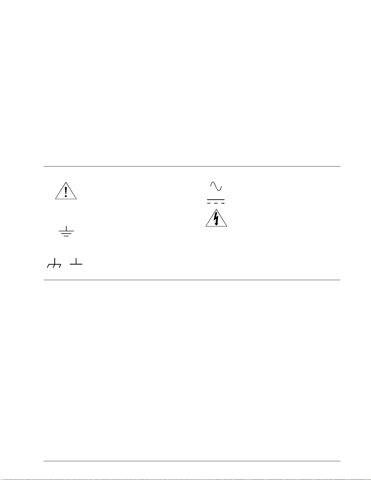
Safety Symbols
Instructi on m anual symbol affixed to prod uct. Indicates that the user must refer to the
manual for specific WARNING or CAUTION information to avoid personal injury
or damage t o t he pr oduct.
Alternating current (AC).
Direct current (DC).
Indicates the field wiring terminal that must
be connec t ed t o earth ground bef or e operating the equipm ent—protects agains t el ectrical shock in case of fault.
or
Frame or chassis ground terminal— typically connects to the equipment’s metal
frame.
WARNING
CAUTION
Indicate s ha zardous volta ges.
Calls at te nt i on t o a procedure, pr actice, or
condition that could cause bodily i nj ury o r
death.
Calls at te nt i on t o a procedure, pr actice, or condition that could possibl y ca use damage to
equipme nt or pe rm anent loss of dat a.
WARNINGS
The following general safety precautions must be obse rv ed during all phases of op er ati on, service, and re pai r of this product.
Failure to com p l y w i th t hese precautions or with sp ec i fi c w arnings else w here in this m anual violates saf et y st andards of des ign,
manufac ture, and int ended use of the produc t. A gi le n t Te chnologies assume s no l i ab i l it y for the customer’s fai lure to com p l y
with thes e requir em ents.
Ground the equipm en t: For Safety Class 1 equipment ( equipment ha vi ng a pr otective ea rt h t er minal), an uni nterruptib le sa fe ty earth
ground must be provided from t h e m a ins power source to the product input wiring ter minals or supplied power cable.
DO NOT operate the product in an explosiv e atmosphere or in the presence of flammabl e gases or fum es.
For continued protection against fire, replace the line fuse(s) only with fuse(s) of the same voltage and current rating and type.
DO NOT use re pai r ed fuses or short -c i rc ui te d fuse holders.
Keep away from live circuits: Operati ng personnel mu st not re m ove equipment covers or shields . P roc edures involv in g th e re moval
of covers or shi el ds are for use by service-train ed personnel onl y. U nder certain cond it i ons, dangerous voltages may exi st even with the
equipmen t s w itched off. To avoid dangerous e le ct r ic al shock, DO NOT perform procedures involving cover or shie ld removal unless
you are qualif ie d t o do so.
DO NOT operat e damaged equipmen t: Whe n e ver it is possible that the sa fe ty prot e ct ion features bui l t in t o t hi s pr oduct have been impaired, eit he r t hr ough physical damage, exc es si ve moisture, or any other reas on, R EMOVE POW ER and do not use the pr oduct until
safe opera tion can be verified by service- trained pers onnel. If necess ary, return the pr oduct to an Agi l ent Technologies Sales an d Ser vice Office for service and repair to ensure that safety features are maintained.
DO NOT ser vice or adjus t alone: Do not at te m pt internal service or adj us tm ent unless a not her person, ca pable of render in g fi rs t ai d
and resuscitation, is present.
DO NOT substitute par ts or modi fy equi pm e nt: Because of the danger of introducing additional hazards, do not instal l substitute
parts or perfo rm any unauthoriz ed modifica t io n to the product. R et ur n the product to an A gilent Technologies Sal es and Service Office
for service and repair to ensure that safety features are maintained.
4 Agilent E1445A Service Manual
Page 7
DECLARATION OF CONFORMITY
According to ISO/IEC Guide 22 and CEN/CENELEC EN 45014
Manufacturer’s Name:
Manufacturer’s Address:
Agilent Technologies, Incorporated
815 – 14th St. SW
Loveland, Colorado 80537
USA
Declares, that the product
Product Name:
Model Number:
Arbitrary Function Generator
E1445A
Product Options: This declaration covers all options of the above product(s).
Conforms with the following European Directives:
The product herewith complies with the requirements of the Low Voltage Directive 73/23/EEC and the EMC Directive 89/336/EEC
(including 93/68/EEC) and carries the CE Marking accordingly.
Conforms with the following product standards:
EMC Standard
IEC 61326-1:1997+A1:1998 / EN 61326-1:1997+A1:1998
CISPR 11:1990 / EN 55011:1991
IEC 61000-4-2:1995+A1:1998 / EN 61000-4-2:1995
IEC 61000-4-3:1995 / EN 61000-4-3:1995
IEC 61000-4-4:1995 / EN 61000-4-4:1995
IEC 61000-4-5:1995 / EN 61000-4-5:1995
IEC 61000-4-6:1996 / EN 61000-4-6:1996
IEC 61000-4-11:1994 / EN 61000-4-11:1994
Canada: ICES-001:1998
Australia/New Zealand: AS/NZS 2064.1
Limit
Group 1 Class A
4kV CD, 8kV AD
3 V/m, 80-1000 MHz
0.5kV signal lines, 1kV power lines
0.5 kV line-line, 1 kV line-ground
3V, 0.15-80 MHz I cycle, 100%
Dips: 30% 10ms; 60% 100ms
Interrupt > 95%@5000ms
The product was tested in a typical configuration with Agilent Technologies test systems.
Safety
IEC 61010-1:1990+A1:1992+A2:1995 / EN 61010-1:1993+A2:1995
Canada: CSA C22.2 No. 1010.1:1992
UL 3111-1: 1994
1 June 2001
Date
Ray Corson
Product Regulations Program Manager
Authorized EU-representative: Agilent Technologies Deutschland GmbH, Herrenberger Straβe 130, D 71034 Böblingen, Germany
For further information, please contact your local Agilent Technologies sales office, agent or distributor.
Revision: B.01 Issue Date: 1 June 2001 Document E1445A.DOC
Page 8

Notes
6 Agilent E1445A Service Manual
Page 9

Page 10

Page 11
Chapter 1
General Information
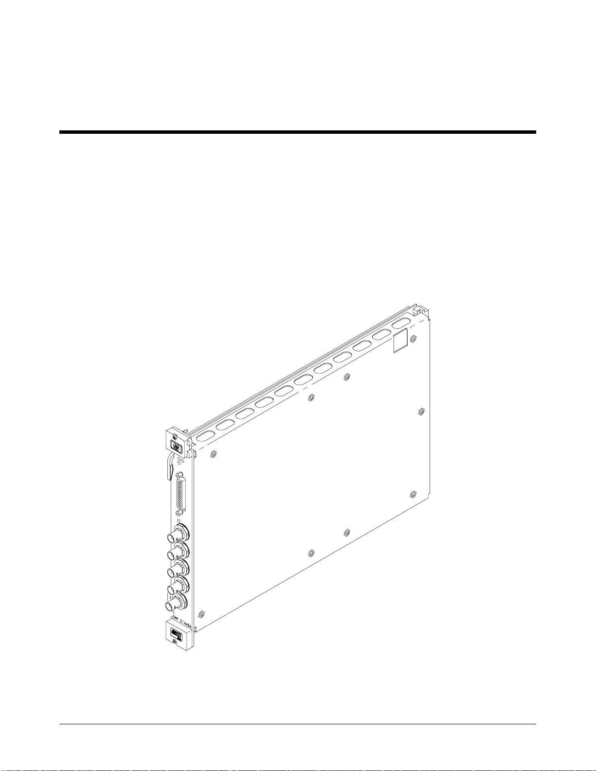
Introduction This manual co nta ins information required to test, trouble shoot, and repa ir
the Agilent E144 5A C-Siz e VXI Arbit rary Func tion Generator (AFG). See
the Agilent E1445A User’s Manual for additional informa ti on. Fi gur e 1-1
shows the Agile nt E1445A. This chapter inc ludes the followi ng se c ti ons:
• Introduction
• Safety Considerat ions
• Inspection/Shipping
• Environment
• AFG Description
• Recommended Test Equi pm en t
Figure 1-1. E1445A Arbitrary Function Generator
Agilent E1445A Service Manual General Information 9
Page 12

Safety
Considerations
This product is a Safet y Cl as s I instrument that i s provided with a protect ive
earth terminal when installed in the mainframe. The mainframe, AFG, and
all related documentat ion should be reviewed for familiarizat ion with safety
markings and instructions before opera ti on or se rv ic e .
Refer to the WARNINGS page (page 4) in this manual for a summary of
safety information. Safety information for preventive maintenance, testing,
and service follows and is also found throughout this manual.
Warnings and
Cautions
WARNING
This section cont ai ns W AR N INGS which must be followed for your
protection and CAUTIONS whi c h mus t be followed to avoid dama ge to the
equipment whe n pe rforming instrume nt maintenanc e o r repa ir .
SERVICE-TRAINED PERSONNEL ONLY. The information in this
manual is for service-trained personnel who are familiar with
electronic circuitry and are aware of the hazards involved. To
avoid personal injury or damage to the instrument, do not
perform procedures in this manual or do any servicing unless
you are qualified to do so.
CHECK MAINFRAME POWER SETTINGS. Before applying
power, verify t h at th e m ai n f ra m e se t ti n g m a tc hes the li ne
voltage and that the correct fuse is installed. An uninterruptible
safety earth ground must be provided from the main power
source to t he suppl ie d po we r co r d set .
GROUNDING REQUIREMENTS. Interruption of the protective
(grounding) conductor (inside or outside the mainframe) or
disconnecting the protective earth terminal will cause a
potential shock hazard that could result in personal injury.
(Grounding one conductor of a two-conductor outlet is not
sufficient protection.)
IMPAIRED PROTECTION. Whenever it is likely that instrument
protection has been impaired, the mainframe must be made
inoperative and be secu r ed against any u n intende d o p e rat i o n .
REMOVE POWER IF POSSIBLE. Some procedures in this
manual may be performed with power supplied to the
mainframe whil e p ro t e ct iv e covers ar e removed. Energy
available at many points may, if contacted, result in personal
injury. (If maintenance can be performed without power applied,
the power should be removed.)
10 General Information Agilent E1445A Service Manual
Page 13

WARNING
USING AUTOTRANSFORMERS. If the mainframe is to be
energized via an autotransformer (for vol tage reduction) make
sure the common terminal is connected to neutral (that is, the
grounded side of the main’s supply).
CAPACITOR VOLTAGES. Capacitors inside the mainframe may
remain charged even when the mainframe has been
disconnected from its source of supply.
USE PROPER FUSES. For continued protection against fire
hazard, replace the line fuses only with fuses of the sa me
current rating and type (such as normal blow, time delay, etc.).
Do not use repaired fuses or short-circuited fuseholders.
CAUTION
Static electricity is a major cause of component failure. To prevent
damage to the electrical components in the AFG, observe anti-static
techniques whenever working on the AFG.
Agilent E1445A Se rvice Man ual General Inform ation 11
Page 14
Inspection/
Shipping
This section de sc ri be s initial (in co ming) inspection and shipping guidelines
for t he AFG.
Inspection
WARNING
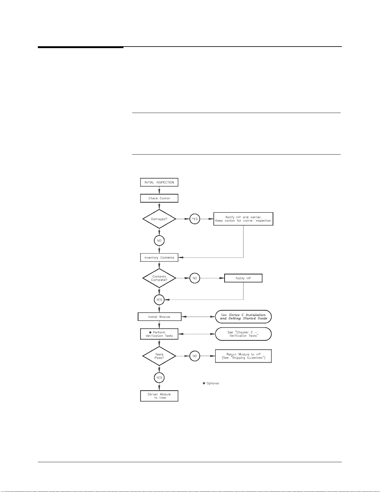
Initial
Use the steps in F igure 1-2 as guidelines to perform initial inspe c tion of
the AFG.
To avoid possible hazardous electrical shock, do not perform
electrical tests if there are signs of shipping damage to the
shipping container or to the instrument.
Figure 1-2. Initial (Incoming) Inspec tion Guidelines
12 General Information Agilent E1445A Service Manual
Page 15
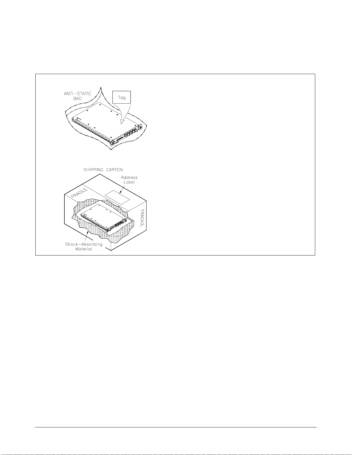
Shipping
Guidelines
Follow the step s in Figure 1-3 to retu rn the AFG to an Agilent Technologies
Sales and Support Offi ce or Ser vi ce Center.
1. Prepare the module
• Remove user wiring from terminal bloc k
• Attach tag to module th at identifies :
• Owner
• Model Number/Serial Number
• Service Required
• Place tagged devi ce in approved anti-static bag
2. Package the module
• Place packag ed mod ule in shipping carton*
• Place 75 to 100 mm (3 to 4 in ch es) of
shock-abs orbi ng material ar ound the module
• Seal the shipping c ont ai ne r s ecurely
• Mark the shipping container FRAGI LE
3. Ship the module to Agi lent Technologie s
• Place address lab el on s hip ping carton
• Send carton to Agilent Technologies
* We recommend that you use the same shipping materials as those used in factory packaging (available from
Agilent Technologies). For other (commerc ia l ly-available ) sh ipp ing ma te ri a ls, use a double-wall carton with
minimum 2.4 M Pa (350 psi) test.
Figure 1-3. Packaging/Shipping Guidelines
Agilent E1445A Se rvice Man ual General Inform ation 13
Page 16
Environment The recommended oper at in g env ironment for the Agilent E1445A
Agilent
AFG is:
Environment Temperature Humidity
Operating 0
Storage and
Shipment
AFG
Description
Specifications
Options
AFG
AFG
o
C to +55oC <65% relative (0oC to +40oC)
o
-40
C to +75oC <65% relative (0oC to +40oC)
The Agilent E1445A Ar bi tr a ry Function Generator is a VXIbus C -size ,
message-based instrument. The AFG can operate in a C-size VXIbus
mainframe usi ng a n Agi le nt E1405/E1406 Command Module a nd St a nda r d
Commands for Programmable Instruments (SCPI).
The AFG has 13 bits of resol ution (including sign). It uses a sequen cer
architecture, with 256K points of Segment storage and 32K point s of
Sequence storage. The AFG has two internal timebases, 40 MHz and
(app roximate l y) 42 .9 MHz.
AFG specificatio ns a re li sted in Appendix A of the Agi le nt E1445A User’s
Manual. These specifications are the performance standards or limits
against which the instru m ent may be teste d.
Arbitrary Waveform Ge ne rat ion Software for HP 9000 Serie s 30 0
computers c an be order e d as Opti on 005.
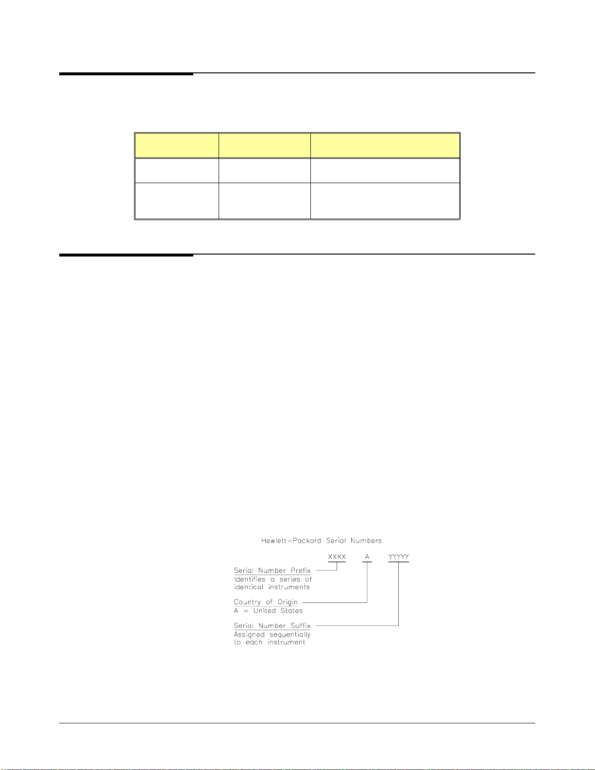
AFG
Serial Numbers
Figure 1-4 shows Agil en t Te chnologies’ serial num be r str uc ture . AFG’s
cove red by t h is man ual ar e iden tified by a s erial number pr efix listed on th e
title page.
Figure 1-4. Agilent Serial Numbers
14 General Information Agilent E1445A Service Manual
Page 17

Recommended
Test Equipment
Table 1-1 list s the te st equipment recommended f or te sting, adjusting, and
servicing the AFG. Essential requirements for each piece of test equipment
are described in the Requirements col um n .
Table 1-1. Recommended Test Equipment
Instrument Requirements Recommended
Model
Controller, GP-IB GP-IB compatibility as defined by IEEE
Standard 488-1988 and the identical
ANSI Standard MC1.1: SH1, AH1, T2,
TE0, L2, LE0, SR0, RL0, PP0, DC0,
DT0, and C1, 2, 3, 4, 5.
Mainframe Compatible with AFG Agilent E1401B/T or
Command Module 10 MHz Clk Out
TTL compatible Trig Out
Digital Multimeter DCV, ACV, 4-wire ohms w/offset comp Agilent 3458A O,P,A
Power Meter Frequency Range: 400 kHz - 10.8 MHz Agilent 8902A O,P,A
Power Sensor Frequency Range: 400 kHz - 10.8 MHz Agilent 11722A O,P,A
Counter Frequency Range: 100 Hz - 45 MHz Agilent 5334A/B O,P
Spectrum Analyzer Frequency Range: 100 kHz - 150 MHz Agilent 8566B O,P,A
HP 9000 Series 300
or
IBM Compatible PC
with HP BASIC
E1421B
Agilent E1405B or
Agilent E1406A
Use*
F,O,P,
A,T
F,O,P,
A,T
F,O,P,
A,T
Oscilloscope General Purpose
Bandwidth: 20 MHz
50 Ω feed-thru
termination
* F = Functional Verification, O = Operation Verification Tests, P = Performance Verification
Tests, A = Adjustments, T = Troubleshooting
50 ±0.10 Ω
Agilent 54111D F
Agilent 11048C O,P,A
Agilent E1445A Se rvice Man ual General Inform ation 15
Page 18

16 General Information Agilent E1445A Service Manual
Page 19

Chapter 2
Verification Tests
Introduction The three levels of test procedures described in this chapter are use d to
verify that the Agilen t E1445A:
• is fully functional (Fu nctional Verific a tion)
• meets selected testable specifications (Operation Verification)
• meets all testable specifications (Performance Verification)
WARNING
Test Conditions/
Procedures
Performance
Test Record
Do not perform any of the following verification tests unless
you are a qualified, service-trained technician and have read the
WARNINGS and CAUTIONS in Chapter 1.
See Table 1-1 for test equipment requ ir em e nts. You should complete the
Performance Verification tests at least once a year. For heavy use or severe
operating environments, perform the tests more often.
Before performing these tests, allow the AFG to warm up for at least one hour .
The temperature should be within
recent calibration), and between 18
The verificati on te sts assume that th e per son performing the te sts
understands how to operate the mainframe, the AFG, and specified test
equipment. T he te st pr oc e dur e s do not sp e cify equipment settin gs f or tes t
equipment, except in gener al terms. It is assumed that a qualified,
service-trained technicia n w ill se le c t a nd c onne c t the c ab le s, adap t ers, a n d
probes required f or the test.
The resul t s o f each Perf o rmance Verifi catio n t est m ay be recorded in Tabl e
2-11, Agilent E1445A Performance Test Recor d. This form can be copied.
o
±5
C of T
o
C and 28oC.
(the temperature of the most
cal
Verification Test
Examples
Each verificatio n te st proc e dur e include s a n e xa mpl e program that performs
the test. All exa mple programs a ssume the followin g co nf igur a tion:
• Controller is an HP 9000 Series 200/300 compu te r
• Programming language is HP BASIC
• AFG address is 70910
Agilent E1445A Service Manual Verification Tests 17
Page 20

Command Coupling Many of the AFG SCPI commands are value-coupled. In order to prevent
"Settings C onflict" errors, co uple d c o m ma nds must be sent con tiguously by
placing them in th e same program line, or by suppr e ssi ng the e nd- of - line
terminator . (Fo r m or e in fo rm a tion on command co upling and syntax, see
Chapter 1 of the Agilent E1445A User’s Manual). In HP BAS IC, the
end-of-line ter minator can be suppressed by linking th e commands with a
semi-colon (;) and a colon (:), as illustra te d below:
ROSC:SOUR INT1;
:TRIG:S OU R INT1
In the Example programs, these commands would appear as follows:
OUTPUT 70910;"ROSC:SOUR:INT1;";
OUTPUT 70910;":TRIG:SOUR:INT1"
Functional
Verification
NOTE
NOTE
The purpose of these te sts is to verify that the AFG is fun ctioni ng pr ope r ly
and that all front pa nel inputs and ou tputs are working . No a tte mpt is made
to verify that the A F G is me e ting specificati ons. Functional Ver ific a tion for
the AFG include s the f ollowing tests:
• Self-Test
• Ref In/Marker Out Test
• Start A r m I n Test
• Gate In Test
• Output Rela y Te st
For a quick functiona l ch eck of the AFG, per form only the Self-Test.
An example program tha t perfor m s al l of the Functional Verification tests is
included at the end of this section . An Agilen t E1405/E1406 Comma nd
Module is requir e d for this pr ogram.
Some of the tests use the "TRI G OUT" port of the Comma nd M odule. This
port uses negati ve logic, i.e., the hi gh v oltage is a logical 0 and the low
voltage is a logical 1.
18 Verificat ion Tes ts Agilent E1445A Serv ice Manu al
Page 21

Functional Ve rification: Self-Test
Description
The AFG self-test performs the following internal checks:
• internal interrupt lines
• waveform sele ct RAM
• segmen t se quence RAM
• waveform segment RAM
• DDS/NCO operation
• sine wave generation
• arbitrary waveform generation
• marker generation
• waveform cycle and arm counters
• sweep timer
• frequency-shift keying
• stop trigger
• DC analog paramete rs (amplitude, o ffset, attenuato rs , filters,
calibration DACs)
Test Procedure
1. Remove any connections to the AF G front panel .
2. Reset the AFG:
*RST;*CLS Reset AFG and clear
status registers
Execute the AFG self-test:
3.
*TST? Self-test command
Read the result. A "0" indicates that the test passed. A "1" indicates a
4.
failure. Read the error que ue using the SYST:ERR ? command until
the error message is "No error".
Agilent E1445A Service Manual Verification Tests 19
Page 22
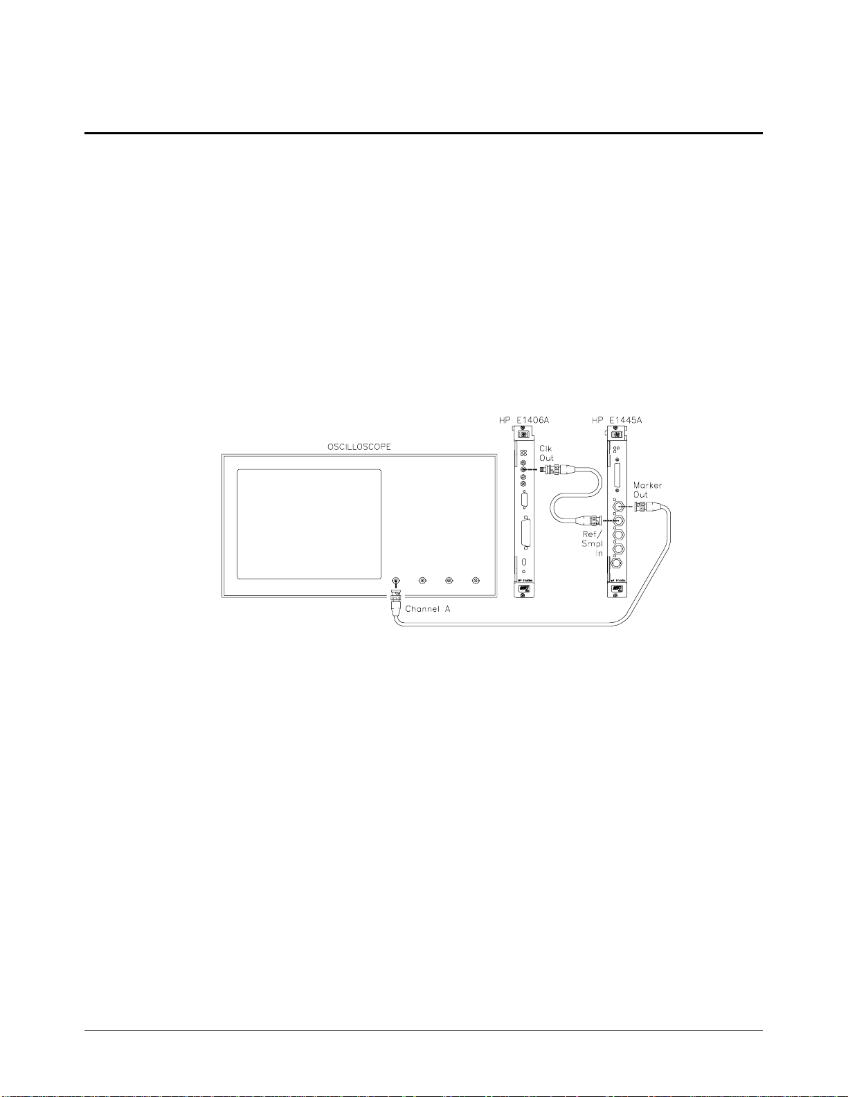
Funct ional Verification: Ref In/Marker Out Test
Description
The purpose of thi s te st is to check the Ref /S a mple In and Marker Ou t por ts.
An external ref e renc e is c onne cted to the Ref/S a mple In port and sent to the
Marker Out port.
Test Procedure
1. Reset the AFG:
*RST;*CLS Reset AFG and clear
2.
Set up equipme nt a s shown in Fi gur e 2-1 :
status registers
Figure 2-1. Ref/Sample In Test Setup
3. Set up the AFG to output the external ref ere nc e to the "Marker Out"
port:
ROSC:SOUR EXT External ref osci ll ato r
MARK:FEED "ROSC" Marker sour ce is RO SC
INIT:IMM Initiate
Verify that the scope shows a 10 MH z squa rewave .
4.
20 Verificat ion Tes ts Agilent E1445A Serv ice Manu al
Page 23
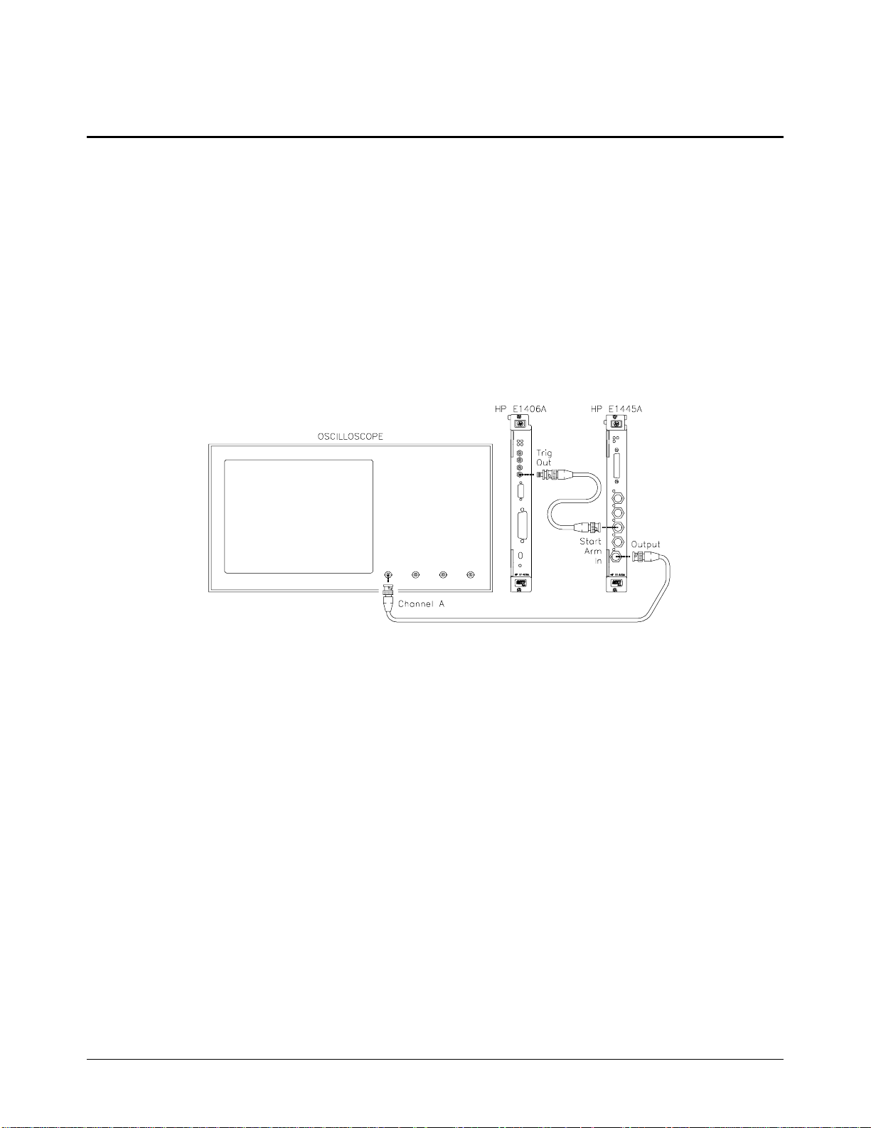
Functional Verification: Start Arm In Test
Description
The purpose of this test is to check the Start Arm In port. The "TRIG OUT"
port of the Command Module is used to send a Sta r t Arm signal to the AFG.
Test Procedure
1. Reset the AFG:
*RST;*CLS Reset AFG and clear
Set up equipme nt a s shown in Fi gur e 2-2 :
2.
status registers
Figure 2-2. Start Arm In Test Setup
3. Send the following comm a nds to the Command Module to output 0 V
to the "Trig Out" port:
*RST
OUTP:EXT:STAT ON
OUTP: EX T :SOUR IN T
OUTP:EXT:LEV 1
Agilent E1445A Service Manual Verification Tests 21
Page 24

Functional Verification: Start Arm In Test (cont’d)
Test Procedure
(cont’d)
4. Set up the AFG to output a 1 MHz sinewav e, w ith an external S ta rt
Arm source:
FREQ 1E6; Set fre q to 1 MHz
:VOLT 4VPP Set AFG amplitude
ARM:LAY2:SO UR EXT External Star t Arm
INIT:IMM Initiate
Verify that no signal appears on the scope. Send the following
5.
command to th e Co mm a nd Module to provide a Sta r t Arm signal to
the AFG:
OUTP:EXT:LEV 0
Verify that a 1 MHz sinewave appea r s on the sc ope.
6.
source
22 Verificat ion Tes ts Agilent E1445A Serv ice Manu al
Page 25
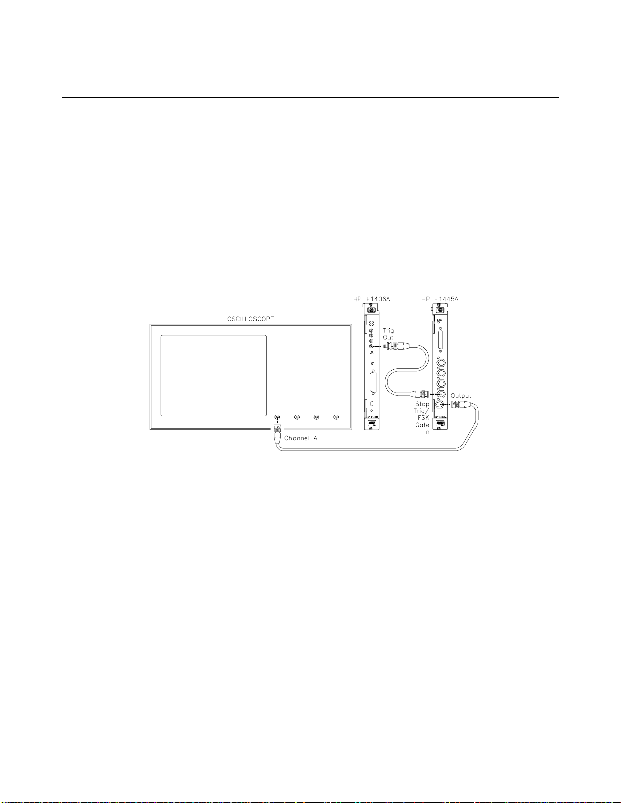
Functional Ve rification: G ate In Test
Description
The purpose of thi s te st is to check the gating function. The "TRIG OUT"
port of the Command Module is use d to gate the output .
Test Procedure
1. Reset the AFG:
*RST;*CLS Reset AFG and clear
Set up the equipm e nt a s shown in Figure 2-3.
2.
status registers
Figure 2-3. Gate In Test Setup
3. Send the following comm a nds to the Command M odule to enable the
"Trig Out" port:
*RST
OUTP:EXT:STAT ON
OUTP: EX T :SOUR IN T
Agilent E1445A Service Manual Verification Tests 23
Page 26

Functional Verification: Gate In Test (cont’d)
Test Procedure
(cont’d)
4. Set up the AFG to output a 1 MHz sinewave with an external gate
source:
TRIG:GATE:SOUR EXT; External gate source
:TRIG:GATE:ST AT O N; Enable gate
:FREQ 1E6; Set fre q to 1 MHz
:VOLT 4VPP Set AFG amplitude
INIT:IMM Initiate
Send the follow i ng c o mm and to the Comma nd Module to set th e
5.
level at the "Trig Out" por t to 5 V. Verify that the scope shows a 1
MHz sinewave.
OUTP:EXT:LEV 0
Send the follow i ng c o mm and to the Comma nd Module to set th e
6.
level at the "Trig Out" port to 0 V. Verify that the scope shows a DC
signal.
OUTP:EXT:LEV 1
24 Verificat ion Tes ts Agilent E1445A Serv ice Manu al
Page 27
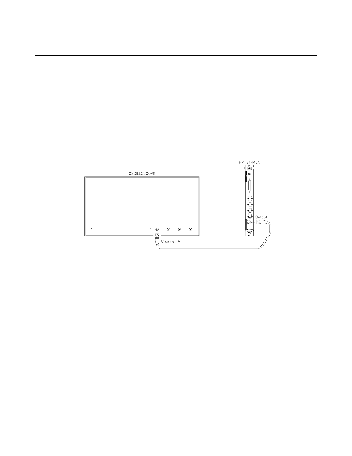
Funct ional Ve rifica tion: Output Relay Test
Description
The purpose of this te st is to check the output r e la y.
Test Procedure
1. Reset the AFG:
*RST;*CLS Reset AFG and clear
Set up equipme nt a s shown in Fi gur e 2-4 :
2.
status registers
Figure 2-4. Output Relay Test Setup
3. Set up the AFG to output a 1 MHz sinewave:
FREQ 1E6; Set fre q to 1 MHz
:VOLT 4VPP Set AFG amplitude
INIT:IMM Initiate
Verify that a 1 MHz sinewave appea r s on the sc ope.
4.
5. Disable the Output relay:
OUTP OFF
Verify that no signal appears on the scope.
6.
Agilent E1445A Service Manual Verification Tests 25
Page 28

Functional Verification
Example Progr am
This program pe rfor ms the Functional Verification Tests for the AF G . An Agilent E1405/E1406 Comm an d
Module is requir e d f or this te st.
10! RE-STORE "FUNC_TEST"
20 COM @Afg,@Cmd_mod,INTEGER Done
30 !
40 !--- ------- S e t u p I/O pa ths ---------50 ASSIGN @Afg TO 7091 0
60 ASSIGN @Cmd_mod TO 70900
70 !
80 !---------- Initialize AFG & Comm and M odule ---------90 Reset_afg
100 !
110 !Set up Command M odule ’ TRI G O UT’ port
120 OUTPUT @Cmd_m od;"*RST"
130 OUTPUT @Cmd_mod;"OUTP:EXT:STAT ON"
140 OUTPUT @Cmd_mod;"OUTP:EXT:SOUR INT"
150 !
160 !---------- Perform tests ---------170 CLEAR SCREEN
180 PRINT "Agilent E1445A FUNCTIONAL VERIFICATION TESTS"
190 PRINT
200 !
210 !Oscilloscope settings
220 PRINT "Set scope t o: 2 V/di v, . 02 usec/div"
230 PRINT
240 Wait_for_cont
250 !
260 CALL Self_test !Self-Test
270 CALL Ref_in !Ref In/Marker Out Test
280 !
290 !Oscilloscope settings
300 CLEAR SCREEN
310 PRINT "Set scope t o: 2 V/div, . 2 usec/div"
320 PRINT
330 Wait_for_cont
340 !
350 CALL Start_arm !Start Arm In Test
360 CALL Gate_in !Gate In Test
370 CALL Output_ relay !Output Relay Test
380 !
390 Quit: !
400 Reset_afg
410 CLEAR SCREEN
420 DISP "Functional Tes ts compl et ed. "
430 END
(Continued on ne xt pa ge )
26 Verificat ion Tes ts Agilent E1445A Serv ice Manu al
Page 29

Functional Verification
Example Program (cont’d)
450 !---------- Subprogram s ---------460 SUB Reset_afg
470 COM @Afg,@Cmd_mod,INTEGER Done
480 OUTPUT @Afg ;"* RS T; *CLS" !Reset AFG and clear Status re gi ster
490 WAIT 1
500 SUBEND
510 !
520 SUB Self_test
530 COM @Afg,@Cmd_mod,INTEGER Done
540 DIM Message$[255]
550 !
560 Reset_afg
570 !
580 CLEAR SCREEN
590 PRINT "SELF-TEST"
600 PRINT
610 !
620 !Test connections
630 PRINT "Remove any connections from the E1445A front panel."
640 PRINT "Press ’Conti nue’ t o in itiat e Sel f -Te st."
650 PRINT
660 Wait_for_cont
670 !
680 !Perform test
690 OUTPUT @Afg;"*TST?" !Self -test command
700 ENTER @Afg;Result !Get result
710 !
720 IF Result=0 THEN
730 PRINT "Self-test passed."
740 ELSE
750 PRINT "Self-test failed."
760 PRINT "The following err or (s) occurred:"
770 REPEAT
780 OUTPUT @Afg;"SYST:ERR?" !Check for errors
790 ENTER @Afg;Message$
800 PRINT " "&Message$
810 UNTIL POS(Message$,"No error")
820 END IF
830 Wait_for_cont
840 SUBEND
850 !
860 SUB Ref_in
870 COM @Afg,@Cmd_mod,INTEGER Done
880 !
(Continued on ne xt pa ge )
Agilent E1445A Service Manual Verification Tests 27
Page 30

Functional Verification
Example Program (cont’d)
890 Reset_afg
900 !
910 CLEAR SCREEN
920 PRINT "REF IN/MARKER OUT TEST"
930 PRINT
940 !
950 !Test connections
960 PRINT "Connect Scope to ’Marker Out’ on the E1445A."
970 PRINT "Connect Command Module ’Clk Out’ to ’Ref/Sample In’ on the E14 45A."
980 PRINT
990 Wait_for_cont
1000 !
1010 !Perform test
1020 OUTPUT @Afg;"ROSC:SOUR EXT" !External ref osc source
1030 OUTPUT @Afg;"MARK:FEED ""ROSC""" !Marker source is ’ROSC’
1040 OUTPUT @Afg;"INIT:IMM" !Initiate
1050 !
1060 PRINT "Verify th at the scope shows a 10 MHz squarewave."
1070 Wait_for_cont
1080 SUBEND
1090 !
1100 SUB Start_arm
1110 COM @Afg,@Cm d_m od,INTEGER Don e
1120 !
1130 Reset_afg
1140 !
1150 CLEAR SCREEN
1160 PRINT "START ARM TEST"
1170 PRINT
1180 !
1190 !Test connecti ons
1200 PRINT "Connect Sco pe t o th e E1445A Output."
1210 PRINT "Connect Com m and Module ’Trig Out’ to ’Start A rm In’ on th e E1445A."
1220 PRINT
1230 Wait_for_cont
1240 !
1250 !Set Command Mo dul e’s ’ TR IG OUT’ to 0V (E1405 uses neg logic )
1260 OUTPUT @Cmd_m od ;"O UTP :E XT: LEV 1"
1270 !
1280 !Perform test
1290 OUTPUT @Afg;"FREQ 1E6;"; !Set freq to 1 MHz
1300 OUTPUT @Afg;":VOLT 4VPP" !Set amplitude
1310 OUTPUT @Afg;"ARM:LAY2:SOUR EXT" !Start Arm source is EXT
1320 OUTPUT @Afg;"INIT:IMM" !Initiate
1330 !
(Continued on ne xt pa ge )
28 Verificat ion Tes ts Agilent E1445A Serv ice Manu al
Page 31

Functional Verification
Example Program (cont’d)
1340 PRINT "Verify th at no signal appears on the scope. "
1350 PRINT "Press ’Con tinu e’ to se nd a STA RT A RM . "
1360 PRINT
1370 Wait_for_cont
1380 !
1390 !Set ’TRIG OUT’ to 5V
1400 OUTPUT @Cmd_m od ;"O UTP :E XT: LEV 0"
1410 !
1420 PRINT "Verify th at the scope shows a 1 MHz sinewa ve. "
1430 Wait_for_cont
1440 SUBEND
1450 !
1460 SUB Gate_in
1470 COM @Afg,@Cm d_m od,INTEGER Don e
1480 !
1490 Reset_afg
1500 !
1510 CLEAR SCREEN
1520 PRINT "GATE IN TEST"
1530 PRINT
1540 !
1550 !Test connecti ons
1560 PRINT "Connect Sco pe t o th e E1445A Output."
1570 PRINT "Connect Com m and Mod ul e ’Trig O ut ’ to ’St op Tr ig/F SK /Ga te In’ on the E1445A."
1580 PRINT
1590 Wait_for_cont
1600 !
1610 !Perform test
1620 OUTPUT @Afg;"TRIG:GATE:SOUR EXT;"; !Gate source is EXT
1630 OUTPUT @Afg;":TRIG:GATE:STAT ON;"; !Enable gate
1640 OUTPUT @Afg;":FREQ 1E6;"; !Set freq to 1 MHz
1650 OUTPUT @Afg;":VOLT 4VPP" !Set amplitude
1660 OUTPUT @Afg;"INIT:IMM" !Initiate
1670 !
1680 PRINT "Verify th at the sig nal di splayed on the scope toggl es bet w een"
1690 PRINT "a 1 MHz sine w ave an d a D C signal at 1 secon d in te rva ls."
1700 !
1710 ON KBD ALL CALL Key_press
1720 DISP "Press an y key t o continue"
1730 !
1740 Done=0
1750 !Send pulses to ’T RIG O U T’ B NC unt il a ke y is pres sed
(Continued on ne xt pa ge )
Agilent E1445A Service Manual Verification Tests 29
Page 32

Functional Verification
Example Program (cont’d)
1760 REPEAT
1770 OUTPUT @Cmd_m od; " O UTP :E XT: LEV 1"
1780 WAIT 1
1790 OUTPUT @Cmd_m od; " O UTP :E XT: LEV 0"
1800 WAIT 1
1810 UNTIL Done
1820 OFF KBD
1830 SUBEND
1840 !
1850 SUB Output_ relay
1860 COM @Afg,@Cm d_m od,INTEGER Don e
1870 !
1880 Reset_afg
1890 !
1900 CLEAR SCREEN
1910 PRINT "OUTPUT RELAY TEST"
1920 PRINT
1930 !
1940 !Test connecti ons
1950 PRINT "Connect Sco pe t o th e E1445A Output."
1960 PRINT
1970 Wait_for_cont
1980 !
1990 !Perform test
2000 OUTPUT @Afg;"FREQ 1E6;"; !Set freq to 1 MHz
2010 OUTPUT @Afg;":VOLT 4VPP" !Set amplitude
2020 OUTPUT @Afg;"INIT:IMM" !Initiate
2030 !
2040 PRINT "Verify th at the scope shows a 1 MHz sinewa ve. "
2050 PRINT "Press ’Con tinu e’ to disa bl e th e E1445A output."
2060 PRINT
2070 Wait_for_cont
2080 !
2090 OUTPUT @Afg;"OUTP OFF" !Open Output relay
2100 PRINT "Verify th at no signal appears on the scope. "
2110 Wait_for_cont
2120 SUBEND
2130 !
(Continued on ne xt pa ge )
30 Verificat ion Tes ts Agilent E1445A Serv ice Manu al
Page 33

Functional Verification
Example Program (cont’d)
2140 SUB Key_press
2150 COM @Afg,@Cm d_m od,INTEGER Don e
2160 Done=1
2170 DISP
2180 SUBEND
2190 !
2200 SUB Wait_for_ cont
2210 DISP "Press ’Cont inue’ when ready"
2220 PAUSE
2230 DISP
2240 SUBEND
Agilent E1445A Service Manual Verification Tests 31
Page 34

Operation
Verification
Operation Verification is a subset of the Performan ce Ve rifi cati on te sts that
follow. For the AFG, Opera tion Verification consists of the fo llow ing tests:
• DC Accuracy
• AC Accuracy
• Total Harmonic Dis tortion
Performance
Verification
The procedures in this section are used to test the AFG’s electrical
performance using the spe c ifica tions in Appendix A of the Agilent E1445A
User’s Manual as the performance standards. These tests are suitable for
incoming inspe c tion, troublesho oting, and preventive mainten an ce. Th e
results of the Perf o rma n c e Verif ic a tion tests should be recorded in the
Performance Test Recor d (Table 2-11).
Performance Verification includes the following tests:
Test # Test Name
2-1
2-2
2-3
2-4
2-5
2-6
2-7
2-8
2-9
2-10
DC Zeros
DC Accuracy
DC Offset
AC Accuracy
AC Flatness - 250 kHz filter
AC Flatness - 10 MHz filter
Frequency Accuracy
Duty Cycle
Total Harmonic Distortion
Spurious/Non-harmonic Distortion
32 Verificat ion Tes ts Agilent E1445A Serv ice Manu al
Page 35

Test 2-1: DC Zeros
Description
Equipment Setup
The purpose of thi s te st is to verify that the AFG me e ts it s spe c if ic at ions for
DCV accuracy for an output of zero volts. An arbitrary waveform
consisting of zer os is used. The amplitude is va r ie d in or de r to te st e a ch
attenuator.
• Connect equipm e nt as shown in Figure 2-5
• Set DMM to: DCV, 100 mV range
Figure 2-5. Equipment Setup for Test 2-1 thru Test 2-4
Test Procedure
1. Reset the AFG:
*RST;*CLS Reset AFG and clear
status registers
Delete all sequence s and segment s from memory :
2.
LIST:SSEQ:DEL:ALL Delete all sequence s
LIST:SEGM:DEL:ALL Delete all segments
Agilent E1445A Service Manual Verification Tests 33
Page 36

Test 2-1: DC Zeros (cont’d)
Test Procedure
(cont’d)
3. Creat e a user-defined waveform made up of zeros:
4.
LIST:SEGM:SEL ZE ROS Select segment name
LIST:SEGM:DEF 8 # of segment points
LIST:SEGM:VOLT 0,0,0,0,0,0,0,0 Segment list
LIST:SSEQ:SEL DC _ZERO S Select sequence name
LIST:SSEQ:D EF 1 # of segments
LIST:SSEQ:SEQ ZEROS Sequence list
Set up the AFG to output the waveform defined above:
ROSC:SOUR CLK10; Select 10 MHz clock
:VOLT MAX; Set amplitude
:OUTP:LOAD INF ; Infinite load
:FUNC USER Select user waveform
FUNC:USER DC_ZEROS Select sequence
INIT:IMM Initiate waveform
Perform steps 5 - 7 for each amplitude listed in Table 2-1:
5. Set the AFG output filter as specified in Ta ble 2- 1. Use th e
appropriate command(s) below:
OUTP:FILT OFF Disable filter
or
OUTP:FILT:FREQ 250KHZ Select 250 kHz filte r
OUTP:FILT ON Enabl e filter
or
OUTP:FILT:FREQ 10MHZ Select 10 MHz filter
OUTP:FILT ON Enabl e filter
Set the AFG output amplitude:
6.
VOLT <amplitude> Se t ampl it ude
where <amplitude> is the value specified in Table 2-1.
7. Trigger the DMM and record the reading in Table 2-11.
34 Verificat ion Tes ts Agilent E1445A Serv ice Manu al
Page 37

Test 2-1: DC Zeros (cont’d)
Test Procedure
(cont’d)
Table 2-1. DC Zeros Test Points
Attenuation
(dB)
0
.99
1
2
4
8
13
14
30
0
.99
1
2
4
8
13
14
30
Amplitude
(volts)
10.23750
9.13469
9.12416
8.13192
6.45941
4.07560
2.29187
2.04263
0.32372
10.23750
9.13469
9.12416
8.13192
6.45941
4.07560
2.29187
2.04263
0.32372
Filter Test Limits
(volts)
None
None
None
None
None
None
None
None
None
250 kHz
250 kHz
250 kHz
250 kHz
250 kHz
250 kHz
250 kHz
250 kHz
250 kHz
0 ± 0.0220
0 ± 0.0220
0 ± 0.0220
0 ± 0.0220
0 ± 0.0220
0 ± 0.0220
0 ± 0.0220
0 ± 0.0044
0 ± 0.0044
0 ± 0.0220
0 ± 0.0220
0 ± 0.0220
0 ± 0.0220
0 ± 0.0220
0 ± 0.0220
0 ± 0.0220
0 ± 0.0044
0 ± 0.0044
10 MHz
10 MHz
10 MHz
10 MHz
10 MHz
10 MHz
10 MHz
10 MHz
10 MHz
0 ± 0.0220
0 ± 0.0220
0 ± 0.0220
0 ± 0.0220
0 ± 0.0220
0 ± 0.0220
0 ± 0.0220
0 ± 0.0044
0 ± 0.0044
.99
13
14
30
0
1
2
4
8
10.23750
9.13469
9.12416
8.13192
6.45941
4.07560
2.29187
2.04263
0.32372
Agilent E1445A Service Manual Verification Tests 35
Page 38

Test 2-1: DC Zeros (cont’d)
Example Progr am
This program perform s the DC Zero s te st. An arbit rar y wave fo rm, con sisting of zeros, is used with va rious
amplitudes to test a variety of attenuator and filter combin at ion s .
10! RE-STORE "DC_ZEROS"
20 COM @Afg
30 DIM Attn(1:9),Vout(1:9)
40 !
50 !---------- Set up I/O path and reset AFG ---------60 ASSIGN @Afg TO 70910
70 OUTPUT @Afg;"*RST;*CLS" !Reset AFG
80 !
90 !---------- Initialize variables ---------100 DATA 0,.99,1,2, 4,8, 13, 14, 30
110 READ Attn(*) !Read in attenuations
120 !
130 DATA 10.2375,9. 13469,9.12416,8. 13192,6.45941,4. 0756
140 DATA 2.29187,2. 04263,0.32372
150 READ Vout(*)
160 !
170 !---------- Set up DMM ---------180 PRINT "Set up DMM:"
190 PRINT
200 PRINT " Function -- DCV"
210 PRINT " Range -- 100 mV"
220 PRINT
230 PRINT "Connect D M M HI and LO t o AFG O ut put. "
240 DISP "Press ’Conti nue’ when ready"
250 PAUSE
260 CLEAR SCREEN
270 !
280 !---------- Set u p A F G ---------290 OUTPUT @Afg;"*RST" !Reset AFG
300 OUTPUT @Afg; "LIST:SSEQ:DEL:ALL " !Delete all sequenc es
310 OUTPUT @Afg;"LIST:SEGM:DEL:ALL" !Delete all segments
320 WAIT .5
330 OUTPUT @Afg;"ROSC:SOUR CLK10;"; !10MHZ clock
340 OUTPUT @Afg;":VOLT MAX;"; !MAX output
350 OUTPUT @Afg;":OUTP:LOAD INF;"; !Infinite load
360 OUTPUT @Afg;":FUNC USER" !User waveform
370 !
380 CALL Def_seq_zeros !Define wa vef or m
390 OUTPUT @Afg;"FUNC:USER DC_ZEROS" !Select sequence
400 OUTPUT @Afg;"INIT:IMM"
410 !
420 !---------- Perform te s t ------ ---430 PRINT "ATTEN","FILTER","AMPLITUDE"
(Continued on ne xt pa ge )
36 Verificat ion Tes ts Agilent E1445A Serv ice Manu al
Page 39

Test 2-1: DC Zeros (cont’d)
Example Program (cont’d)
440 PRINT
460 FOR Filter=0 TO 2
470 SELECT Filter
480 CASE 0 !No filter
490 OUTPUT @Afg;"OUTP:FILT OFF"
500 Filter$="NONE"
510 CASE 1 !250KHZ filter
520 OUTPUT @Afg;"OUTP:FILT: FREQ 250KH Z"
530 OUTPUT @Afg;"OUTP:FILT ON"
540 Filter$="250 kHz"
550 CASE 2 !10MHZ filter
560 OUTPUT @Afg;"OUTP:FILT:FREQ 10MHZ"
570 OUTPUT @Afg;"OUTP:FILT ON"
580 Filter$="10 MHz"
590 END SELECT
600 !
610 FOR I=1 TO 9 !Loop through atten ’s
620 OUTPUT @Afg;":VOLT "&VAL$(Vout(I)) !Set AFG amplitude
630 PRINT Attn(I),Filter$,Vout(I)
640 !
650 DISP "Record DMM reading, the n pre ss ’C ont inue’ "
660 PAUSE
670 DISP
680 NEXT I !Next attenuation
690 PRINT
700 NEXT Filter !Next filter
710 !
720 OUTPUT @Afg;"*RST;*CLS" !Reset AFG
730 END
740 !
750 SUB Def_seq_zer o s
760 COM @Afg
770 OUTPUT @Afg;"LIST:SEGM:SEL ZEROS" !Segment name
780 OUTPUT @Afg;"LIST:SEGM:DEF 8" !Segment length
790 OUTPUT @Afg;"LIST :SEGM : VO LT 0, 0,0, 0, 0, 0,0, 0" !Voltage points
800 !
810 OUTPUT @Afg;"LIST :SSEQ :S EL D C_ZEROS" !Sequence name
820 OUTPUT @Afg;"LIST:SSEQ:DEF 1" !# of segments
830 OUTPUT @Afg;"LIST:SSEQ:SEQ ZEROS" !Segment list
840 SUBEND
Agilent E1445A Service Manual Verification Tests 37
Page 40

Test 2-2: DC Accuracy
Description
Equipment Setup
Test Procedure
The purpose of thi s te st is to verify that the AFG me e ts it s spe c if ic at ions for
DC accuracy.
• Connect equipm e nt as shown in Figure 2-5
• Set DMM to DCV, autorange
1. Reset the AFG:
*RST;*CLS Reset AFG and clear
status registers
Set up the AFG to output a DC signal:
2.
FUNC DC; Select DC waveform
:OUTP:LOAD INF ; Infinite load
:VOLT MAX Set amplitude
Perform steps 3 - 5 for each amplitude listed in Table 2-2:
3. Set up the AFG output filter as specified in Table 2-2. Use the
appropriate command(s) below:
OUTP:FILT OFF Disable filter
or
OUTP:FILT:FREQ 250KHZ Select 250 kHz filte r
OUTP:FILT ON Enabl e filter
or
OUTP:FILT:FREQ 10MHZ Select 10 MHz filter
OUTP:FILT ON Enabl e filter
Set the AFG output amplitude:
4.
VOLT <amplitude> Se t ampl it ude
where <amplitude> is the value specified in Table 2-2.
5. Trigger the DMM and record the reading.
38 Verificat ion Tes ts Agilent E1445A Serv ice Manu al
Page 41

Test 2-2: DC Accuracy (cont’d)
Test Procedure
(cont’d)
Table 2-2. DC Accuracy Test Points
Amplitude
(volts)
10.2375
5.0
0.0
-5.0
-10.24
10.2375
-10.24
10.2375
-10.24
Example Progr am
This program pe rfor m s the D C Ac curacy test.
10! RE-STORE "DC_LEVELS"
20 DIM Vout(1:9),Filter(1:9)
30 !
40 !---------- Set up I/O path and reset AFG ----------50 ASSIGN @Afg TO 70910
60 OUTPUT @Afg;"*RST;*CLS" !Reset AFG
70 !
80 !---------- Initialize variables ---------90 DATA 10.2375,5.0,0, -5 .0,-10. 24,10.2375,-10.24,10.2375,-10.24
100 READ Vout(*)
110 !
120 DATA 0,0,0,0,0,1,1,2,2
130 READ Filter(*)
140 !
150 !--------- - Set up DMM ---------160 CLEAR SCREEN
170 PRINT "Set up DMM:"
180 PRINT
190 PRINT " Function -- DCV"
200 PRINT " Range -- AUTO"
210 PRINT
220 PRINT "Connect DMM HI and LO to AFG Output."
230 DISP "Press ’Continue’ w hen r eady "
240 PAUSE
250 CLEAR SCREEN
Filter Test Limits
(volts)
None
None
None
None
None
250 kHz
250 kHz
10 MHz
10 MHz
10.2375 ± 0.0512
5.0 ± 0.0355
0.0 ± 0.0205
-5.0 ± 0.0355
-10.24 ± 0.0512
10.2375 ± 0.0512
-10.24 ± 0.0512
10.2375 ± 0.0512
10.24 ± 0.0512
Agilent E1445A Service Manual Verification Tests 39
Page 42

Test 2-2: DC Accuracy (cont’d)
Example Program (cont’d)
270 !--------- - Set up AFG ---------280 OUTPUT @Afg;"*RST" !Reset AFG
290 WAIT .5
300 OUTPUT @Afg;"FUNC DC;"; !DC function
310 OUTPUT @Afg;":OUTP:LOAD INF;"; !Infinite load
320 OUTPUT @Afg;":VOLT MAX" !MAX output
330 !
340 !---------- Perform test ---------350 PRINT "FILTER","AMPLITUDE"
360 PRINT
370 !
380 FOR I=1 TO 9
390 SELECT Filter(I)
400 CASE 0
410 OUTPUT @Afg;"OUTP:FILT OFF" !No filter
420 Filter$="NONE"
430 CASE 1
440 OUTPUT @Afg;"OUTP:FILT:FREQ 250KHZ" !250kHz filter
450 OUTPUT @Afg;"OUTP:FILT ON"
460 Filter$="250 kHz"
470 CASE 2
480 OUTPUT @Afg;"OUTP:FILT:FREQ 10MHZ" !10MHz filter
490 OUTPUT @Afg;"OUTP:FILT ON"
500 Filter$="10 M Hz"
510 END SELECT
520 !
530 OUTPUT @Afg;"VOLT "&VAL$(Vout(I)) !Set amplitude
540 PRINT Filter$,Vout(I)
550 !
560 DISP "Record DMM reading, then press ’Continue’ "
570 PAUSE
580 DISP
590 NEXT I
600 !
610 OUTPUT @Afg;"*RST;*CLS" !Reset AFG
620 END
40 Verificat ion Tes ts Agilent E1445A Serv ice Manu al
Page 43

Test 2-3: DC Offset
Description
Equipment Setup
Test Procedure
The purpose of thi s te st is to verify that the AFG me e ts it s spe c if ic at ions for
DC offset accuracy.
• Connect equipm e nt as shown in Figure 2-5
• Set DMM to DCV, autorange
1. Reset the AFG:
*RST;*CLS Reset AFG and clear
status registers
Delete all sequence s and segment s from memory :
2.
LIST:SSEQ:DEL:ALL Delete all sequence s
LIST:SEGM:DEL:ALL Delete all segments
Create a user-defined wave form made up of zeros:
3.
LIST:SEGM:SEL ZE ROS Select segment name
LIST:SEGM:DEF 8 # of segment points
LIST:SEGM:VOLT 0,0,0,0,0,0,0,0 Segment list
LIST:SSEQ:SEL DC _ZERO S Select sequence name
LIST:SSEQ:D EF 1 # of segments
LIST:SSEQ:SEQ ZEROS Sequence list
Set up the AFG to output the waveform defined above:
4.
ROSC:SOUR CLK10; Select 10 MHz clock
:OUTP:LOAD INF ; Infinite load
:VOLT MAX; Set amplitude
:FUNC USER Select user waveform
FUNC:USER DC_ZEROS Select sequence
INIT:IMM Initiate waveform
Agilent E1445A Service Manual Verification Tests 41
Page 44

Test 2-3: DC Offset (cont’d)
Test Procedure
(cont’d)
Perform steps 5 - 7 for eac h offset listed in Table 2- 3:
5. If necessary, change the AFG output amplitude:
6. Set AFG offset voltage:
7. Trigger the DMM and record the reading.
VOLT:OFFS 0; Set offset to 0
:VOLT <amplitude> Set amplitude
where <amplitude> is the value specified in Table 2-3.
VOLT:OFFS <offset> Set offset
where <offset> is the valu e sp ecif ie d in Table 2-3.
Table 2-3. DC Offset Test Points
Offset
(volts)
9.755
4.000
-4.000
-9.755
2.000
-2.000
Amplitude
(volts)
2.29189
2.29189
2.29189
2.29189
0.40756
0.40756
Test Limits
(volts)
9.755 ± 0.1196
4.0 ± 0.0620
-4.0 ± 0.0620
-9.755 ± 0.1196
2.0 ± 0.0244
-2.0 ± 0.0244
42 Verificat ion Tes ts Agilent E1445A Serv ice Manu al
Page 45

Test 2-3: DC Offset (cont’d)
Example Progr am
This program performs the DC Offset Test .
10! RE-STORE "DC_OFFSET"
20 COM @Afg
30 DIM Offset(1:6)
40 !
50 !---------- Set up I/O path and reset AFG ---------60 ASSIGN @Afg TO 70910 !AFG I/O path
70 OUTPUT @Afg;"*RST;*CLS" !Reset AFG
80 !
90 !---------- Initialize variables ---------100 DATA 9.755,4.0,- 4. 0,-9.755,2.0,-2.0
110 READ Offset(*) !Read in offsets
120 !
130 Vout_old=0 !Initialize
140 !
150 !---------- Set up DMM ---------160 CLEAR SCREEN
170 PRINT "Set up DMM:"
180 PRINT
190 PRINT " Function -- DCV"
200 PRINT " Range -- AUTO"
210 PRINT
220 PRINT "Connect D M M HI and LO t o AFG O ut put. "
230 DISP "Press ’Conti nue’ when ready"
240 PAUSE
250 CLEAR SCREEN
260 !
270 !---------- Set u p A F G ---------280 OUTPUT @Afg;"*RST" !Reset AFG
290 OUTPUT @Afg; "LIST:SSEQ:DEL:ALL " !Delete all sequenc es
300 OUTPUT @Afg;"LIST:SEGM:DEL:ALL" !Delete all segments
310 WAIT .5
320 OUTPUT @Afg;"ROSC:SOUR CLK10;"; !10MHz clock
330 OUTPUT @Afg;":OUTP:LOAD INF;"; !Infinite load
340 OUTPUT @Afg;":VOLT MAX;"; !MAX output
350 OUTPUT @Afg;":FUNC USER" !User waveform
360 !
370 CALL Def_seq_zeros !Define sequence of zer os
380 OUTPUT @Afg;"FUNC:USER DC_ZEROS" !Select sequence
390 !
400 !---------- Perform te s t ------ ---410 PRINT "AMPLITUDE" , " OFF S ET"
420 PRINT
430 !
(Continued on ne xt pa ge )
Agilent E1445A Service Manual Verification Tests 43
Page 46

Test 2-3: DC Offset (cont’d)
Example Program (cont’d)
440 FOR I=1 TO 6
450 IF I<=4 THEN
460 Vout=2.2919
470 ELSE
480 Vout=.40756
490 END IF
500 !
510 IF Vout<>Vout_old THEN
520 !Set offset to zero before changing am pl itu de
530 OUTPUT @Afg;":VOLT:OFFS 0;";
540 OUTPUT @Afg;":VOLT "&VAL$(Vout)&";";
550 END IF
560 !
570 OUTPUT @Afg;":VOLT:OFFS "&VAL$(Offset(I))!Set offset
580 PRINT Vout,Offset(I)
590 !
600 DISP "Record DMM readin g, then pre ss ’C ont inue’ "
610 PAUSE
620 DISP
630 Vout_old=Vout
640 NEXT I !Next attenuation
650 !
660 OUTPUT @Afg;"*RST;*CLS" !Reset AFG
670 END
680 !
690 SUB Def_seq_zer o s
700 COM @Afg
710 OUTPUT @Afg;"LIST:SEGM:SEL ZEROS" !Segment name
720 OUTPUT @Afg;"LIST:SEGM:DEF 8" !Segment length
730 OUTPUT @Afg;"LIST :SEGM : VO LT 0, 0,0, 0, 0, 0,0, 0" !Voltage points
740 !
750 OUTPUT @Afg;"LIST :SSEQ :S EL D C_ZEROS" !Sequence name
760 OUTPUT @Afg;"LIST:SSEQ:DEF 1" !# of segments
770 OUTPUT @Afg;"LIST:SSEQ:SEQ ZEROS" !Segment list
780 SUBEND
44 Verificat ion Tes ts Agilent E1445A Serv ice Manu al
Page 47

Test 2-4: AC Accuracy
Description
Equipment Setup
Test Procedure
The purpose of thi s te st is to verify that the AFG me e ts it s spe c if ic at ions for
AC accuracy at 1 kHz.
• Connect equipm e nt as shown in Figure 2-5
• Set DMM to ACV, autorange
1. Reset the AFG:
*RST;*CLS Reset AFG and clear
status registers
Set up the AFG to output a 1 kHz sinewave:
2.
FREQ 1E3; Set fre q to 1 kHz
:VOLT MAX; Set to max amplitude
:OUTP:LOAD INF Infinite load
CAL:STAT:AC OFF AC corrections off
INIT:IMM Initiate waveform
Perform steps 3 - 5 for e ac h amplitude and filte r listed in Table 2-4:
3. Set up AFG output filter as specified in Table 2-4. Use the
appropriate command(s) below:
OUTP:FILT OFF Disable filter
or
OUTP:FILT:FREQ 250KHZ Select 250 kHz filte r
OUTP:FILT ON Enabl e filter
or
OUTP:FILT:FREQ 10MHZ Select 10 MHz filter
OUTP:FILT ON Enabl e filter
Agilent E1445A Service Manual Verification Tests 45
Page 48

Test 2-4: AC Accuracy (cont’d)
Test Procedure
(cont’d)
4. Set the AFG output amplitude:
VOLT <amplitude>VRMS Set amplitude
where <amplitude> is the value specified in Table 2-4.
5. Trigger the DMM and record the reading.
Table 2-4. AC Accuracy Test Points
Amplitude
(volts rms)
7.2390
6.4500
5.7500
4.5660
2.8818
1.4444
0.2290
7.2390
7.2390
Filter Test
Limits
±(dB)
None
None
None
None
None
None
None
250 kHz
10 MHz
0.10
0.15
0.15
0.15
0.15
0.15
0.15
0.10
0.10
46 Verificat ion Tes ts Agilent E1445A Serv ice Manu al
Page 49

Test 2-4: AC Accuracy (cont’d)
Example Progr am
This program performs the AC Accuracy Test.
10! RE-STORE "AC_LEVELS"
20 DIM Vout(1:9),Filter(1:9 )
30 !
40 !---------- Set up I/O path and reset AFG ---------50 ASSIGN @Afg TO 70910
60 OUTPUT @Afg;"*RST;*CLS" !Reset AFG
70 !
80 !---------- Initialize variables ---------90 DATA 7.239,6.45,5. 75,4. 566,2.8818,1.4 444, . 229,7.239,7.239
100 READ Vout(*)
110 !
120 DATA 0,0,0,0,0, 0,0, 1, 2
130 READ Filter(*)
140 !
150 !---------- Set up DMM ---------160 CLEAR SCREEN
170 PRINT "Set up DMM:"
180 PRINT
190 PRINT " Function -- ACV"
200 PRINT " Range -- AUTO"
210 PRINT
220 PRINT "Connect D M M HI and LO t o AFG O ut put. "
230 DISP "Press ’Conti nue’ when ready"
240 PAUSE
250 CLEAR SCREEN
260 !
270 !---------- Set u p A F G ---------280 OUTPUT @Afg;"*RST" !Reset AFG
290 WAIT .5
300 OUTPUT @Afg;"FREQ 1E3;"; !Set freq to 1 kHz
310 OUTPUT @Afg;":VOLT MAX;"; !MAX amplitude
320 OUTPUT @Afg;":OUTP:LOAD INF" !Infinite load
340 OUTPUT @Afg;"CAL:STAT:AC OFF" !AC corrections off
350 OUTPUT @Afg;"INIT:IMM" !Initiate
360 WAIT .5
370 !
380 !---------- Perform te s t ------ ---390 PRINT "FILTER","AMPLITUDE"
400 PRINT
410 !
(Continued on ne xt pa ge )
Agilent E1445A Service Manual Verification Tests 47
Page 50

Test 2-4: AC Accuracy (cont’d)
Example Program (cont’d)
420 FOR I=1 TO 9
430 SELECT Filter(I)
440 CASE 0
450 OUTPUT @Afg;"OUTP:FILT OFF" !No filter
460 Filter$="NONE"
470 CASE 1
480 OUTPUT @Afg;"OUTP:F ILT: FR EQ 250KH Z" !250 kHz filter
490 OUTPUT @Afg;"OUTP:FILT ON"
500 Filter$="250 kHz"
510 CASE 2
520 OUTPUT @Afg;"OUTP:FILT:FREQ 10MHZ" !10 MHz filter
530 OUTPUT @Afg;"OUTP:FILT ON"
540 Filter$="10 MHz"
550 END SELECT
560 OUTPUT @Afg;":VOLT "&VAL$(Vout(I))&"VRMS" !Set amplitude
570 PRINT Filter$,Vout(I)
580 WAIT .5
590 !
600 DISP "Record DMM readin g, then pre ss ’C ont inue’ "
610 PAUSE
620 DISP
630 NEXT I
640 !
650 OUTPUT @Afg;"*RST;*CLS" !Reset AFG
660 END
48 Verificat ion Tes ts Agilent E1445A Serv ice Manu al
Page 51

Test 2-5: AC Flatness - 250 kHz Filter
Description
The purpose of thi s te st is to verify that the AFG me e ts it s spe c if ic at ions for
AC flatness with the 250 kHz filter enabled.
Equipment Setup
• Connect equipm e nt as shown in Figure 2-6
• Set DMM to ACV, autorange
Test Procedure
Figure 2-6. Equipment Setup for Test 2-5 and Test 2-6
1. Reset the AFG:
*RST;*CLS Reset AFG and clear
Set up the AFG to output a 24 dBm sinewa ve with the 250 kHz filter
2.
enabled:
VOLT 24DBM; Set amplitude
:OUTP:LOAD 50 50 ohm load
OUTP:FILT:FREQ 250KHZ 250 kHz filter
OUTP:FILT ON Enabl e filter
INIT:IMM Initiate waveform
status registers
Agilent E1445A Service Manual Verification Tests 49
Page 52

Test 2-5: AC Flatness - 250 kHz Filter (cont’d)
Test Procedure
(cont’d)
3. Set the AFG output to the reference frequency (1 kHz):
FREQ 1000 Set frequency
Measure the amplitude with the DMM and c onvert the reading to
4.
dBm. Note the resul t fo r us e in ste p 6:
Reference Level (dBm) = 20 × log ïReading (volts)ï+13.0103
Perform steps 5 - 6 for eac h frequency lis te d in Table 2- 5:
5. Set the AFG output:
FREQ <frequency> Set frequency
where <frequency> is the value spe cified in Table 2-5.
6. Measure the amplitude with the DMM and convert the reading to
dBm. Calculate and record the error relative to the reference level
calculated in step 4:
Reading (dBm) = 20 × log ïReading (volts)ï+13.0103
Error (dB) = Reading (dBm) − Reference Level (dBm )
50 Verificat ion Tes ts Agilent E1445A Serv ice Manu al
Page 53

Test 2-5: AC Flatness - 250 kHz Filter (cont’d)
Test Procedure
(cont’d)
Table 2-5. AC Flatness Test Points - 250 kHz Filter
Frequency
(Hz)
10E3
20E3
30E3
40E3
50E3
60E3
70E3
80E3
90E3
100E3
110E3
120E3
130E3
Test Limits*
±(dB error)
0.05 dB
0.05 dB
0.05 dB
0.05 dB
0.05 dB
0.05 dB
0.05 dB
0.05 dB
0.05 dB
0.05 dB
0.10 dB
0.10 dB
0.10 dB
Frequency
(Hz)
140E3
150E3
160E3
170E3
180E3
190E3
200E3
210E3
220E3
230E3
240E3
250E3
Test Limits*
±(dB error)
0.10 dB
0.10 dB
0.10 dB
0.10 dB
0.10 dB
0.10 dB
0.10 dB
0.10 dB
0.10 dB
0.10 dB
0.10 dB
0.10 dB
* Error relative to 1 kHz
Example Progr am
See the AC Flatness Adjustment procedure (Cha pte r 3) for an ex am ple pr ogra m that performs the AC Flatne ss
Test (change line 180 to:
Mode$="M" ).
Agilent E1445A Service Manual Verification Tests 51
Page 54

Test 2-6: AC Flatness - 10 MHz Filter
Description
The purpose of thi s te st is to verify that the AFG me e ts it s spe c if ic at ions for
AC flatness with the 10 MHz filter enable d.
Equipment Setup
• Connect equipm e nt as shown in Figure 2-6
• Set DMM to ACV, autorange
Test Procedure
1. Reset the AFG:
*RST;*CLS Reset AFG and clear
Set up the AFG to output a 24 dBm sinewa ve with the 10 MHz filter
2.
enabled:
VOLT 24DBM; Set amplitude
:OUTP:LOAD 50 50 ohm load
OUTP:FILT:FREQ 10MHZ 10 MHz filter
OUTP:FILT ON Enabl e filter
INIT:IMM Initiate waveform
status registers
Set AFG output to the reference frequency (1 kHz):
3.
FREQ 1000 Set frequency
Measure the amplitude with the DMM, c onve rt the r eadi ng to dBm,
4.
and note the reading for future reference:
Reference Level (dBm) = 20 × log ïReading (volts)ï+13.0103
Set the AFG to the crossover frequency (lowest frequency that the
5.
Power Meter can measure):
FREQ 1E 5 Set frequency
Measure the amplitude with the DMM and note the reading for future
6.
reference.
52 Verificat ion Tes ts Agilent E1445A Serv ice Manu al
Page 55

Test 2-6: AC Flatness - 10 MHz Filter (cont’d)
Test Procedure
(cont’d)
7. Set up the Power Meter:
Units - Watts
Power Range - auto
Reference Oscillator - ON
NOTE
Follow the Pow er Mete r m anufacture r’ s instructions for per forming an
autocalibration and correcti ng for the power sens or.
8. Connect the equipment a s shown in Fi gur e 2-7 :
Figure 2-7. Equipment Setup for Test 2-6
9. Set the Power Meter expected frequency to the crossover frequency
(100 kHz). Measure the AFG output power and convert the reading
to volts:
Reading (volts) =(
√
ïReading (watts) ï × 50 )
Agilent E1445A Service Manual Verification Tests 53
Page 56

Test 2-6: AC Flatness - 10 MHz Filter (cont’d)
Test Procedure
(cont’d)
10. Calculat e th e co r rec ti on f actor that will be use d to r e fer e nc e the
Power Meter to the DMM:
Correction Factor =
DMM reading at 100 kHz (step 6)
Power Meter reading at 100 kHz (step 9)
Repeat 11 - 14 for each frequ e n cy in Table 2- 6:
11. Set the AFG output to the freque nc y spe c ifie d in Table 2- 6. If the
frequency is less than 10.8 MHz , us e th e following comma nd:
FREQ <frequency>
where <frequency> is the value spe cified in Table 2-6. If the
frequency is 10.8 MHz , use the fo llowing register comm an ds to se t
the output freque nc y:
DIAG:POKE #HE000A1,8,0
DIAG:POKE #HE000A3,8,126
DIAG:POKE #HE000A5,8,95
DIAG:POKE #HE000A7,8,64
DIAG:POKE #HE0008D,8,0
Set the Power Meter expected frequency to the AFG output frequency.
12.
13. Measure the am plitude with the Pow e r Meter, convert the reading to
volts, and mul tipl y by the c orrec tion factor.
Reading (volts) =(
Corrected Reading (volts) = Reading (volts) × C.F. (step 10)
Convert the reading to dBm. Calculate and record the error relative
14.
√
ïReading (watts) ï × 50 )
to the referenc e le ve l c a lc ula te d in step 4:
Reading (dBm) = 20 × log ïCorrected Reading (volts)ï +13. 0103
Error (dB) = Reading (dBm) − Reference Level (dBm )
54 Verificat ion Tes ts Agilent E1445A Serv ice Manu al
Page 57

Test 2-6: AC Flatness - 10 MHz Filter (cont’d)
Test Procedure
(cont’d)
Table 2-6. AC Flatness Test Points - 10 MHz Filter
Frequency
(Hz)
400E3
800E3
1.2E6
1.6E6
2.0E6
2.4E6
2.8E6
3.2E6
3.6E6
4.0E6
4.4E6
4.8E6
5.2E6
5.6E6
Test Limits*
±(dB error)
0.2 dB
0.2 dB
0.2 dB
0.2 dB
0.2 dB
0.2 dB
0.2 dB
0.2 dB
0.2 dB
0.2 dB
0.2 dB
0.2 dB
0.2 dB
0.2 dB
Frequency
(Hz)
6.0E6
6.4E6
6.8E6
7.2E6
7.6E6
8.0E6
8.4E6
8.8E6
9.2E6
9.6E6
10.0E6
10.4E6
10.8E6
Test Limits*
±(dB error)
0.2 dB
0.2 dB
0.2 dB
0.2 dB
0.2 dB
0.2 dB
0.2 dB
0.2 dB
0.2 dB
0.2 dB
0.2 dB
0.2 dB
0.2 dB
* Error relative to 1 kHz
Example Progr am
See the AC Flatness Adjustment procedure (Cha pte r 3) for an ex am ple pr ogra m that performs the AC Flatne ss
Test (change line 180 to:
Mode$="M" ).
Agilent E1445A Service Manual Verification Tests 55
Page 58

Test 2-7: Frequency Accuracy
Description
The purpose of thi s te st is to verify that the AFG me e ts it s spe c if ic at ions for
frequency accura cy.
Equipment Setup
• Connect equipm e nt as shown in Figure 2-8
• Set Counter to: Fr eque nc y, 50Ω input impe da nc e
Test Procedure
Figure 2-8. Equipment Setup for Test 2-7
1. Reset the AFG:
*RST;*CLS Reset AFG and clear
status registers
Perform steps 2 - 6 for ea c h entry listed in Table 2-7:
2. Abort the waveform if it ha s be e n pr ev iously initiated:
ABORT
56 Verificat ion Tes ts Agilent E1445A Serv ice Manu al
Page 59

Test 2-7: Frequency Accuracy (cont’d)
Test Procedure
(cont’d)
3. Set reference oscilla tor to INT1 or INT2, as specified in Tabl e 2-7:
ROSC:SOUR INT1 Set ref osc to INT1
or
ROSC:SOUR INT2 Set ref osc to INT2
Set marker source to "ROSC" or "TRIG", as specified in Table 2-7:
4.
NOTE
MARK:FEED "ROSC"
or
MARK:FEED "TRIG" Set marker source to
If the marker source is "TRIG", use the following commands to
5.
Set marker sourc e to
"ROSC"
"TRIG"
output a squarewav e (otherwise, skip this step ):
FUNC SQU; Select squarewave
:FREQ2 <frequency>; Set AFG frequency
:TRIG:S OU R INT2 Set trig source
INIT:IMM Initiate
where <frequency> is the value given in the "Squarewave
Frequency" column of Table 2-7.
If the marker source is "TRIG", the marker output frequency will be four
times the frequ ency of the squarewave, since it takes four points to produce
a squarewave. See Ta ble 2- 7 for the expected freque nc ie s.
6. Measure frequency with the Counter and record the reading in Table
2-11.
Agilent E1445A Service Manual Verification Tests 57
Page 60

Test 2-7: Frequency Accuracy (cont’d)
Test Procedure
(cont’d)
Table 2-7. Frequency Accuracy Test Points
Ref Oscillator
Source
INT1
INT2
INT2
INT2
INT2
Marker
Source
"ROSC"
"ROSC"
"TRIG"
"TRIG"
"TRIG"
*Add aging rate of ±20 ppm /ye a r
Example Progr am
This program perform s the Fre que ncy Ac c ur acy Te st.
10! RE-STORE "OSC_FREQ"
20 DIM Freq(1:5)
30 !
40 !---------- Set up I/O path and reset AFG ---------50 ASSIGN @Afg TO 70910
60 OUTPUT @Afg;"*RST;*CLS" !Reset AFG
70 !
80 !---------- Initialize variables ---------90 DATA 42.94967E6, 40E6, 20 E 6, 13.3333E6,305.176
100 READ Freq(*)
110 !
120 !---------- Set u p C o unte r - --------130 CLEAR SCREEN
140 PRINT "Set up Count er:"
150 PRINT
160 PRINT " Function -- Frequenc y"
170 PRINT " Input Impedan ce -- 50 ohm s"
180 PRINT
190 PRINT "Connect t he Counter to ’Marker Out ’ on the E1 445A. "
200 PRINT
210 DISP "Press ’Conti nue’ "
220 PAUSE
230 CLEAR SCREEN
240 !
Squarewave
Frequency (Hz)
----------
----------
5.0 E6
3.333 E3
76.294
Test Limits
(Hz)*
42.94967 E6 ± 0.005%
40 E6 ± 0.005%
20 E6 ± 0.005%
13.3333 E6 ± 0.005%
305.176 ± 0.005%
(Continued on ne xt pa ge )
58 Verificat ion Tes ts Agilent E1445A Serv ice Manu al
Page 61

Test 2-7: Frequency Accuracy (cont’d)
Example Program (cont’d)
250 !---------- Set u p A F G ---------260 OUTPUT @Afg;"*RST" !Reset AFG
270 WAIT .5
280 !
290 !---------- Perform te s t ------ ---300 FOR I=1 TO 5
310 PRINT "Expected reading =";Freq(I)
320 PRINT
330 IF I=1 THEN
340 OUTPUT @Afg;"ROSC:SOUR INT1" !ROSC = INT1
350 OUTPUT @Afg;"MARK:FEED ""ROSC""" !Marker source = ROSC
360 ELSE
370 OUTPUT @Afg;"ABORT" !Abort waveform
380 OUTPUT @Afg;"ROSC:SOUR INT2" !ROSC = INT2
390 IF Freq(I)=4.0E+7 THEN
400 OUTPUT @Afg;"MARK:FEED ""ROSC""" !Marker source = ROSC
410 ELSE
420 OUTPUT @Afg;":FUNC SQU;"; !Squarewave
430 !
440 !Square wave freq is 1/4 of marker freq
450 OUTPUT @Afg;":FREQ2 "&VAL$(Freq(I)/4)&";";
460 OUTPUT @Afg;":TRIG:STAR:SOUR INT2"!TRIG source = INT2
470 OUTPUT @Afg;"MARK:FEED ""TRIG""" !Marker source = TRIG
480 END IF
490 END IF
500 !
510 OUTPUT @Afg;"INIT:IMM" !Initiate
520 WAIT 1
530 !
540 DISP "Record the Counte r reading, then press ’Cont in ue’"
550 PAUSE
560 DISP
570 NEXT I
580 !
590 OUTPUT @Afg;"*RST;*CLS" !Reset AFG
600 END
Agilent E1445A Service Manual Verification Tests 59
Page 62

Test 2-8: Duty Cycle
Description
Equipment Setup
The purpose of thi s te st is to verify that the AFG me e ts it s spe c if ic at ions for
square wave duty cycle. Duty cycle is determined by measuring positive
pulse width.
• Connect equipm e nt as shown in Figure 2-9
• Set Counter to: Pul se Wid th, DC c oupl ing, 50 Ω input impedanc e
Test Procedure
Figure 2-9. Equipment Setup for Test 2-8
1. Reset the AFG:
*RST;*CLS Reset AFG and clear
status registers
Set the AFG to output a square wave:
2.
FUNC SQU; Select squarewave
:VOLT MAX Set to max amplitude
Perform steps 3 - 7 for eac h frequency lis te d in Table 2- 8:
3. Abort the waveform if it ha s be e n pr ev iously initiated:
ABORT
60 Verificat ion Tes ts Agilent E1445A Serv ice Manu al
Page 63

Test 2-8: Duty Cycle (cont’d)
Test Procedure
(cont’d)
4. Set the AFG frequency range as specified in Table 2-8:
Set AFG output frequency:
5.
where <frequency> is the value spe cified in Table 2-8.
6. Initiate the w avef o rm:
Measure positive pulse width (average at le ast 10 pe r iods) with the
7.
Counter and record the r eading in Table 2-11.
FREQ:RA N G MAX En abl e dou bli ng
or
FREQ:RA N G MIN Disable doubling
FREQ <frequency> Set frequency
INIT:IMM
NOTE
If a percentage result is desired, measur e th e period (average at least 10
periods. Duty Cycle (%) = 100 x (Positive Pulse Width/Period)
Table 2-8. Duty Cycle Test Points
Frequency
(Hz)
1.0 E3
2.0 E3
2.5 E5
5.0 E5
Frequency
Range
MIN
MAX
MIN
MAX
Test Limits
(sec)
5.0E-3 ± 1.0E-6
2.5E-4 ± 3.0E-5
2.0E-7 ± 3.4E-9
1.0E-7 ± 1.5E-8
Agilent E1445A Service Manual Verification Tests 61
Page 64

Test 2-8: Duty Cycle (cont’d)
Example Progr am
This program pe rfor ms the Duty Cycle Test .
10! RE-STORE "DUTY_CYCLE"
20 DIM Freq(1:4),Range $(1 :4 )[10]
30 !
40 !---------- Set up I/O path and reset AFG ---------50 ASSIGN @Afg TO 70910
60 OUTPUT @Afg;"*RST;*CLS" !Reset AFG
70 !
80 !---------- Initialize variables ---------90 DATA 1E3,2E3,2.5E5, 5E5
100 READ Freq(*)
110 !
120 DATA MIN,MAX,MIN , MAX !’MAX’ enables doubling
130 READ Range$(*) !’MIN’ disables doubling
140 !
150 !---------- Set u p C o unte r - --------160 CLEAR SCREEN
170 PRINT "Set up Count er:"
180 PRINT " Function -- Pulse Width"
190 PRINT " Coupling -- DC"
210 PRINT " Input Impedan ce -- 50 ohm s"
220 PRINT
230 PRINT "Connect Counter to AFG Output."
240 DISP "Press ’Conti nue’ when ready"
250 PAUSE
260 CLEAR SCREEN
270 !
280 !---------- Set u p A F G ---------290 OUTPUT @Afg;"*RST" !Reset AFG
300 OUTPUT @Afg;"FUNC SQU;"; !Squarewave
310 OUTPUT @Afg;":VOLT MAX" !MAX output
320 !
330 !---------- Perform te s t ------ ---340 FOR I=1 TO 4
350 OUTPUT @Afg;"ABORT" !Abort waveform
360 OUTPUT @Afg;"FREQ :RAN G " &R ange$(I)&";"; !Freq doubling on/o ff
370 OUTPUT @Afg;":FREQ " &V AL$( Fr eq( I)) !Set frequency
380 OUTPUT @Afg;"INIT:IMM" !Initiate
390 WAIT 1
400 !
(Continued on ne xt pa ge )
62 Verificat ion Tes ts Agilent E1445A Serv ice Manu al
Page 65

Test 2-8: Duty Cycle (cont’d)
Example Program (cont’d)
410 !Take readings here
420 PRINT "Output Frequency =";Freq(I);" Hz"
430 PRINT
440 PRINT "Read positive pulse width (average at leas t 10 periods)."
450 INPUT "Enter positive pulse width (in sec):",P os_width
460 !
470 PRINT "Set Counter to me asure per i od (a ver age at least 10 periods)."
480 INPUT "Enter period (in sec):" ,Pe riod
490 !
500 !Calculate duty cycle
510 Duty_cycle=(Pos_width/(Period))*100
520 Duty_cycle=PROUND(Duty_cycle,-2)
530 PRINT
540 PRINT "Positive Pulse Width = " &V AL$( Pos_w idt h)
550 PRINT "Duty Cycle = "&VAL$(Duty_cycle) &" %"
560 !
570 DISP "Press ’Continue’ when ready"
580 PAUSE
590 CLEAR SCREEN
600 NEXT I
610 !
620 OUTPUT @Afg;"*RST;*CLS" !Reset AFG
630 END
Agilent E1445A Service Manual Verification Tests 63
Page 66

Test 2-9: Total Harmonic Distortion
Description
The purpose of thi s te st is to verify that the AFG me e ts it s spe c if ic at ions for
sine wave total ha r monic distortion (THD).
Equipment Setup
• Connect equipm e nt as shown in Figure 2-10
• Set Spectrum Analyzer to:
Ref Level = 25 dBm
Freq Span = 1 kHz
Resolution BW = 30 Hz
Video BW = 30 Hz
NOTE
These are recommended se ttings only. Adjust your Sp ect rum Anal yz er as
necessary.
Figure 2-10. Equipment Setup for Test 2-9 and Test 2-10
64 Verificat ion Tes ts Agilent E1445A Serv ice Manu al
Page 67

Test 2-9: Total Harmonic Distortion (cont’d)
Test Procedure
1. Reset the AFG:
*RST;*CLS Reset AFG and clear
Set the AFG to output a sinewave with the 10 MHz filter enabled:
2.
VOLT 24DBM Set AFG amplitude
OUTP:FILT:FREQ 10 MHZ Set filter to 10 MHz
OUTP:FILT ON Enabl e filter
INIT:IMM Initiate waveform
Perform steps 3 - 6 for eac h frequency lis te d in Table 2- 9:
3. Set AFG output frequency:
FREQ <frequency> Set frequency
where <frequency> is the value spe cified in Table 2-9.
4. Set the Spectrum Analyzer center frequency to the output frequency
of the AFG. Mea sur e the peak amplitude of th e fundamental in dB m.
Note the result f o r use in step 6.
status registers
5. Set the Spectrum Analyzer cente r freq ue nc y to the se c ond ha rmonic (
2 × fundamental frequency ). Meas ur e th e pea k a mplitude of the
second harmo nic in dB m.
6. Repeat step 5 for third through ninth harmo nic s. Ca lc ula te tota l
harmonic disto rtion a s shown below:
thd (dBc) = 20 ⋅ log
æ
resul t2 2 + result3 2 + … +result 9 2
è
ö
ø
√
where
resultn (volts) = 10
[ (nth Harmonic (dBm) − Fundamental (dBm))/20 ]
Agilent E1445A Service Manual Verification Tests 65
Page 68

Test 2-9: Total Harmonic Distortion (cont’d)
Test Procedure
(cont’d)
Table 2-9. THD Test Points
Frequency
(Hz)
100 E3
250 E3
1 E6
4 E6
10 E6
* Through 9th harmonic
Example Progr am
This program performs the Total Harmonic Dis tortion Test.
10 ! RE-STORE "SINE_THD"
20 DIM Freq(1:5)
30 !
40 !---------- Set up I/O path and reset AFG ---------50 ASSIGN @Afg TO 70910 !AFG I/O path
60 OUTPUT @Afg;"*RST;*CLS" !Reset AFG
70 !
80 !---------- Initialize variables ---------90 Dbm_out$="24DBM" !AFG output
100 !
110 DATA 100E3,250E3, 1E6,4E6,10E6 !Read in freqs
120 READ Freq(*)
130 !
140 !---------- Set u p S p ec Analyzer ---------150 CLEAR SCREEN
160 PRINT "Set up Spect rum A nalyzer:"
170 PRINT
180 PRINT " Ref Level = 25 dBm"
190 PRINT " Span = 1 kHz"
200 PRINT " Resolution BW = 30 Hz"
210 PRINT " Video BW = 30 Hz"
220 PRINT
Test Limits*
(dBc)
-60
-60
-48
-36
-36
(Continued on ne xt pa ge )
66 Verificat ion Tes ts Agilent E1445A Serv ice Manu al
Page 69

Test 2-9: Total Harmonic Distortion (cont’d)
Example Program (cont’d)
230 PRINT "Connect S pec trum A nalyzer to AFG Output ."
240 DISP "Press ’Conti nue’ when ready"
250 PAUSE
260 !
270 !---------- Set u p A F G ---------280 OUTPUT @Afg;"*RST" !Reset AFG
290 WAIT 1
300 OUTPUT @Afg;"VOLT "&Dbm_out$ !Set AFG output
310 OUTPUT @Afg;"OUTP:FILT:FREQ 10MHZ" !Enable 10MHz filter
320 OUTPUT @Afg;"OUTP:FILT ON"
330 OUTPUT @Afg;"INIT:IMM" !Initiate
340 !
350 !---------- Perform te s t ------ ---360 FOR I=1 TO 5
370 OUTPUT @Afg;"FREQ "&VAL$(Freq(I)) !Set frequen cy
380 !
390 CALL Meas_thd(Freq(I),Thd) !Measure THD
400 PRINT "Fundamental Frequency =";Freq(I)
410 PRINT "THD =";DROUND(Thd,4);"dBc"
420 PRINT
430 DISP "Press ’Continue’ when ready"
440 PAUSE
450 DISP
460 NEXT I
470 !
480 OUTPUT @Afg;"*RST;*CLS" !Reset AFG
490 END
500 !
510 !
520 !---------- Measurement subpr ogr am ---------530 SUB Meas_thd(Frequency,Thd)
540 INTEGER Harmonic
550 CLEAR SCREEN
560 Harmonic=1
570 !
580 GOSUB Meas_fund !Get fundament al am pl itud e
590 !
(Continued on ne xt pa ge )
Agilent E1445A Service Manual Verification Tests 67
Page 70

Test 2-9: Total Harmonic Distortion (cont’d)
Example Program (cont’d)
600 !Measure harmonics 2-9
610 Sum_amp_sqr=0
620 FOR Harmonic=2 TO 9
630 GOSUB Meas_amp
640 Sum_amp_sqr=Sum_amp_s qr+ 10^ (Res ul t/10) !Sum of squared volt ages
650 NEXT Harmonic
660 !
670 Thd=20*LGT(SQRT(Su m_ am p_sqr)) !Calculate THD In dBc
680 SUBEXIT
690 !
700 Meas_fund : !
710 PRINT "FUNDAMENTAL"
720 PRINT "Set Spectrum Analyzer Center Freq to: "&VA L$( Fr eque ncy) & " Hz ."
730 PRINT "Measure amplitude at the center frequency."
740 PRINT
750 INPUT "Enter amplitude (in dBm ):" , Basel ine
760 RETURN
770 !
780 Meas_amp: !
790 PRINT "HARMONIC =";Harmonic
800 PRINT "Set Spectrum Analyzer Center Freq to: "&VA L$( Fr eque ncy*Harmonic)&" Hz."
810 PRINT "Measure amplitude at the center frequency."
820 PRINT
830 INPUT "Enter amplitude (in dBm ):" ,R eading
840 Result=Reading-Basel ine
850 RETURN
860 SUBEND
68 Verificat ion Tes ts Agilent E1445A Serv ice Manu al
Page 71

Test 2-10: Spurious/Non-Harmonic Distortion
Description
The purpose of thi s te st is to verify that the AFG me e ts it s spe c if ic at ions for
non-harmonic a nd spurious distortion.
Equipment Setup
• Connect equipm e nt as shown in Figure 2-9
• Set Spectrum Analyzer to :
Ref Level = -5 dBm
Resolution BW = 3 kHz
Video BW = 3 kHz
NOTE
Test Procedure
These are recommende d se tt ings only. Adjust your Sp ectrum Analyzer as
necessary.
1. Reset the AFG:
*RST;*CLS Reset AFG and clear
status registers
Set the AFG to output a -5 dBm, 10 MHz sine wa ve with the 10 MHz
2.
filter enab le d:
FREQ 1.0E7; Set AFG frequency
:VOLT -5DBM Se t AFG am pl it ude
OUTP:FILT:FREQ 10 MHZ Set filter to 10 MHz
OUTP:FILT ON Enabl e filter
INIT:IMM Initiate waveform
Agilent E1445A Service Manual Verification Tests 69
Page 72

Test 2-10: Spurious/Non-Harmonic Distortion (cont’d)
Test Procedure
(cont’d)
Perform steps 3 and 4 fo r ea ch fre qu en c y ran ge listed in Table 2-10:
3. Set the Spect ru m Analyzer start frequency and stop frequen cy to th e
values listed in Ta ble 2- 10.
4. Measure the amplitude (in dB m) of the highest peak. Subtract the
amplitude of the f unda mental (-5dBm) from the reading and re co rd
the result in Tabl e 2-11:
result (dBc) = reading (dBm) − (−5 dBm)
Table 2-10. Spurious/Non-Harmonic Test Points
Start
Frequency
(Hz)
100 E3
10.5 E6
21 E6
31 E6
41 E6
51 E6
75 E6
100 E6
125 E6
Stop
Frequency
(Hz)
9.5 E6
19 E6
29 E6
39 E6
49 E6
75 E6
100 E6
125 E6
150 E6
Test Limits
(dBc)
-45
-45
-45
-45
-45
-45
-45
-45
-45
70 Verificat ion Tes ts Agilent E1445A Serv ice Manu al
Page 73

Test 2-10: Spurious/Non-Harmonic Distortion (cont’d)
Example Progr am
This program performs the Spurious/Non- ha rmonic Test.
10 ! RE-STORE "NON_HARM"
20 DIM Start_freq(1:9), Sto p_f re q(1 :9),M ax_ampl(1:9)
30 !
40 !---------- Set up I/O path and reset AFG ---------50 ASSIGN @Afg TO 70910 !AFG I/O path
60 OUTPUT @Afg;"*RST;*CLS" !Reset AFG
70 !
80 !---------- Initialize variables ---------90 Freq_out=1.0E+7 !Freq = 10 MHz
100 Dbm_out$="-5DBM " !Amplitude = -5dBm
110 !
120 DATA 100E3,10.5E 6, 21E6,31E6,41E6,5 1E6, 75E6,100E6,125E 6
130 READ Start_freq (*) !Read start freqs
140 !
150 DATA 9.5E6,19E6 ,2 9E6, 39E6,49E6,75E6,1 00E 6,125E6,150E6
160 READ Stop_freq (*) !Read stop freqs
170 !
180 !---------- Set u p S p ec Analyzer ---------190 CLEAR SCREEN
200 PRINT "Set up Spect rum A nalyzer:"
210 PRINT
220 PRINT " Ref Level = -5dBm"
230 PR IN T " Resoluti o n BW = 3 k H z "
240 PRINT " Video BW = 3 kHz"
250 PRINT
260 PRINT "Connect S pec trum A nalyzer to AFG Output ."
270 DISP "Press ’Conti nue’ when ready"
280 PAUSE
290 CLEAR SCREEN
300 !
310 !---------- Set u p A F G ---------320 OUTPUT @Afg;"*RST" !Reset AFG
330 WAIT 1
340 OUTPUT @Afg;"FREQ "&VAL$(Freq_out)&";"; !Set frequency
350 OUTPUT @Afg;":VOLT "&Dbm_out$ !Set amplitude
360 OUTPUT @Afg;"OUTP:FILT:FREQ 10MHZ" !Enable 10MHz filter
370 OUTPUT @Afg;"OUTP:FILT ON"
380 OUTPUT @Afg;"INIT:IMM" !Initiate
390 !
(Continued on ne xt pa ge )
Agilent E1445A Service Manual Verification Tests 71
Page 74

Test 2-10: Spurious/Non-Harmonic Distortion (cont’d)
Example Program (cont’d)
400 !---------- Perform te s t ------ ---410 FOR I=1 TO 9
420 CLEAR SCREEN
430 PRINT "Set Spectrum Analyzer Start Freq to: ";Start_f r eq( I);"Hz "
440 PRINT "Set Spectrum Analyzer Stop Freq to: ";Stop_f r eq( I); "Hz "
450 PRINT "Measure the amplitude of the highest peak ."
460 PRINT
470 INPUT "Enter amplitude (in dBm ):" , Peak_ampl
480 PRINT "Result =";VAL(D bm _out$) -Peak_ampl;"dBc" !Calculate res ult in dBc
490 DISP "Press ’Continue’ when ready"
500 PAUSE
510 DISP
520 NEXT I
530 !
540 OUTPUT @Afg;"*RST;*CLS" !Reset AFG
550 END
72 Verificat ion Tes ts Agilent E1445A Serv ice Manu al
Page 75

Performance
Test Record
Table 2-11, Performance Test Record for the Agi lent E144 5A AFG , is a
form you can copy a nd use to re co rd perf or ma nc e ve rifi cati on te st r e sults
for the AFG. Table 2-11 shows AFG accura cy , measu rem en t unc e rtainty,
and test accuracy ratio (TAR) values.
AFG Test Limits Test limits are defined using the spe cificatio n s in Appendix A of the Agilent
E1445A User’s Manual. Th e sp ec ifications for To ta l Harmonic Distortion
and Spurious/Non-harmonic Distor tion are single-sided (i.e . , there is a n
upper limit bu t no low e r limit). In the Perf or ma nc e T es t Re c or d, the
Minimum column will be blank.
Measurement
Uncertainty
1. DC Zeros Agilent 3458A
2. DC Accuracy Agilent 3458A
3. DC Offset Agilent 3458A
4. AC Accuracy Agilent 3458A
5. AC Flatness (250 kHz filter) Agilent 3458A
6. AC Flatness (10 MHz filter)* Agilent 3458A
7. Frequency Accuracy Agilent 5334B
8. Duty Cycle Agilent 5334B
9. Total Harmonic Distortion Agilent 8566B
For the performance verification tests in this manual, the measurement
uncertainties are based on the accuracy specifications for the following test
equipment:
Performance Test Test Equipment
Agilent 8902A
10. Spurious/Non-harmonic Distortion Agilent 8566B
* Includes follow i ng uncertain ti e s: 8902A R a nge linearity, 11722A
Power Sensor Cal Fa ct or uncertainty, 3458A accuracy at 100 kH z.
Agilent E1445A Service Manual Verification Tests 73
Page 76

Test Accuracy
Ratio (TAR)
Test Accuracy Ratio (TAR) for the E1445A is defined as: AFG
Accuracy/Measurement Uncertainty, i.e.,
TAR =
For single-sided me a sure me nts, Test Accuracy Ratio is no t de fine d, so ’NA’
(Not Applicab le) will appear in th e TAR column. For TAR s tha t e xc e ed
10:1, the entry is ’>10:1’.
Maximum − Expected Reading
Measurement Uncertainty
74 Verificat ion Tes ts Agilent E1445A Serv ice Manu al
Page 77

Test Facility:
Table 2-11. Performance Test Record for the Agilent E1445A (Page 1 of 7)
Name _________ ____ ________________________
Address _____________________________________
City/State __________________ _________________
Phone _________ ____________________________
Model ___________ ____ _____________________
Serial No. _________ _________________________
Options _________ __________________________
Firmware Rev. _____ ________________ _________
Special Note s:
_______________________ _____________________________________________________________________
_______________________ _____________________________________________________________________
_______________________ _____________________________________________________________________
Report No. ______ ________________ ____________
Date _______________________________________
Customer _____ ____ _________________________
Tested by ________ ___________________________
Ambient temperatur e ________________ _______
Relative humidit y ____________________________%
Line frequency ___ __________________ Hz (nominal)
o
C
_______________________ _____________________________________________________________________
_______________________ _____________________________________________________________________
_______________________ _____________________________________________________________________
_______________________ _____________________________________________________________________
_______________________ _____________________________________________________________________
_______________________ _____________________________________________________________________
_______________________ _____________________________________________________________________
_______________________ _____________________________________________________________________
_______________________ _____________________________________________________________________
_______________________ _____________________________________________________________________
_______________________ _____________________________________________________________________
Agilent E1445A Service Manual Verification Tests 75
Page 78

Table 2-11. Performance Test Record for the Agilent E1445A (Page 2 of 7)
Model _____________________________ Report No. ____________ ________________ Date _______________
Test Equipment Used :
Description Mode l No. Trace No. Cal Due Date
1. __________________________ _____
2. __________________________ _____
3. __________________________ _____
4. __________________________ _____
5. __________________________ _____
6. __________________________ _____
7. __________________________ _____
8. __________________________ _____
9. __________________________ _____
10. ________________________ ______
11. ________________________ ______
12. ________________________ ______
13. _________________________ _____
14. __________________________ ___
15. __________________________ ___
______________
______________
______________
______________
______________
_______________
______________
_______________
______________
______________
______________
______________
______________
______________
______________
______________
______________
______________
______________
______________
______________
______________
______________
______________
______________
______________
______________
______________
______________
______________
______________
______________
______________
______________
______________
______________
______________
______________
______________
______________
______________
______________
______________
______________
______________
16. __________________________ ___
17. __________________________ ___
18. __________________________ ___
19. __________________________ ___
20. __________________________ ___
______________
______________
______________
______________
______________
______________
______________
______________
______________
______________
______________
______________
______________
______________
______________
76 Verificat ion Tes ts Agilent E1445A Serv ice Manu al
Page 79

Table 2-11. Performance Test Record for the Agilent E1445A (Page 3 of 7)
Model _____________________________ Report No. ____________ ________________ Date _______________
Test
Description* Minimum
Test 2-1. DC Zero s Tes t (V alues i n Vdc)
No Filter:
10.2375V (0 dB atten)
9.1347V (.99 dB atten)
9.1241V (1 dB atten)
8.1319V (2 dB atten)
6.4594V (4 dB atten)
4.0756V (8 dB atten)
2.2918V (13 dB att en)
2.0426V (14 dB att en)
0.3238V (30 dB att en)
250 kHz Filter:
10.2375V (0 dB atten)
9.1347V (.99 dB atten)
9.1241V (1 dB atten)
8.1319V (2 dB atten)
6.4594V (4 dB atten)
4.0756V (8 dB atten)
2.2918V (13 dB att en)
2.0426V (14 dB att en)
0.3238V (30 dB att en)
-0.022
-0.022
-0.022
-0.022
-0.022
-0.022
-0.022
-0.0044
-0.0044
-0.022
-0.022
-0.022
-0.022
-0.022
-0.022
-0.022
-0.0044
-0.0044
Measured
Reading Maximum
____________
____________
____________
____________
____________
____________
____________
____________
____________
____________
____________
____________
____________
____________
____________
____________
____________
____________
0.022
0.022
0.022
0.022
0.022
0.022
0.022
0.0044
0.0044
0.022
0.022
0.022
0.022
0.022
0.022
0.022
0.0044
0.0044
Meas
Uncert TAR
1E-6
1E-6
1E-6
1E-6
1E-6
1E-6
1E-6
1E-6
1E-6
1E-6
1E-6
1E-6
1E-6
1E-6
1E-6
1E-6
1E-6
1E-6
>10:1
>10:1
>10:1
>10:1
>10:1
>10:1
>10:1
>10:1
>10:1
>10:1
>10:1
>10:1
>10:1
>10:1
>10:1
>10:1
>10:1
>10:1
10 MHz Filter:
10.2375V (0 dB atten)
9.1347V (.99 dB atten)
9.1241V (1 dB atten)
8.1319V (2 dB atten)
6.4594V (4 dB atten)
4.0756V (8 dB atten)
2.2918V (13 dB att en)
2.0426V (14 dB att en)
0.3238V (30 dB att en)
-0.022
-0.022
-0.022
-0.022
-0.022
-0.022
-0.022
-0.0044
-0.0044
____________
____________
____________
____________
____________
____________
____________
____________
____________
0.022
0.022
0.022
0.022
0.022
0.022
0.022
0.0044
0.0044
1E-6
1E-6
1E-6
1E-6
1E-6
1E-6
1E-6
1E-6
1E-6
>10:1
>10:1
>10:1
>10:1
>10:1
>10:1
>10:1
>10:1
>10:1
* Since the arbitrary waveform consis t s of zeros, the ex pe ct ed readin g is 0 V, regardless of the ampl i tud e
setting. The amplitud e is chan ged in order to turn the va ri ous a tte nuators on and off.
Agilent E1445A Service Manual Verification Tests 77
Page 80

Table 2-11. Performance Test Record for the Agilent E1445A (Page 4 of 7)
Model _____________________________ Report No. ____________ ________________ Date _______________
Test
Description Minimum
Test 2-2. DC A ccur acy Test (Values in Vd c)
No Filter:
10.2375V
5.0V
0.0V
-5.0V
-10.24V
250 kHz Filter:
10.2375V
-10.24V
10 MHz Filter:
10.2375V
-10.24V
Test 2-3. DC Offse t Te st (Values in Vdc)
13 dB attenuatio n:
9.755V
4.0V
-4.0V
-9.755V
10.1863
4.9645
-0.0205
-5.0355
-10.2912
10.1863
-10.2912
10.1863
-10.2912
9.6355
3.9380
-4.0620
-9.8746
Measured
Reading Maximum
____________
____________
____________
____________
____________
____________
____________
____________
____________
____________
____________
____________
____________
10.2887
5.0355
0.0205
-4.9645
-10.1888
10.2887
-10.1888
10.2887
-10.1888
9.8746
4.0620
-3.9380
-9.6355
Meas
Uncert TAR
4.9E-5
2.5E-5
1.0E-6
2.5E-5
4.9E-5
4.4E-5
2.3E-5
4.4E-5
2.3E-5
4.7E-5
2.04E-5
2.04E-5
4.7E-5
>10:1
>10:1
>10:1
>10:1
>10:1
>10:1
>10:1
>10:1
>10:1
>10:1
>10:1
>10:1
>10:1
28 dB attenuatio n:
2.0V
-2.0V
Test 2-4. AC Accuracy Test (Values in Vac)
No Filter:
7.239V (0 dB atten)
6.45V (1 dB atten)
5.75V (2 dB atten)
4.566V (4 dB atten)
2.881V (8 dB atten)
1.440V (14 dB atten)
0.229V (30 dB atten)
250 kHz Filter:
7.239V (0 dB atten) 7.1561 ____________ 7.3228 2.46E-3 >10:1
1.9756
-2.0244
7.1561
6.3396
5.6516
4.4878
2.8317
1.4153
0.2251
____________
____________
____________
____________
____________
____________
____________
____________
____________
2.0244
-1.9756
7.3228
6.5624
5.8502
4.6455
2.9312
1.4651
0.2330
1.12E-5
1.12E-5
2.46E-3
2.3E-3
2.16E-3
1.9E-3
1.58E-3
1.29E-3
1.46E-4
>10:1
>10:1
>10:1
>10:1
>10:1
>10:1
>10:1
>10:1
>10:1
78 Verificat ion Tes ts Agilent E1445A Serv ice Manu al
Page 81

10 MHz Filter:
7.239V (0 dB atten) 7.1561 ____________ 7.3228 2.46E-3 >10:1
Table 2-11. Performance Test Record for the Agilent E1445A (Page 5 of 7)
Model _____________________________ Report No. ____________ ________________ Date _______________
Test
Description Minimum
Test 2-5. AC Flat ness T est - 250 kHz Filter (Values i n dB erro r , relat iv e to 1 kHz))
Amplitude at 24 dBm :
10 kHz
20 kHz
30 kHz
40 kHz
50 kHz
60 kHz
70 kHz
80 kHz
90 kHz
100 kHz
110 kHz
120 kHz
130 kHz
140 kHz
150 kHz
160 kHz
170 kHz
180 kHz
190 kHz
200 kHz
210 kHz
220 kHz
230 kHz
240 kHz
250 kHz
-0.05
-0.05
-0.05
-0.05
-0.05
-0.05
-0.05
-0.05
-0.05
-0.05
-0.10
-0.10
-0.10
-0.10
-0.10
-0.10
-0.10
-0.10
-0.10
-0.10
-0.10
-0.10
-0.10
-0.10
-0.10
Measured
Reading Maximum
____________
____________
____________
____________
____________
____________
____________
____________
____________
____________
____________
____________
____________
____________
____________
____________
____________
____________
____________
____________
____________
____________
____________
____________
____________
0.05
0.05
0.05
0.05
0.05
0.05
0.05
0.05
0.05
0.05
0.10
0.10
0.10
0.10
0.10
0.10
0.10
0.10
0.10
0.10
0.10
0.10
0.10
0.10
0.10
Meas
Uncert TAR
.002 dB
.002 dB
.0034 dB
.0034 dB
.0034 dB
.0077 dB
.0077 dB
.0077 dB
.0077 dB
.0077 dB
.028 dB
.028 dB
.028 dB
.028 dB
.028 dB
.028 dB
.028 dB
.028 dB
.028 dB
.028 dB
.028 dB
.028 dB
.028 dB
.028 dB
.028 dB
>10:1
>10:1
>10:1
>10:1
>10:1
7:1
7:1
7:1
7:1
7:1
4:1
4:1
4:1
4:1
4:1
4:1
4:1
4:1
4:1
4:1
4:1
4:1
4:1
4:1
4:1
Agilent E1445A Service Manual Verification Tests 79
Page 82

Table 2-11. Performance Test Record for the Agilent E1445A (Page 6 of 7)
Model _____________________________ Report No. ____________ ________________ Date _______________
Test
Description Minimum
Test 2-6. AC Flat ness T est - 10 MHz Fi lt er (V al ues in dB er ror, relati ve t o 1 kH z)
Amplitude at 24 dBm :
400 kHz
800 kHz
1.2 MHz
1.6 MHz
2.0 MHz
2.4 MHz
2.8 MHz
3.2 MHz
3.6 MHz
4.0 MHz
4.4 MHz
4.8 MHz
5.2 MHz
5.6 MHz
6.0 MHz
6.4 MHz
6.8 MHz
7.2 MHz
7.6 MHz
8.0 MHz
8.4 MHz
8.8 MHz
9.2 MHz
9.6 MHz
10.0 MHz
10.4 MHz
10.8 MHz
-0.2
-0.2
-0.2
-0.2
-0.2
-0.2
-0.2
-0.2
-0.2
-0.2
-0.2
-0.2
-0.2
-0.2
-0.2
-0.2
-0.2
-0.2
-0.2
-0.2
-0.2
-0.2
-0.2
-0.2
-0.2
-0.2
-0.2
Measured
Reading Maximum
____________
____________
____________
____________
____________
____________
____________
____________
____________
____________
____________
____________
____________
____________
____________
____________
____________
____________
____________
____________
____________
____________
____________
____________
____________
____________
____________
0.2
0.2
0.2
0.2
0.2
0.2
0.2
0.2
0.2
0.2
0.2
0.2
0.2
0.2
0.2
0.2
0.2
0.2
0.2
0.2
0.2
0.2
0.2
0.2
0.2
0.2
0.2
Meas
Uncert TAR
0.0478 dB
0.0506 dB
0.0506 dB
0.0506 dB
0.0506 dB
0.0506 dB
0.0506 dB
0.0506 dB
0.0506 dB
0.0506 dB
0.0506 dB
0.0506 dB
0.0506 dB
0.0506 dB
0.0506 dB
0.0506 dB
0.0536 dB
0.0536 dB
0.0536 dB
0.0536 dB
0.0536 dB
0.0536 dB
0.0536 dB
0.0536 dB
0.0536 dB
0.0536 dB
0.0536 dB
4:1
4:1
4:1
4:1
4:1
4:1
4:1
4:1
4:1
4:1
4:1
4:1
4:1
4:1
4:1
4:1
4:1
4:1
4:1
4:1
4:1
4:1
4:1
4:1
4:1
4:1
4:1
80 Verificat ion Tes ts Agilent E1445A Serv ice Manu al
Page 83

Table 2-11. Performance Test Record for the Agilent E1445A (Page 7 of 7)
Model _____________________________ Report No. ____________ ________________ Date _______________
Test
Description Minimum
Test 2-7. Freque ncy A cc ura cy Test (Values in Hz) *
Marker source is "ROS C" :
42.9497 MHz
40.0 MHz
Marker source is "TRIG":
20.0 MHz
13.3333 MHz
305.176 Hz
Test 2-8. Duty Cycl e Test (Values in nsec)
1 kHz, .5 msec pulse width
2 kHz, .25 msec pu lse w idth
250 kHz, 2
500 kHz, 1
Test 2-9. Total Har mo ni c Disto rti on Tes t (V alues i n dBc) **
24 dBm sinewave:
100 kHz
250 kHz
1 MHz
4 MHz
10 MHz
µsec pulse widt h
µsec pulse widt h
42.9467E6
39.9972E6
19.9986E6
13.3324E6
305.1546
4.99E-4
2.2E-4
1.993E-6
8.77E-7
Measured
Reading Maximum
____________
____________
____________
____________
____________
____________
____________
____________
____________
____________
____________
____________
____________
____________
42.9527E6
40.0028E6
20.0014E6
13.3342E6
305.1974
5.01E-4
2.8E-4
2.007E-6
1.123E-6
-60 dBc
-60 dBc
-48 dBc
-36 dBc
-36 dBc
Meas
Uncert TAR
8.0
8.0
5.0
3.8
0.00305
2.1E-9
1.8E-9
1.2E-9
1.2E-9
1.23 dB
1.23 dB
1.23 dB
1.23 dB
1.23 dB
>10:1
>10:1
>10:1
>10:1
7:1
>10:1
>10:1
6:1
>10:1
NA
NA
NA
NA
NA
Test 2-10. Spurious/Non-harmonic Distortion Test (Values in dBc) **
10 MHz, -5 dBm sinewave:
100 kHz - 9.5 MHz
10.5 MHz - 19 MHz
21 MHz - 29 MHz
31 MHz - 39 MHz
41 MHz - 49 MHz
51 MHz - 75 MHz
75 MHz - 100 MHz
100 MHz - 125 MHz
125 MHz - 150 MHz
____________
____________
____________
____________
____________
____________
____________
____________
____________
-45 dBc
-45 dBc
-45 dBc
-45 dBc
-45 dBc
-45 dBc
-45 dBc
-45 dBc
-45 dBc
1.23 dB
1.23 dB
1.23 dB
1.23 dB
1.23 dB
1.23 dB
1.23 dB
1.23 dB
1.23 dB
NA
NA
NA
NA
NA
NA
NA
NA
NA
* Test limits ass u me 1 ye a r of a ging @ ±20 ppm/year
** Single-side d test -- Minimum is not applicable
Agilent E1445A Service Manual Verification Tests 81
Page 84

82 Verificat ion Tes ts Agilent E1445A Serv ice Manu al
Page 85

Chapter 3
Adjustments
Introduction The procedures in this chapter show how to pe r form the fo llowing
electronic ad justments for the A F G :
• DC Accuracy
• AC Flatness (250 kHz and 10MHz fi lte rs)
• Skew
NOTE
Required
Equipment
Recommended
Environment
The DC adjustment procedure should be performed before the AC flatness
adjustment proc ed ure s.
See Table 1-1 for test equ ipment required for the pr oc e dure s de sc ri bed in
this chapt er.
Before performing these procedures, allow the AFG to warm up for at least
one hour. The temperat ur e sh ould be within
of the most recent calibration), and between 18
Calibration Commands
This section provi de s a brief de sc ri ption of commands tha t rel at e to
calibration of the AFG. More information on these commands can be found
in the Comma nd Ref e renc e se ct ion of the Agilent E1445A User’s Manual.
• CALibration:COUNt? returns the number of times that the AFG
o
±5
C of T
o
C and 28oC.
has been calibrated. Each adjustment procedure in this chapter
increments the calibration number by 1.
(the temperatur e
cal
• CALibration:SECure:CODE <code> sets the code that disables
calibratio n se cu ri ty. The cod e is set at th e fact or y to "E1445A".
Calibration security must be disabled be f or e changing the code.
Agilent E1445A Service Manual Adjustments 83
Page 86

Calibration Commands (cont’d)
• CALibration:SECure[:STATe] <mode>[,<code>] enables
(<mode> = ON) or disables (<mode> = OFF) calibrat ion se c ur ity.
The security code is r e quir e d for CAL:S E C: STAT OF F , bu t the co de
is optiona l fo r C A L:SEC:STAT ON . Th e *R S T com ma nd also
enables ca libr a tion security.
• CALibration[:DC]:BEGin starts the DC calibration sequence and
sets up the AFG f or the fi rs t calibration point.
• CALibration[:DC]:POINt? <value> sends a value to the AFG so
that the appropriate cal i br ation constant(s) can be calcula te d. The
AFG returns two numbe r s: (1 ) th e curr en t cali br at ion point, and (2)
an error code (see Appendix B of the Agilent E1445A User’s Manual
for more information about AFG errors). Any non-zero error code
indicates a fa ilur e . Thi s co mmand also sets up the AFG f or the nex t
calibratio n point.
• CALibration:DATA[:DC] <block> transfers the DC calibration
constants to the AFG. The DC calibration procedure described in
this chapter should be used in place of this command. The query
form returns the current DC constants in IEEE-488.2 definite bloc k
data format.
• CALibration:DATA:AC[1] <block> transfers the AC calibration
constants th at are use d with the 250 kHz filter. The que ry form
returns the current constants in IEEE-488.2 definite block da ta
format. See the AC Flatness Adjustment procedures for more
information on the use of this command.
• CALibration:DATA:AC2 <block> transfer s the AC calibration
constants that are used with the 10 MHz filter. The query form
returns the current constants in IEEE-488.2 definite block da ta
format. See the AC Flatness Adjustment procedures for more
information on the use of this command.
84 Adjustments Agilent E1445A Service Manual
Page 87

Calibration Commands (cont’d)
• CALibration:DATA:FILTer <block> transfers the tw o c a libr a tion
constants th at are used to determin e th e fr eq uency points that will be
calibrated for the 10 MHz filter. The query form returns the current
constants in IEEE-488.2 definite block data format. See the AC
Flatness Adjust me nt pr oc e dur e fo r th e 10 MH z filter for more
information on the use of this command.
• CALibration:DATA:SKEW <data> transfers the calibration
constant that is use d by the skew DAC to sync hr oni ze the AF G’s
DAC’s. The query form returns the current constant in IEEE-488.2
definite block data fo rma t. See the Skew DAC Adj ustment procedure
for more informa ti on on the use of this comm an d.
NOTE
The CAL:DATA:FILT and CA L:DATA :SKEW c ommands are available onl y
on units with firmwar e rev A.0 2. 00 or higher (use the *IDN? command to
determine the AF G ’s firm ware revisio n) .
• CALibration:STATe:AC <state> enables or d is ables A C
corrections us ing the calibratio n constants. If <state> is ON,
corrections will be used. If <state> is OF F , corr ecti ons will not be
used.
• CALibration:STATe:DC <state> enables or d is ables D C
corrections us ing the calibratio n constants. If <state> is ON,
corrections will be used. If <state> is OF F , corr ecti ons will not be
used.
• CALibration:ST ATe <state> enables or disables both AC and DC
corrections us ing the calibratio n constants. If <state> is ON,
corrections will be used. If <state> is OF F , corr ecti ons will not be
used.
• *PUD <data>stores the specif ie d da ta in non-volatile "pro te c te d
user data" memory. The data must be sent in IEEE-488.2 defini te or
indefinite block format. The quer y fo rm (*PUD?) returns the
current protected user data in IEEE-488.2 definite block format.
Agilent E1445A Service Manual Adjustments 85
Page 88

Defeating Calibration Security
If the calibration security code is unknown, the sec ur ity f e atur e ca n be
defeated by disassembling the AFG and moving the jumper on connector
J104 (see Figure 3-1) to the unse c ur e d posi tion (left-most pin s) . To pre ve nt
accidental or unauthorized calibration, move the jumper back to the secured
position (rig ht- most pins) as soon as the se curity code has been set to the
desired value (use the CALibration:SECure: CODE <code > c ommand).
Disassembly instru c ti ons c a n be fou nd in Chapter 5.
Figure 3-1. Disabling Calibration Security
(shown in secured position)
86 Adjustments Agilent E1445A Service Manual
Page 89

DC Adjustment Procedure
Description
A DC adjustment is performed on the AFG by reading a series of voltages and
resistances output by the AFG, then entering those values back into the AFG.
After all measurements have been completed, new calibration constants are
calculated and stored in non-volatile memory. To ensure accuracy, perform the
DC calibration procedure at one year intervals.
This procedure uses a firmware routine to adjust the AFG’s DC calibration
constants. The CALibration[:DC]:BEGin command sta rts the DC c alibration
sequence and the CALibration[:DC]:POINt? command steps the AFG to the
next calibratio n point. All AFG settings are per fo rme d by the firmware
routine.
NOTE
Equipment Setup
If an error occurs at any time during the procedure, abort (*RST) and start over.
• Perform a compl et e autocalibration on the DMM ( unless an
autocal has bee n pe r fo rm e d withi n the la st 24 hours)
• Connect the equipment as shown in Figur e 3-2
Figure 3-2. DC Adjustment Setup
Agilent E1445A Service Manual Adjustments 87
Page 90

DC Adjustment Procedure (cont’d)
Adjustment Procedure
1. Reset the AFG:
*RST;*CLS Reset AFG and clear
Enable calibr a tion on the AFG:
2.
CAL:SEC:STAT OFF, <security code> Cal security off
where <code> is the AFG’s security code (factory-set to "E1445A").
3. Send the comman d to sta r t the D C ad justment routine and wait for the
command to co m p le te :
CAL:DC:BEGIN
*OPC?
The AFG will return a "1" when ready.
status registers
Repeat steps 4 th rou g h 6 fo r ca libration poin ts 1 - 44:
4. If the current calibrat ion point is listed in Tabl e 3-2, se t up the DMM
as specified. Otherw ise, do not chan ge the DMM se ttings. Note the
special instr uc tions for the follow ing points:
Cal Point 31. Immediately after performing the DMM
measuremen t fo r ca l poin t 30 ( an d be fo re se ndi ng the r eading to
the AFG) set the DMM range to 10 V. This will prevent an
overload when the AFG sets itse lf for the ne xt r e ad ing.
Cal Point 41. Immediately before setting up the DMM for cal
point 41, take a reading using the DMM settings for cal point 40.
This will prov ide a DC offse t r e ad ing. N ex t, set up the D MM
for cal point 41 as sp ecifie d in Table 3-2. Then use the DC off set
reading and Table 3- 1 to de te rmine the appropriate DMM r a nge
for subseque nt c alibr a tion points.
Cal Point 43. Same instructions as cal point 41.
88 Adjustments Agilent E1445A Service Manual
Page 91

DC Adjustment Procedure (cont’d)
Test Procedure
(cont’d)
5. Trigger the DMM and note the reading.
6. Send the reading to the A F G :
CAL:DC:POINT? <reading>
where <reading> is the DMM reading from step 5. The AFG will
return, in order, the number of the curren t cal point and an error code .
Any non-zero error c ode indi cate s a fail ur e.
Table 3-1. DMM Range Setting for Cal Points 41 and 43
Absolute Value
of DC Offset DMM Range
Less than 10 mV
Between 10 mV and 100 mV
Greater than 100 mV Offset too high - abort cal
Table 3-2. DC Calibration Points
Cal
Point
1
29
31
33
41
43
*See Step 4 of the "DC Adjustment Procedur e" for
special instructions.
DCV, 10 V range, 10 NPLC
1 V range, 20 NPLC
10 V*
100 mV range
4-wire ohms, offset comp on*
4-wire ohms, offset comp on*
100 Ω
1000 Ω
DMM Settings
(changes only)
Agilent E1445A Service Manual Adjustments 89
Page 92

DC Adjustment Procedure (cont’d)
Example Progr am
10 ! RE-STORE "DC_ADJUST"
30 !This program performs t he f irmw ar e-g uided D C adj ustment procedur e
40 !for the E1445A Arbitrar y Func tion Generator. An 3458 A DMM
50 !is required.
60 !
70 DIM Results(1:44)
80 INTEGER Cal_point,Max_cal_point,Problem,Err_num
90 !
100 !---------- Set up I/O paths ---------110 ASSIGN @Afg TO 70910
120 ASSIGN @Dmm TO 722
130 !
140 !---------- Initialize variables ---------150 Max_cal_point=44
160 Cal_point=0
170 Problem=0
180 Secure_code$=" E1445A"
190 !
200 !---------- Initialize AFG and DM M ---------210 OUTPUT @Afg;"*RST;*CLS"
220 OUTPUT @Dmm;"PRESET NORM"
230 !
240 !---------- Connection s -------- -250 CLEAR SCREEN
260 PRINT "Connec t the DM M to the AFG O utp u t (4-wi re connection)"
270 DISP "Press ’Cont inue’ when ready"
280 PAUSE
290 CLEAR SCREEN
300 !
310 !---------- Setup AFG ---------320 Cal_point=1
330 OUTPUT @Afg; "C AL: SE C:STATE OFF,"&Secur e_c ode$ !Disable cal security
340 OUTPUT @Afg;"CAL:DC:BEGIN" !Begin DC cal
350 OUTPUT @Afg; "*O PC ?" !Wait for previous com ma nd to finish
360 ENTER @Afg;N ot _bus y
370 !
380 !---------- Start of loop ---- -----390 REPEAT
400 DISP "DC Calibration in progress: Cal Point #"&VAL$(Cal_point)
410 !
420 GOSUB Setup_dmm !Change DMM set t ings, if necessary
430 GOSUB Read_dmm !Get reading
440 !
(Continued on ne xt pa ge )
90 Adjustments Agilent E1445A Service Manual
Page 93

DC Adjustment Procedure (cont’d)
Example Program (cont’d)
450 IF Cal_point=30 THEN !Special case -- set range now
460 OUTPUT @Dmm;"RANGE 10"
470 END IF
480 !
490 OUTPUT @Afg;"CAL:DC:POINT? ";Reading !Send cal value to AFG
500 ENTER @Afg;This_p oint ,Er r_ num !Returns current point , er r cod e
510 WAIT .5
520 !
530 Results(Cal_point)=PROUND(Reading,-5)
540 Cal_point=Cal_point+1 !Increment Cal_p oi nt
550 UNTIL (Err_num<>0) OR (Cal_point>M ax_c al _point )
560 !
570 !---------- End of loop ---------580 !If error, print error n um ber & cal po int, el se send PUD string
590 IF Err_num=0 THEN
600 PRINT "Calibration Successful"
610 !
620 !Store cal information if desir ed - plac e desi r ed dat a insi de quotes
630 !in following line and remove !’s.
640 ! Pud$="63 CHARAC TER S M AX " !Change Pud$ as desired
650 ! OUTPUT @Afg;"*PUD #0"&Pud$;CHR$(10);END
660 ELSE
670 PRINT "Calibration Error Number "&VAL$(Err_num)&" at Cal Point "&VAL$(Cal_point-1)
680 END IF
690 DISP
700 !
710 !---------- Quit ---------720 PAUSE
730 OUTPUT @Afg;"CAL:SEC:STATE ON" !Enable cal security
740 OUTPUT @Afg;"*RST" !Reset AFG
750 OUTPUT @Dmm;"RESET"
760 LOCAL @Dmm !Retu rn DM M to local control
770 !
780 ASSIGN @Afg TO *
790 ASSIGN @Dmm TO *
800 STOP !End of main pr ogr am
810 !
820 !---------- Subroutines ---------830 !
840 Setup_dmm: !
850 SELECT Cal_point
860 CASE =1 !Cal point 1
870 OUTPUT @Dmm;"FUNC DCV;RANGE 10;NPLC 10;OCOMP OFF"
880 CASE =29 !Cal point 29
890 OUTPUT @Dmm;"RANGE 1;NPLC 1"
(Continued on ne xt pa ge )
Agilent E1445A Service Manual Adjustments 91
Page 94

DC Adjustment Procedure (cont’d)
Example Program (cont’d)
900 CASE =31 !Cal point 31
910 OUTPUT @Dmm;"RANGE 10"
920 CASE =33 !Cal point 33
930 OUTPUT @Dmm;"RANGE .1"
940 CASE =41,=43 !Cal point 41,43
950 OUTPUT @Dmm;"FUNC DCV;RANGE .1"
960 GOSUB Read_dmm !Read voltage - this will
970 !Determine ohms range for
980 !Measurements that follow
990 !
1000 OUTPUT @Dmm;"FUNC OHMF;OCOMP ON"
1010 !
1020 !Determine proper DMM ran ge, using r dg f rom a f ew line s up
1030 SELECT ABS(Reading) !Use previous Rdg
1040 CASE <=1.0E-2 !If Rdg<=10mV,
1050 OUTPUT @Dmm;"RANGE 100"
1060 CASE <=1.0E-1 !IF 10mV<Rdg<=100mV,
1070 OUTPUT @Dmm;"RAN GE 1000"
1080 CASE ELSE !IF Rdg>100mV,
1090 Problem=1 !Something is wrong
1100 END SELECT
1110 END SELECT
1120 RETURN
1130 !
1140 Read_dm m: !
1150 OUTPUT @Dmm;"TRIG SGL"
1160 ENTER @Dmm ; Readi ng !Get reading
1170 Reading=PROUND(Reading,-10)
1180 RETURN
1190 !
1200 END
92 Adjustments Agilent E1445A Service Manual
Page 95

AC Flatness Adjustment Procedure - 250 kHz Filter
Description
This procedu re a djusts the AC calibra tion constants fo r th e 250 kHz filter.
The AC Flatness Test f or the 250 kHz f ilte r (s ee Chapter 2) is perfor me d
with AC corr ections dis abled. The resul t s are us ed to ca l culate new
calibration constants, which are then transferred to non-volatile memory.
Preliminary Procedure
• Perform a compl et e autocalibration on the DMM ( unless an
autocal has bee n pe r fo rm e d withi n the la st 24 hours).
• Determine the cal ibra tion constants by pe rforming Test 2-5 (see
Chapter 2), with the following modification: After resetting the
AFG (step 1), turn off AC corr ections using the CAL:STAT:AC
OFF command.
Adjustment Procedure
1. Disable calibration se curity on the AFG:
CAL:SEC:STAT OFF, <security code> Cal security off
NOTE
Example Progr am
where <code> is the AFG’s security code (factory-set to "E1445A").
2. Verify that the calibration constants determined in the Preliminary
Procedure are acceptable (see SUB Valid_cons in the example
program).
3. Transfer the calibration constants to the AFG in arbitrary block data
format:
CAL:DATA:AC1 <data > Transfer cal constant s
See SUB Adj_flat in the exa m ple program to see how step 3 is pe rformed in
Agilent BASIC.
An example program that pe rform s the AC fla tness a djustment procedur es
for both filters is listed follow ing the AC flatness a djustment proced ure for
the 10 MHz filter.
Agilent E1445A Service Manual Adjustments 93
Page 96

AC Flatness Adjustment Procedure - 10 MHz Filter
Description
This procedure adjusts the AC c a libr a tion constants fo r th e 10 MH z fil te r.
The AC Flatness T e st fo r the 10 MHz f ilte r (s ee Chapter 2) is perf or me d
with AC corr ections dis abled. The resul t s are us ed to ca l culate new
calibration constants, which are then transferred to non-volatile memory.
Preliminary Procedure
• Perform a compl et e autocalibration on the DMM ( unless an
autocal has bee n pe r fo rm e d withi n the la st 24 hours).
• Follow the ma nuf a ct ur er’ s instruction s fo r ca libr a ting the Pow er
Meter and correc ting for the Power Sensor.
• Determine the cal ibra tion constants by pe rforming Test 2-6 (see
Chapter 2), with the following modification: After resetting the
AFG (step 1), turn off AC corr ections using the CAL:STAT:AC
OFF command.
Adjustment Procedure
1. Disable calibration se curity on the AFG:
NOTE
CAL:SEC:STAT OFF, <security code> Cal security off
where <security co de> is the AFG’s security code (fact ory- se t to
"E1445A").
2. Verify that the calibration constants determined in the Preliminary
Procedure are acceptable (see SUB Valid_cons in the example
program).
3. If the firmware revision is A.02.00 or higher (use the *IDN?
command to dete r mine the firmware revision), transf e r th e two
constants (4 and 25000) that determine the f requencies to be
calibrated:
CAL:DATA:FILT <data>
See SUB Load_magic_ num in the example program to see how ste p 3 is
performed in Agilent BASIC.
94 Adjustments Agilent E1445A Service Manual
Page 97

AC Flatness Adjustment Procedure - 10 MHz Filter (cont’d)
Adjustment Procedure
(cont’d)
NOTE
NOTE
Rev A.02.00 (use the *IDN? comma nd to de te rmi ne the firmware re vision)
allows the 10 MHz filter to be replaced with a filter that has a lower cutoff
frequency (the 10 M H z filt er mu st be re plac e d at the factory). If the 10
MHz filter has bee n re plac e d, ch ange the v alue for Max_freq in li ne 5 70 of
the example program to the ne w c utoff frequency. Chan ging Max_fr e q may
change the constants that are sent with the CAL:DATA:FILT command in step
3 (see SUB Load_magic_num).
4. Transfer the calibration constants to the AFG in arbitrary block data
format:
CAL:DATA:AC2 <data > Transfer cal constant s
See SUB Adj_flat in the exa m ple program to see how step 4 is pe rformed in
Agilent BASIC.
Agilent E1445A Service Manual Adjustments 95
Page 98

AC Flatness Adjustment Procedure (cont’d)
Example Progr am
10! RE-STORE "AC_FLAT"
30 !This program performs t he A C f la tn ess adjustment procedur e f or
40 !the E1445A Arbitrary Funct ion G enerator. An 3458A DMM
50 !and an Agilent 8902A Mea surin g R eceiver are required.
60 !
70 !To perform the flatness measurements wi t hout adjustments, change
80 !Mode$ to "M" below.
90 !
100 COM @Afg,@Dm m ,@P wr _m t r,@ Anal yz er,S ec ure _code$[12]
110 COM /Flat/ INTEGER Num_points,Max_con
120 CLEAR SCREEN
130 !
140 !---------- Set up I/O paths ---------150 ASSIGN @Afg TO 70910
160 ASSIGN @Dmm TO 722
170 ASSIGN @Pwr_mtr TO 714
180 Mode$="M" !’M’ means measure, ’A’ means adjust
190 Secure_code $="E 144 5A " !Calibrati on sec urit y cod e
200 !
210 CALL Flatness( "250K HZ" , M ode$)
220 CALL Flatness( "10M H Z" ,Mod e$)
230 !
240 !---------- QUIT ---------250 !RESET INSTRUMENTS
260 OUTPUT @Afg;"*RST;*CLS"
270 OUTPUT @Pwr_mtr;"IP"
280 OUTPUT @Dmm;"RESET"
290 LOCAL @Dmm
300 LOCAL @Pwr_m tr
310 !
320 !CLOSE I/O PATHS
330 ASSIGN @Afg TO *
340 ASSIGN @Dmm TO *
350 ASSIGN @Pwr_mtr TO *
360 STOP
370 !
380 END
390 !
400 !******************** End Of Main Program ********************
410 !
(Continued on ne xt pa ge )
96 Adjustments Agilent E1445A Service Manual
Page 99

AC Flatness Adjustment Procedure (cont’d)
Example Program (cont’d)
420 Flatness:SUB Flatness(Filter$,Mode$)
430 COM @Afg,@Dmm,@Pwr_mtr,@Analyzer,Secure_code$
440 COM /Flat/ INTEGER Num_points,Max_con
450 INTEGER Filter,Ac_cal_int(1:2)
460 CLEAR SCREEN
470 !
480 !---------- Initialize variables ---------490 Ampl_dbm=24 !AFG max amplitude
500 !
510 !---------- Main Program ---------520 IF Filter$="250KHZ" THEN
530 Num_points=25 !Numb er of test poi nts
540 Max_freq=2.50E+5
550 ELSE !Else, 10M filter will be use d
560 Num_points=27 !Number of test point s
570 Max_freq=1.08E+7
580 END IF
590 PRINT "FILTER = "&Filter$
600 !
610 ALLOCATE Test_fre q(1 :Num_points),Re sul t s(1:Num_points)
620 !
630 !Determine test frequencies
640 Step_size=Max_freq/ Num _points
650 FOR I=1 TO Num_points
660 Test_freq(I)=Step_size*I
670 NEXT I
680 !
690 GOSUB Setup_afg
700 CALL Meas_flat(Test_ freq( *), Resul t s(*) ,F ilter $)
710 !
720 IF Mode$="A" THEN
730 CALL Adj_flat(Results(*),Filt er$ ,T est _f re q(Nu m_ poi nt s) )
740 END IF
750 !
760 DEALLOCATE Test_f re q(* ),Results(*)
770 SUBEXIT
780 !
790 Setup_afg: !
800 OUTPUT @Afg;"*RST;*CLS"
810 WAIT .5
820 !
(Continued on ne xt pa ge )
Agilent E1445A Service Manual Adjustments 97
Page 100

AC Flatness Adjustment Procedure (cont’d)
Example Program (cont’d)
830 OUTPUT @Afg;"FUNC SIN;"; !Sine
840 OUTPUT @Afg;":VOLT "&VAL$(Ampl_dbm)&"DBM;"; !Set amplitude
850 OUTPUT @Afg;":OUTP:LOAD 50 !50 ohm load
860 OUTPUT @Afg;"CAL:STATE:AC "&VAL$(Mode$="M") !Turn AC corrections
870 !On if meas mode, or
880 !Off if adjust mode
890 OUTPUT @Afg;"OUTP:FILT:FREQ "&Filter$ !Set filter
900 OUTPUT @Afg;"OUTP:FILT ON"
910 OUTPUT @Afg;"INIT:IMM"
920 WAIT 1
930 RETURN
940 SUBEND
950 !
960 Meas_flat:SUB Meas_flat(Test_freq(*),Results(*),Filter$)
970 COM @Afg,@Dmm,@Pwr_mtr,@Analyzer,Secure_code$
980 COM /Flat/ INTEGER Num_points,Max_con
990 INTEGER Dmm_setup, Pm _set up
1000 !
1010 !--------- - Initia l ize va riables ----- ----1020 Ref_freq=1000 !Refe ren ce f req uenc y
1030 Xover_freq=1.E+5 !Crossover frequ ency
1040 Dmm_setup=1
1050 Pm_setup=1
1060 !
1070 !--------- - Get ref readings ---------1080 !
1090 PRINTER IS CRT
1100 !Get DMM reading at ref freq
1110 OUTPUT @Afg;"FREQ "&VAL$(Ref_freq)
1120 CALL Dmm_flat_r dg(R ef _f req ,Dmm _r ef ,Dm m _se tu p)
1130 PRINT "DMM REF READING =";Dmm_ref
1140 !
1150 !If 10MHZ filter, get DMM & PWR MTR readings at crossover freq
1160 IF Filter$="10MHZ" TH EN
1170 OUTPUT @Afg;"FREQ "&VAL$(Xover_freq)
1180 !
1190 CALL Dmm_flat_rdg(Xover _f re q, Dmm_xover,Dmm_set up)
1200 PRINT "DMM XOVER READING =";Dmm_xover
1210 CALL Pm_flat_rdg(Xove r_fr eq, P m _xov er,P m _se tu p)
1220 Correct_factor=Dmm _xov er/P m _xover
1230 PRINT "POWER METER XOVER READING =";Pm_xover
1240 ELSE
1250 Correct_factor=1
1260 END IF
(Continued on ne xt pa ge )
98 Adjustments Agilent E1445A Service Manual
 Loading...