

Page 1

Agilent 75000 Series C
Agilent E1441A
Function/Arbitrary Waveform Generator
User/Service and SCPI Programming Manual
Where to Find it - Online and Printed Information:
System installation (hardware/software) ............VXIbus Configuration Guide*
Agilen t V IC (V XI installation so ft w are)*
Module co n figurat io n an d wi ri ng ...... ... ..............This Manual
SCPI programming.............................................This Manual
SCPI example programs .....................................This Manual, Driver Disk
SCPI command reference ..................................This Manual
Register-Based Programming.............................This Manual
VXIplug&play programming ............................VXIplug&play Online Help
VXIplug&play example programs .....................VXIplug&play Online Help
VXIplug&play function reference......................VXIplug&play Onl in e Help
Soft Fro nt Pane l in fo rmatio n ..... ... .. ......... .. ... ......VXIplug&play Online Help
VISA lang u ag e inf or mation . ......... .. ... .................Ag ile n t V IS A User ' s G ui d e
Agilen t V EE pr o gr amming informatio n.............A g ile n t V EE U se r' s Man ua l
*Supplied with Agilent Command Modules, Embedded Cont rollers, and VXLink.
*E1441-90003*
Manual Pa rt Number: E1441-90003
Printed in Malaysia E0406
Page 2

Page 3

Contents
Agilent E1441 A Funct ion /Arb itr ary W av efor m Gene ra to r User’s Manua l
Edition 3
AGILE N T W A R R A N T Y S T A T E M E N T ........... .. .. ....... .. .. ..................... .. .. .............. .. . 7
Safety Symbols ............................................................................................................. 8
WARNINGS ................................................................................................................. 8
Decla r at i on o f Co n f o rmity.......... .. .. ..................... .. .. .................... ... .. .................... .. ... ... 9
User N o te s... ... ............. .. ... .................... .. .. .............. .. .. ..................... .. .. ...................10-12
Chapter 1
Agilent E1441A Function/Arbit rary Waveform Generator Module Setup ...........13
General Information....................................................................................................13
Setting the Module Address Switch.. ........... ........... ........... ........... .......... ........... .........14
Interrupt Priority ......................................................................................................... 15
Installing into the Mainframe ..................................................................................... 15
Faceplate Indic ators and Connectors..........................................................................16
Initial O p e rat i o n ...... .. ............. ... .. .................... .. ... ............. .. ... .................... .. .. ............. 17
Example Programs .............................................................................................. 18
Chapter 2
Agilent E1441A Application Information . ........................... .................. ...................19
Functional Capabil ities .............................. ........... ........... ........... ........... ................... ..19
Output Configuration .......................................................................................... 19
Amplitude Modulation (AM) ............. ........... ........... ........... ........... .......... ...........28
Frequency Modulation (FM) ...................... .......... ........... .................... ........... .....30
FM Carrier Waveform Shape .............................................................................. 31
Burst Modulation .................... ........... .......... ........... ........... ........... ........... .......... ..33
Frequ e n cy -Shift K ey i n g (F SK ) M od u l at i o n ...... ... .................... .. .. ..................... . 40
Frequency Sweep ................................................................................................ 43
Arbitrary Wa v eforms ..... ....... .. ... ............. .. ... .................... .. .. ..................... .. .. ...... 46
Built-In Arbitrary Waveforms ............................................................................. 48
Phase-Lock Capabili ties (Opt 001) ........ ........... ........... ................... .. ........... .......49
Triggering the Function Generator ...................................................................... 52
System-Related Operations......................................................................................... 55
Error Conditions .................................................... ........................... .................. . 55
Self-Test .............................................................................................................. 55
Memory Locat i o n s ..... .. .. ..................... .. .. .............. .. .. .................... ... .. ................. 56
Firmware Revision Query ................................................................................... 56
SCPI Language Version Query .......................................................................... . 56
Power-On and Reset State ................................................................................... 57
Application Program Examples .................................................................................. 58
C Language Programs ........................................... .................. ........................... . 58
Comp ili n g and L in k i n g a C Pr og ram .... .. .............. .. .. .............. .. .. .................... ... . 5 8
Example Programs .............................................................................................. 58
Contents 3
Page 4

Chapter 3
Agilent E1441A SCPI Command Reference ....... .................... ........... .................... ...65
CALibration................................................................................................................ 73
DATA ......................................................................................................................... 77
FORMat ...................................................................................................................... 84
MEMory...................................................................................................................... 85
OUTPut....................................................................................................................... 87
PHASe ........................................................................................................................ 90
[SOURce:] .................................................................................................................. 92
APPLy Commands ..................................................................................................... 96
FM COMMANDS ....................................................................................................104
Frequ e n cy -Shift K ey i n g (F SK ) Co mman d s . ............. ... .. ............. ... .. .................... .. .. 1 0 8
Selecting an Arbitrary Waveform............................................................................. 110
STATus..................................................................................................................... 117
SYSTem.................................................................................................................... 120
TRIGger .................................................................................................................... 121
IEEE 488.2Common CommandReference....... .......... ........... ........... .................... ...124
Agilent E1441A Power-On and Reset State.............................................................130
SCPI Command Quick Reference ............................................................................ 131
Appendix A
Agilent E1441A Specifications ........................................................ ..........................135
Appendix B
Agilent E1441A Error Messages ............................ .................... ........... ...................141
Execu t i o n Er ro rs ........... ... .. ............. ... .. .................... .. ... .................... .. .. .................... 1 4 1
Self-Test Errors......................................................................................................... 147
Calibration Errors ..................................................................................................... 147
Arbitrary Wa v eform E rro r s ...... ...... ... .. .................... .. ... ............. .. ... .................... .. .. .. 1 4 9
Option 001 Phase-Lock Errors ............. ........... ........... .......... ........... .................... .....151
Appendix C
Agilent E1441A Function Generator Tutor ial ........... ........... ........... .................... ...153
Direct D ig i t al Sy nt h es i s ..... .. .............. .. .. .................... ... .. .................... .. ... ............. .. .. 153
Signal Imperfections ................................................................................................. 155
Output Amplitude Control ........................................................................................ 156
Floati n g Si g n a l Ge n er at o r s .... ... ...... ... .. .................... .. ... ............. .. ... .................... .. .. .. 157
Attrib u t es of A C S i g n al s........ ... ............. .. ... .................... .. .. ..................... .. .. ............. 15 7
Modulation............................................................................................... .................158
Appendix D
Service Proc edures .................. ... .. .................... .. ... .................... .. .. .............. .. .. ........... 16 3
Closed - C a s e E lectron ic Calibration......... ... .. ....... .. .. .................... ... .. .................... .. .. 164
Agilent Technologies Calibration Services ..............................................................164
Calibration Interval ................................................................................................... 164
Time Required for Calibration.................................................................................. 164
Autom at e d V er i fi cation an d Calibration P ro cedur es........ .. ... ............. .. ... ................. 164
Recommend e d T es t Eq u i pm e n t ......... .. .. .................... ... .. ............. ... .. .................... .. .. 1 6 5
4 Contents
Page 5

Test Considerations................................................................................................... 165
Performance Verification Tests ................................................................................ 166
Self-Test ............................................................................................................ 166
Quick Performance Check ................................................................................ 167
Performance Verification Tests ......................................................................... 167
Frequency Verification ............................................................................................. 167
Function Gain and Linearity Verification................................................................. 168
DC Func t i o n Off set Ver ifi c a t ion .. .. ... ............. .. ... .................... .. .. ..................... .. .. .... 16 8
AC Amplitude Verification ......................................................................................169
Amplitude Flatness Verif ication............... .......... ........... .................... ........... ........... .171
AM Modulation Depth Verification ......................................................................... 172
Optional Performance Verification Tests ................................................................. 172
Squar e W av e D ut y Cy c l e V er i fi cation ........... .. .............. .. .. .................... ... .. ...... 17 2
Distor t i o n Ve rifica t ion ... ... .................... .. .. .............. .. .. ..................... .. .. ............. 17 3
Calibration Security Code......................................................................................... 174
Unsec u ri n g th e Fu n c t i o n Ge n erator (Lost Se c urity Co d e) .............................. .. 17 5
Calibration Count...................................................................................................... 176
Calibration Message ................................................................................................. 176
General Calibration/Adjustment Procedure..............................................................177
Abort in g a Ca l i br a t i on in Pr o g r e s s .... .. ....... .. .. .................... ... .. ............. ... .. ............... 1 7 8
Frequency and Burst Rate Adjustment ..................................................................... 178
Function Gain and Linearity Adjustment ................................................................. 179
AC Amplitude Adjustment (High-Z).................... .................... ........... ........... ..........180
Modulation Adjustment.................................................................................... ........ 181
AC Amplitude Adjustment (50 Ohms)........ ........... ........... .................... .......... .........182
DC Outp u t Adj u s t m en t ................... ... .. ............. ... .. .................... .. ... .................... .. .. .. 1 8 4
Duty Cy c le Adju stment ... .. ............. ... .. .................... .. ... .................... .. .. .............. .. .. .. 185
AC Amplitude Flatness Adjustment.........................................................................185
Error Messag e s .. .............. .. .. .................... ... .. .................... .. ... ............. .. ... ................. 18 8
Performance Test Record.......................................................................................... 190
Test Limits ......................................................................................................... 190
Measurement Uncertainty ................................................................................. 190
Test Accurac y Ratio (T A R ) ....... .. .. ....... .. .. .............. .. .. ..................... .. .. ............. 1 9 0
Index ..............................................................................................................................199
Contents 5
Page 6

6 Contents
Page 7

Certification
Agilent Technologies, Inc. certifies that this product met its published specifications at the time of shipment from the factory. Agilent
Technol ogies further certifies that its calibration measurements ar e traceable to the United States National Institute of Standards and
Technology (formerly National Bureau of Standards), to the extent allowed by that organization's calibration facility, and to the
calibration facilit ies of other International Standards O rganization members.
AGILENT TECHNOLOGIES WARRANTY STATEMENT
PRODUCT: E1441A DURATION OF WARRANTY: 1 year
1. Agilent warrants Agilent hardware, accessories and supplies against defects in materials and workmanship for the period specified
above. If Ag lent receives notice of such defects during the war ranty period, Agilent wi ll, at its opti on, either repair or replace products
which prov e to be defective. Replacement products may be either new or like-new.
2. Agile nt warrants that Agilent software will not fail to execute its programming in structions, for the p eriod specified above, due to
defect s in material and workmanship when properly instal led and used. If Agilent receives notice of such defec ts during the warranty
period , Ag ilent will replace software media w hich does not execute its programming instructions due to such defects.
3. Agile nt does not warran t that th e opera tion of A gilent pr oducts w ill be i nterrup ted or e rror fre e. If Agi lent is unable , with in a rea sonabl e
time, to rep ai r or repla ce an y pro duct to a cond iti on as warr anted , cu st omer will be en ti tled to a r efund of the purc hase pr ic e upo n prompt
return of the product.
4. Agilen t products may contain remanufactured parts equivalent to new i n performance or may have been subject to incidental use.
5. The war ranty per iod be gin s on the dat e of de li very o r on the dat e of inst al lati on if ins tall ed by Agile nt . If c ust omer sc hedule s or de la ys
Agilent installation more than 30 days after delivery, wa rranty begins on the 31st da y from delivery.
6. Warran ty does not apply t o defec ts resul ting fr om (a) imp roper or inad equate ma intenan ce or ca librat ion, (b) s oftwar e, inte rfacing, pa rts
or suppl ies not suppli ed by Agilent Technologies , (c) unauthor ized modification or misuse, (d) op eration outside of the published
enviro nm ental specifications for the produ ct, or (e) improper site preparation or m aintenance.
7. TO THE EXTENT ALLOWED BY LOCAL LAW, THE ABOVE WARRANTIES ARE EXCLUSIVE AND NO OTHER
WARRANTY OR CONDITION, WHETHER WRITTEN OR ORAL, IS EXPRESSED OR IMPLIED AND AGILENT
SPECIFICALLY DISCLAIMS ANY IMPLIED WARRANTY OR CONDITIONS OF MERCHANTABILITY, SATISFACTORY
QUALITY, AND FITNESS FOR A PARTICULAR PURPOSE.
8. Agil ent will b e liabl e for da mage to tangibl e prope rty per i ncident u p to th e grea ter of $30 0,000 o r the act ual amou nt paid for t he pro duct
that is the subject of the claim, and for damages for bodily inj ury or death, t o the extent tha t all such damages are determined by a court
of competent jurisdiction to hav e been directly caused by a de fective Agilent produc t.
9. TO THE EXTE NT ALLOWED BY LOCAL LAW, THE REMEDIES IN THIS WARRANTY ST ATEMENT ARE CUSTOMER’S
SOLE AND EXLUSIVE REMEDIES. EXCEPT AS INDICATED ABOVE, IN NO EVENT WILL AGILENT OR ITS SUPPLIERS BE
LIABLE FOR LOSS OF DATA OR FOR DIRECT, SPE CIAL, I NCIDENTAL, CONSEQUE NTIAL (INCL UDING LOST PROFI T OR
DATA), OR OTHER DAMAGE, WHETHER BASED IN CONTRACT, TORT, OR OTHERWISE.
FOR CONSUMER TRANSACTIONS IN AUS TRALIA AND NEW ZEALAND: THE WARRANTY T ERMS CONTAINED I N THIS
STATEMENT, EXCEPT TO THE EXTENT LAWFULLY PERMITTED, DO NOT EXCLUDE, RESTRICT OR MODIFY AND ARE
IN ADDITION TO THE MANDATORY STATUTORY RIGHTS APPLICABLE TO THE SALE OF THIS PRODUCT TO YOU.
U.S. Government Restricted Rights
The Software and Docume ntation have been developed entirely at private expense. They are del ivered and licensed as " com mercial
computer software" as defined in D FA R S 252.227- 7013 (Oct 1988), DFARS 252. 211-7015 (May 1991) or DFARS 252.227-7014 (Jun
1995), as a "commercial item" as defined in FAR 2.101(a ), or as "Restricted compute r software" as defined in FAR 52.227-19 (Jun
1987)(o r any equivalent agency re gulation or contract clause), which ever is applicable. You have only those rights provided for such
Software and Documentation by the applicable FAR or DFARS cl ause or the Agilent standard software agre em ent for the product
involved.
This is a mea surement Category II produ ct designed for measurements at voltages up to 300V fr om earth, including measurements of
voltages at typical mains socket outlets. The product should not be used to make voltage measurements on a fixed electrical installation
includ ing building wi ring, circuit breakers, or service panels.
E1441A Function/Arbit rary Waveform Generator User / Service and SCPI Programming Manual
IEC Measurement Category II Overvoltage Protection
Edition 3 Rev 2
Copyrig ht © 1999-2006 Agi lent Technologies, Inc. All Rights Reserved.
7
Page 8
Documentation History
All Ed itions and Upd ates of this manual and their creatio n date are lis ted below. The first Edition of the man u al is Edition 1. The Edition
number increments by 1 whenever the manual is revi sed. Updates, which are issued between Editions , contain replacement pa ges to
correc t or add additional information to the cu rrent Edition of the manual. Whenever a new Ed ition is created, it will contain all of the
Update in formatio n for the previous Edi tion. Eac h new Editi on or Update al so incl udes a revi sed copy of this docum entati on histor y page.
Edition 1 . . . . . . . . . . . . . . . . . . . . . . . . . . . . . . . October 1997
Edition 2 . . . . . . . . . . . . . . . . . . . . . . . . . . . . . November 1997
Edition 3 . . . . . . . . . . . . . . . . . . . . . . . . . . . . . . . January 1999
Edition 3 Rev 2 . . . . . . . . . . . . . . . . . . . . . . . . . . . . April 2006
Trademarks
Microsoft® is a U .S . regist er ed tra demar k of Micro so ft Corpo ration
Windows NT® is a U.S. registered trademark of Microsoft Corporation
Windows® and MS Windows® are U.S. registered tradem arks of Microsoft Corporat ion
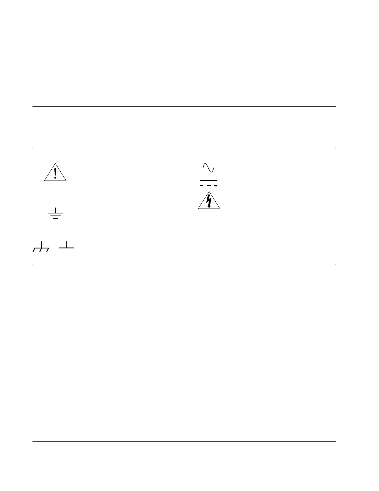
Safety Symbols
Instruction manual symbol affix ed to
Instruction manual symbol affix ed to
product . Ind ica te s t hat t he u ser must r efer t o
product . Ind ica te s t hat t he u ser must r efer t o
the manu a l fo r sp ec ific WAR N IN G or
the manu a l fo r sp ec ific WAR N IN G or
CAUTION information to avoid personal
CAUTION information to avoid personal
injury or dam age to the product.
injury or dam age to the product.
Indicates the field wi ring terminal t hat must
be connect ed to earth ground before
operating the equipment—protects against
electrical shock in case of fault.
WARNING
Alternating current (AC)
Direct current (DC).
Indicates hazardous voltages.
Calls attention to a procedure, practice, or
condition that could cause bodily injury or
death.
or
Frame or c hassis grou nd termina l—typicall y
connect s to the equipm ent's metal frame.
CAUTION
Calls attention to a procedure, practice, or
condition that could po ssibly c ause damage to
equipment or permanent loss of data.
WARNINGS
The follo w ing general safety precautions mus t be observed during all phases of operation, service, and re pair of this product. F a ilu re to
comply with these precautions or with specific warnings elsewhere in this manual violates safety standards of design, manufacture, and
intended use of the product. Agilent Technologies, Inc. assumes no liab ility for the customer's failure to comply with these requirements.
Ground the equipm ent: For Safety Class 1 equipment (equipment having a protective earth terminal), an uninterruptible safety earth
ground must be provided from the mains pow er source to the product input wiring term inals or suppl ied power cable.
DO NOT operate the produc t in an explosive atmosphere or in the pr esence of flammable gase s or fumes.
For cont inued protection against fire, replace the li ne fuse(s) only with fuse(s) of the same voltage and current rating and type. DO NOT
use repaired fuse s or short-circuited fuse holders.
Keep away from live circuits: Ope rating personnel mus t not remove equipment covers or shields . Procedures involving the removal of
covers or shields are for use by serv ice-trained personn el only. Under certain conditions, dangerous voltages may exi st even with the
equipmen t sw itch ed off. To a void d ang er ous elect r ical sho ck, DO NOT per form proc edu re s invo lv ing co ver or shie ld rem oval u nl ess you
are qualified to do so.
DO NOT operat e damaged equipment: Whenever it is possible that the safety protection features built into this product have been
impaired, either through physical damage, e x cessive moisture, or any other reason, REMOVE POWER an d do not use the product until
safe operat i on ca n be veri fi ed by servi ce- trai ne d person nel . If ne ces sa ry, re tu rn the pr odu ct to an Agi lent Tech nologi es Sales and Servi ce
Office for service and repair to ensure that safety features are ma intained.
DO NOT serv ice or adj ust al one : Do not at t empt in te rnal ser vi ce or adj us tmen t u nl ess an oth er per son , cap abl e o f rend er in g fi rst ai d an d
resuscitation, is present.
DO NOT substitut e parts or modify e quipm ent: Be cause of the da nger of intr od ucing a ddi tion al hazar ds, do not in st all s ubsti t ute pa rt s
or perform any unauthori zed modification to the product. Return the product to an Agilent Tec hnologies Sales and Service Office fo r
service and repair to ensure that safety features are mai ntained.
8
Page 9

DECLARATION OF CONFORMITY
According to ISO/IEC Guide 22 and CEN/CENELEC EN 45014
Manufacturer’s Name:
Agilent Technologies, Incorporated
Manufacturer’s Address: Measurement Product Generation Unit
815 14th ST. S.W.
Loveland, CO 80537 USA
Declares, that the product
Product Name:
Model Number:
Arbitrary Waveform Generator
E1441A
Product Options: This declaration covers all options of the above product(s).
Conforms with the following European Directives:
The product herewith complies with the requirements of the Low Voltage Directive 73/23/EEC and the EMC Directive 89/336/EEC
and carries the CE Marking accordingly
Conforms with the following product standards:
EMC Standard
IEC 61326-1:1997+A1:1998 / EN 61326-1:1997+A1:1998
CISPR 11:1997 +A1:1997 / EN 55011:1998
IEC 61000-4-2:1995+A1:1998 / EN 61000-4-2:1995
IEC 61000-4-3:1995 / EN 61000-4-3:1995
IEC 61000-4-4:1995 / EN 61000-4-4:1995
IEC 61000-4-5:1995 / EN 61000-4-5:1995
IEC 61000-4-6:1996 / EN 61000-4-6:1996
IEC 61000-4-11:1994 / EN 61000-4-11:1994
Limit
Group 1 Class A
4kV CD, 8kV AD
3 V/m, 80-1000 MHz
0.5kV signal lines, 1kV power lines
0.5 kV line-line, 1 kV line-ground
3V, 0.15-80 MHz
I cycle, 100%
[1]
Canada: ICES-001:1998
Australia/New Zealand: AS/NZS 2064.1
Safety
IEC 61010-1:1990+A1:1992+A2:1995 / EN 61010-1:1993+A2:1995
Canada: CSA C22.2 No. 1010.1:1992
UL 3111-1:1994
Supplemental Information:
[1]
The product was tested in a typical configuration with Agilent Technologies test systems.
September 5, 2000
Date Name
Quality Manager
Title
Authorized EU-representative: Agilent Technologies Deutschland GmbH, Herrenberger Straβe 130, D 71034 Böblingen, Germany
For further information, please contact your local Agilent Technologies sales office, agent or distributor.
9
Page 10

Notes:
10
Page 11

Notes:
11
Page 12

Notes:
12
Page 13
Function/Arbitrary Waveform Generator
General Information
This chapter provides ge neral modul e informati on followed by the t asks you
must perform to set up your module and verify your installation was
successful. Chapter cont ents are:
Chapter 1
Agilent E1441A
Module Setup
• Setting the Module Address Switch . . . . . . . . . . . . . . . . . . . . page 14
• Interrupt Priority . . . . . . . . . . . . . . . . . . . . . . . . . . . . . . . . . . . page 15
• Installing into the Mainframe . . . . . . . . . . . . . . . . . . . . . . . . . page 15
• Faceplate Indicators and Connectors . . . . . . . . . . . . . . . . . . . page 16
• Initial Operation . . . . . . . . . . . . . . . . . . . . . . . . . . . . . . . . . . . page 17
• The Agilent E1441A Function Generator and Arbitrary Waveform
Generator (FUNC/ARB WAVEFORM GEN) is a VXIbus C-size
message-based sla ve device.
• Programming the Agilent E1441A can either be through a command
module using an GPIB interface or an embedded controller. In either
case you can use the Standard Commands fo r Programmable
Instruments (SCPI; See “Agilent E1441A SCPI Command Ref erence”
on page 65.) with the Standard Instrument Control Language (SICL).
• A VXIplug&play driver is supplied on a CD Rom with the Agilent
E1441A. All documentation for the use of this driver is contained
on-line.
• Option 001 provides a ±1 ppm timebase which gives 10 times the
frequency stabil ity of the standard timebase. It also provides you the
ability to control phas e offset.
Chapter 1
Agilent E1441A Function/Arbitrary Waveform Generator Module Setup 13
Page 14
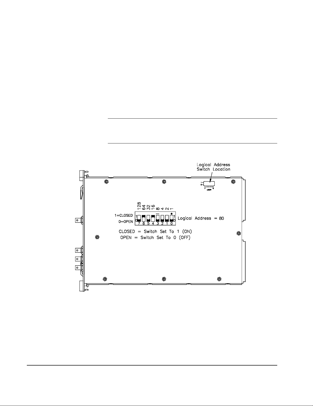
Setting the Module Address Switch
The logical addre ss switch factory setting is 80. Valid addre sses are from 1
to 254 for static configura tion (the address you set on the switch) and
address 255 for dynamic configuration. The Agilent E1441A supports
dynamic configuration of the addr ess. This means the address is set
program- matically by the resource manager when it encounters a module
with address 255 that supports dyna mic configuration.
If you install more than one Function Generator, each module must have a
different logic al address. If you use a VXIbus command module, the logical
address must be a multiple of eight (e.g., 80, 88, 96, etc.) Each instrument
must have a unique secondary addres s which is the logic al address divided
by eight.
Note When using an Agilent E1405A/B or E1406A as the VXIbus resource
manager with SCPI commands, the F unction Generator's address switch
value must be a multiple of 8.
Figure 1-1. Setting the Logical Address
14 Agilent E1441A Function/Arbitrary Waveform Generator Module Setup
Chapter 1
Page 15

Interrupt Priority
The Agilent E1441A Function Generat or / Arbitrary Waveform Generator
is a VXIbus interrupter. However, ther e is no interrupt priority level se ttin g
to be made on the module. Interrupt priority level, setup and activation are
configured on the resource manager . Fo r example, you configure the
interrupt priority on the Agilent E1405B and E1406A Command Modules
using the DIAGnostic:INTer rupt command subsystem. Refer to your
resource manager's docume ntation for infor mation on setti ng your system's
interrupt priority.
Installing into the Mainframe
The Agilent E1441A should always be installed to the right of an existing
VXIbus module with no e mpty slots betwe en them. The sof t black gasket on
the Agilent E1441A’s left panel must conta ct an adjacent mo dule in order to
provide the module’s speci fied Electromagnetic Compatibility (EMC).
WARNING To prevent electical shock in the case of equipment or field
wiring failure, tighten the faceplate (module retaining) screws.
Chapter 1
Agilent E1441A Function/Arbitrary Waveform Generator Module Setup 15
Page 16
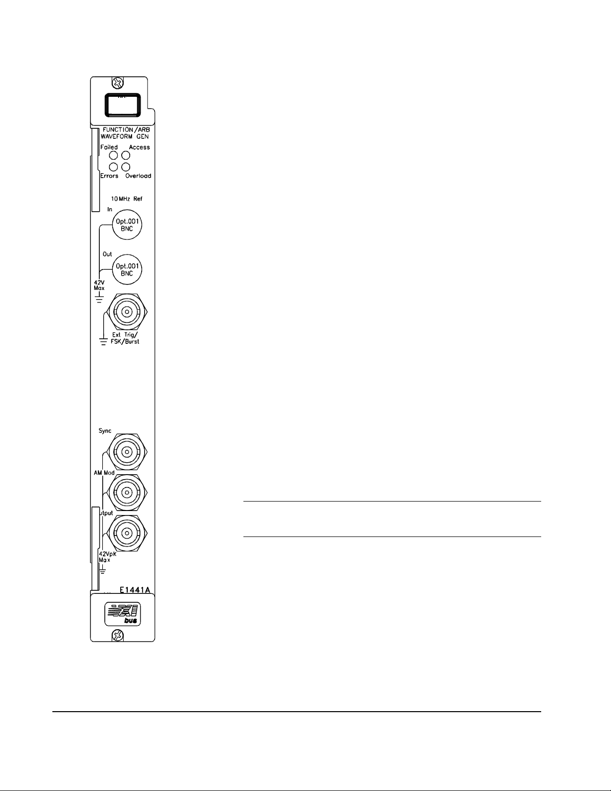
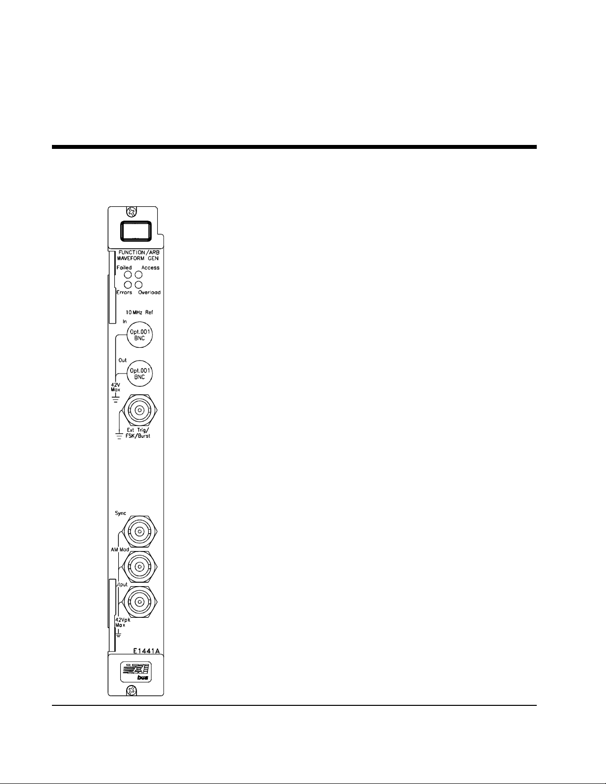
Faceplate Indicators and Connec tors
Faceplate Indicators
"Failed" turns on momentarily during the function generator's power-on
self-test. If the function generator successfully establishes internal
communication, the indicator turns off. If the function generator fails to
establish inter nal communication, the indicat or remai ns on.
"Access" turns on only when the res ource manager is communicating with the
function generator.
"Errors" turns on only when an error is present in the function generator's
error queue. The error can result from improperly exe cuting a command or the
function generato r being unable to pass a part of self-test or calibration. Use
the SYST:ERR? command repeatedly to cl ear the error que ue. A response of
+0,"No error" indicate s the error queue is empty. See Appendix B, Agilent
E1441A Function Generator Error Messages, for a list of all errors.
"Overload" tu rns on whe n the func tion gener ator sense s a si gnal appl ied to t he
output terminal that exce eds the present output level. The output terminal is
disconnected while the "Overloa d" light is on.
Option 00 1 Phase-Lo ck 10 MH z Reference Terminal s
These connectors allow sync hronization between multiple Agilent E1441As
or to an external 10 MHz clock signa l. Additi onally, opti on 001 allows p hase
offset control.
Standard Input/Output Terminals
The function generator 's faceplate contains the foll owing terminals:
1. External Trigger/FSK/Burst modulation input terminal
2. Sync signal output terminal for all standard output functi ons
3. AM Modulation input terminal
4. Output terminal
Note The outer shell of the "Ext T rig/FSK/Burst" BNC connect or is
connected to chassis. All other BNC connectors are floating.
Figure 1-2. F unction Gene ra tor Terminals
16 Agilent E1441A Function/Arbitrary Waveform Generator Module Setup
Chapter 1
Page 17

Initial Operation
Note This discussion applies only to SCPI (Standard Commands for
To program the Function Generator using SCPI, you must select the
interface address and SCPI commands to be used. Guidelines to sele ct SCPI
commands for the Functi on Genera tor f ollow. See the Agilent 7 5000 S eries
C Installation and Getting Started Guide for interface addressing.
Programmable Instr uments) programming. The program is written using
Agilent VISA function calls. Agilent VISA allows you to execute on
VXIplug&play system frameworks tha t have the VISA I/O layer installed
(visa.h includ e fi le).
Programming the
Function Generator
#include <stdio.h>
#include <visa.h>
/*** FUNCTION PROTOTYPE ***/
void err_handler (ViSession vi, ViStatus x);
#define DEVICE_ADDRESS "GPIB0::9::10::INSTR"
void main(void)
{
char buf[512] = {0};
Example: Perform a Fun ction Generator Self -Test and Read the Result.
Programming the F unction Generator using Standard Commands for
Programmable Instrumen ts (SCPI) requires that you select the contr oller
language (e.g., C, C++, Basic, etc.), inte rface address and SCPI commands
to be used. See the "C-Size Installa tion and Getting Started Guide" (or
equivalent) for int erfacing, addressing and controller information.
The following C program verifies c ommunication between the controller,
mainframe and Func tion Generator . It res ets the module ( *RST), queri es the
identity of the module (*IDN?) and initiates a self-test of the Function
Generator. See the program 1441init.c on the Instrument Drivers CD.
Chapter 1
#if defined(_BORLANDC_) && !defined(_WIN32_)
_InitEasyWin();
#endif
ViStatus err;
ViSession defaultRM, funcgen;
/* Open resource manager and Function Generator sessions*/
viOpenDefaultRM (&defaultRM);
viOpen(defaultRM, DEVICE_ADDRESS,VI_NULL, VI_NULL, &funcgen);
/* Set the timeout value to 10 seconds. */
viSetAttribute(funcgen, VI_ATTR_TMO_VALUE, 10000);
Agilent E1441A Function/Arbitrary Waveform Generator Module Setup 17
Page 18

/* Reset the module, and clear status regs. */
err=viPrintf(funcgen, "*RST;*CLS\n");
if(err != VI_SUCCESS) err_handler(funcgen, err);
/* Query the module identification. */
err=viPrintf(funcgen, "*IDN?\n");
if(err != VI_SUCCESS) err_handler(funcgen, err);
err=viScanf(funcgen, "%t", &buf);
if(err != VI_SUCCESS) err_handler(funcgen, err);
printf("Module ID = %s\n\n", buf);
/* Perform a module self-test. */
err=viQueryf(funcgen, "*TST?\n", "%t", &buf);
if(err != VI_SUCCESS) err_handler(funcgen, err);
printf("Self-test response (0 passed) = %s\n\n", buf);
/* Check for system errors. */
err=viQueryf(funcgen, "syst:err?\n", "%t", buf);
if(err != VI_SUCCESS) err_handler(funcgen, err);
printf("System error response = %s\n\n", buf);
/* Close Instrument Session */
err=viClose(funcgen);
if(err != VI_SUCCESS) err_handler(funcgen, err);
} /* end of main */
/*** Error handling function ***/
void err_handler(ViSession funcgen, ViStatus err)
{
char buf[1024] = {0};
viStatusDesc(funcgen, err, buf);
printf("ERROR = %s\n", buf);
return;
}
Example Pro grams Several exampl e progr ams, including a performance verification program
and an adjustment program, can be found on the Agilent Universal
Instrument Drivers CD. The directory path is <drive>:\examples\hpe1441.
18 Agilent E1441A Function/Arbitrary Waveform Generator Module Setup
Chapter 1
Page 19

Agilent E1441A Application Information
This chapter provides information for using the Agilent E1441A Function /
Arbitrary Waveform Generator in se ven parts:
• Functional Capabilities . . . . . . . . . . . . . . . . . . . . . . . . . . . . . . page 19
• Phase-Lock Capabilities (Opt 001) . . . . . . . . . . . . . . . . . . . . . page 49
• Triggering the Function Generator . . . . . . . . . . . . . . . . . . . . . page 52
• System-Related Operations. . . . . . . . . . . . . . . . . . . . . . . . . . . page 55
• Power-On and Reset State. . . . . . . . . . . . . . . . . . . . . . . . . . . . page 57
• Application Program Examples . . . . . . . . . . . . . . . . . . . . . . . page 58
Functional Capabilities
This section provides detailed information about the functional capabili ties
of the function generator. This section is divided into the following topic s:
Chapter 2
• “ Output Configuration” on page 19
• “Amplitude Modulation (AM)” on page 28
• “ F requency Modulation (FM)” on page 30
• “Burst Modulation” on page 33
• “Frequency-Shift Keying (FSK) Modulation” on page 40
• “ F requency Sweep” on page 43
• “ Arbitrary Wa veforms” on page 46
See also“Command Index by Function” on page 65.
Chapter 3, Agilent E1441A SCPI Command Reference, lists the syntax for
the
SCPI commands available to program the funct ion generator.
Throughout this manual, the following conventions are used for
SCPI command syntax for remote interfac e programming.
Square brackets ( [ ] ) indicate optional keywords or parameters.
Triangle brackets ( < > ) indicate that you must substitute a value for the
enclosed parameter.
A vertical bar ( | ) separates multiple paramete r choices.
Chapter 2
Output
Configuration
This section contains information to help you configure the function
generator for o utputting wave forms. You may never have to change some of
the parameters discusse d here , but the y are provided to give you the
flexibilit y you might need. Topics covered on output configuration are:
Agilent E1441A Application Information 19
Page 20

• Output Function
• Output Frequency
• Output Amplitude
• DC Offset Voltage
• Output Units
• Duty Cycle
• Output Termination
• SYNC Signal
• Instrument Storage State
Note The Agilent E1441A functions do not all have the same maxi mum limit for
frequency and amplitude. Therefore, when c hanging functions, you can
generate a "Settings conflict" error when the new function's frequency or
amplitude has a maximum value less than the current output setting. The
function generato r automatically adjusts to the maximum value of the
function you specify and generates the new output signa l.
Output Function The function generator can output five standard waveforms including sine,
square, tria ngle, ramp, and n oise. You can also se lect on e o f five predefine d
arbitrary waveforms or download your own custom waveforms. You can
internally modulate any of the standard waveforms (including arbitrary)
using
AM, FM, FSK, or burst modulation. Linear or logarit hmic frequency
sweeping is available for any of the standard wavef orms (excep t noise) and
arbitrary wav ef o rms. The default function is sine wave.
Possible Conflict wit h Output Frequency: The output frequency is
automatically adj usted if you select a function whose maximum frequency
is less than that of the currently active function. For example, if you output
a 1 MHz sine wave and then change the function to triangle wave, the
function generato r will adjust the output to 100 kHz (the upper limit for
triangle waves). See Table 2-1. A -221, “Settings conflict” error is
generated and the frequency is adjusted.
Possible Conflict wit h Output Amplitude: The output amplitude is
automatically adj usted if you select a function whose maximum amplitude
is less than that of the currently active function. This confli ct may arise when
the output units a re Vrms or dBm due t o th e dif fer enc es i n cr est f act or for t he
output functions . For example, if you outpu t a 5 Vrms squar e wave (into 50
ohms) and then change the f unction to s ine wave, t he function generator wil l
adjust the output a mplitude to 3. 535 Vrms (the upper li mit for sine wave s in
Vrms). See Table 2-4. A -221, “Settings conflict” e rror is gene rated and the
amplitude is adjusted.
Valid Function/ Modulation Modes
The following matrix shows whic h output functions are allowed with each
modulation mode. Each “
a function that is not allowed with the selected modulati on, the modulation
mode is turned off
X” indicates a valid combina tion. I f you change to
20 Agilent E1441A Application Information
Chapter 2
Page 21

.
Table 2-1.
Sine Square Triangle Ramp Noise Arb
AM Carrier X X X X X
AM Modulating Wave X X X X X X
FM Carrier X X X X X
FM Modulating Wave X X X X X X
FSK Modulation X X X X X
Burst Modulation X X X X X
Frequency Sweep X X X X X
Use the following command to select the output function:
FUNCtion:SHAPe SIN|SQU|TRI|RAMP|NOIS|USER|DC
You can also use the APPLy command to select the function, frequency,
amplitude, and offset with a single command. Because the APPLy command
also changes duty cycle, modulation type, trigger source, and trigger slope,
you must place the APPLy command fir st in any sequence of configur ation
commands.
Output Frequency As shown below, the output frequency range depends on the function
currently selecte d. The table shows functions in decending order of the
maximum frequency. The default frequency is 1 kHz for all functions.
Table 2-2.
Parameter
Name
frequency numeric Sine 100 µHz 15 MHz Hz
Parameter
Type Function
Square 100 µHz 15 MHz Hz
Built-In Arbs 100 µHz 5 MHz Hz
Ramp 100 µHz 100 kHz Hz
Triangle 100 µHz 100 kHz Hz
Minimum
Frequency
Maximum
Frequency
Default
Units
Chapter 2
Agilent E1441A Application Information 21
Page 22

For arbitrary waveforms that you create and download to memory,
the maximum frequency depends on the number of points specified in the
waveform. As shown below, the maximum output frequency decreases as
you specify more points in the waveform. The five built-in arbitrary
waveforms can be output at a maximum of 5 MHz.
Table 2-3.
Number of Arb Poi nts Minimum Frequency Maximum Frequency
8 to 8,192 (8k) 100 mHz 5 MHz
8,193 to 12, 287 (12k) 100 mHz 2.5 MHz
12,288 to 16,000 100 mHz 200 kHz
Possible Conflict wit h Function Change: The output frequency is
automatically adj usted if you select a function whose maximum frequency
is less than that of the currently active function. For example, if you output
a 1 MHz sine wave and then change the function to triangle wave, the
function generato r will adjust the output to 100 kHz (the upper limit for
triangle waves). A -221, “Sett ings conflict” error is generated and the
frequency is adjusted.
Possible Conflict wit h Duty Cycle (square wave only): For output
frequencies above 5 MHz, the duty cycle is limited to values between 40%
and 60% (below 5 MHz, the range is 20% to 80%). The duty cycle is
automatically adj usted if you select a frequency that is not valid wit h the
present duty c ycle. For example, if you set the duty cycle to 70% and then
change the frequency to 8 MHz, the function gener ator will automatically
adjust the duty cycle to 60% (the upper limit for this frequency). A -221,
“Settings conflict” error is generated and the duty cycle is adjusted.
Use the following command to set the output frequenc y:
FREQuency <frequency>|MINimum|MAXimum
You can also use the APPLy command to select the function, frequency,
amplitude, and offset with a single command. Because the APPLy command
also changes duty cycle, modulation type, trigger source, and trigger slope,
you must place the APPLy command fir st in any sequence of configur ation
commands.
Output Amplitude As shown below, the output amplitude range depends on the function
currently selecte d and the output termination. The default amplitude is
100 mVpp (into 50 ohms) for all functions.
22 Agilent E1441A Application Information
Chapter 2
Page 23

Table 2-4.
Parameter
Name
amplitude numeric Sine 50Ω 50 mVpp 10 Vpp Vpp
amplitude numeric Sine Open Circuit 100 mVpp 20 Vpp Vpp
Parameter
Type Function
Square 50Ω 50 mVpp 10 Vpp
Triangle 50Ω 50 mVpp 10 Vpp
Ramp 50Ω 50 mVpp 10 Vpp
Noise 50Ω 50 mVpp 10 Vpp
Built-In
Arbs
Square Open Circuit 100 mVpp 20 Vpp
Triangl e Open Circuit 100 mVpp 20 Vpp
Ramp Open Circui t 100 mVpp 20 Vpp
Noise Open Circuit 100 mVpp 20 Vpp
Built-In
Arbs
Output
Termination
50Ω 50 mVpp 10 Vpp
Open Circuit 100 mVpp 20 Vpp
Minimum
Amplitude
Maximum
Amplitude
Default
Units
For arbitrary waveforms, the maximum amplitude will be limited if the data
points do not span the full range of the outpu t
Converter). For example, the bui lt-in “
range of values between
±1 and therefore its maximum amplitude is 6.084
SINC” waveform does not u se the full
DAC (Digital- to-Analog
Vpp (into 50 ohms).
Chapter 2
Possible Conflict wit h Function Change: The output amplitude is
automatically adj usted if you select a function whose maximum amplitude
is less than that of the currently active function. This confli ct may arise when
the output units a re Vrms or dBm due t o th e dif fer en ces i n cr est f act or for t he
output functions . For example, if you outpu t a 5 Vrms squar e wave (into 50
ohms) and then change the f unction to s ine wave, t he function generator wil l
adjust the output a mplitude to 3. 535 Vrms (the upper li mit for sine wave s in
Vrms). A -221, “Settings conflict” error is generated and the amplitude is
adjusted.
Output Amplitude and Output Termination: The output amplitude is
automatically adj usted (and no error is generated) if you change the output
termination. For example, if you set the amplitude to 10 Vpp and then
change the terminatio n from 50 ohms to “high impedance”, the displayed
amplitude will double to 20 Vpp. If you change from “high impedance” to
50 ohms, the displayed amplitude will drop in half. See “Output
Termination” on page 25. for more information.
Offset Voltage Restrictions: The output amplitude (in Vpp) and the
dc offset voltage must obey the foll owing restrictions. If the specified
amplitude is not va lid, the function generator will automatically adjust it to
Agilent E1441A Application Information 23
Page 24

the max im u m v alu e al l ow ed wi t h t h e pr ese n t of fs et v ol t ag e. ( Vmax is either
V
V
10 volts for a high impedance terminat ion or 5 volts for a 50 ohm
termination; Vpp is the output amplitude in volts peak-to-peak.)
pp
--------
V
offset
+ V
≤ and V
2
max
offset
2V
≤
pp
A -221, “Settings conflict” error is generated and the amplitude is adjusted.
A momentary glitch occurs in the output waveform at certain voltages due
to output attenuator switching. This positive-going glitch occurs when the
output voltage crosses t he break-point voltage either from a lower vo ltage or
a higher volta ge. The voltages are shown below (inVpp) for a 0 volt dc
offset: .252, .399, .502, .796, 1, 1.59, 2.0, 3.17, 3.99, 6.32, 7.96
The output voltage will momentarily drop to 0 volts at certain voltages due
to output relay switchin g. This oc curs when the output voltage crosses the
break-point voltage either from a lower voltage or a higher voltage. The
voltages are shown below (in Vpp) for a 0 volt dc offset:
.317, .632, 1.26, 2.52, 5.02
You can set the units for output amplitu de to Vpp, Vrms, or dBm. See
“Output Units” on page 25. for more information.
For dc volts, the output level is actually controlled by setting the offset
voltage. You can set the dc voltage to any value bet ween
50 ohms or
±10 Vdc into an open circuit. See “DC Offset Voltage” on
±5 Vdc into
page 24. for more information.
Use the following command to set the output amplitude:
VOLTage <amplitude>|MINimum|MAXimum
You can also use the APPLy command to select the function, frequency,
amplitude, and offset with a single command. Because the APPLy command
also changes duty cycle, modulation type, trigger source, and trigger slope,
you must place the APPLy command fir st in any sequence of configur ation
commands.
DC Offset Voltage At power-on, the dc offse t is set to 0 volts. You can set the offset to a positive
or negative number with the r estriction s shown below. If the specified offset
voltage is not val id, the func tion ge nerato r will automati call y adjust it to the
maximum dc volta ge allowed with the pr esent amplitu de. (Vmax is e ither 10
volts for a high impedance termination or 5 volts for a 50 ohm termination;
Vpp is the output amplitude in volts peak-t o-peak.)
pp
V
offset
A -221, “Settings conflict ” error is generated and the o ffset is adjus t ed.
DC Offset and Output Termination: The offset voltage is automatically
adjusted (and no error is generated) if you change the output terminatio n.
For example, if you set the offset to 100 mVdc and then change the
--------
+ V
≤ and V
2
max
offset
2V
≤
pp
24 Agilent E1441A Application Information
Chapter 2
Page 25

terminatio n fro m 50 o h ms to “h ig h imp edance”, the displ ay ed o ffs et will
double to 200 mVdc. If you chang e from “hi gh impedanc e” t o 50 ohms, the
displayed off set will drop in h alf. See “Output T erminati on” on page 25. for
more information.
For dc volts, the output level is actually controlled by setting the offset
voltage. You can set the dc voltage to any value bet ween
50 ohms or
±10 Vdc into an open circuit.
±5 Vdc into
Use the following command to set the dc offset:
VOLTage:OFFSet <offset>|MINimum|MAXimum
You can also use the APPLy command to select the function, frequency,
amplitude, and offset with a single command. Because the APPLy
command also changes duty cycle, modulation type, trigger source, and
trigger slope , you m ust place the APPLy command fi rst in any sequence of
configuration commands.
Output Units Applies only to output amplitude (does not affect offset). At power-on,
the units for output amplitude are volts peak-to-peak.
Output units:
Vpp, Vrms, or dB m . The default is Vpp.
The unit set ting is stor ed in volatile memory; the units are set to “Vpp” when
power has been off or after a remote interface reset.
Use the following command to select the units of the output signal:
VOLTage:UNIT VPP|VRMS|DBM|DEFault
Output Termination Applies only to output amplitude and offset voltage. The function generator
has a fixed output i mpedance of 50 ohms on the OUTPUT terminal. You can
specify whether you ar e terminating the output into a 50 ohm load or an open
circuit. Incorrect impedance matching between the funct ion generator and
your load will result in an amplitude or off set which does not match the
specified signal le vel.
Output terminat ion: 50
2-4 for a list of amplitude limits for all functions.
The output termi nation setting is stored in volatile memory; 50
when power has been off or after a remote interface reset.
The amplitude (or dc offset) is automatically adjusted (and no error is
generated) if you c hange the out put termin ation. For example , if you set th e
amplitude to 10 Vpp and then change t he terminati on from 50 ohms to “high
impedance”, the ampl itude will double t o 20 Vpp. If you change from “high
impedance” to 50 ohms, the amplitude will drop in half.
Ω or High impedanc e. The default is 50Ω. See Table
Ω is selected
Chapter 2
If you specify a 50 ohm termination but are actually terminati ng into an open
circuit, the output will be twice the value specified. For example, if you se t
the offset to 100 mVdc (and specify a 50 ohm termination) but do not
connect a 50 Ω load, the actual offset will be 200 mVdc.
Agilent E1441A Application Information 25
Page 26
Use the following command to set the output termination:
OUTPut:LOAD 50|INFinity|MINimum|MAXimum
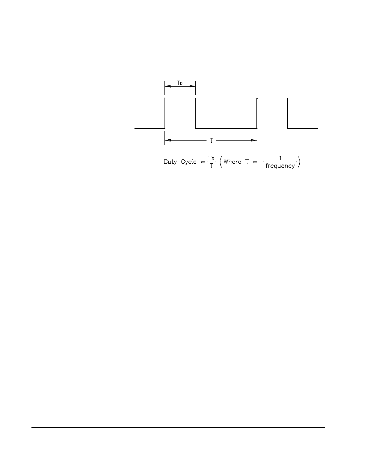
Duty Cycle Applies only to square waves. Duty cycle is specified as a percen t age an d
represents the amount of time per cycle tha t the square wave is high.
Figure 2-1.
Duty cycle: 20% to 80%, in 1% increments (frequency ≤5 MHz).
40% to 60%, in 1% increments (frequency > 5 MHz).
The default is 50%.
The duty cycle is stored in volatile memory; the duty cycle is set to 50%
when power has been off or after a remote interface reset. The APPLy
command automatically sets the duty cycle to 50% for square waves.
Before attempting to set the duty cycle , you must enable the square wave
function. No error is generated, but the specif ied duty cycl e is remembered
when you change to the square wave function.
The duty cycle setting is remember ed when you change from square wave
to another function. When you return to the square wave function, the
previous duty cycle is use d.
Possible Conflict wit h Output Frequency: The duty cycle is automati cally
adjusted if you select a frequency that is not valid with the present duty
cycle. For example, if you set the duty cycle to 70% and then change the
frequency to 8 MHz, the function generator will automatically adjust the
duty cycle to 60% (the upper limit for this frequency).
Use the following command to set the duty cycle:
PULSe:DCYCle <percent>|MINimum|MAXimum
The APPLy command automatically sets the duty cycle to 50% for square
waves.
Sync Signal A sync signal output is provided on the front- panel Sync terminal.
All of the standard output functions ( except dc and noise) have an associated
sync signal. For certain applications where you may not want to output the
26 Agilent E1441A Application Information
Chapter 2
Page 27

sync signal, you can disable the Sync terminal.
By default, the sync signal is routed to the Sync terminal (enab le d).
When the sync signal is disabled, the output level on the Sync terminal is
indeterminate (it mi ght be a
TTL “high” or a TTL “low”).
For sine, square, triangle, and ramp waveforms, the sync signal is a
TTL
“high” when the waveform's output is posit ive, relativ e to zero volts (or the
dc offset value). The signal is a
TTL “low” when the output is negative,
relative to zero volts ( or the dc offset value).
For arbitrary waveforms, a momentary
TTL “high” pul se (> 200 ns) is output
which corresponds to the fir st downloaded point in the waveform.
For AM and FM, the sync signal is referenced to the modulating signa l (not
the carrier). A momentary
TTL “high” pulse (> 200 ns) is output a t each
zero-crossing point of the modulating signal.
For the counted burst mode, a
TTL “low” signal is output while the specif ied
number of cyc les i s ou tput ( for the du ration of the burst ). Af ter the specif ied
number of cycles ha s been out put, the sync si gna l goes “high ” u ntil the next
burst.
For the external gated burst mode , the sync signal is a
TTL “high” when the
output is positi ve, relative to zero volts (or the dc offset value). The signal is
a
TTL “low” when the output is negative, relative to zero volts (or the dc
offset value).
For FSK, a momentary
TTL “high” pulse (> 200 ns) is output on the
transition to the “hop” fre quency.
For frequency sweeps, the sync signa l is a
(when the start frequenc y is output) and is a
TTL “low” at the start of the sweep
TTL “high” at the end of the
sweep (when the stop frequency is output).
Use the following command to set the SYNC signal mode:
OUTPut:SYNC OFF|ON
Setting is s tored in volatile
memory.
Instrument State Storage You can store up to four different instrument states in non-volatil e memory.
This enables you to recall the entire instrument configuration using the
*RCL common command.
Four memory locations (numbered 0, 1, 2, and 3) are available to store
instrument configurations. The state storage feature “remembers” the
function (includi ng arbitrary waveforms), frequenc y, a mplitude, dc offset,
duty cycle, as well as any modulation parameters. To recall a stored state,
you must use the same memory location used previously to store the state.
The instrument state in memory loca tion 0 can become the "*RST" or
power-up state by setting MEMory:STATe:RECall:AUTO ON. See
reference for this command on page 85
You cannot recall the instr ument stat e from a memory locati on that was not
Chapter 2
Agilent E1441A Application Information 27
Page 28

previously specifie d as a storage location. For example, an error is gener ated
if you attempt to recall from memory loc ation “2” but have never stored to
that location.
A +810, “State has not been stored” error is generated if nothing is stored
in the specified memory location.
Amplitude
Modulation (AM)
Any arbitrary waveforms downl oaded to “
remembered. However, if an arbi tr ary waveform is being output from
non-volatile memory when the state is stor ed, the wavefor m data is stored.
The stored waveform is output when the instrument state is recalled.
If you delete an ar bitrary waveform after stor ing the state, the wave form data
is lost and the function gene rator will output the “
of the deleted waveform when the state is recalled.
Use the following commands to save and recall state s:
*SAV 0|1|2|3
*RCL 0|1|2|3
You can delete individual stored sta tes and clear the memory location. If
nothing is stored in the specif ied memory location, a +810, “State has not
been stored” error is generated. Do not delete state 0 or an error +772 will
be generated. See “772” on page 148.
MEMory:STATe:DELete 0|1|2|3
A modulated waveform consists of a carrier waveform and a modulating
waveform. In
the modulating waveform. The function generator will accept an inter nal
modulating signal, an external modulating signal, or both. Topics c overed
on amplitude modulation are:
AM, the amplitude of the carrie r is varied by the amplitude of
VOLATILE” memo ry are not
SINC” waveform in place
• AM Carrier Waveform Shape
• AM Carrier Frequency
• Amplitude Modulating Waveform Shape
• Amplitude Modulating Waveform Frequency
• Amplitude Modulation Depth
• Amplitude Modulating Source
Only one modulation mode can be enabled at a time. When you e nable
the previous modulation mode is tur ned off.
Use the following command to select AM modulation: To ensure proper
operation, you s hould ena ble
parameters.
AM:STATe OFF|ON
AM Carrier Waveform
Shape
28 Agilent E1441A Application Information
AM carrier shape: Sine , Square, Triangle, Ramp, or Arbitrary waveform.
The default is Sine.
AM,
AM after you have set up t he othe r modul ation
Chapter 2
Page 29

You cannot use the noise function or dc volts as the AM carrier waveform.
Use the following command to select the shape of the output function:
FUNCtion:SHAPe SINusoid|SQUare|TRIangle|RAMP|USER|DC
You can also use the APPLy command to select the function, frequency,
amplitude, and offset with a single command. Because the APPLy command
also changes duty cycle, modulation type, trigger source, and trigger slope,
you must place the APPLy command fir st in any sequence of configur ation
commands.
AM Carrier Frequency Carrier frequency: 100 µHz to 15 MHz (100 kHz for triangle and ramp).
The default is 1 kHz.
For arbitrary waveforms, the maximum carrier frequency depends on the
number of points specified in the waveform. The five built-in arbitrary
waveforms can be output at a maximum of 5 MHz.
Use the following command to set the carrie r fre quency:
FREQuency <frequency>|MINimum|MAXimum
Amplitude Modulating
Waveform Shape
Amplitude Modulating
Waveform Frequency
The function gener ator will accept an inter nal modulating signal, a n external
modulating signal, or both.
Modulating waveform shape (internal source): Sine, Square, Triangle,
Ramp, Noise, or Arbitrary wavefor m. The defau lt is Sine.
You can use the noise function as the modulating wavefor m. However, you
cannot use the noise function or dc volts as the carrier waveform.
Use the following command to set the modulat ing waveform shape:
AM:INTernal:FUNCtion SIN|SQU|TRI|RAMP|NOIS|USER
The function generator will accept an internal modulating signa l, an external
modulating signal, or both.
Modulating fr equency (i nte rnal sour ce): 10 mHz to 20 kHz. The default is
100 Hz.
The sync signal for
carrier). A momentary
AM is referenced to the modulating signa l (not the
TTL “high” pulse (> 200 ns) is output at each
zero-crossing point of the modulating signal. The signal is output from the
front-panel SYNC terminal.
Use the following command to set the modulat ing waveform frequency:
Amplitude Modulation
Chapter 2
Depth
AM:INTernal:FREQuency <frequency>|MINimum|MAXimum
The modulat ion depth is expres sed as a percentage and repr esents the extent
of the amplitude variati on. At 0% modulation, the output amplitude is half
of the selected value. At 100% modulation, the output amplit ude equals the
selected val ue.
Agilent E1441A Application Information 29
Page 30
Modulation depth: 0% to 120%. The default is 100%.
Use the following command to set the modulat ion depth:
AM:DEPTh <depth in percent>|MINimum|MAXimum
Amplitude Modulating
Source
The function generator will accept an internal modulating signa l, an external
modulating signal, or both.
Modulating s ource: Internal- External (both) or External only. The default
is Both (inte rnal-external).
The External modulating sourc e is always enabled.
When both sources are enabled (internal-external), the function generator
adds the internal and externa l modulating signals (the carrier waveform is
actually modulated with two waveforms).
When the internal source is disabled (external only), the carrier waveform is
expecting a modulating sig nal on the AM Modulation terminal.
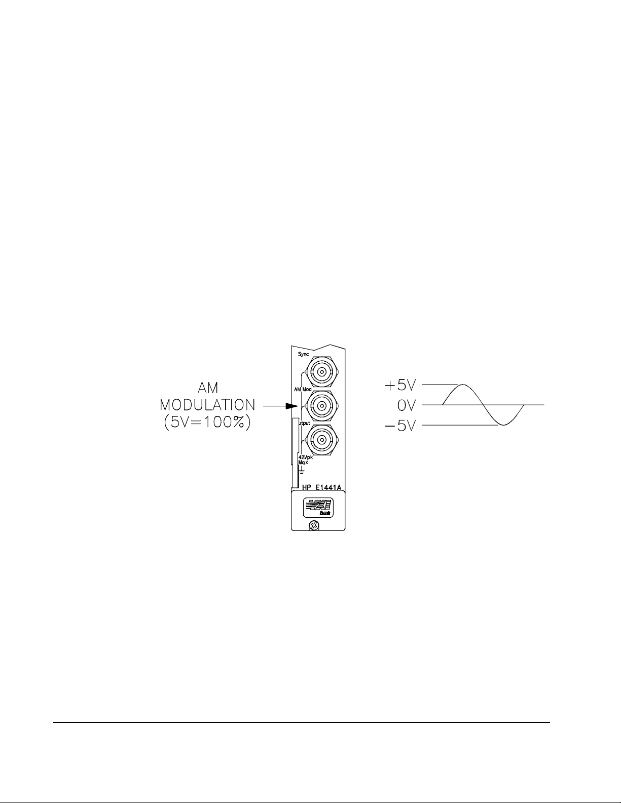
You apply the external modulating waveform to the AM Modulation
terminal. The modulation depth is controlled by the signal level present
(5 volts
peak corresponds to 100% modulation).
Figure 2-2 . AM M odulation In put Signal
Use the following command to set the modulat ing source:
AM:SOURce BOTH|EXTernal
Frequency
Modulation (FM)
A modulated waveform consists of a carrier waveform and a modulating
waveform. In
the modulating waveform. The function generator will accept only an
internal
covered on frequency modulation are:
FM modulating signal (no external source is available). Topics
• FM Carrier Waveform Shape
30 Agilent E1441A Application Information
FM, the frequency of the carrier is varied by the amplitude of
Chapter 2
Page 31

• FM Carrier Frequency
• Frequency Modulating Waveform Shape
• Frequency Modulating Waveform Frequency
• Peak Frequency Deviation
FM Carrier
Waveform Shape
Only one modulation mo de can be enabled at a time. When you enable
the previous modulation mode is tur ned off.
Use the following command to enable FM modulation: To ensure proper
operation, you should ena ble
parameters.
FM:STATe OFF|ON
FM carrier shape: Sine, Square, Triangle, Ramp, or Arbitrary waveform.
The default is Sine.
You cannot use the noise function or dc volts as the FM carrier waveform.
Use the following command to set the shape of the carrier waveform:
FUNCtion:SHAPe SINusoid|SQUare|TRIangle|RAMP|USER
You can also use the APPLy command to select the function, frequency,
amplitude, and offset with a single command. Because the APPLy command
also changes duty cycle, modulation type, trigger source, and trigger slope,
you must place the APPLy command fir st in any sequence of configur ation
commands.
FM after you have set up the other modulation
FM,
FM Carrier Frequency Carrier fre que n cy : 10 mHz to 15 MH z (1 00 kH z for trian gle and ramp).
The default is 1 kHz.
Chapter 2
For arbitrary waveforms, the maximum carrier frequency depends on the
number of points specified in the waveform. The five built-in arbitrary
waveforms can be output at a maximum of 5 MHz.
The carrier frequenc y must always be greater than or equal to the peak
frequency deviation. If you attempt to set the carrier frequ ency to a value less
than the deviation, the function generator will auto-matic ally adjust the
carrier freque ncy to equal th e present deviati on. A -221, “Set tings conflic t”
error is generated and the carrier frequency is adjusted.
The sum of the carrier frequency and peak frequency deviation must be le ss
than or equal to the maximum frequency for the selected function
100 kHz
and 5.1 MHz for arbitrary waveforms). If you attempt to set the carrier
frequency to a value that is not valid, the function generator will
automatically adj ust the carri er frequency to equa l the presen t deviation. A
-221, “Settings conflict” error is generated and the deviation is adjusted.
Use the following command to set the carrie r fre quency:
FREQuency <frequency>|MINimum|MAXimum
(15.1 MHz for sine and square, 200 kHz for triangle and ramp,
Agilent E1441A Application Information 31
plus
Page 32

FM Waveform Shape The function generator will accept only an internal modulating signal. You
cannot modulate with an externa l source.
Modulating waveform shape (internal source): Sine, Square, Triangle,
Ramp, Noise, or Arbitrary wavefor m. The defau lt is Sine.
You can use the noise function as the modulating wavefor m. However, you
cannot use the noise function or dc volts as the carrier waveform.
Use the following command to set the modulat ing waveform shape:
FM:INTernal:FUNCtion SIN|SQU|TRI|RAMP|NOIS|USER
FM Wav efo rm Freq uen cy The function generator will accept only an internal modulating signa l. You
cannot modulate with an externa l source.
Modulating frequency: 10 mHz to 10 kHz. The default is 10 Hz.
FM Peak Frequen cy
Deviation
The sync signal for
carrier). A momentary
FM is referenced to the modulating signa l (not the
TTL “high” pulse (> 200 ns) is output at each
zero-crossing point of the modulating signal. The signal is output from the
front-panel SYNC terminal.
Use the following command to set the modulat ing waveform frequency:
FM:INTernal:FREQuency <frequency>|MINimum|MAXimum
The peak frequency deviation represents the variation in frequency of the
modulating waveform from the carrier frequency.
Peak frequency deviati on: 10 mHz to 7.5 MHz. The default is 100 Hz.
The carrier frequency must always be greater than or equal to the peak
frequency deviation. If you attempt to set the deviation to a value greater
than the carrier frequency (with
FM enabled), the function gen erator will
automatically adjust the deviation to equal the present carrier frequency. A
-221, “Settings conflict” error is generate d and the deviation is adjusted.
The sum of the carrier f req u en cy and peak frequency deviation must be less
than or equal to the maximum frequency for the selected function
(15.1 MHz for sine and square, 200 kHz for triangle and ramp, and 5.1
kHz
plus 100
MHz for arbitrary wa veforms). I f you at tempt to se t the de viation t o a value
that is not valid, the function generator will automatically adjust the
deviation to the maximum value allowed wit h the present c arrier fr equency.
A -221, “Settings conflict” error is generated and the dev iation is adjusted.
Use the following command to set the peak frequency deviation:
FM:DEViation <peak deviation in Hz>|MINimum|MAXimum
32 Agilent E1441A Application Information
Chapter 2
Page 33

Burst Modulation You can configure the function genera tor to output a burst of waveform
cycles. The function generator can produce a burst using sine, square,
triangle, ramp, and arbit rary waveforms. Topics covered on burst
modulation are:
• “Burst Modes” on page 33
-- “ Counted Burst Mode” on page 33
-- “ Gated Burst Mode” on page 35
• “ B urst Trigger Source” on page 35
-- “For Counted Burst Mode” on page 35
-- “For Gated Burst Mode” on page 36
• “ B urst Carrier Frequency” on page 36
• “ B urst Count” on page 38
• “ B urst Rate” on page 39
• “ B urst Phase” on page 39
Only one modulation mode can be enabled at a time. When you enable the
burst mode, the previously enabled modulation mode is turned off.
Use the following command to enable burst modulation: To ensure proper
operation, you should enable the burst mode after you have set up the other
modulation parameters.
BM:STATe OFF|ON
Burst Modes There are two major modes of burst modul ation; the "counted" burst , and the
"gated" burst modes. In count ed mode, the length of the burst is controlled
by cycle count (BM:NCYCles). In gated mode, the duration of the burst is
controlled by an external "gate" signal. The BM:SOURce command selects
between the two modes:
BM:SOURce INTernal
BM:SOURce EXTernal
Counted Burst Mode
A counted burst is started by a trigger signal from either an internal trigger
timer (TRIG :SO U R IN Tern a l) , or an ext ern al sig nal
(TRIG:SOUR EXTernal|TTLTRG<n>|BUS). The duration of the burst is
set by specifying the number of wavefo rm cycle s (BM:NC YCles) .
Figure 2-3 shows the opera tion of the counted burst mode with internal
this select s the "counted" mode
this selects the "gated" mode
Chapter 2
Agilent E1441A Application Information 33
Page 34

trigger source.
CountedB urst Modu lation Output
Burst ModulationT rigger Signal
(INT ernaltimershown)
Figure 2-3. Counted Burst Mo de wi th INTernal Trigger
The command sequence to configure this mode is:
burststa rtson
rising edge
1/(Burst Rate)
burst ends when
count reached
APPLY:<shape> <freq>,<ampl>,<offset>
BM:STATE ON
BM:SOURce INTernal
TRIG:SOURce INTernal
BM:NCYCles <cycle_count>
BM:INTernal:RATE <frequency>
Figure 2-3 shows the opera tion of the counted burst mode with external
trigger source.
Counted Burst Modulation Output
Burst Modulation TriggerSignal
(TRIG:SOUR EXT,:SLOPE POS)
Figure 2-4. C ou nt ed Burst Mode wi th E XTernal Trigger
set up wave form
enable burst modul ation
this select s the "counted" mode
trigger from internal trigger
timer
set the bur st count
set the b urst re p rate
burst ends when
count reached
burst starts on edge
set by TRIG:SLOPE
The command sequence to configure this mode is:
APPLY:<shape> <freq>,<ampl>,<offset>
BM:STATE ON
BM:SOURce INTernal
TRIG:SOURce EXTernal|TTLTRG<0-7>|BUS
BM:NCYCles <cycle_count> set the bur st count
34 Agilent E1441A Application Information
set up wave form
enable burst modul ation
this select s the "counted" mode
use external trigger
Chapter 2
Page 35

Gated Burst Mode
There is only one form of the ga ted burst mode. The burst i s controlle d by a
gating signa l that i s supplied from an external tr igger so urce. The bur st starts
when the trigger signal is set to a TTL "high" level. The burst ends when the
gating signal returns to a TTL "low" level.
Gated Burst Modulation Output
Burst Modulation Gating Signal
(selected by TRIG:SOUR
either EXT or TTLTRG<0-7>)
NOTE: TTLTpolarity is always
the oppositeofthe of EXT TRIG
The command sequence to configure this mode is:
APPLy:<shape> <freq>,<ampl>,<offset>
BM:SOURce EXTernal
TRIG:SOURce EXTernal|TTLTRG<0-7>
BM:STATE ON
T able 2-5 shows an overview of the allowable burst mode configu rations
Table 2-5. Burst Mode Configurations
Burst Source
(BM:SOUR)
off period
(gate = 0)
on period
(gate = 1)
Figure 2-5. Gated Burst Mode
Trigger Source
TRIG:SOUR
Burst Count
(BM:NCYC)
set up wave form
this selects the "gated" mode
trigger from exter nal signal
AFTER all modulation AND
trigger selec tion, enable BMod
Burst Rate
(BM:INT:RATE)
Burst Phase
(BM:PHAS)
Counted Burst Modes INTernal INTernal Available Available Available
EXTernal, BUS,
or TTLTRG<n>
Gated Burst Mode External EXTernal or
TTLTRG<n.>
Burst Trigger Source For Counted Burst Mode
When the burst mode is set to "counted" (BM:SOUR INTernal), a trigger
Chapter 2
Available Not Used Available
Not Used Not Used Not Used
Agilent E1441A Application Information 35
Page 36

signal is required to start the waveform burst. The TRIGger:SOURce
choices are:
IMMediate Not available in Burst Modulation; specifying IMM
actually select s EXTernal
INTernal (the power-on/*RST default) This selects the internal
trigger timer. The timer’s repetition r ate is then set by
the BM:INTernal:RATE command.
BUS Burst can be triggered by a Group Execute Trigger
(GET) IEEE-488.1 command or the *TRG IEEE- 488.2
common command.
EXTernal This selects the "Ext Trig/FSK/Burst" connector as the
source of the trigger signal.
TTLTRG<n> Selects one of the 8 (TTLTRG0 through
TTLTRG7)VXIbus TTL trigger lines as the trigger
source.
For Gated Burst Mode
When the burs t mode is "g ated " (BM :SO U R EXTernal), the wa vefo rm
burst is controlled (gated) by an an ex te rnal trigg er. The ch oi ces for
TRIG:SOUR are:
EXTernal Selects the "EXT Trig/FSK/Burst" connector as the
source of the burst gating signal. Driven to a TTL
"high", the waveform is output. When at a TTL "low",
the output is at the DC offset voltage.
TTLTrg<n> Selects one of the 8 (TTLTRG0 through
TTLTRG7)VXIbus TTL trigger lines as the burst
gating signal. When the TTLTRG line is true, the
waveform is outpu t. When the line is false, t he output i s
at the DC offset volt ag e.
Bus, IMM,
and INT These are not valid choices for gated burst mode.
Specifying any of these selects EXTernal.
Use the following c ommand to select a trigger source for burst modulation:
TRIGger:SOURce EXTernal|BUS|TTLTrg<0 - 7>
See “Tri ggering th e Functi on Generator” on page 52. for more information
Burst Carrier Frequency The carrier frequency defines the repetition ra te of the burst waveform in the
triggered and external gated modes. In the triggered mode, the number of
cycles specified by the burst count are output at the frequency of th e carrier
signal. In the external gated mode, the carrier frequency is output when the
external gate signal is tr ue (
TTL high).
36 Agilent E1441A Application Information
Chapter 2
Page 37

Keep in mind that the carrier frequen cy is diffe rent than the “burst rate”
which specifies the interval between bursts (triggered mode only).
Burst Carrier freque ncy: 10 mHz to 5 MHz (100 kHz for triangle and
ramp). The default is 1 kHz. You can use sine, square, ramp, triangle, or
arbitrary wav ef o rms fo r the ca rri er w aves hap e .
Be sure to note the re strictions for carrier frequency and bur st count shown
on the following pages.
For arbitrary waveforms used as the carrier wavef orm, the maximum
frequency depends on the number of points specified in the waveform. The
five built-in arbi trary wavefor ms can b e output at a max imum of 5 MHz (be
sure to note the restrictions below).
Table 2-6.
Number of Arb Poi nts Minimum Frequency Maximum Frequency
8 to 8,192 (8k) 100 mHz 5 MHz
8,193 to 12, 287 (12k) 100 mHz 2.5 MHz
12,288 to 16,000 100 mHz 200 kHz
For sine, square, and arbitrary waveforms (does not apply to ramp and
triangle waveforms), the relati onship betwee n the carrier freque ncy and the
minimum burst count is shown below.
Table 2-7.
Carrier Frequency Minimum
Burst Count
10 mHz to 1 MHz 1
>1 MHz to 2 MHz 2
>2 MHz to 3 MHz 3
>3 MHz to 4 MHz 4
>4 MHz to 5 MHz 5
If you attempt to set the carrier fr equency to a value that is not valid,
the function generator will automatically adjus t the freque ncy to the
maximum value allowe d with the present burst count. A -221, “Settings
conflict” error is gen erated and the carrier frequency is adjusted.
Chapter 2
Agilent E1441A Application Information 37
Page 38

For all waveforms used with burst, if t he carrier f reque ncy is s et le ss than or
Burst Count
s
equal to 100 Hz, the following relationship applies.
-------------------------------------------------- -
Carrier Frequency
500 ond
sec≤
for Carrier ≤ 100 Ηz
If you attempt to set the carrier fr equency to a value that is not valid, the
function generato r will automatically adjust the fre quency to the minimum
value allowed with the present burst co unt. A -221, “Settings conflict ” error
is generated and the frequency is adjusted.
For the counted burst mode, the sync signal is a
TTL “low” while the
specified number of cycl es is output (for the durat ion of the burst). After the
specified number of cyc les has been output, the sync signal goe s “high” until
the next burst. The sync signal is out put from the front-panel SYNC terminal.
For the external gated burst mode, the sync signal is a
TTL “high” when the
output is positi ve, relative to zero volts (or the dc offset value). The signal is
a
TTL “low” when the output is negative, relative to zero volts (or the dc
offset value) . The sync si gnal i s out put fr om the f ront-pa nel SYNC terminal.
Use the following command to set the freque ncy:
FREQuency <frequency>|MINimum|MAXimum
You can also use the APPLy command to select the function, frequency,
amplitude, and offset of the carrier with a single command. Because the
APPLy command also changes duty cyc le, modula tion type, trigger source,
and trigger s lope, you must pla ce the APPLy comman d first in any sequence
of configuration commands.
Burst Count The burst count defines the number of cycl es to be output per burst. Used
only in the "counted" burst mode (internal or external trigger).
Certain combinations of burst co unt and carrier freque ncy are not allowed.
If you attempt to specify a burst count that is not valid, the function
generator will automat ically adjust the count to the maximum value
allowed with the present carrier frequency.
Make sure you note the restrictions in “Burst Carrier Frequency” before
setting the burst count.
Burst count:
an infinite burst count. The default is 1 cycle.
When the internal trigger timer is selected (TRIG:SOUR INT), the specified
number of cycles is out put ea ch time the tim ed tr igger occur s. the repetit ion
rate of the trigger timer is set by BM:INTernal:RATE <freq>.
When an external trigger source is selected
(TRIG:SOUR EXT|TTLTRG<n>), the burst count and burst phase remain
in effect but the burst rate is ignored. The specified number of cycles is
output each time a trigger signa l is applied to the selected trigge r source. The
1 to 50,000 cycl es, i n 1 cycle in crements. You can a ls o selec t
38 Agilent E1441A Application Information
Chapter 2
Page 39

function generato r is triggered on the rising edge of the trigger source.
When the "gated" burst mode is selected, the burst count, burst rate, and
burst phase are ignored (the se parameters are used for the counted burst
mode only).
Use the following command to set the burst count:
BM:NCYCles <# cycles>|INFinity|MINimum|MAXimum
Burst Rate The bu rst rate defines the freque ncy at whic h internally triggered bursts are
generated. The burst rate fre quency defines the interval betwe en bursts.
Used only in the counted burst mode (with TRIG:SOUR INTernal).
Keep in mind that the burst rate is different than the “carrier frequency”
which specifies the frequency of the bur st signal.
Burst rate: 10 mHz to 50 kHz. The default is 100 Hz.
When in "coun ted" burst mode, but with an external trigger source selected
(TRIG:SOUR EXT|TTLTRG<n>), the burst count and burst phase remain
in effect but the burst rate is ignored.
When the "gated" burst mode is selected, the burst count, burst rate, and
burst phase are ignored (the se parameters are used for the counted burst
mode only).
It is possible to specify a burst r ate which is too fast for the function
generator to output with the specified carrier frequency and burst count. If
the burst rate is too high, the function generator will internally adjust it as
needed to allow repeated triggering the burst. The adjustment is han dled
internally by the funct ion generator (the burst queried will be the same as
specified).
Use the following command to set the burst rat e:
BM:INTernal:RATE <frequency>|MINimum|MAXimum
Burst Phase The burst phase defi nes the starting phase of the burst.
Burst phase: -360 degrees to +360 degrees, in 0.001 degr ee inc rements.
The default is 0 degrees.
For sine, square, triangle, and ramp waveforms, 0 degrees is the point at
which the waveform crosses zero volts (or the dc offset value), in a
positive-going direction.
For arbitrary waveforms, 0 degrees is the first data point downloaded to
memory.
When the "gated" burst mode is selected, the burst count, burst rate, and
burst phase a re ignored (these parameters are used for the "counted" burst
mode only).
Chapter 2
Agilent E1441A Application Information 39
Page 40

Use the following command to set the burst phas e:
BM:PHASe <degrees>|MINimum|MAXimum
Frequency-Shift
Keying (FSK)
Modulation
You can configure the function gen era tor to “shift” its output frequency
between two preset values using
output shifts be tween the two freque ncies (called the “carrier frequency” and
the “hop frequency”) is determined by the internal rate generator or the
signal level on the"Ext Trig/FSK/Burst terminal". The function generator
can produce an FSK waveform using sine, square , triangle, ramp, and
arbitrary wavefor ms. Topics covered on frequency-shif t keying modulation
are:
FSK modulation. The rate at which the
• “ F SK Carrier Frequency” on page 40
• “FSK “Hop” Frequency” on page 41
• “FSK Rate” on page 41
• “FSK "Hop" Source” on page 42
-- “Internal Hop Source” on page 42
-- “ External Hop Source” on page 42
Only one modulation m ode can be e nabled at a time. When you enable
the previous modulation mode is tur ned off.
Use the following command to enable freque nc y-shift keying:To ensure
proper operation, you should enable
modulation parameters.
FSKey:STATe OFF|ON
FSK after you have set up the other
FSK,
FSK Carrier Frequency FSK Carrier frequency: 10 mHz to 15 MHz (100 kHz for triangle
and ramp). The de fault is 1 k Hz. You can us e sine , squa re, r amp, tr iangle, or
arbitrary wav ef o rms fo r the ca rri er w aveform.
For arbitrary waveforms, the maximum carrier frequency depends on the
number of points specified in the waveform. The five built-in arbitrary
waveforms can be output at a maximum of 5 MHz.
Table 2-8.
Number of Arb Poi nts Minimum Frequency Maximum Frequency
8 to 8,192 (8k) 100 mHz 5 MHz
8,193 to 12, 287 (12k) 100 mHz 2.5 MHz
12,288 to 16,000 100 mHz 200 kHz
For an external ly -co nt ro lle d
when a "low"
command. The hop frequency is output when a “high”
For
FSK, the sync signal is referenced to the FSK “hop” signal (not the
carrier). A momentary
to the “hop” frequency. The signal is output from the front- panel Sync
terminal.
TTL level is applie d to the source selec ted by the TRIG:SOUR
FSK waveform, the carrier frequency is output
TTL level is applied.
TTL “high” pulse (> 200 ns) is output on the transition
40 Agilent E1441A Application Information
Chapter 2
Page 41

Use the following command to set the freque ncy:
FREQuency <frequency>|MINimum|MAXimum
You can also use the APPLy command to select the function, frequency,
amplitude, and offset of the carrier with a single command. Because the
APPLy command also changes duty cyc le, modula tion type, trigger source,
and trigger s lope, you must pla ce the APPLy comman d first in any sequence
of configuration commands.
FSK “Hop” Frequency Hop frequency: 10 mHz to 15 MHz (100 kHz for triangle and r amp). The
default is 100 Hz. You can use sine , square, ramp, triangle, or arbitrary
waveforms for the hop frequency waveshape.
For arbitrary waveforms, the maximum hop frequency depends on the
number of points specified in the waveform. The five built-in arbitrary
waveforms can be output at a maximum of 5 MHz.
Table 2-9.
Number of Arb Poi nts Minimum Frequency Maximum Frequency
8 to 8,192 (8k) 100 mHz 5 MHz
8,193 to 12, 287 (12k) 100 mHz 2.5 MHz
12,288 to 16,000 100 mHz 200 kHz
For an external ly -co nt ro lle d
when a “low”
TTL level is applie d to the FSK terminal. The hop frequency
is output when a “high”
For
FSK, the sync signal is referenced to the FSK “hop” signal (not the
carrier). A momentary
FSK waveform, the carrier frequency is output
TTL level is applied.
TTL “high” pulse (> 200 ns) is output on the transition
to the “hop” frequency. The signal is output from the front- panel SYNC
terminal.
Use the following command to set the FSK frequency:
FSKey:FREQuency <frequency>|MINimum|MAXimum
FSK Rate The FSK rate is the r ate at which the output frequency “ shifts” between the
carrier frequen cy and the hop freque ncy when you select the internal
source (FSK :SO U R INTe rn al).
FSK rate (internal source ): 10 mHz to 50 kHz. The default is 10 Hz.
FSK
Chapter 2
The
FSK rate is ignored when the external source is selected.
Use the following command to set the FSK rate:
FSKey:INTernal:RATE <rate in Hz>|MINimum|MAXimum
Agilent E1441A Application Information 41
Page 42

FSK "Hop" Source FSK source: Internal or External. The default is Internal.
Internal Hop Source
When FSK:SOUR is INTernal, the rate at which the output frequency
“shifts” between the car rier frequency and hop frequency is deter mined by
the FSK rate specified. Figure 2-6 shows FSK operati on with INTernal hop
control
FSK Output (sine)
Carrier period
INTernal Hop Signal
1/(FSK Rate)
Hop period
Figure 2-6. Frequency Shift Keying with INTernal Hop Signal
External Hop Source
When FSK:SOUR is EXTernal, the output frequency is determined by the
signal level of the source selected by the TRIG:SOUR command. When a
“low”
TTL level is present on the Ext Trig BNC, the carrier frequency is
output. When a “high”
TTL level is present on the Ext Trig BNC, the hop
frequency is output. This logic sense is inverted for the TTLTRG lines.
Figure 2-7 shows FSK operation with external hop control
FSK Output (sine)
External Hop Signal
(selected by TRIG:SOUR
either EXT or TTLTRG<0-7>)
NOTE: TTLT polarity is alway s
the opposite of the of EXT TRIG
Figure 2-7. Frequency Shift Keying with EXTernal Hop Signal
Use the following command to select the external FSK source:
42 Agilent E1441A Application Information
Carrier period
Hop period
Chapter 2
Page 43

FSKey:SOURce EXTernal
TRIGger:SOURce EXT | TTLT<0-7>
select ext FSK source
now select which ext source
Frequency Sweep In the frequency sweep mode, th e function generator “steps” from the start
frequency to the stop frequency at a sweep rate whic h you specify. You can
sweep up or down in frequency, and with either linear or logarithm ic
spacing. You can also configure the function generator to output a single
sweep (one pass from start frequency to stop frequency) by applying a n
external trigger. The function generator can produce a freq uency sweep for
sine, square, triangle , ramp, or arbitrary waveforms. Topi cs covere d on
frequency sweep are:
• “ S weep Start and Stop Frequencies” on page 43
• “ S weep Time” on page 43
• “Sweep Mode” on page 44
• “ S weep Trigger Source” on page 44
Only one modulation mode can be enabled at a time. When you enable the
sweep mode, the previous modulation mode is turned off.
Use the following command to enable the frequency sweep:To ensure
proper operation, you should enable the sweep mode after you have set up
the other modulation parameters.
Sweep Start and Stop
Frequencies
SWEep:STATe OFF|ON
The start frequency and stop frequency set the upper and lower frequen cy
bounds for the sweep. The function generator begins at the start frequenc y,
sweeps to the stop frequency, and then rese ts back to the start frequency.
Start and Stop fre quencies: 10 mHz to 15 MHz (100 kHz for triangle and
ramp). The sweep is phase continuous over the full frequency range. The
default start frequency is 100 Hz. The default stop frequency is 1 kHz. The
*RST command sets the start frequency to 10 mHz (minimum) an d t he s top
frequency to 15 MHz (maximum).
For arbitrary waveforms, the maximum start or stop frequency depends on
the number of points specifi ed in the waveform. The five built-in arbitrary
waveforms can be output at a maximum of 5 MHz.
To sweep
To sweep
The sync signal is a
frequency is output) and is a
stop frequency is output) . The signal is output from the front-panel SYNC
terminal.
Use the following command set the start and stop frequencies:
up in frequency, set the start frequency < stop f r eque n c y .
down in frequency, set the start frequency > stop frequency.
TTL “low” at the start of the sweep (when the start
TTL “high” at the end of the sweep (when the
Chapter 2
FREQuency:STARt <frequency>|MINimum|MAXimum
FREQuency:STOP <frequency>|MINimum|MAXimum
Sweep Time The sweep time spe cif ies the number of seconds re quire d to sweep from th e
Agilent E1441A Application Information 43
Page 44
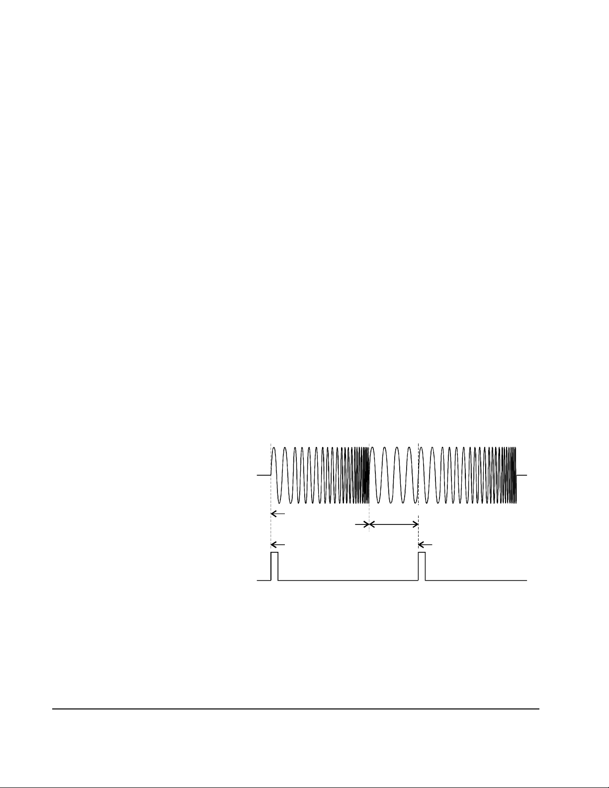
start frequency to the stop frequency. The numbe r of frequency points in the
sweep depends on the swee p time y ou se lect and is a utomaticall y c alcula ted
by the function generator .
Sweep time: 1 ms to 500 seconds. The default is 1 second.
The function ge nerator computes between 2,048 and 4,096 freque ncy points
from the start frequency to the stop frequency.
Use the following command to set the sweep time:
SWEep:TIME <seconds>|MINimum|MAXimum
Sweep Mode You can sweep with either linear or logarithmic spacing. The output
frequency of a linear sweep changes linearly during the duration of the
sweep. For logarithmic spacing, the ou tput frequency changes expon entially
during the duration of the sweep.
Sweep mode:
Linear or Logarithmic. The default is Linear.
Use the following command to set the sweep mode:
SWEep:SPACing LINear|LOGarithmic
Sweep Trigger Source External Sources
In the triggered sweep mode (TRIG:SOUR other than IMMediate), the
function generato r outputs a single sweep each time a trigger is received.
After one swee p from the sta rt frequency to the sto p fr equency, the func ti on
generator waits for the next trigger while outputting the start
frequency.Figure 2-8 shows the frequency sweep operation with "external"
trigger (IMMediate , EXTernal, TTLTRG<n> , or BUS). The defaul t is IMM.
Frequency Sweep Output
sweep start
frequency
begin sweep begin sweep
sweep stop
frequency
idle at start
frequency
Sweep Trigger Signal
(TRIG:SOUR is EXT|
BUS|TTLTRG<N>)
Figure 2-8. Frequency Sweep with "EXT ernal" Trigger
Internal Source
When the internal trigger source is selected (TRIG:SOUR IMMediate), the
function generato r repea tedly outputs a frequency sweep at a rate
44 Agilent E1441A Application Information
Chapter 2
Page 45

determined by the sweep rate specified. Figure 2-9 shows the frequency
sweep operation with internal trigger source.
Frequency Sweep Output
Sweep Trigger Signal
(TRIG:SOUR INT shown)
Figure 2-9. Fr e qu e ncy Sweep wit h In te rnal Trigger
Use the following command to set the sweep trigger source:
TRIGger:SOURce IMMediate|EXTernal|TTLTRG<0-7>|BUS
See “Tri ggering the Function Generator” on page 52. for more information.
sweep start
frequency
sweep time
sweep stop
frequency
Chapter 2
Agilent E1441A Application Information 45
Page 46

Arbitrary
Waveforms
There are five built-in arbitrary waveforms stored in non-volatile memory.
You can also download up to four user-def ined arbitrary waveforms into
non-volatile memory. Each waveform can contain between 8 and 16,000
data points. Topics covered on arbitrary waveforms are:
• Creating Arbitrary Waveforms
• Creating and Storing an Arbitrary Waveform
• Built-In Arbitrary Waveforms
Creating Arbitrary
Waveforms
For most applications, it is not necessary to create a waveform of any
specific length sinc e the fun ction generator will automatically sample the
available data to produc e an output signa l. In fact, it is generally best to
create arbitrar y waveforms which use all available data (16,00 0 points long
and the full range from 0 to 4,095
do not have to change the length of the waveform to change its output
frequency. All you have to do is create a waveform of any length and then
adjust the functi on generator's output fre quency. Remember, if you create an
arbitrary waveform that includes three cycles of the same waveshape , the
output frequency will actua lly be three times the value you set with the
frequency comman d.
When creating arbitrary waveforms, you have control of both th e amplitude
quantization and phase truncation errors. For example, pha se truncation
harmonics will be generate d when a waveform is crea ted using the full
amplitude range of the
waveform data points. In this case , the amplitude quantiza tion errors will be
near the noise f loor while the time quantiz ation error will produ ce harmonics
near the -60 dBc level. Similarly, amplitude quantization harmonics will be
generated when you create a waveform using less than the full amplitude
resolution of the func tion generator. For example, if you use only one-fifth
of the available amplit ude res olution, amplitude quantization will produce
harmonics below the -60 dBc level.
When importing da ta from instruments such a s oscilloscopes, the data will
generally range between 1,024 and 4,096 time points and between 64 and
256 amplitude points.
DAC (12 bits) but is created using only 1,000
DAC codes). For the Agilent E1441A, you
When creating arbitrar y waveforms, the function generator will always
attempt to replicate the finite-length time record to produce a periodic
version of the data in waveform memory. As shown on the next page, it is
possible that the sha pe and phase of a signal may be such that a tra nsient is
introduced at the e nd point. When the waveshape is rep eated for all time, this
end-point transient will introduce leakage error in the frequency domain
because many spectral ter ms are requir ed to describe the discontinuity.
Leakage erro r is caus ed wh en the w av eform record does not inclu de an
integer number of cycles of the funda menta l frequency. Power from the
fundamental frequency, and its harmonics, is transferred to spectral
components of the rectangular sampling function. Instead of the expecte d
narrow spectral line s, le akage can cause significant spre ading around the
desired spectral pe aks. You can reduce leakage errors by adjusting the
window length to include an int eger number of cyc les or by includi ng more
cycles within the window to reduce the residual end-point transient size.
Some signals are composed of discrete, non-harmonically relate d
46 Agilent E1441A Application Information
Chapter 2
Page 47

frequencies. Since these signals are non-repetitive, all frequency
components cannot be harmonically related to the window length. You
should be careful in these sit uat ions to minimize end-point discontinuities
and spectral leakage.
Creating and Storing an
Arbitrary Waveform
The following is an overview of the steps required to download and output
an arbitrary waveform. The commands used for arbitrary waveforms are
listed on page
Chapter 2, “Application Programs”, contains an example program which
shows the use of arbitrary waveforms. You may find i t useful to refer to the
program after reading the following section in this chapter.
1. Select the waveform frequency, amplitude, and offset.
Use the
APPLy command or the equivalent FREQ, VOLT, and VOLT:OFFS
commands to select the frequency, amplitude, and offset of the arbitrary
waveform. Because the APPLy command also changes duty cycle,
modulation type, trigger source, and trigger slope, you must place the
APPLy command first in any sequence of configu ration commands.
2. Download the data points into volatile memory.
You can download between 8 and 16,000 points per wavefor m.
The waveform can be downloa ded as floating-point values or binary i nteger
values. Use the
values between -1 and +1. Use the
DATA VOLATILE command to download floating-point
DATA:DAC VOLATILE command to
download binary integer values between -2047 and +2047.
To ensure that binary data is downloaded properly, you must select the order
in which the bytes are downloaded using the
FORM:BORD command.
3. Copy the arbitrary waveform to non-volatile memory.
You can output the arbitrary waveform directly from volatile memory (as
described i n step 2) or you can copy the waveform t o non-volatile memory.
Use the
DATA:COPY command to copy the waveform to non-volatile
memory.
4. Select the arbitrary waveform to output.
You can select one of the five built-in a rbitrary waveforms, one of four
user-defined waveforms, or the waveform current ly downloaded to volatile
memory. Use the
FUNC:USER command to se lect the w avef or m.
5. Output the currently selected arbitrary waveform.
Use the
selected with the
FUNC:SHAP USER command to output the waveform previousl y
FUNC:USER command.
Chapter 2
Agilent E1441A Application Information 47
Page 48

Built-In Arbitrary
Waveforms
The five built-in arbi trary waveforms are shown below.
48 Agilent E1441A Application Information
Figure 2-10.
Chapter 2
Page 49

Phase-Lock
Capabilities
(Opt 001)
This section gives a n overview of the basic tec hniques used to program the
Phase-Lock option ( option 001). This section is only an overview and does
not give all of the details you will nee d to write your own application
programs. Refer to “Application Program Examples,” later in this chapter
for more details and examples. Also refer to the programming reference
manual that came with your computer for details on outputting command
strings and entering dat a.
To Phase Lock to an
External Clock Signal
(requires Option 001)
The front-panel 10 MHz Ref In terminal allows you to synchronize one or
more function generator s with an external 10 MHz signal. The following
statements show how to configure a single instrument for synchronization
with an external signal:
APPL:SIN 10E+6, 5.0 Select sine function at 10 MHz
PHAS:ADJ -90 DEG Set phase offse t to -90 degrees
PHAS:REF
Set phase refe re nce to zero
Chapter 2
Figure 2-11.
Agilent E1441A Application Information 49
Page 50

To Phase Lock Multiple
Function Generators
(requires Option 001)
The front-panel 10 MHz Ref Out and 10 MHz Ref In termina ls allow you to
synchronize multiple function generators. The following statements show
you how to synchronize two function gene rators at 10 kHz (send the
commands to both function generators):
APPL:SIN 10E+3, 5.0
PHAS:ADJ -90 DEG
PHAS:REF
Select sine function at 10 kHz
Set phase offse t to -90 degrees
Set phase refe re nce to zero
50 Agilent E1441A Application Information
Figure 2-12.
Chapter 2
Page 51

To Phase Lock Using the
Counted Burst Mode
(requires Option 001)
In the counte d burs t mode , you c an syn chronize p hase- lock signals using an
external trigg er fro m the facep lat e Ext Trig terminal or VXIbus TTLTRG
lines. The following statements show you how to synchronize two function
generators in the counted burst mode using the Ext Trig termin al (se n d the
commands to both function generators):
Send these co mm a nd s to both func ti on generators:
APPL:SIN 10E+3, 5.0
BM:NCYC INF
TRIG:SOUR EXT
BM:STAT ON Enable the BMod LAST
Set both to the same frequency
Set burst count to “
Set trigger s ource to external
INFINITY"
Send this com ma nd on ly to the "left" function g ene ra to r:
OUTP:TRIG:IMM source trig ger signal from "left"
instrument to rught instrument
Chapter 2
Figure 2-13.
To use TTLTRG lines send these commands to both generators:
APPL:SIN 10E+3, 5.0
BM:NCYC INF
OUTP:TTLT4 ON
TRIG:SOUR TTLT4
BM:STAT ON
Set both to the same frequency
Set burst count to “
Enable TTLT4 line to source
Set trigger s ource toTTLT4 line
Enable the burst mode LAST
INFINITY"
Send this com ma nd on ly to the "left" function g ene ra to r:
OUTP:TRIG:IMM
source trig ger si gnal from "left"
You don’t have to connect between the Ext Trig terminals when using the
TTLTRG lines.
Agilent E1441A Application Information 51
Page 52

T r iggering the
Function Generator
Note TRIG:SL OPE se lect s the slop e o f the trigger source only. Where the
Applies only to counted bursts and frequency sweep, not gated modes such
as Gated Bursts, or FSK modulation. You can issue triggers for bursts and
sweeps using internal triggering or external triggering. Topics covered on
triggering are:
• “Trigger Source Choices” on page 52
• “Ext Trig / FSK / Burst Input Terminal” on page 54
Trigger Slope
The Agilent E1441A includes a choice of trigger polarity when the source
in an external or one of the 8 VXIbus TTLTRG lines. The command to select
the trigger polarity is:
TRIGger:SLOPe POSitive | NEGative
external trigge r sources ("Ext Trig" and TTLTRG lines) are being used as a
gating signal for Burst and FSK, the setting of TRIG:SLOPE is ignored
POS: (*RST state) For TRIG:SOUR EXT (Ext Trig/FSK/Burst terminal);
triggers on positive going TTL signal.
For TRIG:SOUR TTLT<0-7>; triggers on negative
going signal on VXIbus TTLTRG line (ground true
logic)
NEG: For TRIG:SOUR EXT (Ext Trig/FSK/Burst terminal);
triggers on negative going TTL signal.
For TRIG:SOUR TTLT<0-7>; triggers on positive
going signal on VXIbus TTLTRG line (+ true logic)
Trigger Source Choices
Again, the applies only to counted burst and sweep. You must specify the
source from which the function generator will accept a trigger.
The function generator will accept a software (bus) trigger, a hardware
trigger from the Ext Trig terminal or VXIbus TTLTRG lines, or an
immediate internal trigger.
The trigger source sett ing is stored in volatile memory; the source is se t to
immediate when power has been off or after resetting the module.
To select the trigger sour ce, use the following command.
TRIGger:SOURce BUS|EXTernal|IMMediate|TTLTrg<0-7>
The APPLy command automatically sets the trigger source to IMMediate
52 Agilent E1441A Application Information
Chapter 2
Page 53

Internal Triggering
Internal triggering is enabled when you turn on the function generator. In
this mode, the function generator uses a repetitive trigger signal that
internally tr iggers waveform bursts or frequency sweeps. The rate at which
the internal t imer genera tes trigge rs is de pendant on t he b urst rat e, or sweep
time set (See “ Burst Rate” on page 39. and See “Sweep T i me” on page 43.).
To select the internal tr igger source for counted bursts, use the following
commands:
SOUR:BM:STATe ON
SOUR:BM:SOURCE INTernal
TRIGGER:SOURCE INTernal
To select the internal tr igger source for freque ncy sweeps, use the following
commands:
SOUR:SWEEP:STATE ON
TRIGGER:SOURCE IMMediate
The *RST and APPLy commands automatically sets the tr igger source to
IMMediate.
External Triggering (Including TTLTRG lines)
In this trigger mode, the function generator will accept a hardware trigger
applied to the Ext Trig termina l, or one of the VXIbus TTLTRG lines. The
function genera tor outp uts one bur st or init iates one sweep each time one of
these trigger inputs r eceives the proper polarity of signal e dge (set by
TRIG:SLOPE). NOTE that the default logical sense of the TTLTRG lines,
as defined by the VXIbus standard, is negative true. See also“Ext
Trig / FSK / Burst Input Terminal” on page 54.
Use the following command to set the trigg er source to external:
TRIGger:SOURce EXTernal
Use the following command to set the trigg er source to one of the VXIbus
TTLTRG lines:
TRIGger:SOURce TTLTrg<
0-7
>
Software (BUS) Trigge ring
When TRIG:SOUR is BUS, the function generator can be triggered by
sending an GPIB bus trigger command. The function generator outputs
one burst or initiates one sweep each tim e the trigger command is received.
To select the bus trigger source, se nd the following command.
TRIGGER:SOURCE BUS
Chapter 2
To trigger the function gene rator send the *TRG (trigger) command.
You can also trigger the function ge nera tor from the
Agilent E1441A Application Information 53
GPIB interface via the
Page 54

command module by sending the IEEE-488 Group Execute Trigger (GET)
message.
Ext Trig / FSK / Burst
Input Terminal
The input requirement f or an external trigger, FSK input or Burst input is a
TTL positive-going (when TRIG:SLOPE is POS) or negative-going (when
TRIG:SLOPE is NEG) pulse that must be >2 microsecond in duration.
The Ext/FSK/Burst Input ter minal is used in the following modes:
Figure 2-14.
Triggered Sweep Mode:Execute
TRIG:SOUR EXT or TTLT<0-7> to
enable the triggered sweep mode (sweeps must be enabled). When the edge
(polarity set by TRIG:SLOPE) of a TTL pulse is received on the Ext Trig
terminal or VXI bus TTLTRG line, the function generator outputs a single
sweep.
Externally-Modulated FSK Mode: To enable the externally-modulated
mode, execute
is present, the
present, the
Counted Burst Mode: Execute
FSK:SOUR EXT when FSK is enabl ed. W hen a low TTL level
FSK carrier frequency is output. When a high TTL level is
FSK “hop” frequency is output.
TRIG:SOUR EXT to enable the counted
burst mode (burst must be enabled). When t he rising edge o f a TTL pul se is
received, the f unction genera tor outputs a burst wavefor m with the sp ecified
number of cycles.
External Gated Burst Mode: To enable the external gated mode, execute
BM:SOUR EXT when bu r st i s en ab l ed. W hen a high TTL level is present, the
function generator outputs the carrier waveform. When a low
TTL level is
present, the output is disabled.
54 Agilent E1441A Application Information
Chapter 2
Page 55

System-Related Operations
This section gives information on topics such as error conditions and
self-test. Thi s inf ormation is not directly rela ted to waveform generation but
is an importa nt part of oper ating the function generator. Topics covered on
system-related ope rations are:
• Error Conditions
• Self-Test
• Memory State
• Firmware Revision Query
• SCPI Language Version Query
Error Conditions When the fa cep lat e Errors LED turns on, one or more command syntax or
hardware errors ha ve been detected. A record of up to 20 errors can be stored
in the function ge nerator's error queue. See Appendix B, “Error Messages,”
for a complete listing of the errors.
Errors are retrieved in first-in-first-out (
is the first error that was stored. When you have read all errors from the
queue, the
If more than 20 err ors hav e o ccurred, the last erro r store d in the que ue (the
most recent error) is replaced with -350, “Too many errors”. No additional
errors are stored until you r emove errors from the queue. If no errors have
occurred when you read the error queue, the function generator responds
with +0, “No error”.
The error queue is cleared when power ha s been off or after a *CLS (clear
status) command has been executed. The *RST (reset) command does not
clear the error queue.
Use the following command to check for system errors:
SYSTem:ERRor?
Errors have the following format (the error string may contain up to 80
characters):
Errors LED turns off.
-113,"Undefined header"
FIFO) order. The first error returned
Reads one error from the error
queue
Self-Test A pow er-on self-test occurs automatically when you turn on the function
generator. This limited test assures you that the function generator is
operational.
Chapter 2
A complete self-te st ru ns a series of tests and takes approximately
10 seconds to exec ute. If all test s pass, you can have a high confidence that
the function generator is fully operational.
If the self-tes t fails, the
be returned to Agilent Technol ogie s for service.
Errors LED turns on the function generator should
Agilent E1441A Application Information 55
Page 56

Use the following command to perform a self-test:
*TST?
Returns “0” if the self-test passes or “1” if it fails. If the self-test fails, an
error message is also generated with additional information on why the test
failed. Use the SYSTem:ERRor? command to read the error queue.
Memory Locations Four memory locations (numbered 0, 1, 2 and 3) are available to store
instrument configur ation states. See the *SAV, *RCL and MEMory
commands for mo re i nfo rm at ion.
Firmware Revision
Query
SCPI Language
Version Query
The function generator has two microprocessors for control of vario us
internal systems. You can query the function generator to dete rmine which
revision of f irmware is installed for each microprocessor.
The function generator returns two numbers. The first number is the
firmware revision number for the main generator processor and the second
is for the input/output processor.
Use the following command to query the firmw are version:
*IDN?
Returns “GPIB,E1441A,0,A.01.00-A.01.09”
Be sure to dimension a string variable with at least 41 characters.
You can determine the SCPI version with which the function generator is in
compliance by sending a query from the remote interface.
Use the following command to query the SCPI version:
SYSTem:VERSion?
Returns a string in the form “YYYY.V” where the “Y's” represe nt the year
of the version, and the “V” represent s a version number for that year
(for example, 1993.0).
56 Agilent E1441A Application Information
Chapter 2
Page 57

Power-On and
Reset State
Feature Power-On and Reset State
Output Configuration
Function Sine wave
Frequency 1 kHz
Amplitude (into 50 ohms) 100 mV peak-to-peak
Offset 0.00 Vdc
Output Units Volts peak-to-peak
Output Termination 50 ohms
Modulation
AM Carrier Waveform 1 kHz Sine wave
AM Modu lating Waveform 100 Hz Sine wave
AM Depth 100%
FM Carrier Waveform 1 kHz Sine wave
FM Modulating Waveform 10 Hz Sine wave
FM Peak Frequency Deviation 100 Hz
Burst Carrier Frequency 1 kHz Sine wave
Burst Count 1 cycle
Burst Rate 100 Hz
Burst Starting Phase 0 degrees
FSK Carrier Frequency 1 kHz Sine wave
FSK"Hop" Frequency 100 Hz Sine wave
FSK Rate 1 0 Hz
Modulation State Off
Sweep Start / Stop Frequency 100 Hz / 1 kHz
Sweep Time 1 second
Sweep Mo de Linea r
Triggering Operations
Trigger Source Internal
Calibration
Calibration State Doesn’t cha nge with *RST or
power-down. See page 74
Chapter 2
Note The power-on state will state will be different if you have enabled the
auto-recall mode. See “MEMory:STATe:RECall:AUTO OFF | ON | 0 | 1”
on page 85.
Agilent E1441A Application Information 57
Page 58

Application Program Examples
This section provide s progra ms that d emonstrate several ap plica tions of th e
Agilent E1441A. You can use these examples to help you learn the
capabilitie s of the Agilent E1441A and then to help you develop programs
for your specific application.
C Language
Programs
Compiling an d
Linking a C
Program
Example Pro grams
/* 1441brst.C - This program sets up a 10,000 cycle sine wave burst with */
/* a 270 degree starting phase. An offset voltage is added to the burst */
/* to cr e at e a h av e rs in e . * /
#include <stdio.h>
#include <visa.h>
/*** FUNCTION PROTOTYPE ***/
void err_handler (ViSession vi, ViStatus x);
#define DEVICE_ADDRESS "GPIB-VXI0::80::INSTR"
All of the C Language example programs in this section are written for the
Agilent 82341A GPIB Interface Card using the Agilent VISA I/ O Library.
You can find S pecific instructions for compiling C language programs for
the PC in the Agilent VISA User’s Guide. See the section "Compiling and
Linking an Agile nt VISA Program.
Burst Modulation Program
void main(void)
{
char buf[512] = {0};
ViStatus err;
ViSession defaultRM, funcgen;
/* Open resource manager and Function Generator sessions*/
err=viOpenDefaultRM(&defaultRM);
if(err != VI_SUCCESS) err_handler(funcgen, err);
else printf("default RM opened OK\n");
err=viOpen(defaultRM, DEVICE_ADDRESS, VI_NULL,VI_NULL, &funcgen);
if(err != VI_SUCCESS) err_handler(funcgen, err);
else printf("instrument session opened OK\n");
/* Set the timeout value to 10 seconds. */
viSetAttribute(funcgen, VI_ATTR_TMO_VALUE, 10000);
/* Reset the module. */
err=viPrintf(funcgen, "*RST\n");
if(err != VI_SUCCESS) err_handler(funcgen, err);
58 Agilent E1441A Application Information
Chapter 2
Page 59

/* Set the output amplitude to be set for 50 ohm load. */
err=viPrintf(funcgen, "OUTPut:LOAD 50\n");
if(err != VI_SUCCESS) err_handler(funcgen, err);
/* configure the E1441A to output a 5 Vp-p, 5 kHz sine wave */
/* with a 2.5V offset */
err=viPrintf(funcgen, "SOURce:APPLy:SIN 5000, 2, 2.5\n");
if(err != VI_SUCCESS) err_handler(funcgen, err);
/* set the burst modulation source, set 10,000 burst cycles, */
/* a 270 degree starting phase, a 1 Hz burst rate, enable */
/* the burst state, and output the burst when a negative */
/* going trigger is received on "EXT TRIG" BNC connector */
err=viPrintf(funcgen, "SOURce:BM:SOURce INTernal\n"); /* counted burst mode */
if(err != VI_SUCCESS) err_handler(funcgen, err);
err=viPrintf(funcgen, "SOURce:BM:NCYCles 10000\n"); /* 10000 cycle bursts */
if(err != VI_SUCCESS) err_handler(funcgen, err);
err=viPrintf(funcgen, "SOURce:BM:PHASe 270\n"); /* 270 degree phase */
if(err != VI_SUCCESS) err_handler(funcgen, err);
err=viPrintf(funcgen, "TRIGger:SOURce EXTernal\n"); /* "EXT" trig BNC */
if(err != VI_SUCCESS) err_handler(funcgen, err);
err=viPrintf(funcgen, "TRIGger:SLOPe NEG\n"); /* "trigger on negative edge */
if(err != VI_SUCCESS) err_handler(funcgen, err);
err=viPrintf(funcgen, "SOURce:BM:STATe ON\n"); /* enable burst mode */
if(err != VI_SUCCESS) err_handler(funcgen, err);
/* Now short "EXT TRIG" BNC connector to start 2 second burst */
/* Check for system errors. */
err=viQueryf(funcgen, "syst:err?\n", "%t", buf);
if(err != VI_SUCCESS) err_handler(funcgen, err);
printf("System error response = %s\n\n", buf);
/* close the device session */
viClose(funcgen);
} /* end of main */
/*** Error handling function ***/
void err_handler(ViSession funcgen, ViStatus err)
{
char buf[1024] = {0};
viStatusDesc(funcgen, err, buf);
printf("ERROR = %s\n", buf);
return;
}
Chapter 2
Agilent E1441A Application Information 59
Page 60

AM Modulation and Instrument State Storage
/* 1441_AM.C - This program sets up the E1441A to output an AM waveform. */
/* The program also stores the configuration in memory for subsequent */
/* rec a l l. */
#include <stdio.h>
#include <visa.h>
/*** FUNCTION PROTOTYPE ***/
void err_handler (ViSession vi, ViStatus x);
#define DEVICE_ADDRESS "GPIB-VXI0::80::INSTR"
void main(void)
{
char buf[512] = {0};
ViStatus err;
ViSession defaultRM, funcgen;
/* Open resource manager and Function Generator sessions*/
err=viOpenDefaultRM(&defaultRM);
if(err != VI_SUCCESS) err_handler(funcgen, err);
err=viOpen(defaultRM, DEVICE_ADDRESS, VI_NULL,VI_NULL, &funcgen);
if(err != VI_SUCCESS) err_handler(funcgen, err);
/* Set the timeout value to 10 seconds. */
viSetAttribute(funcgen, VI_ATTR_TMO_VALUE, 10000);
/* Reset the module. */
err=viPrintf(funcgen, "*RST\n");
if(err != VI_SUCCESS) err_handler(funcgen, err);
/* Set the output amplitude to be set for 50 ohm load. */
err=viPrintf(funcgen, "OUTPut:LOAD 50\n");
if(err != VI_SUCCESS) err_handler(funcgen, err);
/* configure the E1441A to output a 5 Vp-p, 5 kHz sine wave */
/* with a 2.5V offset. APPly command is first since it */
/* presets some functions that follow */
err=viPrintf(funcgen, "SOURce:APPLy:SIN 5000, 2, 2.5\n");
if(err != VI_SUCCESS) err_handler(funcgen, err);
/* set the amplitude modulation source, set a modulation depth */
/* of 80%, the modulation waveshape to sine, the modulating */
/* frequency to 200 Hz, and enable AM modulation */
err=viPrintf(funcgen, "SOURce:AM:SOURce BOTH\n"); /* AM from internal */
if(err != VI_SUCCESS) err_handler(funcgen, err);
err=viPrintf(funcgen, "SOURce:AM:DEPTh 80\n"); /* mod depth 80% */
if(err != VI_SUCCESS) err_handler(funcgen, err);
err=viPrintf(funcgen, "SOURce:AM:INTernal:FUNCtion SIN\n"); /* AM shape SIN */
if(err != VI_SUCCESS) err_handler(funcgen, err);
err=viPrintf(funcgen, "SOURce:AM:INTernal:FREQuency 200\n"); /* AM freq 200 Hz */
if(err != VI_SUCCESS) err_handler(funcgen, err);
60 Agilent E1441A Application Information
Chapter 2
Page 61

err=viPrintf(funcgen, "SOURce:AM:STATe ON\n"); /* enable AM mode */
if(err != VI_SUCCESS) err_handler(funcgen, err);
/* save this configuration in E1441A memory location 1, use a */
err=viPrintf(funcgen, "*SAV 1\n");
if(err != VI_SUCCESS) err_handler(funcgen, err);
/* Check for system errors. */
err=viQueryf(funcgen, "syst:err?\n", "%t", buf);
if(err != VI_SUCCESS) err_handler(funcgen, err);
printf("System error response = %s\n\n", buf);
/* close the device session */
viClose(funcgen);
} /* end of main */
/*** Error handling function ***/
void err_handler(ViSession funcgen, ViStatus err)
{
char buf[1024] = {0};
viStatusDesc(funcgen, err, buf);
printf("ERROR = %s\n", buf);
return;
}
Arbitrar y Wave fo r m Example
/* 1441_arb.C - This program sets up the E1441A to output an AM waveform. */
/* The program also stores the configuration in memory for subsequent */
/* rec a l l. */
#include <stdio.h>
#include <visa.h>
#include <math.h>
/*** FUNCTION PROTOTYPE ***/
void err_handler (ViSession vi, ViStatus x);
#define DEVICE_ADDRESS "GPIB-VXI0::80::INSTR"
void main(void)
{
char buf[512] = {0};
ViStatus err;
ViSession defaultRM, funcgen;
/* program variables */
ViInt16 i;
ViReal64 j;
ViReal64 sinxwave[4096];
ViReal64 pi;
ViReal64 max_v;
ViInt16 idx;
Chapter 2
Agilent E1441A Application Information 61
Page 62

/* define pi for sin(x)/x calculation, initalize other variables */
pi = 3.141592654;
max_v = 0;
idx = 0;
/* do this for Borland EasyWin programs */
#if defined(__BORLANDC__) && !defined (__WIN32__)
_InitEasyWin();
#endif
/* Open resource manager and Function Generator sessions*/
err=viOpenDefaultRM(&defaultRM);
if(err != VI_SUCCESS) err_handler(funcgen, err);
err=viOpen(defaultRM, DEVICE_ADDRESS, VI_NULL, VI_NULL, &funcgen);
if(err != VI_SUCCESS) err_handler(funcgen, err);
/* Set the timeout value to 10 seconds. */
viSetAttribute(funcgen, VI_ATTR_TMO_VALUE, 10000);
/* compute sin(x)/x waveform */
for (i=-2047; i<2048; i++)
{
j = (ViReal64)i;
if(i==0) j=1.E-38;
sinxwave[i+2048] = ((sin(2*pi*0.53125*j/256))/(0.53125*j/256)*0.159154943092);
}
/* download the computed waveform into E1441A volatile memory */
err = viPrintf(funcgen,"DATA VOLATILE");
for ( i=0; i < 4096; i++ )
{
err = viPrintf( funcgen, ",%f", sinxwave[i] );
}
err = viPrintf(funcgen,"\n");
if(err != VI_SUCCESS) err_handler(funcgen, err);
/* copy the arbitrary waveform data from volatile memory to a */
/* named non-volatile memory location */
err=viPrintf(funcgen, "DATA:COPY MYSINE\n");
if(err != VI_SUCCESS) err_handler(funcgen, err);
/* select the user defined arbitrary waveform by name */
err=viPrintf(funcgen, "SOURce:FUNCtion:USER MYSINE\n");
if(err != VI_SUCCESS) err_handler(funcgen, err);
/* configure the E1441A to output a 5 Vp-p, 5 kHz arb wave */
/* APPly command is first since it sets some functions that */
/* follow */
err=viPrintf(funcgen, "SOURce:APPLy:USER 5000, 5, 0\n");
if(err != VI_SUCCESS) err_handler(funcgen, err);
/* Check for system errors. */
err=viQueryf(funcgen, "syst:err?\n", "%t", buf);
if(err != VI_SUCCESS) err_handler(funcgen, err);
printf("System error response = %s\n\n", buf);
62 Agilent E1441A Application Information
Chapter 2
Page 63

/* close the device session */
viClose(funcgen);
} /* end of main */
/*** Error handling function ***/
void err_handler(ViSession funcgen, ViStatus err)
{
char buf[1024] = {0};
viStatusDesc(funcgen, err, buf);
printf("ERROR = %s\n", buf);
return;
}
Chapter 2
Agilent E1441A Application Information 63
Page 64

64 Agilent E1441A Application Information
Chapter 2
Page 65

Chapter 3
Agilent E1441A SCPI Command Reference
This chapter describe s the Sta ndard Commands for Programmable Instruments
(SCPI) and IEEE 488.2 common (*) commands applicable to the Agilent E1441A
Function / Arbitrary Wavefor m Generator.
• Command Index by Function. . . . . . . . . . . . . . . . . . . . . . . . . . page 65
• Command Fundamentals . . . . . . . . . . . . . . . . . . . . . . . . . . . . . page 70
• SCPI Command Reference . . . . . . . . . . . . . . . . . . . . . . . . . . . page 72
• IEEE 488.2Common CommandReference . . . . . . . . . . . . . . page 124
• SCPI Command Quick Reference . . . . . . . . . . . . . . . . . . . . . page 131
Command Index by Function
The APPLy commands
[SOURce:]APPLy:SINusoid [<frequency>[,<amplitude>[,<offset>]]]. . . . . . . . . . . . . . page 100
[SOURce:]APPLy:SQUare [<frequency>[,<amplitude>[,<offset>]]]. . . . . . . . . . . . . . . page 101
[SOURce:]APPLy:TRIangle [<frequency>[,<amplitude>[,<offset>]]]. . . . . . . . . . . . . . page 101
[SOURce:]APPLy:RAMP [<frequency>[,<amplitude>[,<offset>]]] . . . . . . . . . . . . . . . page 100
[SOURce:]APPLy:NOISe [<frequency|DEF>[,<amplitude|DEF>[, <offset>]]]. . . . . . . page 100
[SOURce:]APPLy:DC[<frequency|DEF>[,<amplitude|DEF>[ , <offset>]]] . . . . . . . . . . page 100
[SOURce:]APPLy:USER [<frequency>[,<amplitude>[,<offset>]]] . . . . . . . . . . . . . . . . page 101
[SOURce:]APPLy?. . . . . . . . . . . . . . . . . . . . . . . . . . . . . . . . . . . . . . . . . . . . . . . . . . . . . . page 101
Chapter 3
Output Configuration Commands
[SOU Rc e :]FUNCtion: S H A P e SIN | S Q U | T R I |RAMP |N O I S | D C | U SE R. . . . . . . . . . . . . . . pag e 111
[SOURce:]FUNCtion:SHAPe? . . . . . . . . . . . . . . . . . . . . . . . . . . . . . . . . . . . . . . . . . . . . . page 112
[SOURce:]FREQuency <frequency>|MIN|MAX . . . . . . . . . . . . . . . . . . . . . . . . . . . . . . page 106
[SOURce:]FREQuency? [MIN|MAX]. . . . . . . . . . . . . . . . . . . . . . . . . . . . . . . . . . . . . . . page 107
[SOURce:]PULSe:DCYCle <percent>|MIN|MAX . . . . . . . . . . . . . . . . . . . . . . . . . . . . . . page 112
[SOURce:]PULSe:DCYCle? [MIN|MAX] . . . . . . . . . . . . . . . . . . . . . . . . . . . . . . . . . . . . page 113
[SOURce:]VOLTage <amplitude>|MIN|MAX . . . . . . . . . . . . . . . . . . . . . . . . . . . . . . . . . page 114
[SOURce:]VOLTage? [MIN|MAX] . . . . . . . . . . . . . . . . . . . . . . . . . . . . . . . . . . . . . . . . . . page 115
[SOU Rc e :]VOLTa g e: O F F Se t < o ff s et> |M I N | M A X . . . . . . . . . . . . . . . . . . . . . . . . . . . . . . page 115
[SOURce:]VOLTage:OFFSet? [MIN|MAX] . . . . . . . . . . . . . . . . . . . . . . . . . . . . . . . . . . . page 116
[SOURce:]VOLTage:UNIT VPP|VRMS|DBM|DEF. . . . . . . . . . . . . . . . . . . . . . . . . . . . . page 116
[SOURce:]VOLTage:UNIT? . . . . . . . . . . . . . . . . . . . . . . . . . . . . . . . . . . . . . . . . . . . . . . . page 116
OUTPut:LOAD 50|INFinity|MIN| MAX . . . . . . . . . . . . . . . . . . . . . . . . . . . . . . . . . . . . . . page 87
OUTPut:LOAD? [MIN|MAX]. . . . . . . . . . . . . . . . . . . . . . . . . . . . . . . . . . . . . . . . . . . . . . page 87
Agilent E1441A SCPI Command Reference 65
Page 66

OUTPut:SYNC OFF|ON . . . . . . . . . . . . . . . . . . . . . . . . . . . . . . . . . . . . . . . . . . . . . . . . . . page 88
OUTPut:SYNC?. . . . . . . . . . . . . . . . . . . . . . . . . . . . . . . . . . . . . . . . . . . . . . . . . . . . . . . . . page 88
MEMory:STATe:DELete 0|1|2|3 . . . . . . . . . . . . . . . . . . . . . . . . . . . . . . . . . . . . . . . . . . . . page 85
*SAV 0 | 1 | 2 | 3 . . . . . . . . . . . . . . . . . . . . . . . . . . . . . . . . . . . . . . . . . . . . . . . . . . . . . . . page 128
*RCL 0 | 1 | 2 | 3 . . . . . . . . . . . . . . . . . . . . . . . . . . . . . . . . . . . . . . . . . . . . . . . . . . . . . . . page 127
Modulation Commands
[SOURce:]AM:DEPTh <depth in percent>|MIN|MAX. . . . . . . . . . . . . . . . . . . . . . . . . . . page 93
[SOURce:]AM:DEPTh? [MIN|MAX] . . . . . . . . . . . . . . . . . . . . . . . . . . . . . . . . . . . . . . . . page 94
[SOU Rc e :]AM:IN Terna l : FU N Ction S I N |SQU|T R I | RA MP|N O IS|USER . . . . . . . . . . . . . pag e 94
[SOURce:]AM:INTernal:FUNCtion? . . . . . . . . . . . . . . . . . . . . . . . . . . . . . . . . . . . . . . . . page 94
[SOURce:]AM:INTernal:FREQuency<frequency>|MIN|MAX . . . . . . . . . . . . . . . . . . . . page 94
[SOURce:]AM:INTernal:FREQuency? [MIN|MAX] . . . . . . . . . . . . . . . . . . . . . . . . . . . . page 94
[SOURce:]AM:SOURce BOTH|EXTernal . . . . . . . . . . . . . . . . . . . . . . . . . . . . . . . . . . . . page 94
[SOURce:]AM:SOURce? . . . . . . . . . . . . . . . . . . . . . . . . . . . . . . . . . . . . . . . . . . . . . . . . . page 95
[SOURce:]AM:STATe OFF|ON. . . . . . . . . . . . . . . . . . . . . . . . . . . . . . . . . . . . . . . . . . . . . page 95
[SOURce:]AM:STATe? . . . . . . . . . . . . . . . . . . . . . . . . . . . . . . . . . . . . . . . . . . . . . . . . . . . page 95
[SOURce:]FM:DEViation <peak deviation in Hz>|MIN|MAX. . . . . . . . . . . . . . . . . . . . page 105
[SOURce:]FM:DEViation? [MIN|MAX]. . . . . . . . . . . . . . . . . . . . . . . . . . . . . . . . . . . . . page 105
[SOU Rc e :]FM: IN Ternal: FU N Ction SIN |SQU |T RI|RA MP |NOI S |U S E R . . . . . . . . . . . pa ge 10 6
[SOURce:]FM:INTernal:FUNCtion?. . . . . . . . . . . . . . . . . . . . . . . . . . . . . . . . . . . . . . . . page 106
[SOURce:]FM:INTernal:FREQuency <frequency>|MIN |MAX. . . . . . . . . . . . . . . . . . . page 105
[SOURce:]FM:INTernal:FREQuency? [MIN|MAX] . . . . . . . . . . . . . . . . . . . . . . . . . . . page 106
[SOURce:]FM:STATe OFF|ON . . . . . . . . . . . . . . . . . . . . . . . . . . . . . . . . . . . . . . . . . . . . page 106
[SOURce:]FM:STATe?. . . . . . . . . . . . . . . . . . . . . . . . . . . . . . . . . . . . . . . . . . . . . . . . . . . page 106
[SOURce:]BM:NCYCles <# cycles>|INFinity|MIN|MAX . . . . . . . . . . . . . . . . . . . . . . . page 102
[SOURce:]BM:NCYCles? [MIN|MAX] . . . . . . . . . . . . . . . . . . . . . . . . . . . . . . . . . . . . . page 102
[SOURce:]BM:PHASe <degrees>|MIN|MAX . . . . . . . . . . . . . . . . . . . . . . . . . . . . . . . . page 103
[SOURce:]BM:PHASe? [MIN|MAX] . . . . . . . . . . . . . . . . . . . . . . . . . . . . . . . . . . . . . . . page 103
[SOURce:]BM:INTernal:RA TE <frequency>|MIN|MAX. . . . . . . . . . . . . . . . . . . . . . . . page 103
[SOURce:]BM:INTernal:RA TE? [MIN|MAX] . . . . . . . . . . . . . . . . . . . . . . . . . . . . . . . . page 104
[SOURce:]BM:SOURce INTernal|EXTernal. . . . . . . . . . . . . . . . . . . . . . . . . . . . . . . . . . page 104
[SOURce:]BM:SOURce?. . . . . . . . . . . . . . . . . . . . . . . . . . . . . . . . . . . . . . . . . . . . . . . . . page 104
[SOURce:]BM:STATe OFF|ON. . . . . . . . . . . . . . . . . . . . . . . . . . . . . . . . . . . . . . . . . . . . page 104
[SOURce:]BM:STATe? . . . . . . . . . . . . . . . . . . . . . . . . . . . . . . . . . . . . . . . . . . . . . . . . . . page 104
[SOURce:]FSKey:FREQuency <frequency>|MIN|MAX . . . . . . . . . . . . . . . . . . . . . . . . page 109
[SOURce:]FSKey:FREQuency? [MIN|MAX]. . . . . . . . . . . . . . . . . . . . . . . . . . . . . . . . . page 109
[SOU Rc e :]FSK ey : IN Ternal: R ATE <rate in H z>| M I N|MAX . . . . . . . . . . . . . . . . . . . . . page 109
[SOURce:]FSKey:INTernal:RATE? [MIN|MAX]. . . . . . . . . . . . . . . . . . . . . . . . . . . . . . page 109
[SOURce:]FSKey:SOURce INTernal|EXTernal . . . . . . . . . . . . . . . . . . . . . . . . . . . . . . . page 109
[SOURce:]FSKey:SOURce? . . . . . . . . . . . . . . . . . . . . . . . . . . . . . . . . . . . . . . . . . . . . . . . page 110
[SOURce:]FSKey:STATe OFF|ON . . . . . . . . . . . . . . . . . . . . . . . . . . . . . . . . . . . . . . . . . . page 110
[SOURce:]FSKey:STATe? . . . . . . . . . . . . . . . . . . . . . . . . . . . . . . . . . . . . . . . . . . . . . . . . . page 110
TRIGger:SOURce BUS|EXTernal|IMMediate|TTLTrg<n> . . . . . . . . . . . . . . . . . . . . . . page 121
TRIGger:SOURce? . . . . . . . . . . . . . . . . . . . . . . . . . . . . . . . . . . . . . . . . . . . . . . . . . . . . . page 123
66 Agilent E1441A SCPI Command Reference
Chapter 3
Page 67

Sweep Commands
[SOURce:]FREQuency:STARt <frequency>|MIN|MAX . . . . . . . . . . . . . . . . . . . . . . . . page 107
[SOURce:]FREQuency:STARt? [MIN|MAX]. . . . . . . . . . . . . . . . . . . . . . . . . . . . . . . . . page 108
[SOURce:]FREQuency:STOP <frequency>|MIN|MAX . . . . . . . . . . . . . . . . . . . . . . . . . page 108
[SOURce:]FREQuency:STOP? [MIN|MAX] . . . . . . . . . . . . . . . . . . . . . . . . . . . . . . . . . page 108
[SOURce:]SWEep:SPACing LINear|LOGarithmic. . . . . . . . . . . . . . . . . . . . . . . . . . . . . . page 113
[SOURce:]SWEep:SPACing? . . . . . . . . . . . . . . . . . . . . . . . . . . . . . . . . . . . . . . . . . . . . . . page 113
[SOURce:]SWEep:TIME <time>|MIN|MAX . . . . . . . . . . . . . . . . . . . . . . . . . . . . . . . . . . page 113
[SOURce:]SWEep:TIME? [MIN|MAX] . . . . . . . . . . . . . . . . . . . . . . . . . . . . . . . . . . . . . . page 113
[SOURce:]SWEep:STATe OFF|ON . . . . . . . . . . . . . . . . . . . . . . . . . . . . . . . . . . . . . . . . . . page 114
[SOURce:]SWEep:STATe? . . . . . . . . . . . . . . . . . . . . . . . . . . . . . . . . . . . . . . . . . . . . . . . . page 114
TRIGger:SOURce BUS|EXTernal|IMMediate|TTLTrg<n> . . . . . . . . . . . . . . . . . . . . . . page 121
TRIGger:SOURce? . . . . . . . . . . . . . . . . . . . . . . . . . . . . . . . . . . . . . . . . . . . . . . . . . . . . . page 123
Arbitrary Wavefor m Commands
[SOURce:]FUNCtion:USER <arb name>|VOLA TILE . . . . . . . . . . . . . . . . . . . . . . . . . . . page 110
[SOURce:]FUNCtion:USER? . . . . . . . . . . . . . . . . . . . . . . . . . . . . . . . . . . . . . . . . . . . . . . page 111
[SOU Rc e :]FUNCtion: S H A P e SIN | S Q U | T R I |RAMP |N O I S | D C | U SE R. . . . . . . . . . . . . . . pag e 111
[SOURce:]FUNCtion:SHAPe? . . . . . . . . . . . . . . . . . . . . . . . . . . . . . . . . . . . . . . . . . . . . . page 112
DATA VOLATILE, <value>, <value>,. . .. . . . . . . . . . . . . . . . . . . . . . . . . . . . . . . . . . . . . page 77
DATA:DAC VOLATILE, <binary block>|(<value>, <value>, . . . ) . . . . . . . . . . . . . . . . page 78
DATA:ATTRibute:AVERage? [<arb name>]. . . . . . . . . . . . . . . . . . . . . . . . . . . . . . . . . . . page 79
DATA:ATTRibute:CFACtor? [<arb name>] . . . . . . . . . . . . . . . . . . . . . . . . . . . . . . . . . . . page 79
DATA:ATTRibute:POINts? [<arb name>]. . . . . . . . . . . . . . . . . . . . . . . . . . . . . . . . . . . . . page 80
DATA:ATTRibute:PTPeak? [<arb name>] . . . . . . . . . . . . . . . . . . . . . . . . . . . . . . . . . . . . page 80
DATA:CATalog?. . . . . . . . . . . . . . . . . . . . . . . . . . . . . . . . . . . . . . . . . . . . . . . . . . . . . . . . . page 81
DATA:COPY <destination arb name> [,VOLA TILE]. . . . . . . . . . . . . . . . . . . . . . . . . . . . page 81
DATA:DELete <arb name> . . . . . . . . . . . . . . . . . . . . . . . . . . . . . . . . . . . . . . . . . . . . . . . . page 82
DATA:DELete:ALL . . . . . . . . . . . . . . . . . . . . . . . . . . . . . . . . . . . . . . . . . . . . . . . . . . . . . . page 83
DAT A:NVOLatile:CAT alog? . . . . . . . . . . . . . . . . . . . . . . . . . . . . . . . . . . . . . . . . . . . . . . . page 83
DAT A:NVOLatile:FREE? . . . . . . . . . . . . . . . . . . . . . . . . . . . . . . . . . . . . . . . . . . . . . . . . . page 83
FORMat:BORDer NORMal|SWAPped . . . . . . . . . . . . . . . . . . . . . . . . . . . . . . . . . . . . . . . page 84
FORMat:BORDer?. . . . . . . . . . . . . . . . . . . . . . . . . . . . . . . . . . . . . . . . . . . . . . . . . . . . . . . page 84
Chapter 3
Trigger Commands
TRIGger:SLOPe Positive | NEGative . . . . . . . . . . . . . . . . . . . . . . . . . . . . . . . . . . . . . . . page 121
TRIGger:SLOPe? . . . . . . . . . . . . . . . . . . . . . . . . . . . . . . . . . . . . . . . . . . . . . . . . . . . . . . . page 121
TRIGger:SOURce BUS|EXTernal|IMMediate|TTLTrg<n> . . . . . . . . . . . . . . . . . . . . . . page 121
TRIGger:SOURce? . . . . . . . . . . . . . . . . . . . . . . . . . . . . . . . . . . . . . . . . . . . . . . . . . . . . . page 123
*TRG . . . . . . . . . . . . . . . . . . . . . . . . . . . . . . . . . . . . . . . . . . . . . . . . . . . . . . . . . . . . . . . . page 129
Agilent E1441A SCPI Command Reference 67
Page 68

System-Related Comma nds
SYSTem:ERRor? . . . . . . . . . . . . . . . . . . . . . . . . . . . . . . . . . . . . . . . . . . . . . . . . . . . . . . . page 120
SYSTem:VERSion? . . . . . . . . . . . . . . . . . . . . . . . . . . . . . . . . . . . . . . . . . . . . . . . . . . . . . page 120
MEMory:STATe:DELete 0|1|2|3 . . . . . . . . . . . . . . . . . . . . . . . . . . . . . . . . . . . . . . . . . . . . page 85
MEMo ry : STATe:RECall:AU TO O FF | ON | 0 | 1 . . . . . . . . . . . . . . . . . . . . . . . . . . . . . . . page 85
MEMory:STATe:RECall:AUTO? . . . . . . . . . . . . . . . . . . . . . . . . . . . . . . . . . . . . . . . . . . . page 86
*IDN? . . . . . . . . . . . . . . . . . . . . . . . . . . . . . . . . . . . . . . . . . . . . . . . . . . . . . . . . . . . . . . . . page 126
*RST. . . . . . . . . . . . . . . . . . . . . . . . . . . . . . . . . . . . . . . . . . . . . . . . . . . . . . . . . . . . . . . . . page 12 7
*TST? . . . . . . . . . . . . . . . . . . . . . . . . . . . . . . . . . . . . . . . . . . . . . . . . . . . . . . . . . . . . . . . . page 129
*SAV 0 | 1 | 2 | 3 . . . . . . . . . . . . . . . . . . . . . . . . . . . . . . . . . . . . . . . . . . . . . . . . . . . . . . . page 128
*RCL 0 | 1 | 2 | 3 . . . . . . . . . . . . . . . . . . . . . . . . . . . . . . . . . . . . . . . . . . . . . . . . . . . . . . . page 127
Calibration Commands
CALibration:COUNt? . . . . . . . . . . . . . . . . . . . . . . . . . . . . . . . . . . . . . . . . . . . . . . . . . . . . page 73
CALibration:SECure:CODE <new code> . . . . . . . . . . . . . . . . . . . . . . . . . . . . . . . . . . . . page 74
CALibration:SECure:ST ATe OFF | ON, <code>. . . . . . . . . . . . . . . . . . . . . . . . . . . . . . . page 74
CALibration:SECure:ST ATe? . . . . . . . . . . . . . . . . . . . . . . . . . . . . . . . . . . . . . . . . . . . . . . page 75
CALibration:SETup <0 | 1 | 2 | 3 | . . . | 84> . . . . . . . . . . . . . . . . . . . . . . . . . . . . . . . . . . page 75
CALibration:SETup? . . . . . . . . . . . . . . . . . . . . . . . . . . . . . . . . . . . . . . . . . . . . . . . . . . . . . page 75
CALibration:STRing <quoted string> . . . . . . . . . . . . . . . . . . . . . . . . . . . . . . . . . . . . . . . page 75
CALibration:STRing? . . . . . . . . . . . . . . . . . . . . . . . . . . . . . . . . . . . . . . . . . . . . . . . . . . . . page 76
CALibration:VALue <cal_value> . . . . . . . . . . . . . . . . . . . . . . . . . . . . . . . . . . . . . . . . . . . page 76
CALibration:VALue? . . . . . . . . . . . . . . . . . . . . . . . . . . . . . . . . . . . . . . . . . . . . . . . . . . . . . page 76
Status Reporting C ommand s
SYSTem:ERRor? . . . . . . . . . . . . . . . . . . . . . . . . . . . . . . . . . . . . . . . . . . . . . . . . . . . . . . . page 120
*CLS. . . . . . . . . . . . . . . . . . . . . . . . . . . . . . . . . . . . . . . . . . . . . . . . . . . . . . . . . . . . . . . . . page 12 5
*ESE <unmask>. . . . . . . . . . . . . . . . . . . . . . . . . . . . . . . . . . . . . . . . . . . . . . . . . . . . . . . . page 125
*ESE? . . . . . . . . . . . . . . . . . . . . . . . . . . . . . . . . . . . . . . . . . . . . . . . . . . . . . . . . . . . . . . . . page 125
*ESR?. . . . . . . . . . . . . . . . . . . . . . . . . . . . . . . . . . . . . . . . . . . . . . . . . . . . . . . . . . . . . . . . page 12 5
*OPC . . . . . . . . . . . . . . . . . . . . . . . . . . . . . . . . . . . . . . . . . . . . . . . . . . . . . . . . . . . . . . . . page 126
*OPC? . . . . . . . . . . . . . . . . . . . . . . . . . . . . . . . . . . . . . . . . . . . . . . . . . . . . . . . . . . . . . . . page 126
*OPT?. . . . . . . . . . . . . . . . . . . . . . . . . . . . . . . . . . . . . . . . . . . . . . . . . . . . . . . . . . . . . . . . page 12 6
*PSC 0 | 1 . . . . . . . . . . . . . . . . . . . . . . . . . . . . . . . . . . . . . . . . . . . . . . . . . . . . . . . . . . . . . page 12 7
*PSC? . . . . . . . . . . . . . . . . . . . . . . . . . . . . . . . . . . . . . . . . . . . . . . . . . . . . . . . . . . . . . . . . page 127
*SRE <unmask>. . . . . . . . . . . . . . . . . . . . . . . . . . . . . . . . . . . . . . . . . . . . . . . . . . . . . . . . page 128
*SRE?. . . . . . . . . . . . . . . . . . . . . . . . . . . . . . . . . . . . . . . . . . . . . . . . . . . . . . . . . . . . . . . . page 12 9
*STB?. . . . . . . . . . . . . . . . . . . . . . . . . . . . . . . . . . . . . . . . . . . . . . . . . . . . . . . . . . . . . . . . page 12 9
*WAI . . . . . . . . . . . . . . . . . . . . . . . . . . . . . . . . . . . . . . . . . . . . . . . . . . . . . . . . . . . . . . . . page 129
68 Agilent E1441A SCPI Command Reference
Chapter 3
Page 69

The IEEE-488.2 Common Commands
*CLS. . . . . . . . . . . . . . . . . . . . . . . . . . . . . . . . . . . . . . . . . . . . . . . . . . . . . . . . . . . . . . . . . page 12 5
*ESE <unmask>. . . . . . . . . . . . . . . . . . . . . . . . . . . . . . . . . . . . . . . . . . . . . . . . . . . . . . . . page 125
*ESE? . . . . . . . . . . . . . . . . . . . . . . . . . . . . . . . . . . . . . . . . . . . . . . . . . . . . . . . . . . . . . . . . page 125
*ESR?. . . . . . . . . . . . . . . . . . . . . . . . . . . . . . . . . . . . . . . . . . . . . . . . . . . . . . . . . . . . . . . . page 12 5
*IDN? . . . . . . . . . . . . . . . . . . . . . . . . . . . . . . . . . . . . . . . . . . . . . . . . . . . . . . . . . . . . . . . . page 126
*OPC . . . . . . . . . . . . . . . . . . . . . . . . . . . . . . . . . . . . . . . . . . . . . . . . . . . . . . . . . . . . . . . . page 126
*OPC? . . . . . . . . . . . . . . . . . . . . . . . . . . . . . . . . . . . . . . . . . . . . . . . . . . . . . . . . . . . . . . . page 126
*OPT?. . . . . . . . . . . . . . . . . . . . . . . . . . . . . . . . . . . . . . . . . . . . . . . . . . . . . . . . . . . . . . . . page 12 6
*PSC 0 | 1 . . . . . . . . . . . . . . . . . . . . . . . . . . . . . . . . . . . . . . . . . . . . . . . . . . . . . . . . . . . . . page 12 7
*PSC? . . . . . . . . . . . . . . . . . . . . . . . . . . . . . . . . . . . . . . . . . . . . . . . . . . . . . . . . . . . . . . . . page 127
*RST. . . . . . . . . . . . . . . . . . . . . . . . . . . . . . . . . . . . . . . . . . . . . . . . . . . . . . . . . . . . . . . . . page 12 7
*SAV 0 | 1 | 2 | 3 . . . . . . . . . . . . . . . . . . . . . . . . . . . . . . . . . . . . . . . . . . . . . . . . . . . . . . . page 128
*RCL 0 | 1 | 2 | 3 . . . . . . . . . . . . . . . . . . . . . . . . . . . . . . . . . . . . . . . . . . . . . . . . . . . . . . . page 127
*SRE <unmask>. . . . . . . . . . . . . . . . . . . . . . . . . . . . . . . . . . . . . . . . . . . . . . . . . . . . . . . . page 128
*SRE?. . . . . . . . . . . . . . . . . . . . . . . . . . . . . . . . . . . . . . . . . . . . . . . . . . . . . . . . . . . . . . . . page 12 9
*STB?. . . . . . . . . . . . . . . . . . . . . . . . . . . . . . . . . . . . . . . . . . . . . . . . . . . . . . . . . . . . . . . . page 12 9
*TST? . . . . . . . . . . . . . . . . . . . . . . . . . . . . . . . . . . . . . . . . . . . . . . . . . . . . . . . . . . . . . . . . page 129
*WAI . . . . . . . . . . . . . . . . . . . . . . . . . . . . . . . . . . . . . . . . . . . . . . . . . . . . . . . . . . . . . . . . page 129
Option 001 Phase-Lock Commands
PHASe:ADJust <radians>|<degrees>DEG |MIN|MAX. . . . . . . . . . . . . . . . . . . . . . . . . . page 90
PHASe:ADJust? . . . . . . . . . . . . . . . . . . . . . . . . . . . . . . . . . . . . . . . . . . . . . . . . . . . . . . . . . page 91
PHASe:REFerence. . . . . . . . . . . . . . . . . . . . . . . . . . . . . . . . . . . . . . . . . . . . . . . . . . . . . . . page 91
PHASe:UNLock:ERRor:STATe OFF|ON . . . . . . . . . . . . . . . . . . . . . . . . . . . . . . . . . . . . . page 91
PHASe:UNLock:ERRor:STATe?. . . . . . . . . . . . . . . . . . . . . . . . . . . . . . . . . . . . . . . . . . . . page 91
OUTPut:TRIGger:IMMediate . . . . . . . . . . . . . . . . . . . . . . . . . . . . . . . . . . . . . . . . . . . . . . page 88
OUTPut:TRIGger:STATe OFF|ON . . . . . . . . . . . . . . . . . . . . . . . . . . . . . . . . . . . . . . . . . . page 88
OUTPut:TRIGger:STATe? . . . . . . . . . . . . . . . . . . . . . . . . . . . . . . . . . . . . . . . . . . . . . . . . . page 88
OUTPut:TTLTrg<n>[:STATe] ON|OFF. . . . . . . . . . . . . . . . . . . . . . . . . . . . . . . . . . . . . . . page 88
OUTPut:TTLTrg<n>[:STATe]? . . . . . . . . . . . . . . . . . . . . . . . . . . . . . . . . . . . . . . . . . . . . . page 89
*OPT?. . . . . . . . . . . . . . . . . . . . . . . . . . . . . . . . . . . . . . . . . . . . . . . . . . . . . . . . . . . . . . . . page 12 6
Chapter 3
Agilent E1441A SCPI Command Reference 69
Page 70

Command Fundamentals
Commands are separated int o two types: IEEE 488.2 Common Commands and SCPI
Commands.
Common
Command
Format
SCPI
Command
Format
The IEEE 488.2 standard defines the Common commands that perform functions
like reset, self-test, status byte query, etc. Comm on commands are four or five
characters in length, always begin with the asterisk character (*), and may inc lude
one or more parameters. The command keyword is separat ed from the first
parameter by a space character. Some examples of common commands are shown
below:
*RST *ESR 32 *STB?
The SCPI commands perform functions such as makin g measurements, querying
instrument states, or retrieving data. A command subsystem structure is a
hierarchical structure that usually consists of a top level (or root) command, one or
more low-level commands, a nd the ir pa rameters. The f ollowing exam ple shows the
root command CALibration and its lower-level subsystem commands:
CALibration
:COUNt?
:SECure:CODe < new code>
:SECure:STATe OFF | ON, <code>
:SECure:STATe?
:SETup < 0 | 1 | 2 | 3 | . . . | 84
:SETup?
:STRing < quoted string>
:STRing?
:VALue < value>
:VALue?
Command
Separator
Abbreviated
Commands
CALibration is the root command , COUNt?, S ECure, SETup, SETup?, STRing a nd
STRing? are second level commands, and CODE, STATe and STATe? are third
level commands.
A colon (:) always separates one command from the next lower level command as
shown below:
CALibration:SECure:STATe?
Colons separate the root command from the second level command
(CALibration:SECure ) and the second level from the third level (SECure:STATe?).
The command syntax shows most commands as a mixture of upper and lower case
letters. The upper case letters indicate the abbreviated spelling for the command.
For shorter program lines , se nd the abbreviated form. For better program
readability, you may send th e entire command. The instrument will accept e ither the
abbreviated form or the entire command.
For example, if the command syntax shows FREQuency, then FREQ and
FREQUENCY are both acceptable forms. Other forms of FREQuency, such as
FREQU or FREQUEN will generate an error. You may use upper or lower case
letters. Therefo re, FREQ U EN C Y , fre q uen cy, an d FrE q UeN c Y are al l accep tab l e.
70 Agilent E1441A SCPI Command Reference
Chapter 3
Page 71

Implied
Commands
Implied commands a re those which appear in square brackets ([]) in the co m ma n d
syntax. (Note that the brackets are not part of the command and are not se nt to the
instrument.) Suppose you send a second level c ommand but do not send the
preceding implie d command. I n this c ase, the instr ument assum es you int end to use
the implied command and it responds as if you had sent it. Examine the partial
SOURce subsystem shown below:
[SOURce:]
FUNCtion
[:SHAPe] "<shape>"(e.g., <shape> = SQUare)
[:SHAPe]?
FREQuency <frequency> | MINimum | MAXimum
FREQuency? [ MINimum|MAXimum ]
The root command SOURce: is an implied command. For example, to set the
function genera tor's function to a square wave, you can send either of the following
command statements:
SOUR:FUNC SQU or
FUNC SQU
Parameters Parameter Types. The following table contains explanations and examples of
parameter types you might see lat er in this c hapter.
Parameter Type Explanations and Examples
Numeric Accept s all com m only used decimal representations of number
including optional signs, decimal point s, and scientif ic notation.
123, 123E2, -123, -1.23E2, .123, 1.23E-2, 1.23000E-01.
Special cases include MINimum, MAXimum, and DEFault.
Boolean Represents a singl e binary condition that is either true or false.
ON, OFF , 1, 0
Discrete Selects from a fi nit e num ber of values. These paramet ers
use mnemonics to represent each valid setting.
An example is the TRIGger:SO URce <source> command where
source can be BUS, EXT, or IMM.
Optional Parameters. Parameters shown within square brackets ([]) are optional
parameters. (Note that the bracket s are not part of the command and are not sent to
the instrument.) If you do not specify a value for an optiona l parameter, the
instrument chooses a default value. Fo r example, consider t he AM:DEPTh? [MIN |
MAX] command. If you send the command without specifying a MINimum or
MAXimum parameter, the present AM:DEPTh value is returned. If you send the
MIN parameter, the command return s the minimum AM modulation depth available.
If you send the MAX parameter, the command returns the maximum AM
modulation depth ava ilable . Be sure to pl ace a s pace betwe en t he c ommand and the
parameter.
Commands
Chapter 3
Linking
Linking IEEE 488.2 Common Commands with SCPI Commands. Use a
semicolon between the commands. For example:
*RST;OUTP:LOAD INF or TRIG:SOUR BUS;*TRG
Linking Multiple SCPI Commands. Use both a semicolon and a colon between
the commands. For example:
OUTP:LOAD 50;:APPL:RAMP
Agilent E1441A SCPI Command Reference 71
Page 72

SCPI Command Reference
This section describes the Standard Commands for Programmable Instruments
(SCPI) for the Agilent E1441A Function / Arbitrary Waveform Generator.
Commands are liste d alphabetically by subsystem and also within each subsyste m.
Command
Guides
Command guides are printed in the top margin of e ach page. The left guide indica tes
the first command listed on that pag e. The right guide indicates the last command
listed on that page. If a sin gle command appears on a page, the left a nd right guid es
will be the same.
72 Agilent E1441A SCPI Command Reference
Chapter 3
Page 73

CALibration
The CALibration command subsystem al lows you to enter a secur ity code to pr event
accidental or unauthorized calibrations of the function generator. The function
generator is secured when you receive it (see the factory- shipped security code in
the CALibration:SECure :CODE command). You must unsecure the function
generator by enterin g the corre ct security code before you can calibrate it (see
CALibration:SECure:STATe OFF|ON command).
Subsystem Syntax CALibration?
CALibration
:COUNt?
:SECure:CODE <new code>
:SECure:STATe OFF | ON, <code>
:SECure:STATe?
:SETup <0 | 1 | 2 | 3 | . . . | 86>
:SETup?
:STRing <quoted string>
:STRing?
:VALue <value>
:VALue?
CALibration?
Comments • Execution of this command begins the electronic adjustment for the function
:COUNt?
CALibration? performs a calib ration using the spe cified calibratio n value set by the
CALibration:VALue command.
and range the function generator is set to. The adjustment is performed based
on the value stated in the CAL:VAL command and the function generator
expects that value at the input terminals.
• Returns "+0" to indicate there are no calibration errors and calibration was
performed. A "1" is returned if a calibration error occurs and a calibration is
unable to be performed.
• An error message is reporte d to the output buf f er if a calibr ation is unable to be
performed.
• You must set CALibration:SECure:STATe OFF <code> to allow a calibration
to be performed. This requi res that you kno w the calibr ation sec ure code. The
secure state enabled prevents unauthorized calibration of the function
generator.
Chapter 3
CALibration:COUNt? queries the function generator to determine the number of
times a point calibration ha s occur red. A complete calibration of the function
generator inc reases the count by t he number of po ints cali brate d. I t is not a record of
complete calibrat ions. The count is stored in non-volatile memory.
Agilent E1441A SCPI Command Reference 73
Page 74

Comments • *RST does not change the calibration count stored in non-volatile memory.
Example Quer yin g th e number of occurrences of point ca l ibra tio ns :
:SECure:CODE
Comments • The security code is set to "HP_E1441" when th e function generator is shipp ed
CAL:COUN?
CALibration:SECure:CODE <new code> enters a new calibration security code.
To change the security code, fir st unsecure the function generator using the old
security code with CAL:SEC:STAT OFF, <old code>. Then, enter the new code
with CAL:SEC:CODE <new code>. The calibration security code may contain
up to 12 characters. The security code is stored in non-volatile memory.
from the factory. The security code is stored in non-volatil e memory, and does
not change when power has been off or after a remote interface reset.
Query the calibration count
• The security code <new code> can contain up to 12 alphanumeric characters.
The first character must be a letter . The remaining characters can be letters or
numbers or an underscore. You do not have to use all 12 characters but the
first character must be a letter.
• If you forget or lose the active security code, you can disable the security
feature by addi ng a jumper ins ide the funct ion gener ator . You then enter a new
code and remove the jumper. See “Unsecuring the Function Generator (Lost
Security Code)” on page 175.
Example Enter a new calibration security code:
:SECure:STATe
Parameters
CAL:SEC:STAT OFF, HP_E1441 Unsecure with the old code.
CAL:SEC:CODE
CALibration:SECure:STATe OFF | ON, <code> unsecures or secures the
function generato r for calibration. The calibration code must be the code set by the
CAL:SEC:CODE command. The state is stored in non-volatile memory.
the_new_code
Parameter Name Parameter Type Range of Values Default Units
OFF|ON bool ean OFF | 0 | ON | 1 none
code discrete up to 12 characters
Enter a new calibration code
(a maximum of 12 characters) .
none
set by :SEC:CODE
74 Agilent E1441A SCPI Command Reference
Chapter 3
Page 75

Comments • You can substitute decimal values for the OFF (“0”) and ON (“1”) parameters.
• The function generator calibration is secured when shippe d from the factory
and the security code is set to "HP_E1441".
• *RST does not change the sta te.
Example Set the calibration state to unsecured:
:SECure:STATe?
Example Query the calibration security state:
:SETup
:SETup?
CAL:SEC:STAT OFF,HP_E1441
CALibration:SECure:STATe? returns a "1" or "0" t o sh ow whethe r the calib ratio n
security sta te is enabled (1) or disabled (0) . The number is sent to the output buffer.
CAL:SEC:STAT?
enter statement
CALibration:SETup <0 | 1 | 2 | 3 | . . . | 84> configure the function generator's
internal stat e for each of the cal i brat i on ste ps to be pe rfo rm ed.
CALibration:SETup? queries the calibration setup number. Returns a value
between 0 and 84.
Unsecure function generator calibration.
Query function generator calibr ation
security state
Enter value into computer.
:STRing
Parameters
Comments • The calibration message can contain up to 40 characters.
Chapter 3
CALibration:STRing <quoted string> allows you to record calibration
information about your function generator while CAL:SEC:STAT is OFF. For
example, you can store information such as the last calibration date and/or the next
calibration due date. The c alibration message may contain up to 40 characters. The
string is stored in non-volatile memory.
Parameter Name Parameter Type Range of Values Default Units
quoted stri ng discrete alphanumeric none
• Calibration security state must be OFF to store a string.
Agilent E1441A SCPI Command Reference 75
Page 76

• The calibration message is stored in non-volatile memory and does not change
when power has been off or after a remote interface reset.
Example Enter calibration informat ion to record the next calibration date:
:STRing?
Example Query the calibration message:
:VALue
Parameters
CAL:STR 'Cal 4/4/YY, Due 10/4/YY'
CALibration:STRing? queries the calibr ation message and returns a quoted string
(or a null string " " if nothing is present).
CAL:STR?
enter statement
CALibration:VALue <cal_value> specifies the value of the known calibration
signal used by the calibration procedure. See “General Calibration/Adjustment
Procedure” on page 177..
Enter a calibr ation mess age to recor d the
cal date of April 4 and nex t cal due date
as October 4 (YY = year of due date).
Query the calibration message.
Enter value into computer.
:VALue?
Parameter Name Parameter Type Range of Values Default Units
cal_value numeric See Cal/Adj on page 177 none
Comment •*RST does not affect the calibration value.
Example Enter the known value for the calibration source signal:
CAL:VAL 10.0
CALibration:VALue? queries the presen t cal ib rat ion v al ue.
Enter calibration value .
Example Query the calibration value:
CAL:VAL?
enter statement
Query the calibration value.
Enter value into computer.
76 Agilent E1441A SCPI Command Reference
Chapter 3
Page 77

DATA
Subsystem
Syntax
VOLATILE
Comments • The values -1 and +1 correspond to the peak values of the waveform.
DATA VOLATILE, <value>,<value>, . . .
DATA:DAC VOLATILE, <binary block> | <value>,<value>, . . .
DATA
:ATTRibute:AVERage? [<arb name>]
:ATTRibute:CFACtor? [<arb name>]
:ATTRibute:POINts? [<arb name>]
:ATTRibute:PTPeak? [<arb name>]
:CATalog?
:COPY <destination arb name> [,VOLATILE]
:DELete <arb name>
:DELete:ALL
:NVOLatile:CATalog?
:NVOLatile:FREE?
DATA VOLATILE, <value>, <value>, . . . is used to downlo ad floating-point va lues
between -1 and +1 into volatile memory. You can download between 8 and 16,000
points per waveform.
For example, if you set the amplitude to 10 Vpp, “-1” corresponds to -5 volts
and “+1” corresponds to +5 volts.
• The maximum amplitude will be limited if the data points do not span the full
range of the output DAC (Digital-to-Analog Converter). For example, the
built-in “SINC” waveform does not use the full range of values be tween ±1 and
therefore its maximum amplit ude is 6.084 Vpp (into 50 ohms).
• Downloading floating-point values (using DATA VOLATILE) is slower than
downloading binary values ( using DATA:DAC VOLATILE) but is more
convenient when using trigonom etric functions which return values between
-1 and +1.
• The DATA VOLATI LE command overwrites the previous waveform in
VOLATILE memory (no error is generated). Use the DATA:COPY command to
copy the waveform to non-volatile memory.
• Up to four user-defined waveforms can be stored in non-vola tile memory . Use
the DAT A:DEL command to dele te the waveform in VOLATILE memory or any
of the four user-defined waveforms in non-volatile memory. Use the
DATA:CAT? command to list all waveforms currently stored in volatile and
non-volatile memory (and the built-in waveforms).
• After downloading the waveform data to memory, use the FUNC:USER
command to choose the active waveform and the FUNC:SHAP USER
command to output it.
Chapter 3
Agilent E1441A SCPI Command Reference 77
Page 78

:DAC VOLATILE
Comments • The values -2047 and +2047 correspond to the peak values of the waveform.
• The following state ment shows how to us e the DATA VOLATILE command to
download nine points to volatile memory:
"DATA VOLATILE, 1,.75,.5,.25,0, -.25,-.5,-.75,-1"
DATA:DAC VOLATILE, <binary block>|(<value>, <value>, . . .) downloads binary
integer values between -2047 and +2047 into volatile memory. You can download
between 8 and 16,000 points per waveform in
a list of value s. The binary r ange of v alues corresponds to the values a vailable us ing
internal 12-bit DAC (Digital-to-Analog Converter) codes.
For example, if you have set the output amplitude to 10 Vpp,
“-2047” corresponds to -5 volts and “+2047” corresponds to +5 volts.
IEEE-488.2 binary bl ock format or as
• The maximum amplitude will be limited if the data points do not span the full
range of the output DAC (Digital-to-Analog Converter). For example, the
built-in “SINC” waveform does not use the full range of values betwee n ±1 and
therefore its maximum amplit ude is 6.084 Vpp (into 50 ohms).
• The DATA:DAC VOLATILE command overwrites the previous waveform in
VOLATILE memory (no error is generated). Use the DATA:COPY command to
copy the waveform to non-volatile memory.
• Up to four user-defined waveforms can be stored in non-vola tile memory . Use
the DAT A:DEL command to dele te the waveform in VOLATILE memory or any
of the four user-defined waveforms in non-volatile memory. Use the
DATA:CAT? command to list all waveforms currently stored in volatile and
non-volatile memory (and the built-in waveforms).
• After downloading the waveform data to memory, use the FUNC:USER
command to choose the active waveform and the FUNC:SHAP USER
command to output it.
• The following statement shows how to use the DATA:DAC VOLATILE
command to download eight integer points using the binary block format (see
also “Using the IEEE-488.2 Binary Block Format” below):
"DATA:DAC VOLATILE, #216 Binary Data
• The following statement shows how to download eight integer points (eight
<value>s) with the DATA:DAC VOLA TILE command:
"DATA:DAC VOLATILE, 2047,1536,1024,5 12,0,-512,-1536,-2047"
78 Agilent E1441A SCPI Command Reference
Chapter 3
Page 79

Downloading a
Binary Block of
Data
Using the IEEE-488.2 Binary Block Format
In the binary block format, a block header precedes the wav eform data.
The block header has the following format:
#532000
where:
# = Start of data block
5 = Number of digits to follow
32000 = Even number of bytes to follow
(32,000 bytes = 16,000 points)
The function generator represe nts binary da ta as 12-bit integers; the dat a is sent
as two bytes. Therefore, t he to tal num b er o f bytes is alwa y s tw ic e the
number of dat a points in the wavefo r m (and must always be an even
number ). For example, 32,000 bytes are required to download a waveform
with 16,000 points.
:ATTRibute:AVERage?
DATA:ATTRibute:AVERage? [<arb name>] queries the arithmetic average of all
data points for the specified arbitrary waveform. The default arb name is the
arbitrary wav ef o rm currently activ e (se lect ed with FU NC: U S ER co mm an d ).
Parameters • The arb name may contain up to 8 characters. The first character must be a
letter (A-Z), but the remain ing characters can be numbers (0-9) or the
underscore cha ract e r (“ _ ”). Bla nk sp ace s are not allow ed. If y ou sp eci fy a
name w ith mor e than 8 characters, a +783, “Arb waveform name too long”
error is generated.
• The function generator does not distinguish between upper- and lower-case
letters for the arbit rary waveform name. Therefore, ARB_1 and arb_1 are the
same name. All characters are conver ted to upper case.
Use the
block mode. If you specify FORM: BO RD NORM (defaul t) , the most -s ig nifi c an t
byte (MSB) of each data point is sent first. If you specify FORM:BORD SWAP,
the least-sign ificant byte (LSB) of each data point is sent first. Most PCs use
the “swapped” byte order.
FORM:BORD command to select the byte order for binary transfers in
Comments • If you query a waveform that is not currently stored in memory, a +785,
“Specified arb waveform does not exist” error is generated.
:ATTRibute:CFACtor?
DATA:ATTRibute:CFACtor? [<arb name>] queries the crest factor of all data
points for the spe cified arbit rary waveform. Cre st factor is the ratio of the peak value
to the RMS value of the wave form. The default arb name is the arbitrary waveform
currently activ e (selected with FUNC:USER command).
Chapter 3
Agilent E1441A SCPI Command Reference 79
Page 80

Parameters • The arb name may contain up to 8 characters. The first character must be a
Comments • If you query a waveform that is not currently stored in memory, a +785,
:ATTRibute:POIN ts?
DATA:ATTRibute:POINts? [<arb name>] queries the number of points in the
specified arbit rary waveform. Returns a value between 8 and 16,000 points . The
default arb name is the arbitrary waveform currently acti ve (selected with
FUNC:USER command).
Parameters • The arb name may contain up to 8 characters. The first character must be a
letter (A-Z), but the remain ing characters can be numbers (0-9) or the
underscore cha ract e r (“ _ ”). Bla nk sp ace s are not allow ed. If y ou sp eci fy a
name w ith mor e than 8 characters, a +783, “Arb waveform name too long”
error is generated.
• The function generator does not distinguish between upper- and lower-case
letters for the arbit rary waveform name. Therefore, ARB_1 and arb_1 are the
same name. All characters are conver ted to upper case.
“Specified arb waveform does not exist” error is generated.
letter (A-Z), but the remain ing characters can be numbers (0-9) or the
underscore cha ract e r (“ _ ”). Bla nk sp ace s are not allow ed. If y ou sp eci fy a
name w ith mor e than 8 characters, a +783, “Arb waveform name too long”
error is generated.
• The function generator does not distinguish between upper- and lower-case
Comments • If you query a waveform that is not currently stored in memory, a +785,
:ATTRibute:PTPeak?
DATA:ATTRibute:PTPeak? [<arb name>] queries the peak-to-peak value of all
data points for the specified arbitrary waveform. The default arb name is the
arbitrary wav ef o rm currently activ e (se lect ed with FU NC: U S ER co mm an d ).
Parameters • The arb name may contain up to 8 characters. The first character must be a
• The function generator does not distinguish between upper- and lower-case
letters for the arbit rary waveform name. Therefore, ARB_1 and arb_1 are the
same name. All characters are conver ted to upper case.
“Specified arb waveform does not exist” error is generated.
letter (A-Z), but the remain ing characters can be numbers (0-9) or the
underscore cha ract e r (“ _ ”). Bla nk sp ace s are not allow ed. If y ou sp eci fy a
name w ith mor e than 8 characters, a +783, “Arb waveform name too long”
error is generated.
letters for the arbit rary waveform name. Therefore, ARB_1 and arb_1 are the
same name. All characters are conver ted to upper case.
80 Agilent E1441A SCPI Command Reference
Chapter 3
Page 81

Comments • This command returns a value be tween “0” and “+1.0” , with “+1.0” ind icating
:CATalog?
Comments • A series of quoted strings separated with commas is returned:
full amplitude avail able (100%).
• The maximum peak-to-peak amplitude will be limited if the data points do not
span the full range of the output DAC (Digital-to- Analog Converter). For
example, the built-in “SINC” waveform does not use the full range of values
between ±1 and therefore it s maximum peak-to-peak amplitude is 6.084 Vpp
(into 50 ohms).
• If you query a waveform that is not currently stored in memory, a +785,
“Specified arb waveform does not exist” error is generated.
DATA:CATalog? list s th e nam e s of all waveforms currently downloaded to
memory. Returns the names of the five built-in waveforms (non-volatile memory),
“
VOLATILE” if a waveform is currently downloaded to volatile memory, and all
user-defined wavefor ms downloaded to non-volatile memory.
"SINC","NEG_RAMP","EXP_RISE","EXP_FALL",
"CARDIAC","VOLATILE","ARB_1","ARB_2"
:COPY
• Use the DATA:DEL command to delete the waveform in VOLATILE memory or
any of the user-def ined waveforms in non-volatile memory.
DATA:COPY <destination arb name> [,VOLATILE] copies the waveform from
volatile memory to the specified name in non-volatile memory.
The source to be copied is always the waveform in “
"copy to" destination is always in nonVOLATILE memory. Therefore, the
omitted.
VOLATILE memory. You cannot copy to
VOLATILE parameter is optional and can be
VOLATILE” memory and the
Parameters • The arb name may contain up to 8 characters. The first character must be a
letter (A-Z), but the remain ing characters can be numbers (0-9) or the
underscore cha ract e r (“ _ ”). Bla nk sp ace s are not allow ed. If y ou sp eci fy a
name w ith mor e than 8 characters, a +783, “Arb waveform name too long”
error is generated.
• The function generator does not distinguish between upper- and lower-case
letters for the arbit rary waveform name. Therefore, ARB_1 and arb_1 are the
same name. All characters are conver ted to upper case.
Chapter 3
Comments • The following built-in waveform names are reserved and cannot be used with
the DATA:COPY command: SINC, NEG_RAMP, EXP_RISE, EXP_FALL, and
Agilent E1441A SCPI Command Reference 81
Page 82

:DELete
CARDIAC. If you specify one of the built-in waveforms, a +782, “Cannot
overwrite a built-in arb wave form” error is generated.
• If you copy to a waveform name that already exists, the previous waveform is
overwritten (no err or is generat ed). The five buil t-in wavefor ms are prote cted;
you cannot overwrite any of them.
• Up to four user-defined waveforms can be stored in non-volati le memory. If
memory is full a nd you try to copy a new waveform to non-vola tile memory, a
+781, “Not enough memory” error is generated. Use the DATA:DEL
command to delete the waveform in
user-defined waveforms in non-volatile memory. Use the DATA:CAT?
command to list all waveforms currently stored in volatile and non-vola tile
memory.
Example The following statement uses the DATA:COPY command to copy the waveform
currently in volatile memory to non-volatile memory with file name ARB_1:
"DATA:COPY ARB_1, VOLATILE"
"DATA:COPY ARB_1"(optional "VOLATILE" paramet er omitted)
VOLATILE memory or any of the four
DATA:DELete <arb name> deletes the specified arbitrary waveform from memory.
You can delete the waveform in volatile memory or any of the four user-defined
waveforms in non- volatile memory.
Parameters • The arb name may contain up to 8 characters. The first character must be a
letter (A-Z), but the remain ing characters can be numbers (0-9) or the
underscore cha ract e r (“ _ ”). Bla nk sp ace s are not allow ed. If y ou sp eci fy a
name w ith mor e than 8 characters, a +783, “Arb waveform name too long”
error is generated.
• The function generator does not distinguish between upper- and lower-case
letters for the arbit rary waveform name. Therefore, ARB_1 and arb_1 are the
same name. All characters are conver ted to upper case.
Comments • You cannot delete the arbitr ary waveform that is currently being output. If you
attempt to delete the waveform being output, a +787, “Cannot delete an active
arb waveform” error is generated.
• You cannot delete any of the five built-in arbitr ary wav eforms. If you attempt
to delete one of the built-in waveforms, a +786, “Cannot delete a built-in arb
waveform” error is genera te d.
• Use the DATA:DEL:ALL command to delete the waveform in VOLATILE
memory and all user-defined non-volatile waveforms all at once .
If one of the waveforms is currently being output, a +787, “Cannot delete an
active arb waveform” error is generate d. The active waveform is not deleted
but all of the other wa veforms are deleted.
82 Agilent E1441A SCPI Command Reference
Chapter 3
Page 83

:DEL:ALL
Comments • The colon before the ALL parameter is required.
DATA:DELete:ALL deletes all user-defined arbitrary waveforms from memory.
This command deletes the waveform in
waveforms in non-volatile memory. The five built-in waveforms in non-volatile
memory are not deleted.
DATA:DELete:ALL
If you insert a space instead of a colon, the fu nction generator will attempt to
delete an arbitrary waveform with the name “
stored in memory, a +785, “Specified arb waveform does not exist” error is
generated.
VOLATILE memory and all user-defined
ALL”. If no such waveform is
• You cannot delete the arbitra ry waveform that is currently being output. If you
attempt to delete the waveform being output, a
+787, “Cannot delete an active arb waveform” error is generated.
• You cannot delete any of the five built-in arbitr ary wav eforms. If you attempt
to delete one of the built-in waveforms, a +786, “Cannot delete a built-in arb
waveform” error is genera te d.
• Use the DATA:DEL <arb name> command to delete stored wavefor ms one at a
:NVOLatile:CATalog?
DATA:NVOLatile:CATalog? lists the names of all user-def ined arbitrary
waveforms currently downloaded to non-volatile memory. Returns the names of up
to four waveforms in non-volatile memory.
Comments • A series of quoted strings separated with commas is returned (see example
• Use the DATA:DEL command to delete the waveform in VOLATILE memory or
:NVOLatile:FREE?
time.
below). If no user-defined waveforms are currently downloaded to
non-volatile memory, the command returns a null string ( "" ).
"ARB_1","ARB_2","ARB_3","ARB_4"
any of the user-def ined waveforms in non-volatile memory.
Chapter 3
DATA:NVOLatile:FREE? queries the number of non-volatile memory slots
available to store user -defined waveforms. Non-volatile waveform memory is
divided into four 16k- point slots. The command returns the available memory slots
to store user-d efin ed w av eforms: “0” (memo ry fu l l), “1 ”, “2”, “3”, o r “4”.
Agilent E1441A SCPI Command Reference 83
Page 84

FORMat
The FORMat command is used to set the byte order for making binary block
transfers.
Subsystem Syntax FORMat
:BORDer NORMal | SWAPped
:BORDer?
:BORDer
FORMat:BORDer NORMal|SWAPped is used only for binary block transfers to
specify the by te order durin g transfer. Select the byt e order for bina ry transf ers in the
block mode using the DATA:DAC command. The default is NORM.
Parameters
Parameter Name Description
NORMal (default) The most-significant byte (MSB) of each data point is sent
first.
SWAPped The least-signif icant byte (LSB) of each data poi nt is sent
first. Most
PCs use the “swapped” byte order.
Comments • The function generator represents bi nary data as 12-bit inte gers, whi ch are sent
Example Change byte-order from the default NORMal to SWAPped
:BORDer?
as two bytes. Each data point in the waveform requires 12 bits, which must be
transferred as 16 bits (two bytes) on the function generator's 8-bit interface.
• Related Commands:
• *RST Condition: FORMat:BORDer NORMal
(least-significant byte of each data point is sent first).
FORMat:BORDer? queries the byte or der configuration (NORMal or SWAPped).
Returns “
NORM” or “SWAP”.
84 Agilent E1441A SCPI Command Reference
Chapter 3
Page 85

MEMory
Subsystem Syntax MEMory
:STATe:DELete 0 | 1 | 2 | 3
:STATe:RECall:AUTO OFF | ON | O | 1
:STATe:RECall:AUTO?
:STATe:DELete
MEMory:STATe:DELete 0|1|2|3 deletes a previously store d configuration sta te and
clears the memory loc ation. If nothing is stored in the specif ied memory location, a
+810, “State has not been stored” error is genera te d.
Comments • Four memory locations, 0, 1, 2 and 3, are available to store configurations.The
Agilent E1441A use s memory locati on " 0" t o store a n alternate po wer- on st ate.
If this state has been delete d (MEM:STAT:DEL 0), error 772 "Nonvolati le
system memory checksum failure" will be generated when the instrument is
powered up.
• The MEMory:STATe:DELete command deletes configura tion states that were stored
in non-volatile memory by the *SAV command.
• Related Commands: *RCL, *SAV
:STATe:RECall:AUTO
MEMory:STATe:RECall:AUTO OFF | ON | 0 | 1 You can conf igure the function
generator to automati cally recall the instrument state stored with the *SAV 0
command. The st or ed s t a te is re ca lled when th e po wer i s t ur ne d on o r whe n t he V XI
Mainframe goes through a system reset (such as pressing the reset button on the
Agilent E1406A Command Module). The "auto-recall" mode is disabled when the
generator is shipped from the fact ory.
comments •When the auto-recall mode is "OFF" (factory default), the function generator
• When the aut o-recall mode is "ON", the fu nction generator powers up with the
• The *SAV 0 settings are stored in non-volat ile memory, and do not change
powers up in its default configur ation. (See “Agilent E1441A Power- On and
Reset State” on page 130.)
*SAV 0 configuration.
when power has been off or after a remote interface reset.
Chapter 3
Note The state of the auto- recall m ode is itself p art of the inf ormatio n stored wi th
*SAV 0. You must execute MEM:STAT:REC:AUTO and then *SAV 0 to
affect the auto-recall state.
Agilent E1441A SCPI Command Reference 85
Page 86

• Any arbitrary waveforms downloaded to VOLATILE memory are not
"remembered". However, if an arbitrary waveform is being output from
NON-VOLATILE memory when the state is stored, that waveform is output
when the state is recalled.
Usage <set up the desired instrument state>
MEM:STAT:REC:AUTO ON
*SAV 0
<change instrument settings>
<cycle power>
<*RCL 0 automatically done at power up>
MEM:STAT:REC:AUTO OFF
*SAV 0
<instrument returns to default state at power up>
STATe:RECall:AUTO?
MEMory:STATe:RECall:AUTO? Queries the current setting of the "auto-recall"
mode.
Comments • R etu rn ed Value: 0 or 1
86 Agilent E1441A SCPI Command Reference
Chapter 3
Page 87

OUTPut
:LOAD
Subsystem
Syntax
Parameters
OUTPut
:LOAD 50 | INFinity | MINimum | MAXimum
:LOAD? MINimum | MAXimum
:SYNC OFF | ON
:SYNC?
:TRIGger:IMMediate
:TRIGger:STATe OFF | ON
:TRIGger:STATe?
:TTLTrg<n>[:STATe] <mode>
:TTLTrg<n>[:STATe]?
OUTPut:LOAD 50|INFinity|MIN|MAX selects the output ter mination for output
amplitude and offset voltage. The function generator has a fixed output impedance
of 50 ohms on the "Output" terminal. You can specify whether you are terminating
the output into a 50 ohm load or an open circuit. Incorre ct impedance matching
between the function genera tor and your load will result in an amplitude or offset
which does not match the specif ied signal l evel. The output load setti ng is store d in
volatile memory.
Parameter Name Sets outp u t termination to:
Comments • The amplitude (or dc offset) is automatically adjusted if you change the output
:LOAD?
50 (default) 50Ω
INFinity " high impedance"
MIN 50Ω
MAX "high impedance"
termination (and no error is generated). For example, if you set the amplitude
to 10 Vpp and then change the termination from 50 ohms to “high impedance”,
the amplitude will double to 20 Vpp. If you change from “high impedance” to
50 ohms, the amplitude will drop in half.
• If you specify a 50 ohm termination but are actu ally terminating into an open
circuit, the output will be twice the value specified. For example, if you set the
offset to 100 mVdc (and specify a 50 ohm termination) but are actually
terminating the output into an open circuit, the actual offset will be 200 m Vdc.
• *RST Condition: OUTPut:LOAD 50
OUTPut:LOAD? [MIN|MAX] queries the output impedance. Returns “50” or
“9.9E+37”.
Chapter 3
Agilent E1441A SCPI Command Reference 87
Page 88

:SYNC
OUTPut:SYNC OFF|ON disables or enables output from the SYNC terminal.
Parameters OFF disables the "Sync" output a t the front panel BNC connector (see
ON enables the "Sync" output. The default is “ON”.
The SYNC output mode is stored in volatile memory.
Comments • The output level on the SYNC terminal is indeterminate (it might be a TTL
:SYNC?
OUTPut:SYNC? queries the state of the SYNC termin al. Ret urn s “0” (OFF) or “1”
(
ON).
:TRIGger:IMMediate
comment below about output level when disabled).
“high” or a
TTL “low”) when the sync signal is disable d.
• *RST Condition: "ON"
OUTPut:TRIGger:IMMediate outputs a TTL positive-going pulse from the
front-panel Ext Trig terminal IMMEDIATELY regardless of the present setting of
the
TTLTRG line will output a negative-going pulse.
Comments • You use this command to issue an immediate external trigger for synchroni zing
:TRIGger:STATe
OUTPut:TRIGger:STATe OFF|ON This command performs no operation. It is
included for compatibility with the Agilent 33120A Function Generator.
:TRIGger:STATe ?
OUTPut:TRIGger:STATe? This command performs no opera tion. I t is include d for
compatibility with the Agilent 33120A Function Generator.
:TTLTrg<n>[:STA Te]
OUTP:TRIG:STAT command. IF OUTP:TTLT<n>:STATE is ON, that VXIbus
phase-lock signals using the Ext Trig terminal or VXIbus TTLTRG lines.
OUTPut:TTLTrg<n>[:STATe] ON|OFF enables or disables the function generator
from sourcing a trigger signa l on a VXIbus TTLTRG line (value of <n> selects the
line and can range from 0 through 7). The default setting is disabled (OFF). The
setting is stored in volatile memory.
88 Agilent E1441A SCPI Command Reference
Chapter 3
Page 89

Usage OUTP:TTLT2 ON
OUTPUT:TTLTRG7:STATE ON
:TTLTrg<n>[:STA Te]?
OUTPut:TTLTrg<n>[:STATe]? queries the curr ent state for TTLTRG line <n>.
• Return Value: Returns 0 or 1.
enable TTLTRG2 line to s ource a trigger
enable TTLTRG7 line to s ource a trigger
Chapter 3
Agilent E1441A SCPI Command Reference 89
Page 90

PHASe
Only valid with
Option 001
The PHASe command subsystem is valid only with the Phase- Lock option (option
001). This command allows y ou to contr ol the p hase o ffset o f the output wa veform.
You can also enable the phase-lock error reporting to generate an error when
phase-lock is lost (unloc ked). See the STATus command for querying the
questionable data registers and status byte to verify the unloc k condition.
Subsystem Syntax PHASe
:ADJust <radians> | <degrees> DEG | MINimum | MAXimu m
:ADJust?
:REFerence
:UNLock:ERRor:STATe OF F | ON
:UNLock:ERRor:STATe?
:ADJust
PHASe:ADJust <radians>|<degrees>DEG |MIN|MAX adjusts the phase offset of
the output waveform in radians or in degrees ( must specify DEG following the
parameter if specified in degrees). Select from -2π radians to +2π radians. The
default is 0 radians. MIN = -2π radians; MAX = +2π radians. The phase offse t
setting is stored in volatile memory.
Parameters
Comments
Parameter Name Parameter Type Range of Values Default Units
radians numeric - 2π to +2π radians
degrees numeric -360° to +360° must spec ify
DEG
• You must specify "DEG" following the phase value if you spe cify the phase in
degrees instead of radians. For example, to specify a -90° phase of fset, use the
following command:
PHAS:ADJ -90 DEG
• For sine, square, triangle, and ramp waveforms:
Zero (0) radians is the point at which the waveform crosses zero volts (or the
dc offset value ) in a positive-going direction.
• For arbitrary waveforms:
Zero (0) radians is the first point downloaded to memory.
• The phase adju stment for pha se-lock is i ndependent of the burst phase as set by
the BM:PHAS command. See “Burst Modulation” on page 33. for more
information.
90 Agilent E1441A SCPI Command Reference
Chapter 3
Page 91

:ADJust?
PHASe:ADJust? queries the phase offset setting. Returns the phase offset va lue in
radians (even if you specif y the phase offset in degrees).
:REFerence
PHASe:REFerence sets the zero-phase reference point upon command exec ution.
This command does not change the phase off set a s set with th e
but only changes the phase reference. There is no query form to this command e.g.,
there is no
:UNLock:ERRor:STATe
PHASe:UNLock:ERRor:STATe OFF|ON enables or disables the generation of an
error if phase-lock is lost. The default setting is disabled (OFF). The setting is
stored in volatile memory.
Comments • When you have enabled (ON) the unlock error state and phase-lock is lost,
error 580, "Phase-locked loop is unlocked" is generated.
PHAS:ADJ comma nd
PHAS:REF? command.
:UNLock:ERRor:STATe?
PHASe:UNLock:ERRor:STATe? queries the state of unlock error generation.
Returns "0" if it is disabled (OFF) or "1" if it is enabled (ON).
Chapter 3
Agilent E1441A SCPI Command Reference 91
Page 92

[SOURce:]
The SOURce subsyste m commands allow you the flexibility to change individual
parameters when programming the function generator. These are the instrument’s
low-level commands.
Subsystem Syntax [SOURce:]
AM:DEPTh <depth in percent>|MINimum| MAXim um
AM:DEPTh? [MINimum|MAXimum]
AM:INTernal:FUNCtion SINusoid|SQUare|TRIangle|RAMP|NOISe|USER
AM:INTernal:FUNCtion?
AM:INTernal:FREQuency <frequency>|MINimum|MAXimum
AM:INTernal:FREQuency?
AM:SOURce BOTH|EXTernal
AM:SOURce?
AM:STATe OFF|ON
AM:STATe?
APPLy:DC [<frequency | DEFault>[,<amplitude | DEFault>[,<offset>]]]
APPLy:NOISe [<frequen cy | DEFault>[,<ampl itude | DEFault>[,<offset>] ]]
APPLy:RAMP [<frequency>[,<amplitude>[,<offset>]]]
APPLy:SINusoid [<frequency>[,<amplitude> [,<of fset>]]]
APPLy:SQUare [<frequency>[,<amplitude>[,<offset>]]]
APPLy:TRIangle [<frequency>[,<am plitude>[,<offset>]]]
APPLy:USER [<frequency>[,<amplitude>[ ,<offset>]]]
APPLy?
BM:NCYCles <number of cycles>|MINimum|MAXimum
BM:NCYCles? [MINimum|MAXimum]
BM:PHASe <degrees>|MINimum|MAXimum
BM:PHASe? [M IN imum|MAXimu m]
BM:INTernal:RATE <frequency>|MINimum |M AXimum
BM:INTernal:RATE? [MINimum|MAXimum]
BM:SOURce INTernal|EXTernal
BM:SOURce?
BM:STATe OFF|ON
BM:STATe?
FM:DEViation <peak deviation in Hz>|MINimum|MAXimum
FM:DEViation? [MINimum|MAXimum]
FM:FUNCtion SINusoid|SQUare|TRIangle|RAMP|NOISe|USER
FM:FUNCtion?
FM:INTernal:FREQuency <frequency>|MINimum|MAXimum
FM:INTernal:FREQuency? [MINimum|MAXimum]
FM:STATe OFF|ON
FM:STATe?
FREQuency <frequency> | MINimum | MAXimum
FREQuency? [ MINimum | MAXimum ]
FREQuency:STARt <frequency> | MINimum | MAXimum
FREQuency:STARt? [ MINimum | MAXimum ]
FREQuency:STOP <frequency> | MINimum | MAXimum
FREQuency:STOP? [ MINimum | MAXimum ]
FSKey:FREQuency <frequency> | MINimum | MAXimum
FSKey:FREQuency? [ MINimum | MAXimum ]
FSKey:INTernal:RATE <rate in Hz> | MINimum | MAXimum
FSKey:INTe rnal:RATE? [ MINimum | MAXimum ]
FSKey:SOURce INTernal | EXTernal
92 Agilent E1441A SCPI Command Reference
Chapter 3
Page 93

FSKey:SOURce?
FSKey:STATe OFF|ON
FSKey:STATe?
FUNCtion:USER < arb nam e> | VOLATILE
FUNCtion:USER?
FUNCtion:SHAPe
FUNCtion:SHAPe?
PULSe:DCYCle <percent> | MINimum | MAXimum
PULSe:DCYCle? [ MINimum | MAXimum ]
SWEep:SPACing LINear | LOGarithmic
SWEep:SPACing?
SWEep:TIME <seconds> | MINimum | MAXimum
SWEep:TIME? [ MINimum | MAXimum ]
SWEep:STATe OFF | ON
SWEep:STATe?
VOLTage <amplitude> | MINimum | MAXimum
VOLTage? [ MINimum | MAXimum ]
VOLTage:OFFSet <offset> | MINimum | MAXimum
VOLTage:OFFSet? [ MINimum | MAXimum ]
VOLTage:UNIT VPP | VRMS | DBM | DEFault
VOLTage:UNIT?
Amplitude Modulation (AM) Commands
Use the APPLy command or the equivalent FUNC:SHAP, FREQ, VOLT, and
VOLT:OFFS commands to configure the carrier waveform. Set the carrier frequency
between 100 µHz and 15 MHz (100 kHz maximum for triangle and ramp). The
default is 1 kHz.
AM:DEPTh
[SOURce:]AM:DEPTh <depth in percent>|MIN|MAX sets the internal modulation
depth in percent. Select from 0% to 120%. The default is 100%.
120%. The percent of AM depth is stored in volatile memory.
Parameters
Parameter Name Parameter Type Range of Values Default Units
depth in percent numeric 0 to 120 percent
Comments • If y ou sel ect the external modulating source (AM:SOUR EXT), the
modulation depth is controlled by the signal level present on the
AM Modulation terminal (5 volts peak corresponds to 100% modulation).
MIN = 0%. MAX =
Chapter 3
• *RST Condition: 100%
Agilent E1441A SCPI Command Reference 93
Page 94

AM:DEPTh?
[SOURce:]AM:DEPTh? [MIN|MAX] queries the modulation depth. Returns a value
in percent.
AM:INTernal:FUNCtion
[SOURce:]AM:INTernal:FUNCtion SIN|SQU|TRI|RAMP|NOIS|USER selects the
shape of the modulating waveform.
Used only when the internal modulation source is sel ected (AM:SOUR BOTH).
You can use the noise function as the modulating wa vefor m. However, you cannot
use the noise function or dc volts as the car ri er waveform. [ Stored in volatile
memory ]
• *RST Condition: SINusoid
AM:INTernal:FUNCtion?
[SOURce:]AM:INTernal:FUNCtion? queries the shape of the internal modulating
waveform. Returns “
SIN”, “SQU”, “TRI”, “RAMP”, “NOIS”, or “USER”.
AM:INTernal:FREQuency
[SOURce:]AM:INTernal:FREQuency<frequency>|MIN|MAX sets the frequency of
the modulating waveform. Used only when the internal modulation source is
selected (AM:SOUR BOTH). Select from 10 mHz to 20 kHz.
= 20 kHz. [ Stored in volatile memory ]
• *RST Condition: 100 Hz
Parameters
Parameter Name Parameter Type Range of Values Default Units
frequency numeric 10E-03 to 20E+03 Hz
AM:INTernal:FREQuency?
[SOURce:]AM:INTernal:FREQuency? [MIN|MAX] queries the internal modulating
frequency . Re turns a va lue in hertz.
AM:SOURce
MIN = 10 mHz. MAX
[SOURce:]AM:SOURce BOTH|EXTernal selects the source of the modulating
signal. The function ge ner ator will a ccept an inte rnal modulating sig nal , an external
modulating signal, or both. [ Stored in volatile memory ]
94 Agilent E1441A SCPI Command Reference
Chapter 3
Page 95

Comments • The External modulating source is always enabled.
AM:SOURce?
AM:STATe
• When both sources are enabled (internal-external), the functi on generator adds
the internal and extern al modulating signals (the carrier waveform is actually
modulated with two waveforms).
• When only the external source is enabled (AM:SOURce EXT, internal source
disabled), the carrier waveform is modulated only by the external wavefor m.
• You apply the external modulating waveform to the AM Modulation (AM
Mod) terminal. The modulation depth is co ntrolled by the signal level present
(5 volts
peak corresponds to 100% modulation).
• *RST Condition: BOTH
[SOURce:]AM:SOURce? queries the modulating source. Retur ns “BOTH” or “ EXT”.
AM:STATe?
[SOURce:]AM:STATe OFF|ON disables or enables Amplitude Modulation. To
ensure proper operation, you should enable
modulation par ameters. Only on e modulation mode can be enabled at a time. When
you enable
AM, the previous modulation mode is turned off.
AM after you have set up the other
• *RST Condition: 0 (OFF)
[SOURce:]AM:STATe? queries the stat e of AM. Returns “0 ” (OFF) or “1” (ON).
Chapter 3
Agilent E1441A SCPI Command Reference 95
Page 96

APPL y Comma nds
The APPLy command provides the most straightf orward method to program the
function generato r. It allows you to sel ect the output function, output fr equency,
output amplitude a nd a dc offset voltage on whi ch the output signal r esides in a single
command.
Note The APPLy c ommands not only set the instrument’s function, frequency,
amplitude, and offset, it also sets Duty Cycle to 50%, turns M odulation
OFF, sets the TRIG:SOUR to IMM, and sets the TRIG:SLOPE to POS.
Because of this, where a sequence of commands is needed to configure the
instrument, and one of them will be a SOUR:APPLY command, the APPLy
command must be first.
APPLy Command Parameters
Each APPLy command specifies the function to be output followed by three
parameters.
Subsystem
APPLy:<FUNCTION> [<frequency> | DEFault[,<amplitude> | DEFault[,<offset>]]]
Syntax
Syntax E xample Executing the following statement will output a sine wave with frequency of 5 kHz
and amplitude of 3 Vpp with a -2.5 volt offset:
"APPL:SIN 5.0E+3, 3.0, -2.5"
Because of the use of optional parameters in the APPLy commands (enclosed in
square brackets) , you must spec ify frequency to use the amplitude parameter, a nd
you must specify both frequency and amplitude to use the offset parameter. The
following statement is va lid (frequency and amplitude are specified; offset is
omitted):
"APPL:SIN 5.0E+3, 3.0"
However, you CANNOT speci fy amplitude or amplitude and offset without specifying
a frequency.
Parameter
Name
frequency numeric 100 µHz - 15 MHz
amplitude numeric 50 mVpp - 20 Vpp
offset numeric see equation below 0 Vdc
Parameter
Type
(see the follo wing sect ion
titled "Output Frequency")
(see the follo wing sect ion
titled "Output Amplitude")
default units are hertz, Vpp, VDC
Range of
Values
Default
Setting
100 mVpp
(into 50 ohms)
1 kHz
96 Agilent E1441A SCPI Command Reference
Chapter 3
Page 97

V
pp
V
offset
--------
+ V
≤ and V
2
max
offset
2V
≤
pp
• You can substitute "MINimum", "MAXimum" or "DEFault" in place of a
specific value for any of the above three parameters. MIN selects the lowest
value, MAX selects the highest value and DEF selects the default setting.
Output Frequency Minimum frequency is the same for all function s. Max imum frequency is dependent
on the function selected as shown in the following table.
Function Minimum
Sine 100 µHz 15 MHz
Square 100 µHz 15 MHz
Buil t-In Arbs
Ramp 100 µHz 100 kHz
Triangle 100 µHz 100 kHz
a.There are five built-i n arbitrary waveforms stored in
non-volatile memory: sinc, negative ramp,
exponential rise, exponential fall and cardiac.
These waveforms are shown on page 48. The five
built-in arbitrary waveform s can be output at a
maximum of 5 MHz.
a
Frequency
100 µHz 200 kHz, 2.5 M Hz or 5 MHz
Maximum Frequency
b
b. Maximum frequency for arbitrary waveforms you generate
depends on the number of poi nts
specified in the wavef orm. The maximum output frequency
decreases as yo u specify more points
in the waveform (see below)
.
Number of Arb Points Minimum Frequency Maximum Frequency
8 to 8,192 (8k) 100 µHz 5 MHz
8,193 to 12,287 (12k) 100 µHz 2.5 MHz
12,288 to 16,000 100 µHz 200 kHz
.
Chapter 3
• Possible Output Frequency Conflict with a Function Change: The output
frequency is a utomatically adjusted if you change the function from SINE or
SQUARE (MAX frequency = 15 MHz) to RAMP, TRIANGLE or a Built-In
Arb, if the current frequency is greater than that of the maxi mum frequency of
the new function. For example, the maximum freque nc y of a sine wave is 15
MHz while the maximum frequency for a triangle wave is 100 kHz. If the
current output is a sine wave at 1 MHz and you change the function to triangle
wave which cannot output at 1 MHz, the function generator automatically
adjusts the output to the upper frequency limit for a triangle wave (100 kHz).
This function change will also ge nerate a -221 "Settings conflict " error.
• Possible Conflict with Duty Cycle (square wave only): For output
frequencies above 5 MHz, the duty cyc le is limite d to values be tween 40% and
60% (below 5 MHz, the range is 20% to 80%). The duty cycle is
Agilent E1441A SCPI Command Reference 97
Page 98

automatically adj usted if you select a frequency that is not valid wit h the
present duty cycle. For example, if you set the duty cycle to 70% and then
change the frequency to 8 MHz, the function gener ator will automatically
adjust the duty cycle to 60% (the upper limit for this frequency). A -221
"Settings conflic t" error will be generated and the duty cycle is automatically
adjusted.
Output Amplitude The output amplitude range depends on the functi on currently selected and the
output terminat ion. You can subs titu te "MINimum", "MAXimum" or " DEFault" in
place of a specific value for the amplitude parameter. MIN selects the smallest
amplitude for the selecte d fun ction (50 mVpp into 50 ohms). MAX selects the
largest amplitude (10 Vpp into 50 ohms). The default units for amplitude is volts
peak to peak (Vpp). This can be overridde n by including a units suffix in each
amplitude parameter (vpp, vrms, dbm ), or to change the default units from Vpp to
another, use the
(into 50 ohms) for all functions.
SOUR:VOLT:UNIT command. The default amplitude is 100 mVpp
Function
Sine,
Square,
Triangle,
Ramp,
Noise,
Built-In Arbs
Sine,
Square,
Triangle,
Ramp,
Noise,
Built-In Arbs
1
There are five built-in arbitrary waveforms stored in non-volatile memory: sinc,
1
1
Output
Termination
50Ω 50 mVpp 10 Vpp 100 mVpp
Open Circuit 100 mVpp 20 Vpp 100 mVpp
Minimum
Amplitude
Maximum
Amplitude
Default
Value
negative ramp, exponentia l rise, exp onential fall and cardiac. These waveforms are
shown on page 48.
• For arbitrary waveforms, the maximum amplitude will be limited if the data
points do not span the full range of the outpu t
Converter). For example, the built-in “
SINC” waveform does not use the full
range of values between ±1 and therefore its maximum amplitude is 6.084 Vpp
(into 50 ohms).
DAC (Digital- to-Analog
• You can set the units for output amplitude to Vpp, Vrms, or dBm with the
VOLTage:UNIT command. See “Output Units” on page 25. for more
information.
• Possible Conflict with Function Change: The output amplitude is
automatically adj usted if you select a function whose maximum amplitude is
less than that of the currently active function. This conflict may arise when the
output units are Vrms or dBm due to the differences in cre st fact or fo r the
output functions. For example, if you output a 5 Vr ms square wave (into 50
ohms) and then change the function to sin e wave, the func tion generator will
adjust the output amplit ude to 3. 535 Vrms (the upper limit for sine waves in
Vrms) . A -221, “Settings conflict” error is generated and the amplitude is
98 Agilent E1441A SCPI Command Reference
Chapter 3
Page 99

automatically adju sted.
V
• Output Ampl i tud e a nd O utp ut Termination: The output amplitude is
automatically adj usted (and no error is generated) if you change the output
termination. For example, if you set the amplitude to 10 Vpp and then change
the termination from 50 ohms to “high impedance”, the displayed amplitude
will double to 20 Vpp. If you change from “high impedance” to 50 ohms, the
displayed amplitud e will drop in half. See “Output Termination ” on
page 25. for more information.
• A momentary glitch occurs in the output waveform at certain voltages due to
output attenuator switching. This positive-going glitch occurs when the output
voltage crosses the break-point voltage either from a lower v oltage or a higher
voltage. The voltages are shown below (inVpp) for a 0 volt dc offset:
.252, .399, .502, .796, 1, 1.59, 2. 0, 3.17, 3.99, 6.32, 7.96
• The output voltage will momentarily drop to 0 volts at certain voltages due to
output relay switchi ng. This oc curs when the output voltage crosses the
break-point volt age either from a lower voltage or a higher voltage. The
voltages are shown be low (in Vpp) f or a 0 vol t dc offset: .317 , .632, 1 .26, 2.5 2,
5.02
For the offset parameter of the APPLy command, you can substitut e “
“
MAXimum”, or “DEFault” in place of a specific value for the parameter. MIN selects
the smallest dc offset volt age for the selected function (0 volts) .
largest offset for the sele cted function. The default offset volta ge is 0 volts for all
functions.
MINimum”,
MAX selects the
• You can set the offset to a positive or negative number with the restrictions
shown below. If the specified offset voltage is not valid, th e function generator
will automatically a djust it to the maximum dc voltage allowed with the
present amplitude. (Vmax is the maximum peak-to-peak amplitude for the
selected output ter mination; Vpp is the output amplitude in volts
peak-to-peak.) A -221, “Settings conflict” error is generated and the offset is
automatically adju sted.
pp
V
offset
--------
+ V
≤ and V
2
max
offset
2V
≤
pp
• DC Offset and Output Termination: The offset voltage is automatically
adjusted (and no error is generated) if you change the output terminatio n. For
example, if you set the offset to 100 mVdc and then change the termination
from 50 ohms to “high impedance”, the displayed offset will double to
200 mVdc. If you change from “high impedance” to 50 ohms, the displayed
offset will drop in half.
Chapter 3
• For dc volts, the output leve l is act ually contr olled by s etting th e of fset voltage.
You can set the dc voltage to any value between
±10 Vdc into an open circuit.
Agilent E1441A SCPI Command Reference 99
±5 Vd c into 50 ohms or
Page 100

Comments • Four low-level commands are required to progra m the function generator with
the same outpu t as the APPLy syntax example.
APPLy:DC
Comment The frequency and amplitude par ameters are ignored in this command but you
APPLy:NOISe
"FUNC:SHAP SIN"
"FREQ 5.0E+3"
"VOLT 3.0"
"VOLT:OFFS -2.5"
[SOURce:]APPLy:DC[<frequency|DEF>[,<amplitude|DEF >[, <offset>]]] is used
to output a dc voltage with the amplitude level spe cified by the offset parameter.
MUST specify a value or "DEF". If values are specified, they are stored and used
when you make a subse quent function change without specifying new frequency or
amplitude values. For example, to output a +5V dc voltage, execute the following
command:
"APPL:DC DEF, DEF, 5"
[SOURce:]APPLy:NOISe [<frequency|DEF>[,<amplitude|DEF>[, <offset>]]] is
used to output noise with the specified amplitude and dc offset.
Select the function wave shape
Set frequency to 5 kHz
Set amplitude to 3 Vpp
Set offset to -2.5 Vdc
Comment The frequency paramete r is ignored for this command but you MUST specify a value
APPLy:RAMP
APPLy:SINusoid
or "DEF" to allow the command to accept the amplitude and offset parameters. If
you specify a frequency value, the value is remembered when you change to a
different fun cti o n. For exam p l e:
"APPL:NOIS DEF, 3.0, -2.5"
[SOURce:]APPLy:RAMP [<frequ ency>[,<amplitude>[,<offset>]]] is used to
output a ramp wave with the specified frequency, amplitude, and dc offset. For
example, a ram p wave wit h the sam e parameters as the syn tax exa mpl e is show n
below:
"APPL:RAMP 5.0E+3, 3.0, -2.5"
[SOURce:]APPLy:SINusoid [<frequency>[,<amplitude>[,<offset>]]] is use d to
output a sine wave with the specified f reque ncy, amplitude and dc offset. For
example, the command for a sine wave shown in the syntax example for a 5 kHz, 3
Vpp with -2.5Vdc offset is repeated below:
"APPL:SIN 5.0E+3, 3.0, -2.5"
100 Agilent E1441A SCPI Command Reference
Chapter 3
 Loading...