

Page 1

Agilent 75000 Series B
Agilent E1364A
16-Channel Form C Switch Module
Service Manual
Serial Numbers
This manual a pplies direct ly to instrum en ts w ith serial nu mbers
prefixed with 2934A a nd hi ghe r .
Copyright © Agi lent Technologi es, Inc . 1991- 2005
*E1364-90012*
E1364-90012
E1105
Manual Part Number : Ε1364−90012 Printed November, 2005, Edition 3
Printed in U.S.A.
Page 2

Page 3

Contents
Agilent E1364A Switch Module Service Manual
Warranty . . . . . . . . . . . . . . . . . . . . . . . . . . . . . . . . . . . . . . . . . . 5
WARNINGS . . . . . . . . . . . . . . . . . . . . . . . . . . . . . . . . . . . . . . . . 6
Safety Symbols . . . . . . . . . . . . . . . . . . . . . . . . . . . . . . . . . . . . . . 6
Declaration of Conformity . . . . . . . . . . . . . . . . . . . . . . . . . . . . . . . . . 7
Reader Comment Sheet . . . . . . . . . . . . . . . . . . . . . . . . . . . . . . . . . . 9
Chapter 1. General Information . . . . . . . . . . . . . . . . . . . . . . . . . . . . . . . . 11
Introduction . . . . . . . . . . . . . . . . . . . . . . . . . . . . . . . . . . . . . . . . 11
Safety Considerations . . . . . . . . . . . . . . . . . . . . . . . . . . . . . . . . . . . 12
WARNINGS and CAUTIONS . . . . . . . . . . . . . . . . . . . . . . . . . . . . . 12
Inspection/Shipping . . . . . . . . . . . . . . . . . . . . . . . . . . . . . . . . . . . . 14
Initial Inspection . . . . . . . . . . . . . . . . . . . . . . . . . . . . . . . . . . . . 14
Shipping Guidelines . . . . . . . . . . . . . . . . . . . . . . . . . . . . . . . . . . 15
Environment . . . . . . . . . . . . . . . . . . . . . . . . . . . . . . . . . . . . . . . . 16
Switch Description . . . . . . . . . . . . . . . . . . . . . . . . . . . . . . . . . . . . . 16
Switch Specifications . . . . . . . . . . . . . . . . . . . . . . . . . . . . . . . . . . 16
Switch Serial Numbers . . . . . . . . . . . . . . . . . . . . . . . . . . . . . . . . . 16
Switch Options . . . . . . . . . . . . . . . . . . . . . . . . . . . . . . . . . . . . . 16
Recommended Test Equipment . . . . . . . . . . . . . . . . . . . . . . . . . . . . . . 17
Chapter 2. Verification Tests . . . . . . . . . . . . . . . . . . . . . . . . . . . . . . . . . . 19
Introduction . . . . . . . . . . . . . . . . . . . . . . . . . . . . . . . . . . . . . . . . 19
Test Conditions and Procedures . . . . . . . . . . . . . . . . . . . . . . . . . . . . 19
Performance Test Record . . . . . . . . . . . . . . . . . . . . . . . . . . . . . . . . 19
Verification Test Examples . . . . . . . . . . . . . . . . . . . . . . . . . . . . . . 19
Functional Verification . . . . . . . . . . . . . . . . . . . . . . . . . . . . . . . . . . 20
Procedure . . . . . . . . . . . . . . . . . . . . . . . . . . . . . . . . . . . . . . . . 20
Example . . . . . . . . . . . . . . . . . . . . . . . . . . . . . . . . . . . . . . . . 20
Operation Verification . . . . . . . . . . . . . . . . . . . . . . . . . . . . . . . . . . . 20
Performance Verification . . . . . . . . . . . . . . . . . . . . . . . . . . . . . . . . . 21
Test Fixture . . . . . . . . . . . . . . . . . . . . . . . . . . . . . . . . . . . . . . . 21
Performance Test Record . . . . . . . . . . . . . . . . . . . . . . . . . . . . . . . . . 33
Switch Accuracy . . . . . . . . . . . . . . . . . . . . . . . . . . . . . . . . . . . . 33
Measurement Uncertainty . . . . . . . . . . . . . . . . . . . . . . . . . . . . . . . 33
Test Accuracy Ratio (TAR) . . . . . . . . . . . . . . . . . . . . . . . . . . . . . . 33
Chapter 3. Replaceable Parts . . . . . . . . . . . . . . . . . . . . . . . . . . . . . . . . . . 39
Introduction . . . . . . . . . . . . . . . . . . . . . . . . . . . . . . . . . . . . . . . . 39
Ordering Information . . . . . . . . . . . . . . . . . . . . . . . . . . . . . . . . . . 39
Replaceable Parts Lists . . . . . . . . . . . . . . . . . . . . . . . . . . . . . . . . . . 39
Agilent E1364A Switch Module Service Manual Contents 3
Page 4

Chapter 4. Service . . . . . . . . . . . . . . . . . . . . . . . . . . . . . . . . . . . . . . . . 43
Introduction . . . . . . . . . . . . . . . . . . . . . . . . . . . . . . . . . . . . . . . . 43
Equipment Required . . . . . . . . . . . . . . . . . . . . . . . . . . . . . . . . . . 43
Service Aids . . . . . . . . . . . . . . . . . . . . . . . . . . . . . . . . . . . . . . 43
Troubleshoot in g Te c hniques . . . . . . . . . . . . . . . . . . . . . . . . . . . . . . . 44
Identifying the Problem . . . . . . . . . . . . . . . . . . . . . . . . . . . . . . . . 44
Testing the Assembly . . . . . . . . . . . . . . . . . . . . . . . . . . . . . . . . . 45
Repair and Maintenance Guidelines . . . . . . . . . . . . . . . . . . . . . . . . . . . . 46
ESD Precautions . . . . . . . . . . . . . . . . . . . . . . . . . . . . . . . . . . . . 46
Soldering Printed Circuit Boards . . . . . . . . . . . . . . . . . . . . . . . . . . . . 46
Post-Repair Safety Checks . . . . . . . . . . . . . . . . . . . . . . . . . . . . . . . 46
Appendix A. Verification Tests - C Programs . . . . . . . . . . . . . . . . . . . . . . . . . 47
Functional Verification Test . . . . . . . . . . . . . . . . . . . . . . . . . . . . . . . . 47
Example . . . . . . . . . . . . . . . . . . . . . . . . . . . . . . . . . . . . . . . . 47
Performance Verification Tests . . . . . . . . . . . . . . . . . . . . . . . . . . . . . . 48
Example: Closed Channel Resistance Test . . . . . . . . . . . . . . . . . . . . . . 48
Example: DC Isolation Test . . . . . . . . . . . . . . . . . . . . . . . . . . . . . . 50
Appendix B. Backdating Information . . . . . . . . . . . . . . . . . . . . . . . . . . . . . 61
Introduction . . . . . . . . . . . . . . . . . . . . . . . . . . . . . . . . . . . . . . . . 61
Ordering Information . . . . . . . . . . . . . . . . . . . . . . . . . . . . . . . . . . 61
Replaceable Parts List . . . . . . . . . . . . . . . . . . . . . . . . . . . . . . . . . . . 61
4 Contents Agilent E1364A Switch Module Service Manual
Page 5

Certification
Agilent Technologies, Inc. certifies that this product met its published specifications at the time of shipment from the factory. Agilent
Technologies further certifies that its calibration measurements are traceable to the United States National Institute of Standards and
Technol ogy ( for m er l y N at i onal Bureau of Sta ndards), to the extent allow ed by that organization’ s c al i bration faci l ity, and to the cali br ation facilities of other International Standards Organization members.
Warranty
This Agile nt Technolog ie s pr oduct is warra nted against defects in materials an d w ork m anship for a period of one year from da t e of
shipment. Du ra ti on and conditi ons of warranty fo r t hi s pr oduct may be superseded when the produ ct is in te gr at ed into (becomes a part
of) other Agil ent products. Du ring t h e wa rr anty period, Ag ilent Technol ogies will, at its option, ei ther repair or replace produ cts which
prove to be def ec t ive.
For warrant y service or rep ai r, this product mu st be returned to a service fa ci l it y de si gnated by A gi le nt Technolo gi es. Buyer shall prepay shippin g charges to Agil ent and Agilent shall pay shi ppi ng charges to re tu rn t he product to Buyer. However, B uyer shall pay all
shipping ch arges, dutie s, and taxes for products return ed t o A g i l ent fr om another cou nt ry.
Agilent warrants that its software and firmware designated by Agilent for use with a product will execute its programming instructions
when proper l y in st al led on that product. Agile nt does not warra nt th at the operatio n of t he product, or s oftw are, or firmware will be uninterru pt ed or er ro r free.
Limitation Of Warranty
The foregoi ng w ar ra nt y shall not appl y t o defects resulting from improper or inade quate maintenance by B uyer, Buyer-sup pl ie d pr oducts or interfa ci ng, unautho rized modific at i on or m is use, operation outside of t he e nvi ronmental specificati ons for the produc t, or improper site pr eparation or ma i ntenance.
The design and implem entation of a ny ci r cui t on t h i s pr oduc t is the sole res ponsibility of th e B uyer. Agilent does not warrant the
Buyer’s circuitry or malfunctions of Agilent produc ts th at re sul t fr om th e B uyer’s circuitry. In addition, A gi l ent does not warrant any
damage th at occurs as a result of the Buye r’ s ci rcuit or any de fe ct s t hat result from B uyer-suppli ed p rod uct s.
NO OTHER WARRANTY IS EXPRESSED OR IMPLIED. AGILENT TECHNOLOGIES SPECIFICALLY DISCLAIMS THE IMPLIED WARRANTIES OF MERCHANTABILITY AND FITNESS FOR A PARTICULAR PURPOSE.
Exclusive Remedies
THE REMEDIES PROVIDED HEREIN ARE BUYER’S SOLE AND EXCLUSIVE REMEDIES. AGILENT TECHNOLOGIES
SHALL NOT BE LIABLE FOR ANY DIRECT, INDIRECT, SPECIAL, INCIDENTAL, OR CONSEQUENTIAL DAMAGES,
WHETHER BASED ON CONTRACT, TORT, OR ANY OTHER LEGAL THEORY.
Notice
The inform at i on contained i n th is doc ument is subj ect to change w i t hout notice. AGI L EN T TECHNOLOGIES MAKES NO WARRANTY OF ANY KIND WITH REGARD TO THIS MATERIAL, INCLUDING, BUT NOT LIMITED TO, THE IMPLIED WARRANTIES OF MERCHANTABILITY AND FITNESS FOR A PARTICULAR PURPOSE. Agilent shall not be liable for errors
containe d herein or for incidental or c onsequential damages in connection w ith the furnishing, perfor m ance or use of this material.
This document contai ns proprieta ry informatio n w hi ch i s pr ot ected by copy right. All rights are re served. No par t of th is document
may be photocopied, reproduced, or translated to another language without the prior written consent of Agilent Technologies, Inc.
Agilent assumes no responsibility for the use or reliability of its software on equipment that is not furnished by Agilent.
U.S. Government Restricted Rights
The Softwa re and Document ation have bee n developed entirely at pr ivate expe nse . T hey are delive red and licensed as "commercial
computer software" as def in ed i n D FA R S 252.227-7013 (Oct 1988), DFAR S 252.211-7015 (M ay 1991) or DFA RS 252. 227-7014
(Jun 1995), as a " co mmercial i te m " as de fi ned in FAR 2.101( a) , or as "Restricted computer so ftw ar e" as defined in FAR 52.227-19 (J u n
1987) (or any equivalent agency regulation or contract clause), whichever is applicable. You have only those rights provided for such S oftware and Docume ntation by the applicable FAR or DFARS clause or the Agilent standard software agreem ent for t he product involved.
E1364A 16-Channel Form C Sw i tc h Se rvi c e Manual
Copyright © 1991-2005 Agi l ent T echnologies, Inc. All Righ ts R es erved.
Edition 3
Page 6
Documentation History
All Editions and Updates of this manual and their creation date are listed below. The first Edition of the manual is Edition 1. The Edition numbe r increments b y 1 w henever the ma nual is revised. Updates , whi ch are issued between E di t ions, contai n r epl acement pages
to correct or add additional information to the current Edition of the manual. Whenever a new Edition is created, it will contain all of
the Update i nformatio n for th e pr evi ous Edition. Each new Ed it i on or U pdate also inc l udes a revised copy of this doc um entation hi story page.
Edition 1 (P ar t Num ber E1364 -90 010). . . . . . . . . . . . . . . . . . . . November 1991
Edition 2 (P ar t Num ber E1364-90011). . . . . . . . . . . . . . . . . . . . . . . . April 1996
Edition 3 (P ar t Num ber E1364 -90 012). . . . . . . . . . . . . . . . . . . . November 2005
Safety Symbols
Instructi on m anual sym bol af fi xed to product. Indicates that the user must refer to the
manual for specific WARNING or CAUTION information to avoid personal injury
or damage t o t he pr oduct.
Alternating current (AC).
Direct current (DC).
Indicates the field wiring terminal that must
be connec t ed t o earth ground bef ore operating the equipm ent—protects against electrical shock in case of fault.
or
Frame or chassis ground t er m i n al —typically connects to the equipment’s metal
frame.
WARNING
CAUTION
Indicate s ha zardous vol ta ge s.
Calls at te nt i on t o a procedure, practice, or
condition that could cause bodily i njury or
death.
Calls at te nt i on t o a procedure, practice, or c ondition that could possibl y cause dam age to
equipme nt or pe rm anent loss of dat a.
WARNINGS
The following general safety pr ec aut io ns m us t be obse rved during all phases of operation, service, an d re pai r of this p rod uct .
Failure to com p l y w i th t hese precaut i ons or with spec i fi c warnings el se w h e re in this manua l vi ol at es safety standards of des ig n ,
manufacture, and intended use of the product. Agilent Technologies Inc. assumes no liability for the customer’s failure to comply with t hese requ ir em ents.
Ground the equipm en t: For Safety Clas s 1 eq ui pment (equipment havi ng a protectiv e earth termi n al ) , a n uni nt erruptible safety earth
ground must be provided from t he m ains power source to the prod uct input wiri ng t er m i nals or suppli ed power cable.
DO NOT operate the product in an explosiv e atmosph er e or in the pr es ence of flam m a bl e gases or fum es.
For continued protection against fire, replace the line fuse(s) only with fuse(s) of the same voltage and current rating and type.
DO NOT use re pai r ed fuses or short -c i rcuited fuse hol ders.
Keep away from live circuits: Operating pe rs onnel must not re m ove equipment covers or shields. Procedures involvin g th e re m oval
of covers or shi el ds are for use by se rv ic e- trained pers onnel only. Under certain conditions, dangerous vol ta ge s m ay exist even with the
equipmen t s w itched off. To avoi d dangerous ele ct rical shock, DO NOT pe rf orm procedure s involving cove r or shi eld removal unl ess
you are qualif ie d t o do so.
DO NOT operat e damaged equipmen t: Whenever it i s pos si bl e that the sa fe ty prot ection features built int o this product have been impaired, eit he r t hr ough physical damage, excessive mo is t ure , or any other reas on, R E M O V E POWER and do not use the product unt il
safe opera tion can be verifi ed by service- t rained personnel. If nece ss ar y, ret ur n t he product to an Agilent Technologies Sal es and Service Office for service and repair to ensure that safety features are maintained.
DO NOT ser vice or adjus t al one: Do not at te m pt internal se rvi ce or adjustment unless another pers on, capable of rendering firs t ai d
and resuscitation, is present.
DO NOT substitute par ts or modi fy equi pm e nt: Because of the danger of introducing addi tional hazar ds , do n ot ins t al l substitute
parts or perfo rm any unauthoriz ed modification to the pro duct. Return t he pr oduct to an Agi l ent T echnologies Sales an d Ser vice Office
for service and repair to ensure that safety features are maintained.
Page 7
DECLARATION OF CONFORMITY
According to ISO/IEC Guide 22 and CEN/CENELEC EN 45014
Manufacturer’s Name:
Manufacturer’s Address:
Agilent Technologies, Incorporated
815 – 14th St. SW
Loveland, Colorado 80537
USA
Declares, that the product
Product Name:
Model Number:
VXI B-Size 16 Channel Form C Switch
E1364A
Product Options: This declaration covers all options of the above product(s).
Conforms with the following European Directives:
The product herewith complies with the requirements of the Low Voltage Directive 73/23/EEC and the EMC Directive 89/336/EEC
(including 93/68/EEC) and carries the CE Marking accordingly.
Conforms with the following product standards:
EMC Standard
CISPR 11:1990 / EN 55011:1991
IEC 801-2:1991 / EN 50082-1:1992
IEC 801-3:1984 / EN 50082-1:1992
IEC 801-4:1988 / EN 50082-1:1992
The product was tested in a typical configuration with Agilent Technologies or Hewlett-Packard Company test
systems.
Limit
Group 1 Class A
4kV CD, 8kV AD
3 V/m
0.5kV signal lines, 1kV power lines
Safety
IEC 1010-1:1990+A1:1992 / EN 61010-1:1993
Canada: CSA C22.2 No. 1010.1:1992
UL 1244
5 June 2001
Date
Ray Corson
Product Regulations Program Manager
Authorized EU-representative: Agilent Technologies Deutschland GmbH, Herrenberger Straβe 130, D 71034 Böblingen, Germany
For further information, please contact your local Agilent Technologies sales office, agent or distributor.
Revision: B.01 Issue Date: 5 June 2001 Document E1364A.DOC
Page 8

Page 9

Page 10

Page 11
Introduction
Chapter 1
General Information
This manual co nta ins information required to test, troubleshoot , and r e pa ir
the Agilent E1364A B-Size VXI Form C Switch. See the Agilent E1364A
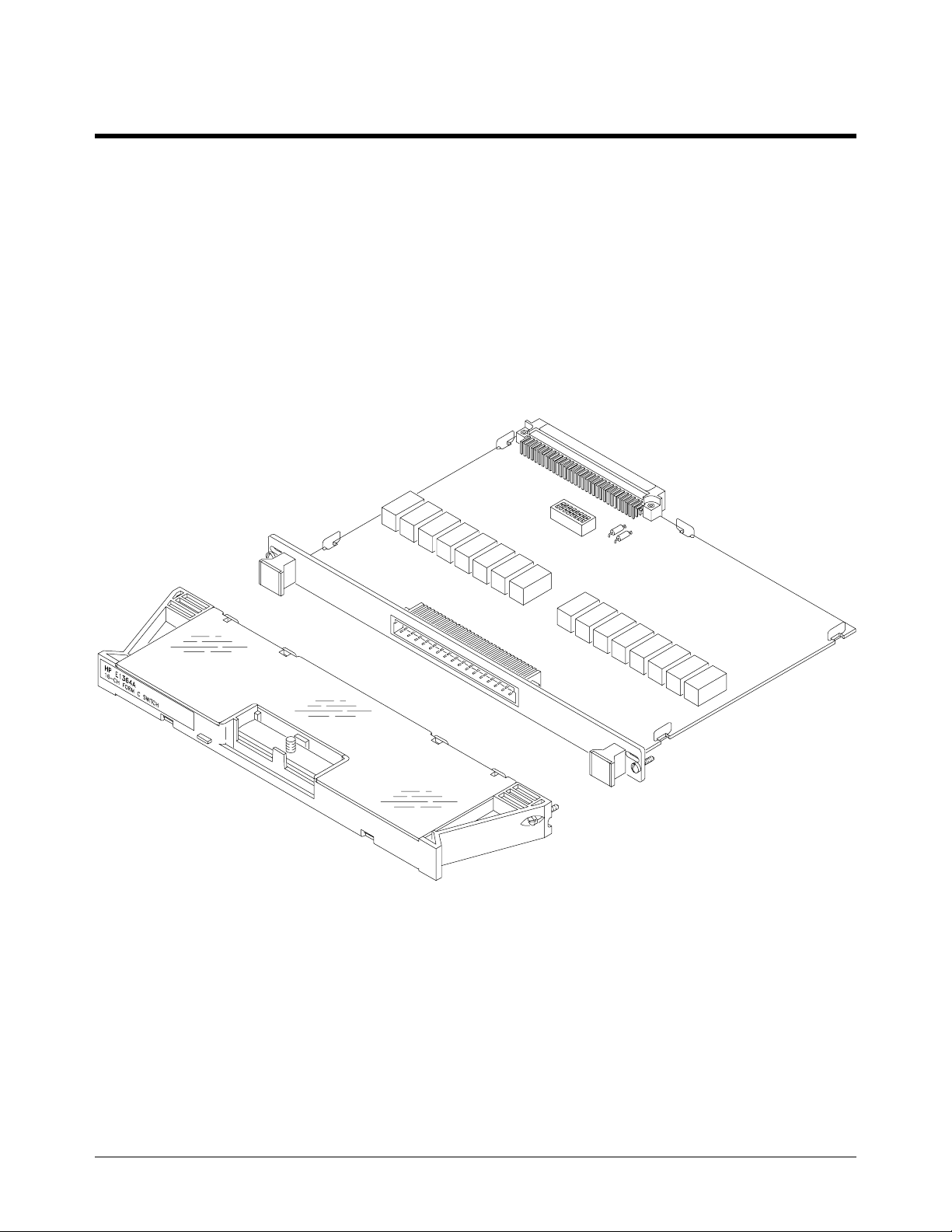
User’s Manual for ad dit ional informa ti on. Fig ur e 1-1 shows the E1364A
Switch Modul e.
Figure 1-1. Agilent E1364A Form C Switch Module
Chapter 1 General Information 11
Page 12

Safety Considerations
This product is a Saf ety Class I instrume nt tha t is provided wit h a prote c ti ve
earth terminal when installed in the mainframe. The mainframe, switch, and
all related documentation should be reviewed for familiarization with safety
markings and i nstructions be f ore operation or serv ice .
Refer to the WARNINGS on page 6 in this manual for a summary of safety
information. Safety information for preventive maintenance, testing, and
service foll ows a nd is also found throughout this ma nual.
WARNINGS and
CAUTIONS
WARNING SERVICE-TRAINED PERSONNEL ONLY. The information in this
This section cont ai ns W AR N INGS which must be followed for your
protection and CAUTIONS whi c h mus t be followed to avoid dama ge to the
equipment whe n pe rforming instrume nt maintena nc e or re pa ir .
manual is for service-trained personnel who are familiar with
electronic circuitry and are aware of the hazards involved. To
avoid personal injury or damage to the instrument, do not
perform procedures in this manual or do any servicing unless
you are qualified to do so.
CHECK MAINFRAME POWER SETTINGS. Before applying
power, verif y th at the mainf r a me se t ti n g ma tc h e s the line
voltage and that the correct fuse is installed. An uninterruptible
safety earth ground must be provided from the main power
source to t he suppl ie d po we r co rd set.
GROUNDING REQUIREMENTS. Interruption of the protective
(grounding) conductor (inside or outside the mainframe) or
disconnecting the protective earth terminal will cause a
potential shock hazard that could result in personal injury.
(Grounding one conductor of a two-conductor outlet is not
sufficient protection.)
IMPAIRED PROTECTION. Whenever it is likely that instrument
protection has been impaired, the mainframe must be made
inoperative and be se cured against any u n intende d op e rat ion.
REMOVE POWER IF POSSIBLE. Some procedures in this
manual may be performed with power supplied to the
mainframe while prote ct ive cove rs are removed. Ene rgy
available at many points may, if contacted, result in personal
injury. (If maintenance can be performed without power applied,
the power should be removed.)
12 General Information Chapter 1
Page 13

WARNING USING AUTOTRANSFORMERS. If the mainframe is to be
energized via an autotransf or mer (for voltage reduction) make
sure the common terminal is connected to neutral (that is, the
grounded side of the main’s supply).
CAPACITOR VOLTAGES. Capacitors inside the mainframe may
remain charged even when the mainframe has been
disconnected from its source of supply.
USE PROPER FUSES. For continued protection against fire
hazard, replace the line fuses only with fuses of the same
current rating and type (such as normal blow, time delay, etc.).
Do not use repaired fuses or short-circuited fuseholders.
CAUTION Static electricity is a maj o r ca u se o f co mp onent fa il u re . T o
preven t damage to t he electrical comp onents in th e switch,
observe anti-static techniques whenever working on the switch.
Chapter 1 General Information 13
Page 14
Inspection/Shipping
This section c ont ai ns initial (i nc omi ng) inspection and shipping guide lines
for the E1364A Switc h Module.
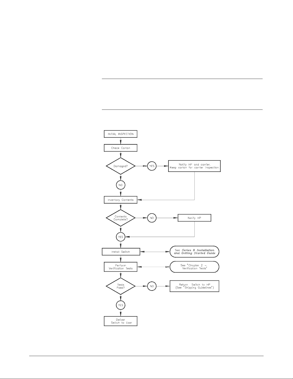
Initial Inspection Use the steps in F igure 1-2 as guidelines to perfor m initial in spe c ti on of the
switch modul e.
WARNING To avoid possible hazardous electrical shock, do not perform
electrical tests if there are signs of shipping damage to the
shipping container or to the instrument.
Figure 1-2. Initial (Incoming) Inspection Guidelines
14 General Information Chapter 1
Page 15
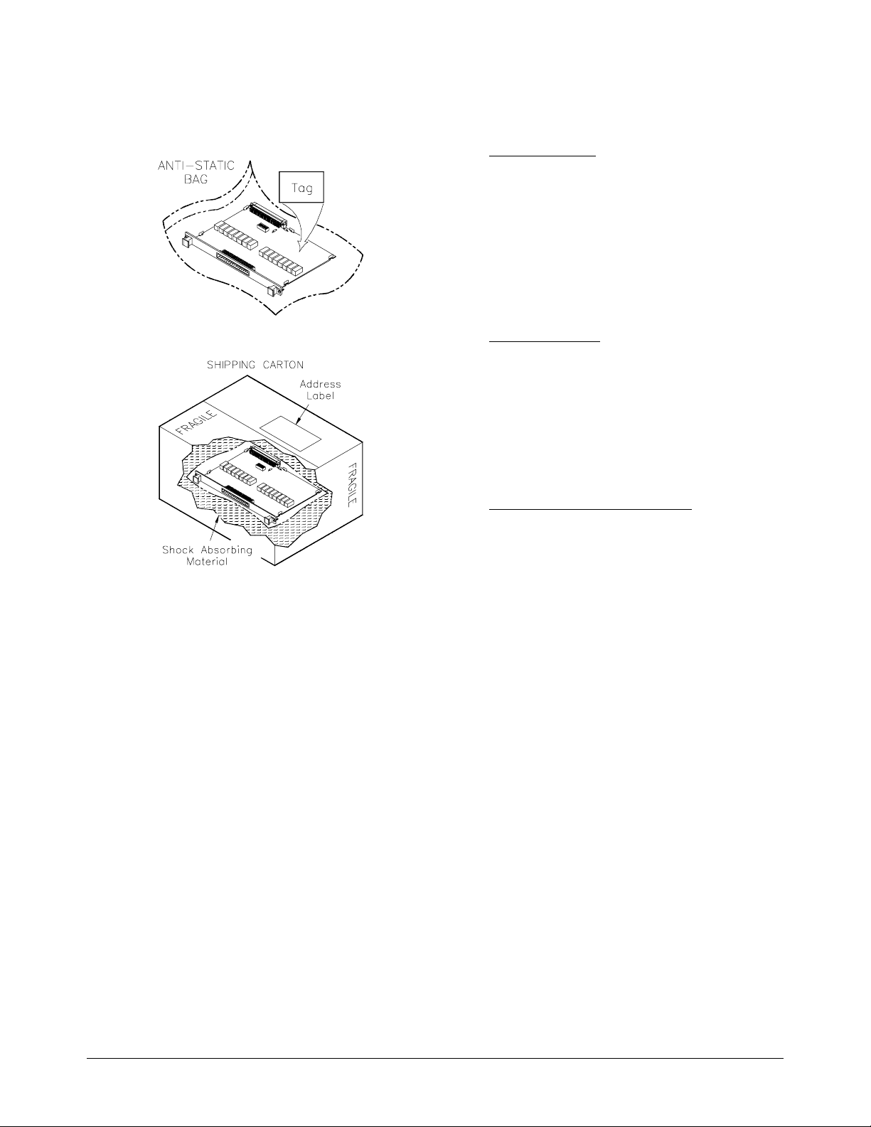
Shipping Guidelines Follow the step s in F igure 1-3 to return the E1364A Switch Mod ule
to an Agilent Te ch nol ogies Sales and Suppor t Office or Serv ic e Ce nte r.
1. Prepare the Switch
• Remove user wiring from termi na l mo dule.
• Attach ta g to switch that identi f ie s :
– Owner
– Model Number/Serial Number
– Service Required
• Place tagged device in approved anti-static
bag.
2.
Pack age the Switc h
• Place packaged switch in shipping carton.*
• Place 75 to 100 mm (3 to 4 inches) of
shock-absorbi ng material around t he
module.
• Seal the shippi ng c ontainer securely.
• Mark the shipping container FRAGILE.
3.
Ship the Switch to Hewlett-Packard
• Place address lab el on shi pping carton.
• Send carton to Agilent Technologies .
* We recommen d tha t you use the sam e sh ipping mater ia ls as t hose use d in factory packa ging (avail ab le from
Agilent). For othe r (commercially available) shippi ng materials, use a double-walled carton with minimum 2. 4
MPa (350 psi) te st .
Figure 1-3. Packaging/Shipping Guidelines
Chapter 1 General Information 15
Page 16

Environment
The recommended operating environment for the E1364A Switch Module
is:
Switch Description
The Agilent E1364A Switch Modu le is a n "instrument " in the slots of a
VXIbus mainframe . As su ch , i t is ass ign ed an er ro r queu e, input and outp ut
buffers, and a status register. The switch has 16 channe ls of Form C relays.
Each channel in cl ude s a rel ay with com mo n (C) , no rma lly open (NO), and
normally close d ( N C) co nta c ts .
Environment Temperature Humidity
Operating 0oC to + 5 5oC <65% relative (0oC to + 4 0oC)
Storage and
Shipment
o
-40
C to +75oC <65% relative (0oC to + 4 0oC)
NOTE Instruments are bas ed o n the logical addre sse s of the plug-in modules. See
Switch
Specifications
Switch Serial
Numbers
Chapter 1 of the E1364A User’s Manual to set the logical address of the
switch mod u le .
Switch module spe ci fic a tions are listed in Appendix A of th e E1364A
User’s Manual. These specifications are the performance standards or limits
against which the instr ument may be tested.
Switches cover e d by this manual a re identifie d by a seri al number prefix
listed on the title page. Agilent uses a two-part serial number in the form
XXXXAYYYYY, where XXXX is the serial prefix, A is the country of
origin (A=USA), and YYYYY is the serial suffix. The serial number prefix
identifi e s a ser ie s of identical instruments. T he se ri a l number suffix is
assigned sequentially to each instrument.
The serial number plate is located on the backplane connector. If the serial
number prefix o f your instrument is gre a te r tha n the one liste d on the title
page, a Manual Upda te (as re quired) will expla in ho w to a da pt this manual
to your instrument.
Switch Options There are no electrical or mechanical options available for the E1364A
Switch Modul e.
16 General Information Chapter 1
Page 17

Recommended Test Equipment
Table 1-1 lists the test equi pme nt recommended f or testing, adju st ing, and
servicing the E1364A Switch Modul e. Essential requirements for each piece
of test equipment are descr ibed in the "Re quirements" c olumn.
Table 1-1. Recomm e nde d Te st Equipment
Instrument Requirements Recommended Model Use*
Controller, GP-IB GP-IB compat ibi lity as defined by
Main fram e Compa tible with switch
Digital Multimeter
IEEE Standard 488-1978 and the
identical ANSI St andard MC1.1:
SH1, AH1, T2, TE0, L2, LE 0, S R0,
RL0, PP0, DC0, D T0, and C1, 2, 3,
4, 5.
Use the E1403 B A/B- to-C- size
Adapter to inst all a B-size module in
a C-size E14XX mainframe.
2-wire ohms (up to 1 GΩ)
4-wi re ohms
* F = Functional Verificat i on, O = O per at ion Verif icat i on Tes ts ,
P = Performance Verificat ion Tests, T = Troubleshoo ting
HP 9000 Series 300
or
IBM compatible PC with HP
BASIC
E1300A, E1301 A,
E1302A (requires E1306A**)
E1400B/T (requir es E1405A/B
or E1406B**),
E1401B/T (requ ires E1405A/B
or E1406B**),
E1421B (requires E1405A/B
or E1406B**)
** or an embedded controller or
VXLink in place of a command
module.
3458A
34401A
F,O,
P,T
F,O,
P,T
O,P,T
Chapter 1 General Information 17
Page 18

Notes
18 General Information Chapter 1
Page 19

Introduction
Chapter 2
Verification Tests
The three levels of test procedures described in this chapter are used to
verify that the E1364A Switch Mo dul e:
• is fully function al (Func tional Verification)
• meets selected testable specifications (Operation Verification)
• meets all testable specifications (Performance Verification)
Test Condit ions
and Procedur es
Performance Test
Record
Verificat ion Test
Examples
See Table 1-1 for te st e quipment requir e me nts. You should com plete the
Performance Verification tests at least once a year. For heavy use or severe
operating environments, pe rform the tests mor e of te n.
The verificati on tests assume tha t the pe rs on pe r form ing the tests
understands ho w to ope r a te the ma i nf rame, the switch, a nd spe c if i ed te st
equipment . The te st pr oc e dure s do not specify equipment settings for test
equipment, except in general terms. It is assumed that a qualified,
service-trained technician will select and connect the cables, adapters, and
probes required f or the te st.
The results of each Performance Verification test may be recorded in
Table 2-1, "Agilen t E1364A Performance Test Recor d. " You may make a
copy of this for m, if de sired.
Each verification test proced ur e inc ludes an example progr a m that performs
the test. All example programs assume the following conf iguration:
• Controller is an HP 9000 Ser ies 200/300 compu ter
• Programming la nguage is BASIC
• Switch address is 7 0915
• Switch card number is 1
• DMM is an 3458A
Chapter 2 Verification Tests 19
Page 20

Functional Verification
The Functiona l Ve rif ica ti on Te st for the E1364A sw it ch con sists of sending
*IDN? command and chec king the respons e. Thi s te st can be used at any
the
time to verify that the switch is connec ted properly and is r e sponding to
basic commands .
Procedure 1. Verify tha t the switc h is installed in the main f ram e a nd t h a t the
mainframe has passed its power-on test.
2. Send the
following).
3. The switch mo dule should retur n the f oll owing string (revision
number may vary):
*IDN? command to t he sw it ch module (see e xa mpl e
HEWLETT-PACKARD,SWITCHBOX,0,A.06.00
NOTE If the pri ma r y ad dr ess se tting, secondary address set ti ng, or interface se le c t
code is set incor rectl y, the switch will not r espond. Verify proper ad dr ess
selection bef or e tro ubleshooting.
Example An exampl e follows which uses an HP 9000 S eri es 300 c omputer with
HP BASIC and a switch addr ess of 70915.
10 DIM A$[80]
20 OUTPUT 70915;"*IDN?" !Send the ID co m mand
30 ENTER 70915;A$ !Get response
40 PRINT A$
50 END
Operation Verification
The procedures in this section are used to provide a high confidence that the
switch module is meeting published specifications. The Operation
Verification tests are a subset of the Performance Verification tests and are
suitable for checkout after performing repairs.
Operation Verification is performed by completing the Closed-Channel
Resistan ce Te st as described in the Performa nce Verific at ion test
procedures. Th is test is usually sufficien t to verify tha t t h e switch module is
meeting its specifications.
20 Verification Tests Chapter 2
Page 21

Performance Verification
The procedures in this section are used to test the switch modul e ’s el ectrical
performance using the specificati ons in Appe ndix A of the E1364A User’s
Manual as the performance standards. These tests are suitable for incoming
inspecti on, tr oubleshooti ng, a nd pr e ve n ti ve ma intenance .
Test Fixture A test fi xture is required for the following t es ts. It is r e co mmended that you
order an extra terminal module (aka "terminal bloc k" ) to use a s a tes t
fixture, so tha t you do not have to re-wire the termina l module each time
these tests a re per f or me d. T he te rminal module pa rt number is
E1364-80001.
Figures 2-1(a) and 2-1(b) show how the test fixt ur e sh ould be wired.
Perform the following steps to wire the test fixture:
– Short all NO (Normally Open) lines t oge ther.
– Short all NC (Normally Cl ose d) lines togethe r .
– Short all C (Common) lin es together.
Figure 2-1(a). Agilent E1364A Test Fixture Schematic
Chapter 2 Verification Tests 21
Page 22

Figure 2-1(b). Agilent E1364A Test Fixture
22 Verification Tests Chapter 2
Page 23

Test 2-1: Closed-Channel Resistance Test
The purpose of this test is to verify that all relay contacts meet the
closed-chann el resi st an ce spe c if i cation for the switch module. If the
closed-c h ann el resist ance of any contact i s greater than 3 .5
should be replaced.
Normally Open
Contacts 1. Hardware Connections
Ω, th e relay
Figure 2-2. Closed-Channel Resistance (NO channels)
2. Equipment Setup
• Set DMM to: 4-wire ohms, au tor a nge .
• Send *RST to the switch to open all NO contacts.
3. Closed-Cha nne l Reading (channe l 00)
• Send CLOS (@100) to the switch to cl ose c ha nne l 00.
• Trigger the DMM and record the reading.
4. Open-Channel Reading (channel 00)
• Send OPEN (@100) to the switch to open c ha nne l 00.
• Trigger the DMM and verify that an open cir c ui t is indicated
5. Closed- and Open -Channel Readings ( c ha nne ls 01- 15)
(>10
8
Ω).
• Repeat steps 3 and 4 fo r channe ls 01 through 15 . Use
CLOS (@ccnn) and OPEN (@ccnn), where
cc
= switch card nu mbe r (0 1- 99, le ad ing zero not necess ary)
nn = channel number (00-15)
Chapter 2 Verification Tests 23
Page 24

Normally Closed
Contacts 1. Hardware Connections
Figure 2-3. Closed-Channel Resistance (NC Channels)
2. Equipment Setup
• Set DMM to: 4-wire ohms, au tor a nge .
• Send *RST to the switch.
• Send CLOS (@100:115) to the switch to open all NC contacts.
3. Closed-Cha nne l Reading (channe l 00)
• Send OPEN (@100) to the switch to close channel 00.
• Trigger the DMM and record the reading.
4. Open-Channel Reading (channel 00)
• Send CLOS (@100) to the switch to ope n ch anne l 00.
• Trigger the DMM and verify that an open cir c ui t is indicated
5. Closed- and Open -Channel Readings ( c ha nne ls 01- 15)
(>10
8
Ω).
• Repeat steps 3 and 4 fo r channe ls 01 through 15 . Use
CLOS (@ccnn) and OPEN (@ccnn), wh ere
cc = switch card number (01-99, leading zero not necessary)
nn = channel number (00-15)
24 Verification Tests Chapter 2
Page 25

Example:
Closed-Channel
Resistance Test
This example performs the Closed-Channel Resistance Test for all
Normally Open and Normally Closed contacts.
10 ! RE-STORE "CONTACT_RES"
20 ASSIGN @Switch TO 70915
30 ASSIGN @Dmm TO 722
40 !
50 OUTPUT @Switch;"*RST" !Open all NO contacts
60 OUTPUT @Dmm;"PRESET NORM;TRIG HOLD"
70 OUTPUT @Dmm;"FUNC OHMF"
80 !
90 !--------------- NORMALLY OPEN C ONT ACT S --------------100 DISP "Connect DMM to NO and C lines of E1364A (4-wire
connection)"
110 PAUSE
120 DISP
130 PRINT "Contact Resistance -- Normally Open Contacts"
140 PRINT
150 !
160 FOR I=0 TO 15
170 !Closed-channel resistance (NO contacts)
180 OUTPUT @Switch;"CLOS (@"&VAL$(100+I)&")"
190 OUTPUT @Dmm;"TRIG SGL"
200 ENTER @Dmm;Rdg
210 PRINT "Channel "&VAL$(I)&" (closed): "&VAL$(Rdg)
220 !
230 !Open-channel resistance (NO contacts)
240 OUTPUT @Switch;"OPEN (@"&VAL$(100+I)&")"
250 OUTPUT @Dmm;"TRIG SGL"
260 ENTER @Dmm;Rdg
270 PRINT "Channel "&VAL$(I)&" (open): "&VAL$(Rdg)
280 PRINT
290 NEXT I
300 !
310 !--------------- NORMALLY CLO SED CONTACT S --- ---- -------320 DISP "Connect DMM to NC and C lines of E1364A (4-wire
connection)"
330 PAUSE
340 DISP
350 PRINT "Contact Resistance -- Normally Closed Contacts"
360 PRINT
370 !
Continued on Next Page
Chapter 2 Verification Tests 25
Page 26

380 OUTPUT @Switch;"CLOS (@100:115)" !Open all NC contact s
390 FOR I=0 TO 15
400 !Closed-channel resistance (NC contacts)
410 OUTPUT @Switch;"OPEN (@"&VAL$(100+I)&")"
420 OUTPUT @Dmm;"TRIG SGL"
430 ENTER @Dmm;Rdg
440 PRINT "Channel "&VAL$(I)&" (closed): "&VAL$(Rdg)
450 !
460 !Open-channel resistance (NC contacts)
470 OUTPUT @Switch;"CLOS (@"&VAL$(100+I)&")"
480 OUTPUT @Dmm;"TRIG SGL"
490 ENTER @Dmm;Rdg
500 PRINT "Channel "&VAL$(I)&" (open): "&VAL$(Rdg)
510 PRINT
520 NEXT I
530 !
540 END
26 Verification Tests Chapter 2
Page 27

Test 2-2: DC Isolation Test
This test ve ri f ie s that sufficie nt DC isolat ion exists betw e e n va ri ous points
on the switch module. The DMM use d should be capa ble of me a sur ing up to
at least 1 G
">R
If the DMM is a 3458A, for exam pl e, the reading shoul d be wri tt e n as ">1. 2
G
Normally Open to
Common 1. Hardware Connections
max
Ω".
", where R
Ω. If the DMM indicates an overload, record the reading as
is the highest resistance that the DMM can measure.
max
Figure 2-4 . D C Is ola tion Test (NO C ha nne ls to Common)
2. Equipment Setup
• Set DMM to: 2-wire ohms, 1 G Ω rang e.
• Send *RST to the switch to open all NO contacts.
3. DC Isolation Reading
• Trigger the DMM and record the reading.
Chapter 2 Verification Tests 27
Page 28

Normally Closed to
Common 1. Hardware Connections
Figure 2-5. DC Isolation Test (NC Channels to Common)
2. Equipment Setup
• Set DMM to: 2-wire ohms, 1 G Ω rang e.
• Send *RST to the switch.
• Send the CLOS (@100:115) command to the switch to open all NC
contacts.
3. DC Isolation Reading
• Trigger the DMM and record the reading.
28 Verification Tests Chapter 2
Page 29

Normally Open to
Chassis 1. Hardware Connections
Figure 2-6. DC Isolation Test (NO Channels to Chassis)
2. Equipment Setup
• Set DMM to: 2-wire ohms, 1 G Ω rang e.
• Send *RST to the switch.
• Send the CLOS (@100:115) command to the switch to close all NO
contacts.
3. DC Isolation Reading
• Trigger the DMM and record the reading.
Chapter 2 Verification Tests 29
Page 30

Normally Closed to
Chassis 1. Hardware Connections
Figure 2-7. DC Isolation Test (NC Channels to Chassis)
2. Equipment Setup
• Set DMM to: 2-wire ohms, 1 G Ω rang e.
• Send *RST to the switch to close all NC contacts.
3. DC Isolation Reading
• Trigger the DMM and record the reading.
30 Verification Tests Chapter 2
Page 31

Example: DC
Isolation Test
This example performs the DC Isolation Test for Normally Open and
Normally Closed channels to both Common and chassis (earth ground).
10 !RE-STORE "DC_ ISOL"
20 ASSIGN @Switch TO 70915
30 ASSIGN @Dmm TO 722
40 !
50 OUTPUT @Dmm;"PRESET NORM;TRIG HOLD"
60 OUTPUT @Dmm;"FUNC OHM;RANGE 1E9"
70 !
80 !---------------NORMALLY OPEN TO COM MO N -- ------------90 DISP "Connect DMM HI and LO to E1364A NO and C lines"
100 PAUSE
110 DISP
120 !
130 OUTPUT @Switch;"*RST" !Open all NO contacts
140 WAIT 1
150 OUTPUT @Dmm;"TRIG SGL"
160 ENTER @Dmm;Rdg
170 !
180 PRINT "DC Isolation -- Normally Open Channels to Common"
190 PRINT "R = "&VAL$(Rdg)
200 PRINT
210 !
220 !---------------NORMALLY CLOSED TO COMMON--------------230 DISP "Connect DMM HI and LO to E1364A NC and C lines"
240 PAUSE
250 DISP
260 !
270 OUTPUT @Switch;"CLOS (@100:115)" !Open all NC contacts
280 WAIT 1
290 OUTPUT @Dmm;"TRIG SGL"
300 ENTER @Dmm;Rdg
310 !
320 PRINT "DC Isolation -- Normally Closed Channels to Common"
330 PRINT "R = "&VAL$(Rdg)
340 PRINT
350 !
360 !---------------NORMALLY OPEN TO CHASSIS--------------370 DISP "Connect DMM HI and LO to E1364A NO line and mainframe
chassis"
380 PAUSE
390 DISP
400 !
Continued on Next Page
Chapter 2 Verification Tests 31
Page 32

410 OUTPUT @Dmm;"TRIG SGL"
420 ENTER @Dmm;Rdg
430 !
440 PRINT "DC Isolation -- Normally Open Channels to Chassis"
450 PRINT "R = "&VAL$(Rdg)
460 PRINT
470 !
480 !---------------NORMALLY CLOSED TO CHASSIS--------------490 DISP "Connect DMM HI and LO to E1364A NC line and mainframe
chassis"
500 PAUSE
510 DISP
520 !
530 OUTPUT @Switch;"OPEN (@100:115)" !Close all NC contacts
540 WAIT 1
550 OUTPUT @Dmm;"TRIG SGL"
560 ENTER @Dmm;Rdg
570 !
580 PRINT "DC Isolation -- Normally Closed Channels to Chassis"
590 PRINT "R = "&VAL$(Rdg)
600 !
610 END
32 Verification Tests Chapter 2
Page 33

Performance Test Record
Table 2-1, "Performance Test Reco rd for th e E1 364A S w it ch Module," is a
form you may copy a nd use to record performan ce ve rif ica tion test result s
for the switch module. Pages 3 and 4 of Table 2-1 show switch accuracy,
measurement uncertainty (M.U.), and test accuracy ratio (TAR) values.
Switch Accuracy Accuracy is defined for closed-channel contact resistance and DC isolation
using the specific a ti ons in Appendix A of the E136 4A Use r’s Manual. The
closed-chann el resi stance and DC isolat ion specificati ons are single-sided,
meaning th at the r e is an uppe r limit OR a lower limit, but not both. In Table
2-1, either the "Minim um" or "Ma ximum" col umn will be blank fo r a
single-side d te st.
Measurement
Uncertainty
Closed-Channel
For the performance verification tests in this manual, the measurement
uncertainties are based on 90-day accuracy specifications for the 3458A
Digital Multimeter. The calculations are shown below.
Conditions:
Resistance Test
– 4-wire ohms function
– 10 Ω range
– 90- da y spec ifi cat ion s
– Worst-case reading = 3.5 Ω
M.U. = 15ppm of Reading + 5ppm of Range
= 15 x 10
= 1.03 x 10
-6
DC Isolation Test Conditions:
– 2-wire ohms function
– 1 GΩ range
– 90- da y spec ifi cat ion s
– Worst-case reading = 1.2 GΩ (highest resistance that can be
measured with the 3458A)
⋅ 3.5 + 5 x 10-6 ⋅ 10 (Ω)
-4
Ω
Test Accuracy
Ratio (TAR)
M.U. = 0.5% of Readin g + 10ppm of Ran ge
= 0.005 ⋅ 1.2 x 10
= 6 x 10
Test Accuracy Ra tios are not define d for single-sided meas ur em e nts, so all
closed-channel resi st an ce a nd DC i sol ation measurements have "NA" (Not
Applicable) in the TAR column.
6
Ω
9
+ 10 x 10-6 ⋅ 1 x 109 (Ω)
Chapter 2 Verification Tests 33
Page 34

Table 2-1. Performance Test Record for the E1364A Swit ch Mod ul e (Page 1 of 4)
Test Facility:
Name______ ________________________ ________
Address____________________________ ________
City/State___________________________________
Phone______________________________________
Model _______ ____ ____________ ____ __________
Serial No.________ _________________________
Options____________________________________
Firmware Rev.___ ___________________________
Special Note s:
____________________________________________________________________________________________
____________________________________________________________________________________________
____________________________________________________________________________________________
____________________________________________________________________________________________
Report No.____ ______________________________
Date__________________ ____________________
Customer___ ____________ ____________ _______
Tested by_______ ___________________________
Ambient tempera tu re_ ____ __________________
Relative humidit y___________________________%
Line frequency__ ____________ ____ _________ Hz
(nominal)
o
C
____________________________________________________________________________________________
____________________________________________________________________________________________
____________________________________________________________________________________________
____________________________________________________________________________________________
____________________________________________________________________________________________
____________________________________________________________________________________________
____________________________________________________________________________________________
____________________________________________________________________________________________
____________________________________________________________________________________________
____________________________________________________________________________________________
____________________________________________________________________________________________
____________________________________________________________________________________________
____________________________________________________________________________________________
34 Verification Tests Chapter 2
Page 35

Table 2-1. Performance Test Record for the E1364A Switch Module (Page 2 of 4)
Model ________ ____ ____________ ____ __ Report No. ____________________ Date _________________
Test Equipment U sed :
Description Model No. Trace No. Cal Due Date
1. _______________________________
2. _______________________________
3. _______________________________
4. _______________________________
5. _______________________________
6. _______________________________
7. _______________________________
8. _______________________________
9.________________________________
10._______________________________
11._______________________________
12._______________________________
13._______________________________
14._______________________________
15._______________________________
16._______________________________
______________
______________
______________
______________
______________
______________
______________
______________
______________
______________
______________
______________
______________
______________
______________
______________
______________
______________
______________
______________
______________
______________
______________
______________
______________
______________
______________
______________
______________
______________
______________
______________
______________
______________
______________
______________
______________
______________
______________
______________
______________
______________
______________
______________
______________
______________
______________
______________
17._______________________________
18._______________________________
19._______________________________
20._______________________________
______________
______________
______________
______________
______________
______________
______________
______________
______________
______________
______________
______________
Chapter 2 Verification Tests 35
Page 36

Table 2-1. Performance Test Record for the E1364A Swit ch Mod ul e (Page 3 of 4)
Model ______ ____ ____________ ____ ____ Report No. _____________________________ Date_____________
Test
No.
2-1. Closed-Channel Resistance Test (Values in ohms)
Test
Description Minimum*
Measured
Reading Maximum
Normally Open (NO) Contacts
Channel 00
Channel 01
Channel 02
Channel 03
Channel 04
Channel 05
Channel 06
Channel 07
Channel 08
Channel 09
Channel 10
Channel 11
Channel 12
Channel 13
Channel 14
Channel 15
____________
____________
____________
____________
____________
____________
____________
____________
____________
____________
____________
____________
____________
____________
____________
____________
Normally Closed (NC) Contacts
Channel 00
Channel 01
Channel 02
Channel 03
Channel 04
Channel 05
Channel 06
Channel 07
Channel 08
Channel 09
Channel 10
Channel 11
Channel 12
Channel 13
Channel 14
Channel 15
____________
____________
____________
____________
____________
____________
____________
____________
____________
____________
____________
____________
____________
____________
____________
____________
3.5
3.5
3.5
3.5
3.5
3.5
3.5
3.5
3.5
3.5
3.5
3.5
3.5
3.5
3.5
3.5
3.5
3.5
3.5
3.5
3.5
3.5
3.5
3.5
3.5
3.5
3.5
3.5
3.5
3.5
3.5
3.5
Meas
Uncert TAR
1.03E-4
1.03E-4
1.03E-4
1.03E-4
1.03E-4
1.03E-4
1.03E-4
1.03E-4
1.03E-4
1.03E-4
1.03E-4
1.03E-4
1.03E-4
1.03E-4
1.03E-4
1.03E-4
1.03E-4
1.03E-4
1.03E-4
1.03E-4
1.03E-4
1.03E-4
1.03E-4
1.03E-4
1.03E-4
1.03E-4
1.03E-4
1.03E-4
1.03E-4
1.03E-4
1.03E-4
1.03E-4
NA
NA
NA
NA
NA
NA
NA
NA
NA
NA
NA
NA
NA
NA
NA
NA
NA
NA
NA
NA
NA
NA
NA
NA
NA
NA
NA
NA
NA
NA
NA
NA
*Single-si de d spe c if ica tion -- Minimu m doe s not apply.
36 Verification Tests Chapter 2
Page 37

Table 2-1. Performance Test Record for the E1364A Swit ch Mod ul e (Page 4 of 4)
Model ____________________________ Report No. _____________________ Date______________
Test
No.
2-3. DC Isolation Test (Values in ohms)
Test
Description Minimum
NO to Common
NC to Common
NO to chassis
NC to chassis
1E8
1E8
1E8
1E8
____________
____________
____________
____________
*Single-si de d spe c if ica tion -- Maximum does not apply.
Measured
Reading Maximum*
Meas
Uncert TAR
6.0E6
6.0E6
6.0E6
6.0E6
NA
NA
NA
NA
Chapter 2 Verification Tests 37
Page 38

Notes
38 Verification Tests Chapter 2
Page 39

Introduction
Chapter 3
Replaceable Parts
This chapter contains information for ordering replaceable parts for the
E1364A Switch Modules with serial num be r 2934A10370 and higher.
The tables provide the following informat ion:
• Table 3-1 list s as se mbly and termina l module part nu mbers for the
E1364A Switch Module.
• Table 3-2 list s the Ref e rence Des ignators for the switch module.
Ordering
Information
To order a part list ed in Table 3-1, speci fy the Agilent part numbe r an d the
quantity req uir e d. Send the order to your near e st Agi le nt Te ch nologies
Sales and Support Office.
If your E1364A Switch Module has a serial numbe r prior to 2934A10370,
see Appendix B, "B ackdating Info rma ti on, " f or repl a cea bl e par ts
information.
Replaceable Parts Lists
See the Parts Locat or Dia gra ms ( Fi gur e s 3-1 a nd 3- 2) fo r lo cat ions of
replaceable parts.
Table 3-1. E1364A Replaceable Parts (serial number 2934A10370 and higher)
Reference
Designator
BRK1-BRK2
F1
F2
J1
LBL1
LBL2
Part
Number
E1364-66201 1 COMPONENT ASSEMBLY
0050-2183
2110-0936
2110-0936
1252-1591
E1300-84308
E1300-84312
Qty Part Description
2
1
1
1
1
1
BRKT-PNL MNT
FUSE 4A 125V SMT
FUSE 4A 125V SMT
CONNECTOR-RA PL, 48P
LBL LOGO B SIZE
LBL-LOGO VXI B SIZE
RELAY-ARMATURE HiR, Low E
K100-K115
MP1-2
P1
SCR1-2
SCR3-4
SHD1
SW1
0490-1912
1400-1546
1252-1596
0515-0444
0515-1968
E1300-80601
3101-3142
E1364-80001 1 TERMINAL MODUL E
E1364-66510
E1300-8440111
16
BRACKET PC BOARD HOLDER; BLACK; EXTRUDED
2
CONNECTOR-POST TYPE 2.54-PIN-SPCG 96-CONTACT
1
SCREW- X 8MM-LG -HD
2
SCR PHM 2.5 X 11 TX
2
SHIELD SAFETY
1
SWITCH-DIP 8 - 1A SMTV
1
TERMINAL CARD 16-CH GP RLY SWITCH
TERMINAL CARD, CASE ASSY
Chapter 3 Replaceable Parts 39
Page 40

Table 3-2. Reference Designa tors
A assembly PCB printed circuit boar d
BRK bracket PNL panel
C capacitor R resistor
CR diode RP resistor pack
LBL label RVT rivet
Ffuse SCRscrew
J electrical connector (jack) SHD shield
JM jumper SW switch
K rel ay T B terminal block (module)
MP mechanical part U integ rated circuit
P electrical connector (plug)
Figure 3-1. E1364A Mechanical Replaceable Parts
40 Replaceable Parts Chapter 3
Page 41

Figure 3-2. E1364A Terminal Block Replaceable Parts
Chapter 3 Replaceable Parts 41
Page 42

Notes
42 Replaceable Parts Chapter 3
Page 43

Introduction
WARNING Do not perform any of the service procedures shown unless
Chapter 4
Service
This chapter contains service information for the Agilent E1364A Switch
Module, including trou ble shooting tech niques and repai r and m ai ntenance
guidelines.
you are a qu a li f ied, serv ic e- t rained te ch nicia n, and have r ea d
the WARNINGS and CAUTIONS in Chapter 1.
Equipment
Required
Equipment r e qui red f or switch trouble shooting and re pa ir is listed in
Table 1-1, "Reco mm en de d Te st Equipment ." Any eq uipment that sat isfies
the requirem en ts given in the ta bl e m ay be su bstituted. To a void damage to
the screw head slots, use a T8 Torx drive r to r emove the front panel ha ndl es .
Service Aids See Chapter 3, "Replaceable Parts," or Appendix B, "Backdati ng
Information," for descriptions and locations of E1364A replaceable parts,
depending on the serial number of your switch module. Schematic
Diagrams are available at the back of this manual. Service notes, manual
updates, and service literature for the switc h ma y be av ai la ble through
Agilent. For infor ma t ion, contact your ne a rest Agilent Techno logies Sales
and Support Office.
Chapter 4 Service 43
Page 44

Troubleshooting Techniques
To troubleshoot an E 1364A Switch Module pr obl em , you should first
identify the problem and then isolate the cause to a replaceable part. See
Chapter 3, "Replaceable Parts," or Appendix B, "Bac kda ting Information,"
for descriptions and locations of replaceable parts, depending on the serial
number of your switch module.
Identi fy in g th e
Problem
Problem Type Symptom Possible Solutions
Operator Errors Non-zero error co de in res ponse to
Catastrophic
Failures
Performance
Out of
Specification
Table 4-1 lists some common problems, along with symptoms and possible
solutions. If the pr oblem persists, pe rform component-le ve l troubleshoo ting
using the component locator and schematics.
Table 4-1. Agilent E1364A Tests/Checks
the SYST:ERR? command.
Switch not responding to commands. Check logical address setting.
Switch failin g Clo sed- cha nnel
Resistance Test (Test 2-1).
See Appendix C of the
E1364A User’ s M anual for Switch
errors and causes.
See Appendix B of the
E1300A/E1301A or E130 2A U se r’ s
Manual for addi tion al
information on opera to r errors.
See "Testing the Ass em bly" in this
chapter.
Check user wiring and test
connections.
Replace relays that correspond to
the channels that are fail ing. For
example, if channe l 15 fails, rep lace
relay K115.
If most of the chann els are near
or above the test limit (3.5 Ω),
replace the entire module (part
number E1364-66 201).
Switch failing DC Isolation Test
(Test 2-2).
Check user wiring and test
connections.
Clean the printed ci rcuit board.
44 Service Chapter 4
Page 45

Testing the
Assembly
You can use the tests and checks in Table 4-2 to isolate the problem. See
Figure 3-1 in Cha pte r 3 or Figur e B-1 in Appendix B for locati ons of
replaceable p art s, dep ending on the ser ia l n umber of your switch module.
Table 4-2. E1364A Tests/Checks
Test/Check Reference Designator Check:
Heat Damage - - - - - - - - - - Discolored PC boards
Switch/Jumper
Settings
Switch PCA F1, F2
JM13, JM14 , ..., JM 26
SP1
P1, J1
K100, K101, ..., K115
Damaged insulation
Evidence of arci ng
IRQ Level setting
LADDR setting
Fuse continu ity
Connector cont acts
Relay contact resistance
Checking for Heat Damage
Inspect the switch for signs of a bnormal intern ally generated he a t such as
discolored printed circui t boa r ds or c omponents, dam a ge d insulation , or
evidence of arc in g . If ther e is dama ge , do not operate the switch until you
have correcte d the problem.
Checking Switch es /Jum pers
Verify that the logical addre ss se tt ing is set corre ct ly (factory set a t 120).
Verify that the interrupt priority jumpers are set correctly (factory set at
level 1). See the E1364A User’s Manual for information.
Checking the Switch PCA
Use the replaceable parts locator (Figure 3-1 or B-1, depending on the
serial number of your sw it c h module) to che c k the f ollowing:
• Verify that fuses F1 and F2 are go od.
• Check the closed-channel resistance of all relays using the procedure
in Chapter 2. Replace any bad relays.
• Check connecto rs P1 and J1 f or da ma ge .
NOTE If the preceding steps fail to isolate the problem, use the schematics
included with this manual to perform compone nt-level tro ubl es hooting.
Chapter 4 Service 45
Page 46

Repair and Maintenance Guidelines
This section provides guidelines for repairi ng a nd ma intainin g the E1364A
Switch Modul e, including:
• ESD precautions
• Solderin g pr inted circuit boards
• Post-repair sa fet y ch ecks
ESD Precautions Electrostatic discharge (ESD) ma y da m ag e st a tic sensitive de vices in the
E1364A Switch Mo dule. This damage c an range fro m sl ight parameter
degradation to catastrophi c failure. When handling switch a sse mblies,
follow th es e gu ide lines to av oid damagin g sw itch compo ne nts:
• Always use a static-free work station with a pad of
conducti ve rub be r or si milar materia l whe n ha ndling
switch components.
• If a device requir e s sol d e ring, be sur e the as se mbly is
placed on a pad of conduc tive material . Also, be sur e that
you, the pad, and the soldering iron ti p are grounded to
the assembly.
Solde rin g Pr in te d
Circuit Boards
Post-Repair
Safety Checks
Some of the components on the etched circuit boards in the switch have
plated throu gh- holes that allow a sol de r path to both side s of the insulatin g
material. Sol de ring c a n be done from ei ther side of the boa rd with equ al ly
good result s. Wh en soldering to any ci rcuit board, kee p in mind the
following gui de li ne s:
• Avoid unnecessary component unsoldering and soldering.
Excessive replacement can result in damage to the circuit
board and/or ad ja c en t c omponents.
• Do not use a high-power sol de ring iron on etched circ ui t
boards, as exces sive heat may lift a conductor or damage
the board.
• Use a suction devic e or woode n toothpick t o rem ove
solder from co mponent mount ing holes. When using a
suction de vic e , be sure that the equipment is properly
grounded.
After making repa i rs to the E1364A Switch Module, inspect t he sw it ch for
any signs of abnormal internal ly generated hea t, suc h a s discolored pri nte d
circuit boar ds or co mponents, dam aged insulation, or evidenc e of arcing.
Determine and correct the cause of the condition. Then per fo rm the
Functional Ve r ific a ti on Te st described in Cha pter 2 to verify tha t t he switch
is function a l.
46 Service Chapter 4
Page 47

Verification Tests - C Programs
Functional Verification Test
This program is designed to do the Fun ct io na l Ve rif ica ti on Te st found in
Chapter 2, "Verifi cation Tests. "
Example This example sends a *IDN? command to the switch. This test can be used
to verify tha t t he sw it ch is c onne c te d pr operly and is re sponding to a basic
command.
#include <stdio.h>
#include <sicl.h>
Appe ndix A
#define ADDR "hpib7,9,15" /* Address of device */
main ()
{
INST id; /* Define id as an instrum e nt */
char a[256] = {0}; /* Result variabl e */
id = iopen (ADDR); /* Open instrument session */
ipromptf(id, "*IDN?\n", "%t", a); /* Self test com mand */
printf("\n %s", a); /* Print resul t * /
getchar(); /* Pause */
iclose (id); /* Close instrument session */
}
Appendix A Example C Programs 47
Page 48

Performance Verification Tests
These programs are designed to do the Performance Verification Tests
found in Chapte r 2, " V eri fi c ation Tests."
Example:
Closed Channel
Resistance Test
This example performs the Closed-Channel Resistance Test for all
Normally Open and Normally Closed contacts.
/* Closed-channel Resistance Test E1364A */
#include <stdio.h>
#include <sicl.h>
#define ADDR "hpib7,9,15"
#define DMM "hpib7,22"
void main (void)
{
INST id, dm;
char reading[256] = {0}; /* Resu lt variable */
int channel, i;
/* Define id and dm as an instrument */
/* Address of devi c e */
#if defined(__BORLANDC__) && !defined(__WIN32__)
_InitEa syWin() ;
#endif
ionerror(I_ERROR_EXIT);
id = iopen (ADDR);
dm = iopen (DMM);
iprintf (id, "*RST\n");
iprintf (dm, "PRESET NORM;TRIG HOLD\n");
iprintf (dm, "FUNC OHMF\n");
printf ("\n\nConnect DMM to NO and C lines of E1364A (4-wire
connection)");
getchar ();
printf ("\n\nContact Resistance -- Normally open contacts\n");
for (i = 0; i <= 15; i++)
{
channel = 100 + i;
/* Open instrument session */
48 Example C Programs Appendix A
Page 49

iprintf (id, "CLOS (@%u)\n", channel);
ipromptf (dm, "TRIG SGL\n", "%t", reading);
printf ("\n Channel %u (closed): %s", i, reading);
iprintf (id, "OPEN (@%u)\n", channel);
ipromptf (dm, "TRIG SGL\n", "%t", reading);
printf ("\n Channel %u (open): %s", i, reading);
}
printf ("\n\nConnect DMM to NC and C lines of E1364A (4-wire
connection)");
getchar ();
iprintf (id, "CLOS (@100:115)\n");
printf ("\n\nContact Resistance -- Normally closed contacts\n");
for (i = 0; i <=15; i++)
{
channel = 100 + i;
iprintf (id, "OPEN (@%u)\n", channel);
ipromptf (dm, "TRIG SGL\n", "%t", reading);
printf ("\n Channel %u (closed): %s", i, reading);
iprintf (id, "CLOS (@%u)\n", channel);
ipromptf (dm, "TRIG SGL\n", "%t", reading);
printf ("\n Channel %u (open): %s", i, reading);
}
iclose (id);iclose (dm);
}
/* Close instrument session */
Appendix A Example C Programs 49
Page 50

Example: DC
Isolation Test
This example performs the DC Isolation Test for Normally Open and
Normally Closed channels to both Common and chassis (earth ground).
/* DC Isolation Test E1364A */
#include <stdio.h>
#include <sicl.h>
#define ADDR "hpib7,9,15"
#define DMM "hpib7,22"
void main (void)
{
INST id, dm;
char reading[256] = {0}; /* Result va riable */
int channel, i;
#if defined(__BORLANDC__) && !defined(__WIN32__)
_InitEasyWin();
#endif
ionerror(I_ERROR_EXIT);
id = iopen (ADDR);
dm = iopen (DMM);
iprintf (dm, "PRESET NORM;TRIG HOLD\n");
iprintf (dm, "FUNC OHM;RANGE 1E9\n");
printf ("\n\nConnect DMM HI and LO to E1364A NO and C lines");
getchar ();
iprintf (id, "*RST\n");
ipromptf (id, "*OPC?\n", "%t", reading);
ipromptf (dm, "TRIG SGL\n", "%t", reading);
printf ("\nDC Isolation -- Normally Open Channels to Common");
printf ("\n R = %s", reading);
/* Define id and dm as an instrument */
/* Address of device */
/* Open instrument session */
printf ("\n\nConnect DMM HI and LO to E1364A NC and C lines");
getchar ();
iprintf (id, "CLOS (@100:115)\n");
ipromptf (id, "*OPC?\n", "%t", reading);
ipromptf (dm, "TRIG:SGL\n", "%t", reading);
printf ("\nDC Isolation -- Normally Closed Channels to Common");
printf ("\n R = %s", reading);
50 Example C Programs Appendix A
Page 51

printf ("\n\nConnect DMM HI and LO to E1364A NO line and
mainframe chassis");
getchar ();
ipromptf (dm, "TRIG SGL\n", "%t", reading);
printf ("\nDC Isolation -- Normally Open Channels to Chassis");
printf ("\n R = %s", reading);
printf ("\n\nConnect DMM HI and LO to E1364A NC line and
mainframe chassis");
getchar ();
iprintf (id, "OPEN (@100:115)\n");
ipromptf (id, "*OPC?\n", "%t", reading);
ipromptf (dm, "TRIG SGL\n", "%t", reading);
printf ("\nDC Isolation -- Normally Closed Channels to Chassis");
printf ("\n R = %s", reading);
iclose (id);
iclose (dm);
}
/* Close instrume nt session */
Appendix A Example C Programs 51
Page 52

Notes
52 Example C Programs Appendix A
Page 53

Introduction
Appendix B
Backdating Information
This chapter contains information for ordering replaceable parts for the
Agilent E1364A Switch Modules wit h seri al numbers prior to 2934A10370.
• Table B-1 lists the assembly and termin al module part numbe r s fo r
the E1364A Swit ch Module.
• Table B-2 list s the Reference De signators for the switch mo dule.
Ordering
Information
To order a part liste d in Ta ble B-1, specify the Agilent part number and the
quantity req uir e d. Send the order to your ne arest Agilent Tec hnologies Sales
and Support Office.
If your E1364A Swit c h Module has a serial number of 2934A1037 0 an d
higher, refer to Chapter 3 for replaceable parts ordering information.
Replaceable Parts List
See Figures B-1 and B-2 or the Component Lo c ator (in the back of this
manual) for locations of replaceable parts.
Table B-1. Agilent E1364A Replaceable Parts
Reference
Designator
BRK1-BRK2
F1
F2
J1
K0-K15
LBL1
LBL2
Part
Number
E1364-66201 1 COMPONENT ASSEMBLY
0050-2183
2110-0712
2110-0665
1252-1591
0490-1651
E1300-84308
E1300-84312
Qty Part Description
2
1
1
1
16
1
1
PRIMARY COMPONENTS
CASTING-ZN P.C. BOARD HOLDER
FUSE- SUBMINIATURE 4A 125V NTD AX
FUSE- SUBMINIATURE 1A 125V NTD AX UL CSA
CONNECTOR-POST TYPE 5.08-PIN-SPCG 48-CONTACT
RELAY 2C 12VD C-CO IL 3A 220 V DC
LBL LOGO B SIZE
LBL-LOGO VXI B SIZE
MP1-2
P1
SCR1-2
SCR3-4
SHD1
SW1
1400-1546
1252-1596
0515-0444
0515-1968
E1300-80601
3101-3066
2
BRACKET PC BOARD HOLDER; BLACK; EXTRUDED
1
CONNECTOR-POST TYPE 2.54-PIN-SPCG 96-CONTACT
2
SCREW- X 8MM-LG -HD
2
SCR PHM 2.5 X 11 TX
1
SHIELD SAFETY
1
SWITCH-DIP ROCKER 8-1A 0.15A 30VDC
Appendix B Backdating Information 53
Page 54

Reference
Designator
C1 0180-3 899 1 CAPACITOR-FXD 220uF +-2 0% 50 V AL-ELCT LT
C2 0160-3 334 2 CAPACITOR-FXD 0.01uF +-10% 50 V CER X7R
C9 0160-4 801 1 CAPACITOR-FXD 100p F +-5 % 100 V CER C0G
C11 0160-3334 CAPACITOR-FXD 0.01uF +-10% 50 V CER X7R
C17 0160-4835 10 CAPACITOR-FXD 0.1uF +-10% 50 V CER X7R
C38-C42 0160-4835 CAPACITOR-FXD 0.1uF +-10% 50 V CER X7R
C44 0180-1746 1 CAPACITOR-FXD 15uF +-10% 20 V TA
C45-C48 0160-4835 CAPACITOR-FXD 0.1uF +-10% 50 V CER X7R
CR1 1902-0557 1 DIODE-ZENER 24V 5% PD=1W IR=5UA
CR2 1901-1098 1 DIODE-SWITCHI NG 1N4150 50V 200MA 4NS
JM15-JM16 7175-0057 2 RESISTOR 0 MFS
LBL1 7121-7148 1 LABEL-INFORMATION .25-IN-WD .9-IN-LG
LBL2 9320-5333 1 LBL-LNE-PTR; .625- IN- W D X .25- IN -LG
PNL1 E1364-00202 1 PNL-RR RLY MUXR
R1 075 7-0 465 1 RESISTOR 100K +-1% . 125W TF TC = 0+- 100
R2 075 7-0453 1 RESISTOR 30.1K +- 1% .125W TF TC=0+-100
R9 075 7-0 417 1 RESISTOR 562 +-1% .125W TF TC=0+-100
R10 0698-3451 1 RESISTOR 133K +-1% .125W TF TC=0+-100
RP1-RP4 1810-0265 4 NETWORK-RES 16-DIP 680 .0 OHM X 8
RP25-RP26 1810-0279 3 NETWORK-RES 10-SI P 4. 7K O HM X 9
RP32 1810-0279 NETWO R K- RE S 10-SIP 4. 7K O HM X 9
RVT1-RVT2 0361-1231 2 RIVET-SEMITUB OVH .099D I A . 36LG
RVT3-RVT4 0361-1294 2 RIVET-SEMITUB OVH .099D I A . 328L G
RVT5-RVT6 0361-1295 2 RIVET-SEMITUB OVH .095D I A . 406L G
U1-U4 1858-0069 4 TRANSISTOR ARRAY 18-PIN PLASTIC DIP
U5 1820-4057 1 IC BUFFER TTL/F NAND QUAD 2-INP
U6 182 0-6 731 1 IC GATE-ARRAY CM O S
U7-U8 1820-3079 2 IC DCDR CMOS/74HC BIN 3-TO-8-LINE
U9 1820-3081 1 IC FF CMOS/74HC D-TYPE POS-EDGE-TRIG
U10-U11 1820-3975 2 IC DRIVER CMOS/74HC LINE OCTL
U12 1820-4590 1 IC MV CMOS/74HC MONOSTBL RETRIG DUAL
U15 1820-4147 1 IC LCH CMOS/74HCT TRANSPARENT OCTL
U16 1820-3714 2 IC TRANSCEIVER TTL/ALS BUS OCTL
U17-U18 1820-3631 2 IC COMPARATOR CMOS/74HCT MAGTD 8-BIT
U19 1820-3664 1 IC GATE CMOS/HCT NAND QUAD 2-INP
U20 1820-4242 1 IC SCHMITT-TRIG CMOS/74HCT INV HEX
U21-U22 1820-4643 2 IC GATE CMOS/74HCT NOR QUAD 2-INP
Part
Qty Part Description
Number
ADDITIONAL COMPONENTS
3050-0082 2 WASHER-FL NM NO. 4 .1 16- IN-I D .18 8-IN- O D
54 Backdating Information Appendix B
Page 55

Reference
Designator
U25-U26 1820-5424 2 IC DRIVER CMOS/74HCT LINE OCTL
U30 1820-4152 2 IC FF CMOS/74HCT D-TYPE POS-EDGE-TRIG
U35 1820-3714 IC TRANSCEIVER TTL/ALS BUS OCTL
U38 1820-4152 IC FF CMOS/74HCT D-TYPE POS-EDGE-TRIG
Part
Qty Part Description
Number
E1364-80001 1 E1364A TERMINAL MODULE
E1364-66510 1 TERMINAL C ARD 16- CH GP RLY S W I TCH
E1300-84401 1 TERMINAL CARD, CASE ASSEMBLY
Table 3-2. E1364A Re ferenc e Desi gna tors
Agilent E1364A Reference Designators
A assembly P electrical connector (plug)
BRK bracket PCB printed circuit board
C capacitor PNL panel
CR diode R resistor
LBL label RP resistor pack
F fuse RVT rivet
J electrical connector (jack) SCR screw
JM jumper SHD shield
K relay SW switch
LBL label TB terminal block
MP mechanical part U integrated circuit
Appendix B Backdating Information 55
Page 56

Figure B-1. E1364A Component Assembly Parts
56 Backdating Information Appendix B
Page 57

Figure B-2. E1364A Terminal Module Replaceable Parts
Appendix B Backdating Information 57
Page 58

Page 59

Page 60

Copyright © Agilent Technologies, Inc. 1991-2005
 Loading...