

Page 1

75000 SERIES B
Mainframes
E1300B and E1301B
User’s Manual
Copy ri ght © Agi lent Technologies, Inc., 1989, 1990, 1991, 2006
Manual Part Number: E1300-90005 Printed: February 2006 Edition 3
Microfiche Part Number: E1300-99005 Printed in U.S.A. E 0206
Page 2

Page 3

Certification
Agilent Technologies certifies that this product met its published specifications at the time of shipment from the factory. Agilent Technologies further certifies that its calibration measurements are traceable to the United States National Institute of Standards and Technology (form er ly National Bur eau of Standards ), to the ex te nt allowed by that orga nization’s cal ib rat i on f acility, and to the calibrat i on
facilities of other International Standards Organization members.
Warranty
This Agilent Technologies product is w ar ra nted against def ects in materia ls and workmanship for a period of three years f rom date of
shipment. Du ra ti on and conditions of warranty fo r t hi s pr oduct may be supers eded when the product is inte grated into (becomes a pa rt
of) other Agil ent products. Duri ng t he warranty per io d, Ag il ent Technologies will, at i ts opt i on, ei t her repair or repl ace products w hi ch
prove to be def ec t ive.
For warrant y service or repai r, t hi s pr oduct must be ret urned to a service facility designated by A gilent Technologies. Buye r shall prepay shippin g charges to Agilent and Agilent sh al l pay shipping c har ges to return the prod uct t o B uyer. However, Buyer shall pay all
shipping ch arges, duties, and taxes for products returned t o A gi lent from anot her country.
Agilent warrants that its software and firmware designated by Agilent for use with a product will execute its programming instructions
when proper l y in st al led on that pro duct. Agilent does not warrant th at th e operation of the product, or soft w a re, or firmware w ill be uninterru pt ed or er ro r free.
Limitation Of Warranty
The foregoi ng w ar ra nt y shall not apply t o defects resul ting from imprope r or in adequate maint enance by Buyer, Buyer-supp l ie d pr oducts or interfa ci ng, unauthori ze d modificati on or m is us e, operation outsi de of the environm ental specifi c ations for the pro duct, or improper site pr eparation or ma intenance.
The design and implementation of any ci rcuit on this pr oduc t is the sole responsibility of th e B uye r. A gi le nt does not warrant the
Buyer’s circuitry or malfunc tions of Agilent products that re sul t fr om th e B uye r’ s c ir cuitry. In additi on, A gi l ent does not warrant any
damage th at occurs as a resu lt of the Buyer’s ci r cui t or a ny defects tha t result from Buy er -s uppl i ed products.
NO OTHER WARRANTY IS EXPRESSED OR IMPLIED. Agilent SPECIFICALLY DISCLAIMS THE IMPLIED WARRANTIES
OF MERCHANTABILITY AND FITNESS FOR A PARTICULAR PURPOSE.
Exclusive Remedies
THE REMEDIES PROVIDED HEREIN ARE BUYER’S SOLE AND EXCLUSIVE REMEDIES. Agilent SHALL NOT BE LIABLE
FOR ANY DIRECT, INDIRECT, SPECIAL, INCIDENTAL, OR CONSEQUENTIAL DAMAGES, WHETHER BASED ON CONTRACT, TORT, OR ANY OTHER LEGAL THEORY.
Notice
The inform at i on contained i n th is document is subj ect to change w i t hout not ice. Agilen t Te chnologies MAKES NO WAR R A N TY OF
ANY KIND WITH REGARD TO THIS MATERIAL, INCLUDING, BUT NOT LIMITED TO, THE IMPLIED WARRANTIES OF
MERCHANTABILITY AND FITNESS FOR A PARTICULAR PURPOSE. Agilent shall not be liable for errors contained herein or
for incident al or consequential damages in connect i on w i t h the furnishing, performance or us e of th is material. This document contains
proprietar y in for m at i on w hich is protect ed by copyright . Al l rights are reser ved. No part of this do cument may be phot ocopied, reproduced, or translated to anot her language without the pri or w r it t en consent of Agilent Technologies, Inc. A gi le nt assumes no responsibility for the use or reliability of its software on equipment that is not furnished by Agilent.
U.S. Government Restricted Rights
The Softwa re and Document at i on have been dev el oped entirely at pr iv ate expense. Th ey are delivered and license d as "comme rc ia l
computer sof t w ar e" as defined in DFA RS 252.227- 7013 (Oct 1988), DFARS 252.211-7015 (May 1991) or DFARS 252.227-70 14 (J un
1995), as a "com m ercial ite m " a s de fi ned in FAR 2.101( a) , or as "Restricted computer soft w ar e" as defined in FAR 52. 227-19 (Jun
1987)(or any e qui valent agenc y re gul at i on or contract cl ause), whiche ver is applicable . You ha ve only those right s provided for s uc h
Software and Documentation by the applicable FA R or DFA R S clause or th e A gi lent standa rd s oftw are agreem ent for the product in volved.
Agilent E 1300B and E1301B Mai nframes Servi ce Manual
Copyright © 1992-2006 Agilent Technologies, Inc. Al l Rights Reserved.
Edition 3 Rev 2
i
Page 4

Printing H is tory
The Printing H i st or y sh ow n below lists al l Editions and Up dat es of this manua l and t he pri nt i ng date(s). The firs t printing of the manual is Edition 1. The Edition number increments by 1 whenever the manual is revised. Updates, which are issued between Editions,
contain replacement pages to correct the current Edition of the manual. Updates are numbered sequentially starting with Update 1.
When a new Edition is created, it contains all the Update information for the previous Edition. Each new Edition or Update also includes a re vi sed copy of this pri nt ing history pag e. Many product updates or revisions do not require m anual chang es and, conversely,
manual correction s m ay be done with out accompany in g product chan ges . Therefore, do not expect a one-to-one corr espondence between product updates and manual upda t es.
Edition 1 (P ar t Number E1300 -90 001). . . . . . . . . . . . . . . . . . . . . . October 1989
Edition 2 (P ar t Number E1300 -90 002). . . . . . . . . . . . . . . . . . . . S ept ember 1990
Edition 3 (Part Number E1300-90005). . . . . . . . . . . . . . . . . . . . November 1991
Edition 3 Rev 2 (Part Number E1300-90005) . . . . . . . . . . . . . . . February 2006
Trademark Information
Microsoft ® and MS-DOS® ar e U . S. reg is t ered tradem ar ks of Mi crosoft Corporat ion. IBM® and PC-DOS® are U .S . r egi s te red trademarks of Inte rn ational Busi ness Machine s C or por ation. DEC® , V T 100® , and VT220® are register ed t ra demarks of Dig it a l Equipment Corpor at i on. WYSE® is a re gi st er ed trademar k or Wyse Technol ogy. WY-30 is a trademark of Wyse Technology.
Macinto sh® is a registe re d tr ademark of A ppl e C om puter Inc.
Safety Symbols
Instructi on m anual symbol af fi xed to product. Indicates that the user must refer to the
manual for specific WARNING or CAUTION information to avoid personal injury
or damage t o t he pr oduct.
Alternating current (AC).
Direct current (DC).
Indicates the field wiring terminal that must
be connec t ed t o earth ground bef or e operating the equipment—prot ects agains t el ectrical shock in case of fault.
or
Frame or chassis ground ter minal—ty pi cally connects to the equipment’s metal
frame.
WARNING
CAUTION
Indicate s ha zardous volta ges.
Calls at te nt i on t o a procedure, pr actice, or
condition that could ca use bodily injury or
death.
Calls at te nt i on t o a pr ocedure, prac tice, or condition that could possibly cause damage to
equipme nt or pe rm anent loss of dat a.
WARNINGS
The following general safety prec aut io ns m ust be observed duri ng al l phas es of operation, servi ce , an d re pai r of this product.
Failure to com p l y w i th t hese precauti ons or with spec i fic w arnings else w h e re in this manua l viol ates safety standards of des ig n,
manufac ture, and int ended use of th e p roduct. Agi lent Techn ol ogies assum es no liabil it y fo r the custom er’s failure to comply
with thes e requirements.
Ground the equipm en t: For Safety Class 1 equipment (equipment ha vi ng a pr ot ective earth terminal), an uninterru ptible safety ear th
ground must be provided from t he m ains power sour ce to the product i nput w i ri ng t er m i nal s or supplied po w er cab le .
DO NOT operate the product in an explosive atmosphere or in the pr esence of flammable gases or fume s.
For continued protection against fire, replace the line fuse(s) only with fuse(s) of the same voltage and current rating and type.
DO NOT use re pai red fuses or sho rt-circuited fu se holders.
Keep away from live circuits: Operating personnel mu st not re m ove equipment covers or shields. Procedure s i nvolving the rem oval
of covers or shi el ds are for use by service-train ed personnel only. U nder certain conditions, dangerous volta ges may exist even with the
equipmen t s w it c hed off. To avoid da ngerous electrical shock , DO N O T perform procedures involving cover or shie ld removal unless
you are qualif ie d t o do so.
DO NOT operat e damaged equipment: Whenever it i s pos si bl e that the safe ty prot ection featur es built into t hi s pr oduct have been i m paired, eit her through phys ic al damage, exc es si ve moisture, or an y other reason, R EMOVE POWE R and do not use the pr oduc t until
safe opera tion can be verified by service- t ra ined personnel . If ne ce ssary, return t he pr oduct to an Agilent Techno l ogi es Sales and Ser vice Office for service and repair to ensure that safety features are maintained.
DO NOT ser v i ce or adjust alon e: Do not at te m pt internal service or adjustment unles s another pers on, capable of rend er in g fi rs t ai d
and resuscitation, is present.
DO NOT substitute par ts or modi fy equipm ent: Because of th e danger of introducing additional hazards, do not instal l substitute
parts or perfo rm any unauthoriz ed modificat ion to the produc t. R et ur n the product to an A gi lent Technologies Sale s and Service Office
for service and repair to ensure that safety features are maintained.
ii
Page 5

Declara tion of Conformit y
according to ISO/IEC Guide 22 and EN 45014
Manufacturer’s Name: Agilent Tech nol ogies, Inc.
Loveland Manufacturing Cent er
Manufacturer’s Address: 815 14th Street S .W.
Loveland, Col ora do 80537
declares, that the product:
Product Name: 75000 Series B V X I Mai nframe
Model Number: Agilent E1300B/E1301B
Product Options: All
conforms to the following Product Standards:
Safety: IEC 1010-1:1990+A2:1996/EN61010-1:1993
Canada: CSA 556 B
UL 3111
EMC: CISPR 11:1990/ EN55011:1991: Gr oup 1, Cl ass A
EN61000-3-2:1995: Class A
EN50082-1:1992
IEC 801-2:1991: 4kV CD, 8kV A D
IEC 801-3:1984: 3V /m
IEC 801-4:1988: 0. 5kV Signal Lines, 1kV P ower Line
ENV50141:1993/prEN50082-1:1995: 3Vrms
ENV50142:1994/prEN50082-1:1995: 1kV CM, .5kV DM
EN61000--4- 8:1 993/prEN50082- 1:1 995: 3A/m
EN61000-4-1 1:1 994/prEN50082- 1:1 995: 30%, 10ms:60% , 100ms
Conforms with the following European Directives: The product herewith compl ie s w it h th e re quirements of the
Low Voltage Directive 73/23/EEC and the EMC Directive 89/336/EEC and carries the "CE" marking accordingly.
May 7, 2001
Ray Corson, Product Regulation s Progr am Man age r
European contact: Your loca l Agi le nt Te c hnologies Sale s and Service Office or A gi le nt Te c hnologies GmbH,
Department HQ-TRE, Herre nberger Straße 130, D -71034 Böblingen, G e rm any (FAX +49-70 31-14-3143).
iii
Page 6

Agilent 75000 Series B Documentation
Manual Descriptions Installation and Getting Starte d Guide. Contains s tep-by-step ins tructions for
all aspects of plug-in module and mainframe installation. This guide also
contains introductory programming information and examples.
Agilent E1300B/E1301B Mainframe User’s Manual. Contains programmi ng
information f or the mai nframe, front panel operation information (for the
Agilent E1301B mainframe), and general programming information for
instruments installed in the mainframe.
Plug-In Module User’s Manuals. Contains plug-in module programmi ng and
configuration information. Thes e m anuals contai ns examples for the most-used
module f unc tions, and a complete TMSL command reference for the plug-i n
modu le.
Installation and Getting
Started Gu ide
Instrument Appli cations* Using the Mainframe front panel or pacer
Plug-in Module User’s
Manuals
* For Scanning Voltmeter Applications, refer to the Agilent E1326A/E1411A 5 1/2 Digit
Multimeter User’s Manual.
Suggested Sequence for Using the Manuals
Mainframe User’s
Manuals
iv
Page 7

1
Related Documents A g ilent Instrument BA SIC User’s Handbook. Includes three books: Agilent
Inst rument BASIC Prog ramming Techniques , Ag ilent Instrument BASIC
Interfacing Techniques, and Agilent Instrument BASIC Language Referenc e.
Using Agilent Instrument BASIC with the E1405. Contains information on the
version of Agilent Ins trument Basic which can be i nstalled in ROM in your
E1405B Command Module.
Beginner’ s Guide to SCPI. Expl ains the fundamentals of programming
instrum e nts with Standard Commands for Programmab le Instrument s (SC P I).
We recommend this guide to anyone who is programming wi th TMSL for the
first time.
Tutorial Description of the General Purpose Interface Bus. Describes the
technical fundamentals of the General Purpose Interface Bus (GPIB). Thi s
book also includes g eneral information on IEEE 488.2 Common Commands.
We recommend this book to anyone who is programming w ith IEEE 488.2 for
the first time.
IEEE Standard 488.2-1987, IEEE Standard Codes, Formats, Protocols, and
Common Commands. Describes the underlying message formats and data ty pes
used in TMS L and defi nes Common Comm ands. You may find this document
usef ul if you need to know the precise definition of c ertain message formats,
data types, or Comm on Com mands. Available from: The Ins titute of Electrical
and Electronic Engineers, Inc.; 345 East 47th Street;
New York, NY 10017; USA
VXIbus System Specifications. Agilent part number E1400-90006.
The VMEbus Specification. Available from: VMEbus International Trade
Association; 10229 N. Scottsdale Road, Suite E; Scottsdale, AZ 85253; U.S.A.
v
Page 8

About this Manual
Manual Co ntent This manual shows how to use the Agilent E1300/E1301 Mainframe and how to
operate and program instruments within th e mainframe usi ng SCPI (Standard
Commands for Programmable Inst rum ents) commands an d IEEE 488.2
Common Commands. For installation and configuration i nformation refer to the
" Agilent 75000 Series B Installation and Getting Started Guide".
Chapter 1:
Getting Starte d
Chapter 2: Using the
Front Panel
Chapter 3: Using the Display
Terminal Interface
Chapter 4: Using the
Mainframe
Chapter 5: Downloading
Device Drivers
Chapter 6: Controlling
Instruments using GPIB
Chapter 7:
Command Reference
This chapter contains a mai n frame description, discusses the instrument
concept, and contains introductory programming ex am pl es.
This chapter describes how to use the Agilent E1301 mainframe’s front panel
keyboard and display to operate instruments in th e mainframe.
This chapter desc ribes ho w to use a displ ay termi n al to operate instruments in
the mainfram e.
This chapter shows how to use the mainframe’s Pacer, how to change the
primary GPIB address, and how to synchronize internal and external
instruments using the mainframe’s Trigger In and Even t Out ports.
This chapter contains information on downloading device drivers into
non-volatil e mem ory using both GPIB and RS-232 connections.
This chapter shows some general concepts for operating instruments in the
m ainframe u sing IEEE 488.2 Common Commands and the GPIB interface.
The command reference contains a detail ed descripti on of each System
Instrument command. It includes information on the choice of settings and
examples showing th e context in which the c o mmand i s used. It also c o ntains
c ommand references for the supported IEEE 488.2 Common Commands and
IEEE 488.1 GPIB Messages.
Appendix A: Specification This appendix contai ns a list of th e Mainframe’s operating specifications.
Appendix B:
Error Messag es
Appendix C: Conne c ting &
Configuring a Terminal
Appendix D: Sending Binary
Data Over RS-232
This appendix lists SCPI error codes and messages for the System Instrument,
and poss ible causes.
This appendix show s how to set-up a terminal for use with the Display Terminal
Interface described in Ch apter 3.
This Appendix contains information on transferring bi nary files over an RS-232
interface. It i ncludes information on how these files are coded f or transmi ssion.
vi
Page 9

1. G etting Started
Using This Chapter . . . . . . . . . . . . . . . . . . . . . . . . . . . . . . . . . . . . . 1-1
Mainframe Description . . . . . . . . . . . . . . . . . . . . . . . . . . . . . . . . . . 1-1
Optional Mainframe Memory . . . . . . . . . . . . . . . . . . . . . . . . . . . . . 1-1
Instrument Definition . . . . . . . . . . . . . . . . . . . . . . . . . . . . . . . . . . . 1-3
Instrument Logical Addresses . . . . . . . . . . . . . . . . . . . . . . . . . . . . 1-4
Instrument Secondary Addresses . . . . . . . . . . . . . . . . . . . . . . . . . . . 1-4
Unassigned Modules . . . . . . . . . . . . . . . . . . . . . . . . . . . . . . . . . . 1-4
Introductory Programming Examples . . . . . . . . . . . . . . . . . . . . . . . . . . . 1-4
2. Using the Front Panel
Using this Chapter . . . . . . . . . . . . . . . . . . . . . . . . . . . . . . . . . . . . . 2-1
Front Panel Features . . . . . . . . . . . . . . . . . . . . . . . . . . . . . . . . . . . . 2-1
Using Menus . . . . . . . . . . . . . . . . . . . . . . . . . . . . . . . . . . . . . . . . . 2-2
A 60-Second Menu Tutorial . . . . . . . . . . . . . . . . . . . . . . . . . . . . . . 2-2
Using the System Instrument Menu . . . . . . . . . . . . . . . . . . . . . . . . . . 2-3
Using the Other Instrument Menus . . . . . . . . . . . . . . . . . . . . . . . . . . 2-5
Monitor Mode . . . . . . . . . . . . . . . . . . . . . . . . . . . . . . . . . . . . . . 2-8
Executing Commands . . . . . . . . . . . . . . . . . . . . . . . . . . . . . . . . . . . . 2-9
Editing . . . . . . . . . . . . . . . . . . . . . . . . . . . . . . . . . . . . . . . . . . 2-9
Key Descriptions . . . . . . . . . . . . . . . . . . . . . . . . . . . . . . . . . . . . . . 2-10
Menu Keys . . . . . . . . . . . . . . . . . . . . . . . . . . . . . . . . . . . . . . . . 2-10
Display Control & Editing Keys . . . . . . . . . . . . . . . . . . . . . . . . . . . . 2-10
Instrument Control Keys . . . . . . . . . . . . . . . . . . . . . . . . . . . . . . . . 2-11
Other Keys . . . . . . . . . . . . . . . . . . . . . . . . . . . . . . . . . . . . . . . . 2-11
In Case of Difficulty . . . . . . . . . . . . . . . . . . . . . . . . . . . . . . . . . . . . . 2-12
Instrument Menus . . . . . . . . . . . . . . . . . . . . . . . . . . . . . . . . . . . . . . 2-13
Table of Contents
3. Using the Display Terminal Interface
Using this Chapter . . . . . . . . . . . . . . . . . . . . . . . . . . . . . . . . . . . . . 3-1
Terminal Interface Features . . . . . . . . . . . . . . . . . . . . . . . . . . . . . . . . 3-2
Using Menus . . . . . . . . . . . . . . . . . . . . . . . . . . . . . . . . . . . . . . . . . 3-3
A 60-Second Menu Tutorial . . . . . . . . . . . . . . . . . . . . . . . . . . . . . . 3-3
Using the System Instrument Menu . . . . . . . . . . . . . . . . . . . . . . . . . . 3-5
Using the Other Instrument Menus . . . . . . . . . . . . . . . . . . . . . . . . . . 3-8
3-11
Monitor Mode . . . . . . . . . . . . . . . . . . . . . . . . . . . . . . . . . . . . . . 3-11
Executing Commands . . . . . . . . . . . . . . . . . . . . . . . . . . . . . . . . . . . . 3-13
Editing . . . . . . . . . . . . . . . . . . . . . . . . . . . . . . . . . . . . . . . . . . 3-13
General Key Descriptions . . . . . . . . . . . . . . . . . . . . . . . . . . . . . . . . . 3-14
Menu and Menu Control Keys . . . . . . . . . . . . . . . . . . . . . . . . . . . . . 3-14
Editing Keys . . . . . . . . . . . . . . . . . . . . . . . . . . . . . . . . . . . . . . . 3-14
Instrument Control Keys . . . . . . . . . . . . . . . . . . . . . . . . . . . . . . . . 3-15
Other Keys . . . . . . . . . . . . . . . . . . . . . . . . . . . . . . . . . . . . . . . . 3-15
Table of Contents - 1
Page 10

Using Supported Terminals . . . . . . . . . . . . . . . . . . . . . . . . . . . . . . . . 3-16
The Supported Terminals . . . . . . . . . . . . . . . . . . . . . . . . . . . . . . . . 3-16
Using the HP 700/22 . . . . . . . . . . . . . . . . . . . . . . . . . . . . . . . . . . . 3-17
Using the WYSEØ WY-30œ . . . . . . . . . . . . . . . . . . . . . . . . . . . . . . 3-19
Using Other Terminals . . . . . . . . . . . . . . . . . . . . . . . . . . . . . . . . . . . 3-19
What “Not Supported” Means . . . . . . . . . . . . . . . . . . . . . . . . . . . . . 3-20
Testing Terminals for Compatibility . . . . . . . . . . . . . . . . . . . . . . . . . . 3-20
Using a Terminal Without Menus . . . . . . . . . . . . . . . . . . . . . . . . . . . 3 -21
In Case of Difficulty . . . . . . . . . . . . . . . . . . . . . . . . . . . . . . . . . . . . . 3-23
Instrument Menus . . . . . . . . . . . . . . . . . . . . . . . . . . . . . . . . . . . . . . 3-25
4. Using the Mainframe
Using this Chapter . . . . . . . . . . . . . . . . . . . . . . . . . . . . . . . . . . . . . 4-1
Using the Pacer . . . . . . . . . . . . . . . . . . . . . . . . . . . . . . . . . . . . . . . 4-1
Changing the Primary GPIB Address . . . . . . . . . . . . . . . . . . . . . . . . . . . 4-3
Synchronizing Internal and External Instruments . . . . . . . . . . . . . . . . . . . . 4-3
Mainframe Data Memory . . . . . . . . . . . . . . . . . . . . . . . . . . . . . . . . . 4-6
Using Mainframe Data Memory . . . . . . . . . . . . . . . . . . . . . . . . . . . . 4-6
Non-Volatile User Memory . . . . . . . . . . . . . . . . . . . . . . . . . . . . . . . . 4-7
Allocating a User Memory Segment . . . . . . . . . . . . . . . . . . . . . . . . . . 4-7
Locating the NRAM segment . . . . . . . . . . . . . . . . . . . . . . . . . . . . . 4-7
Using :DOWNload and :UPload? to Access Data . . . . . . . . . . . . . . . . . . 4-9
Data Formats for :DOWNload . . . . . . . . . . . . . . . . . . . . . . . . . . . . . 4-9
5. Downloading Device Driv er s
About this Chapter . . . . . . . . . . . . . . . . . . . . . . . . . . . . . . . . . . . . . 5-1
What You Will Need . . . . . . . . . . . . . . . . . . . . . . . . . . . . . . . . . . . . 5-1
Memory Configuration . . . . . . . . . . . . . . . . . . . . . . . . . . . . . . . . . . . 5-3
Download Program Configuration . . . . . . . . . . . . . . . . . . . . . . . . . . . . 5-4
Editing the Configuration File . . . . . . . . . . . . . . . . . . . . . . . . . . . . . 5-4
Downloading Drivers in MS-DOS Systems . . . . . . . . . . . . . . . . . . . . . . . . 5-6
Downloading Drivers in GPIB Systems with IBASIC . . . . . . . . . . . . . . . . . . 5-7
Downloading Drivers in GPIB Systems with BASIC . . . . . . . . . . . . . . . . . . 5-8
Downloading Multiple Drivers . . . . . . . . . . . . . . . . . . . . . . . . . . . . . . . 5-9
Checking Driver Status . . . . . . . . . . . . . . . . . . . . . . . . . . . . . . . . . . . 5-9
Manually Downloading a Driverdown manual . . . . . . . . . . . . . . . . . . . . . . 5-10
Preparing Memory for Manual Downloading . . . . . . . . . . . . . . . . . . . . . 5-10
Manually Downloading Over GPIB . . . . . . . . . . . . . . . . . . . . . . . . . . 5-11
Manually Downloading Over RS-232 . . . . . . . . . . . . . . . . . . . . . . . . . 5-11
6. Controlling Instrume n t s Using GPIB
About this Chapter . . . . . . . . . . . . . . . . . . . . . . . . . . . . . . . . . . . . . 6-1
Programming Hints . . . . . . . . . . . . . . . . . . . . . . . . . . . . . . . . . . . . . 6-1
Status System Structure . . . . . . . . . . . . . . . . . . . . . . . . . . . . . . . . . . . 6-2
The Status Byte Register . . . . . . . . . . . . . . . . . . . . . . . . . . . . . . . . 6-3
Reading the Status Byte Register . . . . . . . . . . . . . . . . . . . . . . . . . . . 6-4
Service Request Enable Register . . . . . . . . . . . . . . . . . . . . . . . . . . . . 6-5
2 - Table of Contents
Page 11

The Service Request Bit . . . . . . . . . . . . . . . . . . . . . . . . . . . . . . . . . 6-5
Clearing the Service Request Enable Register . . . . . . . . . . . . . . . . . . . . 6-5
Standard Event Status Register . . . . . . . . . . . . . . . . . . . . . . . . . . . . 6-6
Unmasking Standard Event Status Bits . . . . . . . . . . . . . . . . . . . . . . . . 6-6
Reading the Standard Event Status Enable Register Mask . . . . . . . . . . . . . 6-7
Reading the Standard Event Status Register . . . . . . . . . . . . . . . . . . . . . 6-7
Operation Status Group . . . . . . . . . . . . . . . . . . . . . . . . . . . . . . . . 6-7
Reading the Condition Register . . . . . . . . . . . . . . . . . . . . . . . . . . . . 6-8
Unmasking the Operation Event Register Bits . . . . . . . . . . . . . . . . . . . . 6-8
Clearing the Operation Event Register Bits . . . . . . . . . . . . . . . . . . . . . . 6-9
Using the Operation Status Group Registers . . . . . . . . . . . . . . . . . . . . . 6-9
Clearing Status . . . . . . . . . . . . . . . . . . . . . . . . . . . . . . . . . . . . . . . 6-10
Interrupting an External Computer . . . . . . . . . . . . . . . . . . . . . . . . . . . . 6-10
Synchronizing an External Computer and Instruments . . . . . . . . . . . . . . . . . 6-12
7. System Instrument Command Reference
About This Chapter . . . . . . . . . . . . . . . . . . . . . . . . . . . . . . . . . . . . . 7-1
Command Types . . . . . . . . . . . . . . . . . . . . . . . . . . . . . . . . . . . . . . 7-1
Common Command Format . . . . . . . . . . . . . . . . . . . . . . . . . . . . . . 7-1
SCPI Command Format . . . . . . . . . . . . . . . . . . . . . . . . . . . . . . . . . 7-1
Linking Commands . . . . . . . . . . . . . . . . . . . . . . . . . . . . . . . . . . . 7-3
SCPI Command Reference . . . . . . . . . . . . . . . . . . . . . . . . . . . . . . . . . 7-4
ABORt . . . . . . . . . . . . . . . . . . . . . . . . . . . . . . . . . . . . . . . . . . . . 7-4
DIAGnostic . . . . . . . . . . . . . . . . . . . . . . . . . . . . . . . . . . . . . . . . . 7-5
INITiate . . . . . . . . . . . . . . . . . . . . . . . . . . . . . . . . . . . . . . . . . . . 7-29
[SOURce] . . . . . . . . . . . . . . . . . . . . . . . . . . . . . . . . . . . . . . . . . . 7-30
STATus . . . . . . . . . . . . . . . . . . . . . . . . . . . . . . . . . . . . . . . . . . . 7-32
SYSTem . . . . . . . . . . . . . . . . . . . . . . . . . . . . . . . . . . . . . . . . . . . 7-35
TRIGger . . . . . . . . . . . . . . . . . . . . . . . . . . . . . . . . . . . . . . . . . . . 7-51
VXI 7-54
Common Command Reference . . . . . . . . . . . . . . . . . . . . . . . . . . . . . . 7-65
*CLS . . . . . . . . . . . . . . . . . . . . . . . . . . . . . . . . . . . . . . . . . . . 7-66
*DMC < name_string> , < command_block> . . . . . . . . . . . . . . . . . . . 7-66
*EMC < enable> . . . . . . . . . . . . . . . . . . . . . . . . . . . . . . . . . . . . 7-66
*EMC? . . . . . . . . . . . . . . . . . . . . . . . . . . . . . . . . . . . . . . . . . . 7-66
*ESE < mask> . . . . . . . . . . . . . . . . . . . . . . . . . . . . . . . . . . . . . 7-66
*ESE? . . . . . . . . . . . . . . . . . . . . . . . . . . . . . . . . . . . . . . . . . . . 7-67
*ESR? . . . . . . . . . . . . . . . . . . . . . . . . . . . . . . . . . . . . . . . . . . . 7-67
*GMC? < name_string> . . . . . . . . . . . . . . . . . . . . . . . . . . . . . . . . 7-67
*IDN? . . . . . . . . . . . . . . . . . . . . . . . . . . . . . . . . . . . . . . . . . . . 7-68
*LMC? . . . . . . . . . . . . . . . . . . . . . . . . . . . . . . . . . . . . . . . . . . 7-68
*LRN? . . . . . . . . . . . . . . . . . . . . . . . . . . . . . . . . . . . . . . . . . . 7-68
*OPC . . . . . . . . . . . . . . . . . . . . . . . . . . . . . . . . . . . . . . . . . . . 7-69
*OPC? . . . . . . . . . . . . . . . . . . . . . . . . . . . . . . . . . . . . . . . . . . 7-69
*PMC . . . . . . . . . . . . . . . . . . . . . . . . . . . . . . . . . . . . . . . . . . . 7-69
*PSC < flag> . . . . . . . . . . . . . . . . . . . . . . . . . . . . . . . . . . . . . . 7-69
*PSC? . . . . . . . . . . . . . . . . . . . . . . . . . . . . . . . . . . . . . . . . . . . 7-69
*RCL < state number> . . . . . . . . . . . . . . . . . . . . . . . . . . . . . . . . 7-70
*RMC < name_string> . . . . . . . . . . . . . . . . . . . . . . . . . . . . . . . . 7-70
*RST . . . . . . . . . . . . . . . . . . . . . . . . . . . . . . . . . . . . . . . . . . . 7-70
*SAV < state number> . . . . . . . . . . . . . . . . . . . . . . . . . . . . . . . . 7-70
Table of Contents - 3
Page 12

*SRE < mask> . . . . . . . . . . . . . . . . . . . . . . . . . . . . . . . . . . . . . 7-70
*SRE? . . . . . . . . . . . . . . . . . . . . . . . . . . . . . . . . . . . . . . . . . . . 7-71
*STB? . . . . . . . . . . . . . . . . . . . . . . . . . . . . . . . . . . . . . . . . . . . 7-71
*TRG . . . . . . . . . . . . . . . . . . . . . . . . . . . . . . . . . . . . . . . . . . . 7-71
*TST? . . . . . . . . . . . . . . . . . . . . . . . . . . . . . . . . . . . . . . . . . . . 7-71
*WAI . . . . . . . . . . . . . . . . . . . . . . . . . . . . . . . . . . . . . . . . . . . 7-71
GPIB Message Reference . . . . . . . . . . . . . . . . . . . . . . . . . . . . . . . . . 7-72
Go To Local (GTL) . . . . . . . . . . . . . . . . . . . . . . . . . . . . . . . . . . . 7-72
Group Execute Trigger (GET) . . . . . . . . . . . . . . . . . . . . . . . . . . . . 7-72
Interface Clear (IFC) . . . . . . . . . . . . . . . . . . . . . . . . . . . . . . . . . . 7-72
Device Clear (DCL) or Selected Device Clear (SDC) . . . . . . . . . . . . . . . . 7-73
Local Lockout (LLO) . . . . . . . . . . . . . . . . . . . . . . . . . . . . . . . . . 7-73
Remote . . . . . . . . . . . . . . . . . . . . . . . . . . . . . . . . . . . . . . . . . . 7-74
Serial Poll (SPOLL) . . . . . . . . . . . . . . . . . . . . . . . . . . . . . . . . . . 7-74
Command Quick Reference . . . . . . . . . . . . . . . . . . . . . . . . . . . . . . . . 7-75
A. Specifications
Mainframe Specifications . . . . . . . . . . . . . . . . . . . . . . . . . . . . . . . . . A-1
Pacer (50% duty cycle): . . . . . . . . . . . . . . . . . . . . . . . . . . . . . . . . . A-1
Real-time Clock: . . . . . . . . . . . . . . . . . . . . . . . . . . . . . . . . . . . . . A-1
Trigger Input: . . . . . . . . . . . . . . . . . . . . . . . . . . . . . . . . . . . . . . A-1
Non-volatile added memory storage lifetime: . . . . . . . . . . . . . . . . . . . . . A-1
Slots: . . . . . . . . . . . . . . . . . . . . . . . . . . . . . . . . . . . . . . . . . . . A-1
EMC, RFI, Safety : . . . . . . . . . . . . . . . . . . . . . . . . . . . . . . . . . . . . A-1
Size: . . . . . . . . . . . . . . . . . . . . . . . . . . . . . . . . . . . . . . . . . . . . A-2
Weight: . . . . . . . . . . . . . . . . . . . . . . . . . . . . . . . . . . . . . . . . . . A-2
Power: . . . . . . . . . . . . . . . . . . . . . . . . . . . . . . . . . . . . . . . . . . . A-2
Cooling: . . . . . . . . . . . . . . . . . . . . . . . . . . . . . . . . . . . . . . . . . . A-2
Humidity: . . . . . . . . . . . . . . . . . . . . . . . . . . . . . . . . . . . . . . . . . A-2
Operating temperature: . . . . . . . . . . . . . . . . . . . . . . . . . . . . . . . . . A-2
Storage temperature: . . . . . . . . . . . . . . . . . . . . . . . . . . . . . . . . . . A-2
SCPI Conformance Information . . . . . . . . . . . . . . . . . . . . . . . . . . . . . . A-3
Switchbox Configuration . . . . . . . . . . . . . . . . . . . . . . . . . . . . . . . . A-3
Multimeter Commands . . . . . . . . . . . . . . . . . . . . . . . . . . . . . . . . . A-4
Counter Commands . . . . . . . . . . . . . . . . . . . . . . . . . . . . . . . . . . . A-6
D/A Converter Commands . . . . . . . . . . . . . . . . . . . . . . . . . . . . . . . A-8
Digital I/O Commands . . . . . . . . . . . . . . . . . . . . . . . . . . . . . . . . . A-9
System Instrument Commands . . . . . . . . . . . . . . . . . . . . . . . . . . . . . A-10
B. Error Messages
4 - Table of Contents
Using This Appendix . . . . . . . . . . . . . . . . . . . . . . . . . . . . . . . . . . . . B-1
Reading an Instrument’s Error Queue . . . . . . . . . . . . . . . . . . . . . . . . . . B-1
Error Types . . . . . . . . . . . . . . . . . . . . . . . . . . . . . . . . . . . . . . . . . B-2
Command Errors . . . . . . . . . . . . . . . . . . . . . . . . . . . . . . . . . . . . B-2
Execution Errors . . . . . . . . . . . . . . . . . . . . . . . . . . . . . . . . . . . . . B-2
Device-Specific Errors . . . . . . . . . . . . . . . . . . . . . . . . . . . . . . . . . B-2
Query Errors . . . . . . . . . . . . . . . . . . . . . . . . . . . . . . . . . . . . . . . B-2
Start-up Error Messages . . . . . . . . . . . . . . . . . . . . . . . . . . . . . . . . . . B-5
Page 13

C. Connecting and Configuring a Display Ter minal
Using this Appendix . . . . . . . . . . . . . . . . . . . . . . . . . . . . . . . . . . . . C-1
Overview . . . . . . . . . . . . . . . . . . . . . . . . . . . . . . . . . . . . . . . . . . . C-1
Connecting a Terminal to the Mainframe . . . . . . . . . . . . . . . . . . . . . . . . . C-1
Configuring a Terminal for the Mainframe . . . . . . . . . . . . . . . . . . . . . . . . C-3
Starting with Default Mainframe Settings . . . . . . . . . . . . . . . . . . . . . . . C-3
Restoring the Default Configuration . . . . . . . . . . . . . . . . . . . . . . . . . . C-3
Configuring the Terminal . . . . . . . . . . . . . . . . . . . . . . . . . . . . . . . . C-3
Trying it . . . . . . . . . . . . . . . . . . . . . . . . . . . . . . . . . . . . . . . . . . C-4
Configuring the Mainframe with Menus . . . . . . . . . . . . . . . . . . . . . . . . . C-4
D. Sending Binary Data Over RS-232
About this Appendix . . . . . . . . . . . . . . . . . . . . . . . . . . . . . . . . . . . . D-1
Formatting Binary Data for RS -232 Transmission . . . . . . . . . . . . . . . . . . . . D-1
Sending Binary Data Over RS-232 . . . . . . . . . . . . . . . . . . . . . . . . . . . . D-2
Setting Up the Mainframe . . . . . . . . . . . . . . . . . . . . . . . . . . . . . . . D-2
Table of Contents - 5
Page 14

6 - Table of Contents
Page 15

Chapter 1
Getting Started
Usi ng Th i s Chapter This chapter describes the Agilent E1300B/E1301B Mainframe, defines the
instrument c on cept, and explain s how plug-in modul es are design ated as
instruments in th e mainframe. Thi s chapter also co n tains introducto ry
programming examples showing how to read and set the m ainframe’s c lock and
calendar. This chapter contains the following sections:
• Mainframe Description . . . . . . . . . . . . . . . . . . . . . . . . . . . . . . . . . 1-1
• Instrument Definition . . . . . . . . . . . . . . . . . . . . . . . . . . . . . . . . . . 1-3
• Introductory Programming Examples . . . . . . . . . . . . . . . . . . . . 1-4
1
Mainframe
Description
Optional Mainframe
Memory
The Agilent E1301B mainframe contains a front panel keyboard and display; the
Agilent E1300B has no keyboard or display. Otherwise, there is no conceptual
difference between the two mainframes. Both models provide a termi nal based
user interface (Displ ay Terminal Interface) through the built-in, or optional
plug-in s erial interfaces . The front panel keyboard and display are disc ussed in
Chapter 2 of this manual. The Display Terminal Interface is discussed in
Chapter 3.
The mainframe handles such high level operations as language translation of
IEEE-488.2 Common Commands and SCPI (Standard Commands for
Programmable Instruments) com m ands; module-to-module s ynchroniz ation;
and memory manag ement. When i nstalled in the mainframe, SCPI-compatible
register-based plug- in modules behave as independent instruments operating
under control of SCPI commands and Common Commands. Plug-i n m odules
that are not S C PI-compatible mus t b e programmed at a reg ister level (see the
VXI:REG:WRITE and VXI:REG:READ? commands in Chapter 5 of this
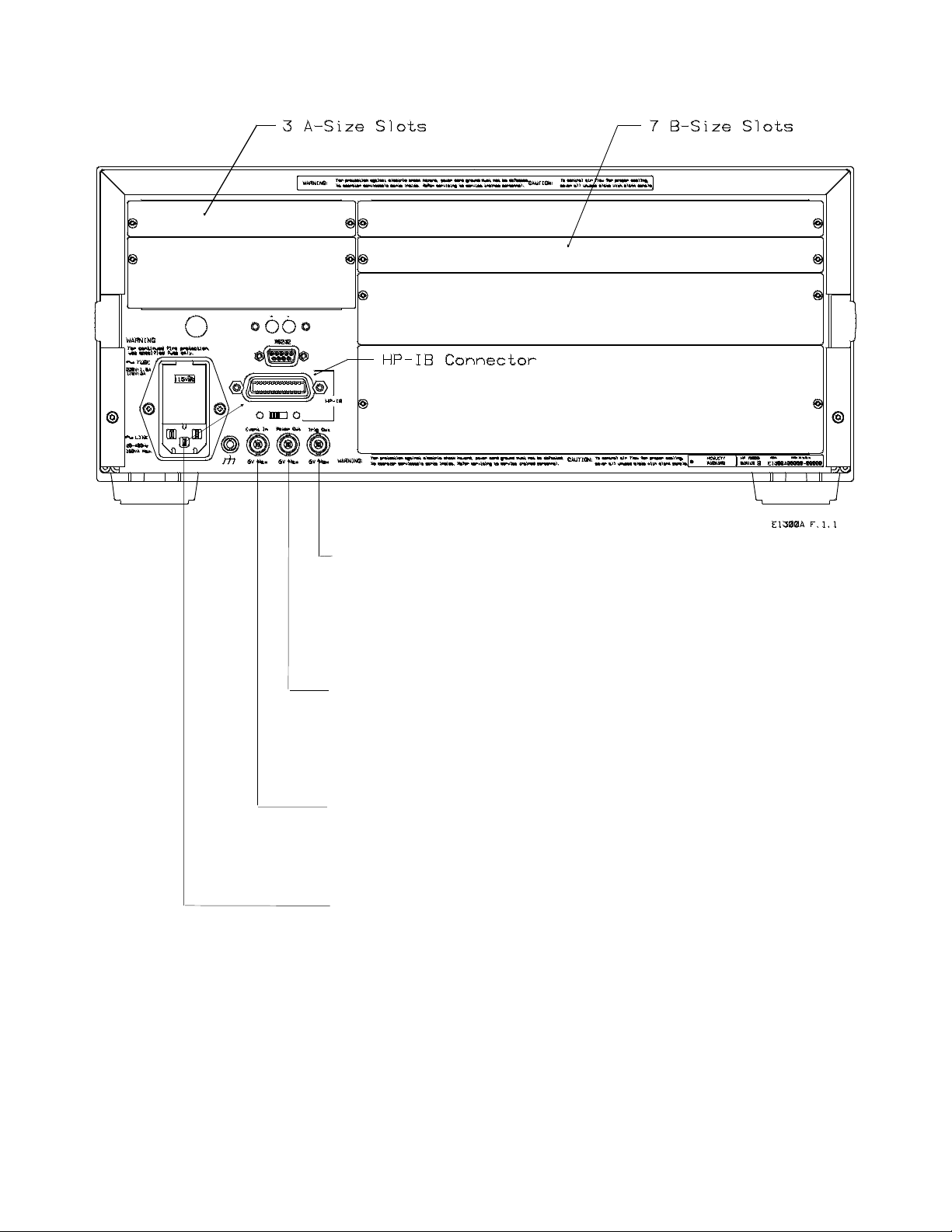
manual for more information). Figure 1-2 shows the E1300B/E1301B
Mainframe’s A- and B-size plug-in module slots, GPIB
and input/o utput ports.
The mainframe comes from the factory with 256 kBytes of non-volatile memory
(RAM) for reading storage. You c an install up to 2 MBytes of opti onal RAM.
The E1320A provides 500 kBytes while the E1321A provides 1 MByte of
memory. Optional RAM replaces the standard memory and is not in addition to
it (e. g. the mainframe with an optional 1 Mbyte module has 1Mbyte availab le).
*
connector, RS-232 port,
* GPIB is the implemen tation of IEEE Std 488.1-1978.
Getting Starte d 1-1
Page 16
Trig Out: Allows an instrument to o utput a negative-going pulse to indicate th e
GPIB
occurrence of som e event such as closing a c hannel on a Switchbox Instrument.
The signal levels are standard TTL (0V to 5V). This pulse can be used to
synchronize external equi pm en t to the instrument (see Ch apter 5 fo r examples).
You direc t th e pulse from the appropriate instrum en t to th e Trig Out port using
the OUTP:STAT ON command.
Pacer Out: Allows you to output a square wave signal to trigger or pace external
equipment such as scanners or voltmeters. Y ou c an c ontrol the period of the
square wave signal and the number of periods output. The si gnal levels are
standard TTL (0V to 5V). Refer to Chapters 4 and 5 for mo re informatio n o n
the Pacer.
Event In: Allows an instrument to be armed or triggered from an external
negative-going signal. The signal levels are stan dard TTL (0V to 5V). Use an
instrument’s ARM:SOUR:EXT command or the TRIG:SOUR:EXT command
to direct the Event In port to that ins trum ent .
RS-232: Serial interface provides a user interface usin g a terminal o r a
computer running terminal em ulator software. The user interface provides the
functionality of the E1301’s keyboard and display. If present, the optional
IBASIC interpreter can be configured to control the RS -232 port.
Figure 1-1. Mainframe Features
1-2 Getting Started
Page 17

1
Instrument
Definition
SC PI-compatible plug-in mo dules installed in th e mainframe are treated as
independent instruments each having a unique secondary GPIB address. As
shown in Figure 1-3, each ins trument is assi gned a dedicated error queue, input
and output buffers, st a tus regist e rs and, if applic a ble, dedicated mainfra me
memory space for reading s or data. An instrument may be composed of a single
plug-in module (such as a counter) or multiple pl ug-in modules (for a Switchbox
or Scanning Voltmeter Instrument). In addition, the mai nframe contains a
built-in instrument called the System Instrument which has a Pacer for timi ng
external devices. The System Instrument also can control the built-in RS-232, as
well as up to seven optional Agilent E1324A plug-in serial interfaces.
Figure 1-2. I nstrument Conc e pt
Getting Starte d 1-3
Page 18

Instrument Logical
Addresses
Instruments are identified by a logical address which directly relates to its GPIB
seco n dary address. Instruments com e from the fac tory with a pres et logical
address. You can chang e the factory setting during installati on (see the "Agi lent
75000 Series B Installation and Getting Started Guide" for instructions).
A single-module instrument must have its logical address set to an integer
multiple of 8 (0, 8, 16, 24, ... 240). In a multiple-module instrument, only one of
the modules has a logical address that is an integer multiple of 8. The other
modules in the multiple-module instrument must have consecutive logical
addresses . For example, in a Scanning Voltmeter, if the vo ltmeter module has a
logical address of 16, the other modules in that instrument must have logical
addresses of 17, 18, 1 9 and so on. The same applies to the System Instrument
who’s logical address fixed at 0. An E1324A plug-in serial interface controlled
by the System Instrument would be set to logical address 1. A second E1324A
would be set to logical address 2 and so on.
Instrument Secondary
Addresses
An instrument’s GPIB secondary address is simply the logical address divided
by 8 (for a multiple-module instrument, the lowest logical address divided by 8).
For example, an instrument with a logical address of 16 h as a secondary address
of 02. Th e secondary address allows acc ess to a particular instrument when
programming vi a GPIB. (The S ystem Instrument’s sec ondary address is 00 and
is the only address that cannot be changed).
Unassigned Modules An unassigned module in an E1300B/E1301B Mainframe is one that does not
have a logical address that is a multiple of 8 (8, 16, 24...240) and is not part of a
Sc anning Voltmeter or Switchbox configuration. You c an only program these
modul es at the register level using the VXI:WRITE and VXI:READ?
commands (see Chapter 5 of this manual for more information on these
commands).
1
Introductory
Programming
Examples
This section shows how to send SCPI and Common Commands to the
mai n frame’s System I nstrument and how to read data back . The fol lowing
assum es that y ou send the commands or read the data over GPIB. To send SCPI
commands or to read data, s pecify the:
• Computer’s GPIB in terface address
• Mainframe’s GPIB prim ary address
• Instrument’s GPIB secondary address
• SCPI comm and string or Common Comm and
1-4 Getting Started
For instruments in the mainframe, the primary address is the same as th e
mai n frame address (i.e., th e factory setting is 09). Th e instrument’s secondary
address is si mply the logical addres s divide d by 8 (e.g., logi cal addresses of 8, 16,
24, or 32, result in secondary addresses of 01, 02, 03, or 04, respectively).
Page 19

Example: Reading the Time This program reads an d prints the time from the System Instrument’s internal
clock. The computer used in the example is an Agilent Series 200/300 computer
with Agilent BAS I C as the program language. The computer in terfaces to the
mai n frame usin g the General Purpos e I n terface Bus (GPIB). Th e GPIB
interface selec t code is 7, the GPIB primary address is 09, and the GPIB
seco n dary address is 00 (System Instrument). Resu lting in a combined address
of 70900.
10 OUTPUT 70900;"*RST" Reset System Instrument using
Common Command
20 OUTPUT 70900;"SY S T :TIME?" Send SCP I query command to
return time
30 ENTER 70900; H,M,S Place hour in H, minutes in M,
se conds in S
40 PRINT H,M,S Print time
50 END
Typical response: + 16, + 15, + 30 (4:15:30 PM)
Example: Setting the Time Set the clock us ing the 24 hour hour,minute,second format. Execute the
following line to set the time to 14,00,00 (i.e., 2:00:00 PM).
SYST:TIME 14,00,00
Example: Reading the Date This program reads an d prin ts the date stored in the mainframe’s i nternal
calendar.
10 OUTPUT 70900;"SY S T:DATE?" Send SCPI query command to
return date
20 ENTER 70900; Y,M,D Place yea r in Y, month in M,
day in D
30 PRINT Y,M,D Print date
40 END
Typical response: + 1989, + 9, + 16 (September 16, 1989)
Example: Setting th e Date Set th e date using the YYYY,MM,DD format. Executing the following line sets
the date to 1990,1,13 (January 13, 1990).
SYST:DATE 1990,1,13
Getting Starte d 1-5
Page 20

1-6 Getting Started
Page 21

Chapter 2
Agilent
Us ing the Front Panel
Usi ng th i s Ch a p ter This chapter shows you how to use the Agilent E1301B Mainframe’s front panel
keyboard and display to operate instruments in th e mainframe. It contains the
following sections:
• Front Panel Features . . . . . . . . . . . . . . . . . . . . . . . . . . . . . . . . . . . 2-1
• Using Menus. . . . . . . . . . . . . . . . . . . . . . . . . . . . . . . . . . . . . . . . . . 2-2
• Executing Commands . . . . . . . . . . . . . . . . . . . . . . . . . . . . . . . . . . 2-9
• Key Descriptions . . . . . . . . . . . . . . . . . . . . . . . . . . . . . . . . . . . . . 2-10
• In Case of Difficulty. . . . . . . . . . . . . . . . . . . . . . . . . . . . . . . . . . . 2-12
• Instrument Menus . . . . . . . . . . . . . . . . . . . . . . . . . . . . . . . . . . . . 2-13
1
Front Panel
Features
2-Line X 40 Character Display Menu Keys
Fig ure 2 -1 shows the f ront panel’s QWERTY keyboard and the dedicated key
groupings. The tutorials in this chapter show how to use most of the dedicated
keys. See “Key Descriptions” near the end of this chapter for a c omplete
des cription of eac h dedicat ed key.
Displa y Control and
Editing Key s
Instrument
Control Keys
QWERTY Keyboard
Figure 2-1. Front Panel Features
Using the Front Panel 2-1
Page 22

1
Using Menus You can access a System Ins trument menu and a variety of other instrument
menus (depending on install ed i nstruments) from the front panel. Thes e m enus
incorporate the most used functi ons but do not provide access to all of the
ins trument comm ands. If a particular functi on is not available from a menu, you
can type the corresponding command string and exec ute it from the f ront panel.
See “ Execu ting Commands” later in this chapter for more inf ormat ion.
When you select an ins trum en t, you are assigning the keyboard and dis play to
that instrument. Thi s means that any menu operation s, comm an ds executed or
recalled, errors displ ayed, etc. pertain only to that instrument. Front panel
operation of an ins trument i s independent from other instruments and
independent from the remote operation of the ins trument. To operate another
ins trument f rom the front panel, you must select that i nstrument.
Note: Typical instruments shown. Actual choices depend on installed instruments
A 60-Second Menu
Tutorial
Figure 2-2. Select an Instrument Menu
Following the power-on sequence or a system reset the display shows the Select
an instr ument menu (see Figure 2-2) whic h lets you select one of the instruments
listed.
The menu keys are located directly below the display. To select a displayed
menu choice, press the function key (f1 - f5) directly below the choice. This
chapter shows key labels in bold text.
• When there are more than five menu c ho ices, an arrow appears on the
right side of the display. Press More to dis pl ay the nex t group of choi ces.
By repeatedly pressing More you can dis play all groups of choic es. Af ter
you have dis pl ayed all groups of choices, pressing More again returns to
the fi rs t group of choi c es.
• When the display is requesting information (input prompt) such as Enter
the device’ s logical address, just type the inf o rmation and press Return.
If you press the wrong menu key and do not want to enter the
requested in format ion, you ca n es cape the input prom pt and stay at
the same menu level by pressing ESC or Prev Menu.
If you make an incorrect entry in response to an input prompt, the
top line of the display will show an error message. When this
happens, jus t select that menu choice agai n (f1 - f5 key s), re-type the
correct information, and pre ss Return.
2-2 Using the Front Panel
Page 23
• Press Prev Menu to return to the previous m enu within an instrum en t
GPIB
GPIB
GPIB
menu or escape from an input prompt. Press Select Instr to return to the
Select an Instrument menu. Note that when you l eave an i nstrument and
return later, you return to the same menu location you were w h en you
left. In addition, any other displayed information (instrument responses
or commands being entered) will also be displayed when you return.
• In additio n to th e menu keys, Clear Instr and Reset I nstr are helpfu l
when operating an inst rum en t. Clear Instr clears the instrument’s front
panel input and output buffers (remote buffers are not cl eared) and
returns to the top l evel o f the instrument menu. Press C lear Instr
whenever an instrument is busy, is not responding to front panel control,
or to abort a command being entered from the front panel. R eset Instr
clears all front panel and rem ote input and o utput buffers and reset s the
instrument.
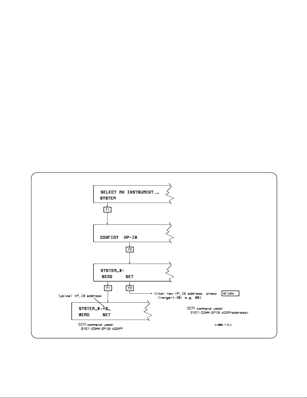
Using the System
Instrument Menu
Ho w to Set or Read the System GPIB Address
The System Instrument menu allows you to:
• Set or read the system GPIB address
• Reset (reboot) the mainframe
• Display the logical addresses of installed instruments
• Display information about installed ins truments
Using the Front Panel 2-3
Page 24

Ho w to Reset the System
GPIB
GPIB
Note: The RESET menu selection is equivalent to the DIAG:BOOT command which has the same eff ect as cycling power to the mainframe.
Pressing Reset Instr from the System Instrument menu is equiva lent to executing the *RST c omm and which resets the S ystem Ins trument.
How to Display Logical Addresse s or Instrument Information
2-4 Using the Front Panel
Page 25

Using the Other
Instrument Menus
Selecting the Switchbox To select the Switchbox, press the function key (f1 - f5) directly below the word
The instrument menus allow you to access the most-used i nstrument functi ons
or to monitor an instrument (monitor mode) while it is being controll ed f rom
remote. We’ll use the Switchbox menu to show you how to use the instrument
menus. Menus are available for many but not all instruments. S ee “Instrument
Menu s”, later in th is chapter, for more information on a particular instrumen t ’s
menu. The Switchbox menu all ows you to:
• Open and Cl ose Channels
• Sc an C h an nels
• Displ a y Module Type and Des cription
• Monitor a Switchbox
• Reset a selected switch module
SWITCH in the “Select an instrument” menu. (If the “Select an instrument”
menu is not being di splayed press Select Instr.)
Note After you press the function key below the word SWITCH, the top line of the
display may show: “Select SWITCH at logical address: _” while the bottom line of
the display lists two or more logical addresses. This means more than one
Switchbox is installed in the mainframe. To select one of the Switchboxes, press
the function key directly below the corresponding logical address.
The charts on the followi ng pages show how to use the Switchbox menu. K eep
the following points in mind when using the menu:
• The card number identif ies a module within the Switchbox. The module
with the lowest logical address is always card number 01. The module
with the next successive l ogical address is card number 02 and so on.
• The @ character is required preceding a channel list when executing a
Switchbox command from the front panel or remote. When entering a
channel lis t in response to a menu prompt however, do not precede it
with th e @ character. Doi n g so causes a syntax error.
Using the Front Panel 2-5
Page 26
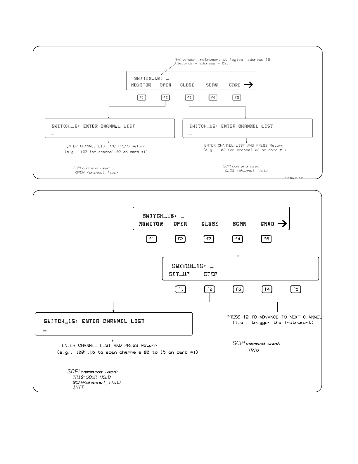
How to Open/Close Channels
How to Scan Channels
2-6 Using the Front Panel
Page 27
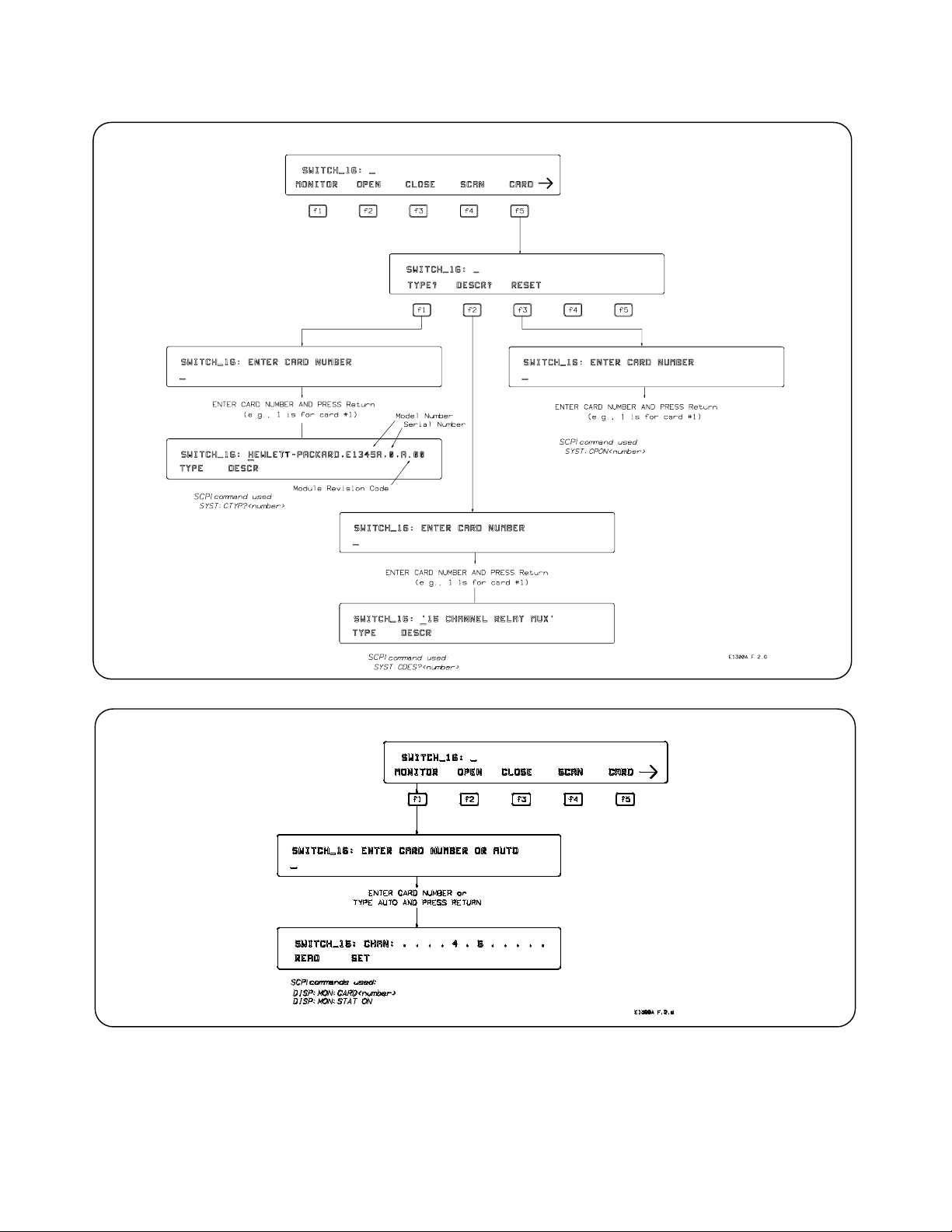
How to Display Monitor Type, Description, or Reset Module
How to Select Monitor Mode
Using the Front Panel 2-7
Page 28
Monitor Mode Monitor mode displays the status of an instrument while it is being controlled
from remote. Moni tor mode is usef ul for debuggi ng programs. You can place an
ins trument i n m onitor mode using front panel menus , or by executing the
DISP:MON:STAT ON command from the front panel or by remote. (Ex ec uting
the remote DISP:MON:STAT ON com mand is the onl y way to assign the
display/keyboard to an instrument from remote.) Pressing most f ront panel keys
will automatically exit monitor mode and return to the instrument menu.
However, you can use the left and right arrow keys in m onitor mode to view long
displays.
Note Enabling monitor mode slows instrument operations. If the timing or speed of
instrument operati o ns is critical (such as making multimeter readings at a
precise tim e interv al), you should not use monitor mode.
Table 2-8 shows the status annunciators that may appear in the bottom l ine of
the display in monitor mode. Some instruments also have device-specific
annunciators (see the plug -in module manual for more informati on).
Table 2-1. Monitor Mode Display Annunciators
A nnunc iator Description
mon Th e instrum e nt is in monitor mode
bsy The instrument is executing a command
err An error has occurred (see “Reading Error
Messages” belo w)
srq A service request has occurred
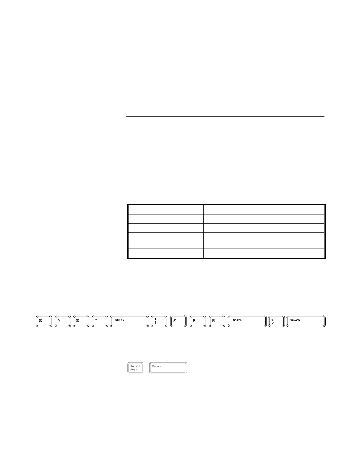
Reading Error Messages Whenever the display is showing the err annunciator, an error has occurred for
the instrument being monitored. You can read the error message, al though
doing so cancels moni to r m o de. To read an error message, press the follo wing
keys:
The error message will be displayed in the top line of the display. To see if
another error was logged, repeat the above keystrokes or press:
After you have read all the error messages, executing the SYST:ERR?
command causes the display to show : + 0 No error. After reading th e error
message(s), press f1 to return to moni to r m ode.
2-8 Using the Front Panel
Page 29

1
Executing
Commands
Fr om the front panel, you can type and execute IEEE 488.2 Common
Comman ds and SC PI C ommands for the instrument presently selected by the
Select an instrument menu. (How ever, you cannot execute a command when the
display is requesting that you input information.) This is particularly useful for
access ing functions not availabl e in an instrument’s menu. For exam pl e, the
System Instrument contai ns a Pacer that can be programmed to output a square
wave signal on the mainframe’s Pacer Out port. From the System Instrument
menu, you can program the Pacer to output 10 s quare w ave cycles with a period
of 1 second each by typing the following commands and pressi ng Return after
each command (see Chapter 3 f o r mo re informati on o n th e Pac er).
SOUR:PULS:COUN 10
SOUR:PULS:PER 1
INIT:IMM
TRIG:SOUR IMM
As another exampl e, after sel ec ting the Switchbox, suppose you must s et up and
execute a scan list with autom atic advan ce (automati c advance is n o t available
from the menu). You can do this by typing the f ollowing command string and
pressing Return (notice that by linking the commands to gether with a sem icolon
and colon you need press Return only once).
TR IG:SOUR IMM;:SCAN (@100:105);:INIT
Editing The display editing keys (shown on the following page) allow you to edit
user-en tered data or commands. When editing, the display is in insert mode.
That is, typed characters will be inserted into the string at the present cursor
position.
Using the Front Panel 2-9
Page 30

1
Key Descriptions Thi s section explains the function of each of the front panel’s dedicated keys. If
a key is not func tional in a particular si tuation, pressing that key does nothing
except to cause a beep. Users of the optional IBASIC interpreter shoul d refer to
their IBASIC manual set for additi onal editing functions.
Menu Ke ys
Selects the menu choice displayed directly above each key.
Returns to the Select an instr ument menu.
Returns to the previ ous menu lev el within an instrument menu or escapes from
an input prompt. When y ou reach the top of an i nstrument’s menu, pressi ng
Prev Menu does no th ing except to cause a beep.
The display can sho w a maximum o f five menu c h o ices at a time. W h en th ere are
more than five menu c h oices, an arrow appears on the right side of th e display.
Press More to display the next group of choi ces. By repeatedly pressing More
you can dis pl ay all groups of c hoices. After you have displayed all groups of
choices, pressing More again returns to the first group of c hoices.
Disp lay Control &
Editing Keys
Recalls the last command entered from the front panel. After recalling a
command, it can be edited or re-executed. You can recall from a stack of
prev iously executed comman ds by repeatedly pressing R ecall Prev. When you
reach the bottom o f the stack (the last line in th e bu ffer), press ing Recall Prev
does nothing except to cause a beep. Press ing Shift with Recall Prev recalls the
last SCPI command gen erated by a menu operation . For example, readi n g the
tim e u sing the menus (SYSTEM, TIME, READ) generates and executes the
SCPI com m and SYST:TIME?. A recalled command can be executed by
pressing the Return key. You can also edi t a recalled command before you
execute it.
Accesses commands in the opposite order to that of Recall Prev. Pressing Recall
Next does nothi ng until you have pressed Recall Prev at least twi ce.
Performs the same function as Prev Menu.
(Right arrow key.) Moves the c u rsor one character s pac e to th e right while
leaving characters i ntact. Use the ri ght arrow k ey to scroll displays that are
longer than the display size. Pres sing Sh i ft followed by the righ t arrow key
moves the cursor to the end of th e line. Pressing CTRL followed by the right
arrow key m oves the cursor 4 character s pac es to the right.
2-10 Using the Front Panel
(Left arrow key.) Moves the cursor one character space to the l eft while leaving
characters intact. Use the l eft and right arrow keys to scroll displays that are
longer than the display size. Pres sing Shift f ollowed by the left arrow key moves
Page 31

the cursor to the beginni ng of the li ne. Pressing CTRL followed by the left
arrow key m oves the cursor 4 character spaces to the left.
Erases the character at the presen t cursor position (fo r user-entered data only).
Erases the character to the left of the curso r (for user-en tered data onl y).
(Clear-to-end key .) Erases al l characters f rom the present cursor posi tion to the
end of the input line (for user-entered data only). Press ing Shift followed by the
cl ear- to -end key erases the en tire line and moves the cursor to the beginni n g of
the line.
Selects the upper-case alphabetic characters or the ch arac ter shown on the top
half of a key. You can either hold down Shift while pressing another key or press
and release Shift and then press another key.
Sets all alphabeti c keys to uppercase (capitals); does not aff ect the other keys.
To ret urn to lowercas e , press Caps Lock again.
Instrume nt C o ntro l
Keys
Other Keys
Resets only the selected instrument (equi valen t of ex ecutin g *RST). Rese t Instr
also clears the instrument’s front panel and remote input and output buffers.
R eset Instr is the only front panel key that can affect an ins trument being
operated from remote.
Clears the front panel input and output buffers (remote buffers are not cleared)
of th e selected instrument and returns to the to p level of the instrument m en u.
Press Clear Instr whenever an instrument is busy, is not responding to front
panel control, or to abort a command being entered from the front panel.
End of line. Enters your responses to menu prompts. Exec utes commands
entered from the front panel keyboard.
Selects al ternate key definitions. You can either hold down CT RL while pressing
another key or press and release CTRL and then press another k ey. Th ese
CTRL key sequences provide sho rt- cuts for some menu key sequences as well as
additional functions not directly av ailable from dedicated front panel keys. For
a complete lis t o f all CTRL key sequenc es see table 3-3 i n th e n ext chapter.
Using the Front Panel 2-11
Page 32

1
In Case of Diffi culty
Problem: Problem Cause/ Solu t io n :
Error -113 undefined header error occurs after entering
data in response to a menu prompt.
Following the power-on sequence or sy stem reset the
display shows:
Configuration errors. Select SYSTEM
Press a ny key to continue_
The display shows: "instrument in local lockout" .
Menus seem to work but nothing happens w hen I reach
the bottom level or try to execute a com mand.
Display cannot be removed from m onitor mode. Monitor mode was entered from remote
Display shows:
Can not connect to ins trument
Press a ny key to continue_
For some commands used by the menus, the data
entered is appended to a com mand header. For
example, if you enter "1" as the port number for a digital
I/O module, the command used is
DIG:HAND1:MODE NONE where HAND1 indicates
the port number. If your entry was invalid or incorrect,
error -113 occurs.
An unnassigned device (incorrect logical address) w as
detected, or the contents of non-volatile memory may
have been lost, If you cycle power or perform system
reset, the display will show the logical address of the
unassigned device. You can al so check the logical
addresses u sing the C ONFIG? -- LADDS branch of th e
System Instrument menu. Refer to Chapter 1 of thi s
manual for a discus sion of logical addresses and
unassigned devices.
The front panel has been locked-out (GPIB local
lockout). You can re-enable menu operation by
cancelling local lockout (from remote) or by cycling
mai n frame power.
(DISP:MON:STAT ON command) and the front panel
has also been lock ed out (GPIB local lockout). Either
cancel the l ocal l oc kout or ex ecute
DISP:MON:STAT OFF (from remote).
A hardware or software problem has oc c ured in the
ins trument prev enting it from responding to front panel
control.
After selecting an instrument the display shows:
busy.
Display shows:
Ins trument in use by another display.
Press a ny key to continue_
2-12 Using the Front Panel
The instrument is busy performing an operation. Press
Clear Instr to abort the instrument operations and
allow the front panel to access the instrument.
The instrument has al ready been selected f rom th e
Display Terminal Interface. An instrument can only be
“attached” to o ne display at a time. At the terminal,
return to the “Select instrument” menu. Th e instrument
can now be selec ted from the Front Panel.
Page 33

2
Instrument Menus This sec tion contains charts showing the s tructure and content for all front panel
ins trument menus . Als o shown in the charts are the SCPI or Common
Commands used and descriptions of menu-controlled instrument operations.
This section c ontains the f ollowing charts:
• S ystem Instrument Menu. . . . . . . . . . . . . . . . . . . . . . . . . . . . . . . 2-14
• Swi tc hbox Menu . . . . . . . . . . . . . . . . . . . . . . . . . . . . . . . . . . . . . . 2-16
• S canning Voltmeter Menu . . . . . . . . . . . . . . . . . . . . . . . . . . . . . 2-18
• Agilent E1326A 5 1/2 Digit Multimeter Menu . . . . . . . . . . . . . 2-20
• Agilent E1328A 4-Channel D/A Converter Menu. . . . . . . . . . 2-21
• Agilent E1330A Quad 8-Bit Digital I/O Menu. . . . . . . . . . . . . 2-22
• Agilent E1332A 4-Channel Counter/Totalizer Menu . . . . . . . 2-24
• Agilent E1333A 3-Channel Universal Counter Menu. . . . . . . 2-26
Using the Front Panel 2-13
Page 34

instruments
2-14 Using the Display Terminal Interface
the specified logical address. (Refer to the
Command R eference for details)
DEVICE logical address VXI:CONF:DLIS? < log_addr> Displays information about the device at
Level 1 Level 2 Level 3 Level 4 Level 5 Level 6 User Entry Command(s ) Used Description
System Instrument Menu
Menu Levels and Content
SYSTEM CON FIG? L ADDS VXI:CONF:DLAD ? Displays lo gical addresses o f mainframe
1200 card number SYST:COMM:SER[n]:BAU D 1200 Sets the serial interface baud rate to 1200
2400 card number SYST:COMM:SER[n]:BAU D 2400 Sets the serial interface baud rate to 2400
9600 card number SYST:COMM:SER[n]:BAU D 9600 Sets the serial interface baud rate to 9600
19200 card number SYST:COMM:SER[n]:BAU D 19200 Sets the serial interface baud rate to 19200
SET 300 card number SYST:COMM:SER[n]:BAU D 300 Sets the serial interface baud rate to 300
SET GPIB address SYST:COMM:GPIB:ADDR < addre ss>
GP IB READ SYST:COMM:GPIB:ADD R? Displays GPIB address
RS232 BAUD READ card number SYST:COMM:SER[n]:BAU D? Read current baud rate
PARITY READ card number SYST:COMM:SER[n] :PAR? Read current parity type
OD D card n umber SYST:COMM:SER[n]:PAR ODD Sets the serial interface parity to odd
ONE card number SYST:COMM:SER[n]:PA R ONE Sets the serial interface parity to one
ZERO card number SYST:COM M:SER[n]:PAR ZERO Sets the serial interface parity to zero
NONE card n umber SYST:COMM:SER[n]:PAR NONE Sets the serial interface parity to none
SET EVEN card n umber SYST:COMM:SER[n]:PAR EVEN Sets the serial interface parity to even
BITS READ card number SYST:COMM:SER [n]:BITS? Read current data bit width
8 card n umber SYST:COMM:SER[n]:BITS 8 Sets the data width to 8 bits
SET 7 card number SYST:COMM:SER [n]:BITS 7 Sets the data width to 7 bits
PACE READ card numbe r SY ST:COMM:SER[n]:PAC E? Read current pacing typ e
NONE card number SYST:COMM:SER[n]:PACE NONE Disables XON/ XOFF software handshaking
SET X ON/ OFF card number SYST:COMM:SER[n]:PACE XON Enables XON/XOFF software handshaking
(continued on following page)
Page 35

se ttings into non-volatile storage.
Using the Display Terminal Interface 2-15
VXI:WRIT <laddr>,<reg>,<data> Write data to register in A16 address space.
reg_num, data
OFF card number SYST:COMM:SER[n] :CONT:DTR OFF Set DTR line to static -V
IBFULL ca rd number SYST:COMM:SER[n]:CONT :DTR IBF Set DTR for hardware handshaking
STANDRD card number SYS T:COMM:S ER[n] :CONT :DTR STAN DTR operates to RS-232 standard
OFF card number SYST:COMM:SE R[n]:CONT:RTS OF F Se t RTS line to static -V
IBFULL ca rd number SYST:COMM:SER[n]:CONT :RTS IBF Set RTS for hardware handshaking
STANDRD card number SYST:COMM:SER[ n] : CONT:RTS STAN RTS operat es to RS-232 standar d
stored in non-volatile memo ry
SET ON card number SYST:COMM:SER[n]:CONT:DTR ON Set DTR line to static + V
CONTROL DTR READ card number SYST:COMM:SER[n] :CONT:DTR? Read current setting for DTR line
(continued from previous page)
System Instrument Menu
Level 1 Level 2 Level 3 Level 4 Level 5 Level 6 User Entry Command(s) Used Description
Menu Levels and Content
SET ON card number SYST: COM M: SER[ n]:CONT: RTS ON Set RTS li ne t o static + V
RTS READ card number SYST:COMM: S E R[n]:CONT:RTS? Read cur rent setti ng for RTS line
STORE card number DIAG:C OMM:SER[n]:STORE Store current serial communications
WRITE laddr,
DEBUG READ laddr, reg_num VXI:READ? < laddr> ,< reg> Read register in A16 address space.
SET time SYST:TIME < time> Set the system clock
TIME RE AD SYST:TIME? Read the current system clock
SET date SYST:DATE < date> Set the system calendar
DATE READ SYST:DATE? Read the current system calendar
RES ET DIAG:BOOT Resets mainframe using the configuration
Page 36

othe r number= fail)
2-16 Using the Display Terminal Interface
OPEN channel list † OPEN (@channel_list) Open channel(s)
CLOSE channel list † CLOS (@channel_list) Close channel(s)
SCAN SET_UP channel list † TRIG:SOUR HOLD;:SCAN <channel_list> ;:INIT Set up channels to scan
Level 1 Level 2 Level 3 User Entry Command( s ) Used Description
Switchbox Menu
Menu Levels and Content
SWITCH MONITOR card number ‡ or AUTO DISP:MON:CARD <card_number> ;STAT ON Monitor instrument operations
STEP channel list † TRIG Step to next channel in scan list
DESCR? card number ‡ SYST:CDES? < card_number> Display module description
RESET card number ‡ SYST:CPON < ca rd_number> Re turn module to power-on state
CARD TYPE? card number ‡ SYST:CTYP? < card_number> Display module ID information
TEST * TST? Runs self-test, displays result s (+ 0= pass; any
† Channel lists are of the form “ccnn” (single channel), “ccnn,cc nn” (two or more channels) or “ccnn:ccnn” (range of channels); where “cc” is the card number and “nn” is the channel
number. For example, to access channel 2 on card number 1 spec ify 102.
‡ The card number identifies a module within the Switchbox. The switch modu le with the lowest log i cal address is a lways ca rd number 01. The switch module with the next
succes sive logical address is ca rd number 02 and so on.
Page 37

Notes
Using the Front Panel 2-17
Page 38

DISP:MON:CHAN <channel_list>;STAT O N Monitor instrument ope rations
2-18 Using the Display Terminal Interface
for auto
E channel list † ME AS:TEMP? TC,E, < channel_lis t> Measure °C of E thermocouple on each channel
J channel list † MEAS:TEMP? TC,J, <channel_list> Measure °C of J thermoc ouple on each channel
K channel list † ME AS:TEMP? TC,K, < channel_list> Measure °C of K thermocouple on each channel
N14 channel list † MEAS:TEMP? TC,N14, <channel_list> Measure °C of N14 thermocouple on each channel
N28 channel list † MEAS:TEMP? TC,N28, <channel_list> Measure °C of N28 thermocouple on each channel
R cha nnel list † MEAS:TEMP? TC,R, < channel_list> Measure °C of R thermocouple on each channel
S channel list † ME AS:TEMP? TC,S, < channel_list> Measure °C of S thermocouple on each channel
T channel list † MEAS:TEMP ? TC,T, <channel_list> Measure °C of T thermocouple on e ach channel
5K channel list † MEAS:TEMP? THER,5000,< channel_list> Measure °C of 5k Ω thermistor on each channel
10K channel list † MEAS:TEMP? THER,10000,< channel_list> Measure °C of 10k Ω thermistor on each channel
392 cha nnel list † MEAS:TEMP? RTD,92,< channel_list> Measure °C of 392 RTD on each channel (4-wire)
POISSON chan nel list † MEAS:STR:HPO? < channel_list> Measure strain with Poisson half bridge
BENPOIS channel list † MEAS:STR:FBP? < channel_list>, Measure strain with Be nding Poiss on full bridge
POISSON chan nel list † MEAS:STR:FPO? < channel_list> Measure strain with Poisson full bridge
VDC channel list † MEAS:VOLT:DC? < channel_list> Measure DC voltage on each channel
VAC channel list † MEAS:VOLT:AC? <channel_list> Me asure AC voltage on each channel
Level 1 Level 2 Level 3 Level 4 User Entry Command( s ) Used Description
Scanning Voltmeter Menu
Menu Levels and Content
VOLTMTR MONITOR channel list † or 0
THERMIS 2252 channel list † MEAS:TEMP? THER,2252,< channel_list> Measure °C of 2252 Ω thermistor on each channel
OHM channel list † MEAS:RES? < channel_list> Measure 2-wire resistance on e ach channel
TEMP TCOUPL E B channel list † MEAS:TEMP? TC,B, <channel_list> Measure °C of B thermocouple on each channel
RTD 385 channel list † MEAS:TEMP? RTD,85,<channel_list> Measure °C of 385 R TD on each channel (4-wire)
HALF B ENDING c hannel list † MEAS:STR:HBE N? <channel_list> Measure strain with bending half bridge
STRAIN QUA RTER channel list † MEAS:STR:Q UAR? < channel_ list> Measure stra in with quarter bridge
FULL BENDING channel list † MEAS:STR:FBEN? < channel_list> Measure strain with bending full bridge
(continued on following page)
Page 39

number= f ail)
Using the Display Terminal Interface 2-19
UNSTRN channel list † MEAS:STR:UN ST? < channel_list> Measure bridge unstrained
DIAG COMPRES channel list † MEAS:STR:Q COM? < channel_list> Compression shunt diag nostic
Level 1 Level 2 Level 3 Level 4 User Entry Command( s ) Used Description
Scanning Voltmeter Menu
Menu Levels and Content
(continued from previous page)
TENSION channel list † MEAS:STR:QTEN? < c hannel_list> T ension shunt diagnostic
DESCR? card number ‡ SYST:CDES? < card_number> Displays module description
CARD TYPE? card num be r ‡ SYST:CTYP? < card_number> Displays module ID information
TEST * TST? Runs self-test, displays results ( + 0= pass; any ot her
† Channel lists are of the form “ccnn” (single channel), “ccnn,cc nn” (two or more channels) or “ccnn:ccnn” (range of channels); where “cc” is the card number and “nn” is the channel
number. For example, to access channel 2 on card number 1 spec ify 102.
‡ The card number identifies a module within the Switchbox. The switch modu le with the lowest log i cal address is a lways ca rd number 01. The switch module with the next
succes sive logical address is ca rd number 02 and so on.
Page 40

VDC MEAS:VOLT:DC? Measure DC volts
2-20 Using the Display Terminal Interface
VAC MEAS:VOLT:AC? Measur e AC volts
OHM MEAS:FRES? Measure 4-wire ohms
Level 1 Level 2 Level 3 Level 4 User Entry Command(s ) Used Description
Agilent E1326B/E1411B 5 1/2 Digit Multimeter (Standalone) Menu
Menu Levels and Content
VOLTMTR MONITOR DISP:MON:STAT ON Display instrument operations
5K MEAS:TEMP? FTH,5000 Measure °C of 5kΩ thermistor (4-w ire measur ement)
10K MEAS:TEMP? FTH,10000 Measure °C of 10kΩ thermistor (4-wire measurement)
392 MEAS:TEMP FRTD,92? Measure °C of 100Ω RTD with alpha = 392 (4-wire measurement)
RTD 385 MEAS:TEMP FRTD,85? Measure °C of 100Ω RTD with alpha = 385 (4-wire measurement)
TEMP THERMIS 2252 MEAS:TEMP? FTH,2252 Measure °C of 2252Ω thermistor (4-wire measurement)
TEST *TST? Run sel f-test, di spl ay results (0= pass; any other number = fai l)
† Channel lists are of the form “ccnn” (single channel), “ccnn,cc nn” (two or more channels) or “ccnn:ccnn” (range of channels); where “cc” is the card number and “nn” is the channel
number. For example, to access channel 2 on card number 1 spec ify 102.
‡ The card number identifies a module within the Switchbox. The switch modu le with the lowest log i cal address is a lways ca rd number 01. The switch module with the next
succes sive logical address is ca rd number 02 and so on.
Page 41

number= f ail)
Using the Display Terminal Interface 2-21
CHAN2 DISP:MON:CHAN 2;STAT ON Monitor instrument ope rations on c hannel 2
CHAN3 DISP:MON:CHAN 3;STAT ON Monitor instrument ope rations on c hannel 3
CHAN4 DISP:MON:CHAN 4;STAT ON Monitor instrument ope rations on c hannel 4
AUTO DISP:MON:CHAN AUTO;STAT ON Monitor instrument operations on active channel
Level 1 Level 2 Level 3 Level 4 User Entry Command(s) Used Description
Agilent E1328A 4-Channel D/A Converter Menu
Menu Levels and Content
D/A MONITOR CHAN1 DISP:MON:CHAN 1;STAT ON Monitor instrument ope rations on c hannel 1
CHAN2 voltage † VOL T2 < voltage> Output voltage on channel 2
CHAN3 voltage † VOL T3 < voltage> Output voltage on channel 3
CHAN4 voltage † VOL T4 < voltage> Output voltage on channel 4
OUTPUT VOLTAGE CHAN1 voltage † VOLT1 < voltage> Output voltage on channel 1
CHAN2 current ‡ CURR2 < current> Output current on channel 2
CHAN3 current ‡ CURR3 < current> Output current on channel 3
CHAN4 current ‡ CURR4 < current> Output current on channel 4
CURRENT CHAN1 current ‡ CURR1 < current> Output current on channel 1
TEST *TST? Run self-test, display result s (+ 0= pass; any other
†Enter voltage values in volts. Typical examples are: + 3.5, -2, + 500E-3.
‡Enter current values in amps. Typical examples are: .05, + 200E-3.
Page 42

active port
2-22 Using the Display Terminal Interface
PORT1 DISP:MON:CHAN 1;STAT ON Monitor instrument operations on port 1
PORT2 DISP:MON:CHAN 2;STAT ON Monitor instrument operations on port 2
PORT3 DISP:MON:CHAN 3;STAT ON Monitor instrument operations on port 3
Level 1 Level 2 Level 3 Level 4 User Entry C ommand( s) Used Description
Agilent E1330A Quad 8-Bit Digital Input/Output Menu
Menu Levels and Content
DIG_I/ O MONITOR PO RT0 DISP:MON:CHAN 0;STAT ON Monitor instrument operations on port 0
PORT1 DIG :HA ND1:MODE NONE;:M EAS:DIG:DATA1? Reads port 1 after handshake
PORT2 DIG :HA ND2:MODE NONE;:M EAS:DIG:DATA2? Reads port 2 after handshake
PORT3 DIG :HA ND3:MODE NONE;:M EAS:DIG:DATA3? Reads port 3 after handshake
PORT1 bit (0-7) DIG:HAND1:MODE NONE;:MEAS:DIG:DATA1:BITm? Rea ds bit m on port 1 after handshake
PORT2 bit (0-7) DIG:HAND2:MODE NONE;:MEAS:DIG:DATA2:BITm? Rea ds bit m on port 2 after handshake
PORT3 bit (0-7) DIG:HAND3:MODE NONE;:MEAS:DIG:DATA3:BITm? Rea ds bit m on port 3 after handshake
AUTO DISP:MON:CHAN AUTO;STAT ON Monitor instrum ent opera tions on any
READ R_BYTE PORT0 DIG:HAND0:MODE NONE;:MEAS:DIG:DATA0? Reads p ort 0 after handshake
R_BIT PORT0 bit (0-7) DIG:HAND0:MODE NONE ;:MEAS:DIG:DAT A0:BITm? Reads bit m on port 0 after handshake
WRITE W_BYTE PORT0 data (0-255) DIG:HAND0:MODE NONE;:DIG:DATA0 <data> Writes data to port 0
PORT1 data (0-255) DIG:HAND1:MODE NONE;:DIG:DAT A1 < data> Writes data to port 1
PORT2 data (0-255) DIG:HAND2:MODE NONE;:DIG:DAT A2 < data> Writes data to port 2
PORT3 data (0-255) DIG:HAND3:MODE NONE;:DIG:DAT A3 < data> Writes data to port 3
W_BIT PORT0 bit (0- 7), value (0,1) DIG:HA ND0:M ODE NONE;:DIG:DATA0:BITm <value> Writes data to bit m o n port 0
PORT1 bit (0-7), value (0,1) DIG:HAND1:MODE NONE;:DIG:DATA1:BITm <value> Writes data to bit m on port 1
PORT2 bit (0-7), value (0,1) DIG:HAND2:MODE NONE;:DIG:DATA2:BITm <value> Writes data to bit m on port 2
PORT3 bit (0-7), value (0,1) DIG:HAND3:MODE NONE;:DIG:DATA3:BITm <value> Writes data to bit m on port 3
Page 43

Notes
Using the Front Panel 2-23
Page 44

NEG SENS1:EVEN:SLOP NEG Negative level trigger slope for channe l 1
2-24 Using the Display Terminal Interface
NEG SENS2:EVEN:SLOP NEG Negative level trigger slope for channe l 2
NEG SENS3:EVEN:SLOP NEG Negative level trigger slope for channe l 3
NEG SENS4:EVEN:SLOP NEG Negative level trigger slope for channe l 4
CHAN2 DISP:MON:CHAN 2;STAT ON Monitor instrument operations on channel 2
CHAN3 DISP:MON:CHAN 3;STAT ON Monitor instrument operations on channel 3
CHAN4 DISP:MON:CHAN 4;STAT ON Monitor instrument operations on channel 4
Level 1 Level 2 Level 3 Level 4 Level 5 User Entry Command(s) Used Description
Agilent E1332A 4-Channel Counter/Totalizer Menu
Menu Levels and Content
COUNTER MONITOR CHAN1 DISP:MON:CHAN 1;STAT ON Monitor instrument operations on channel 1
CHAN3&4 voltage † SENS3 :EVEN:LEV <valu e> Set level trigger vo ltage for channels 3 & 4
AUTO DISP:MON:CHAN AUTO;STAT ON Monitor instrument ope rations on active channel
INPUT LEVEL CHAN1&2 voltage † SENS1:EV EN:LEV <value> Set level trigger voltage for channels 1 & 2
CHAN2 POS SENS2:EVEN:SLOP POS Positi ve level tr igger slope for channel 2
SLOPE CHAN1 POS SENS1: EVEN: SLOP POS Posit ive level trigger slope for channel 1
CHAN3 POS SENS3:EVEN:SLOP POS Positi ve level tr igger slope for channel 3
CHAN4 POS SENS4:EVEN:SLOP POS Positi ve level tr igger slope for channel 4
OFF INP:ISOL OFF Inpu t isolation off
ISO LATE ON INP:ISOL ON Input isolation on
OFF INP:FILT OFF Input filter off
FREQ frequenc y ‡ INP:FILT:FREQ < value> Set input filter frequency
FILTER ON INP:FILT ON Input filter on
CHAN3 TRIG:SOUR IMM;:MEAS3:FREQ? Frequency measurement on channel 3
F REQ CHAN1 TRIG :SOUR IMM;:MEAS1:F REQ? Frequency measurement on channel 1
CHAN3 TRIG:SOUR IMM;:MEAS3:PER? Period measurement on channel 3
PERIOD CHAN1 TRIG:SOUR IMM;:MEAS1:PE R? Period measurement on channel 1
(continued on following page)
Page 45

count
Using the Display Terminal Interface 2-25
count
number= f ail)
CHAN3 TRIG:SOUR IMM;:MEAS3:TINT? T i me interval measurement on cha nnel 3
TIMEINT CHAN1 TRIG:SOUR IMM;:MEAS1:TINT? Time interva l measurement on channel 1
POS_PW CHAN2 TRIG:SO UR IMM ;:MEAS2:PWID? Positive pulse width measurement on channel 2
Level 1 Level 2 Level 3 Level 4 Level 5 User Entry Command(s) Used Description
Agilent E1332A 4-Channel Counter/Totalizer Menu
Menu Levels and Content
(continued from previous page)
CHAN4 TRIG:SOUR IMM;:MEAS4:PWID ? Positive pu lse width measurement on channel 4
READ F ETC1? Get up/ down count from channels 1 & 2
CHAN4 TRIG:SOUR IMM;:MEAS4:NWID? Negative pulse width measurement on channel 4
NEG_PW CHAN2 TRIG :SOUR IMM;:MEAS2:NWID? Negative pulse width mea surement o n channel 2
UDCOUNT CHAN1 START TRIG:SOUR IMM;:CONF1:U DC;:INIT1 Up/ down count, subtract ch. 2 count from ch. 1
READ F ETC3? Get up/ down count from channels 3 & 4
READ FETC1? Get totalize co unt on channel 1
CHAN3 START TRIG:SOUR IM M;:CONF3:UDC;:INIT3 Up/down count, subtract ch. 4 count from ch. 3
TOTALIZ CHAN1 START TRIG:SOUR IMM;:CONF1:TOT;:INIT1 Totalize on channel 1
CHAN2 START TRIG:SOUR IMM;:CONF2:TOT;:INIT2 Totalize on channel 2
READ FETC2? Get totalize co unt on channel 2
READ FETC3? Get totalize co unt on channel 3
CHAN3 START TRIG:SOUR IMM;:CONF3:TOT;:INIT3 Totalize on channel 3
READ FETC4? Get totalize co unt on channel 4
CHAN4 START TRIG:SOUR IMM;:CONF4:TOT;:INIT4 Totalize on channel 4
TE ST * TST? Run self-test, display results ( + 0= pass; any ot her
†Enter voltage values in volts. Typical examples are: + 3.5, -2, + 500E-3.
‡Enter frequency value in hertz. Typical examples are: 60, 120, 1E3.
Page 46

NEG SENS1:EVEN:SLOP NEG Negative trigger slope for channel 1
2-26 Using the Display Terminal Interface
NEG SENS2:EVEN:SLOP NEG Negative trigger slope for channel 2
CHAN2 DISP:MON:CHAN 2;STAT ON Monitor instrument operations on channel 2
CHAN3 DISP:MON:CHAN 3;STAT ON Monitor instrument operation on channel 3
Counter Menu
Level 1 Level 2 Level 3 Level 4 Level 5 User Entry Command(s) Used Description
Menu Levels and Content
COUNTE R MONITOR CHAN1 DISP:MON:CHAN 1;STAT ON Monitor instrument operations on channel 1
Agilent E1333A 3-Channel Universal
CHAN2 voltage † SENS2:EVEN:LEV< value> Set trigger level voltage for channel 2
AUTO DISP:MON :CHAN AUTO;STAT ON Monitor instrument operatio ns on active channel
INPUT LEVEL CHAN1 voltage † SENS1:EVEN:LEV< value> Set trigger level voltage for channel 1
CHAN2 POS SENS2:EVEN:SLOP POS Positive tri gger slope f or channel 2
SLOPE CHAN1 POS SENS1:EVEN:SLOP POS Posit ive trigger slope for channel 1
DC INP :CO UP DC DC-coupled input (channels 1&2)
COUPLE AC INP:COUP AC AC-c oupled input (channels 1 & 2 only)
1_MOHM INP:IMP 1e6 1MΩ input resistance (channels 1 & 2 only)
20dB INP:ATT 20 20dB input attenuation (channels 1 & 2 only)
IMPED 50_OHM INP:IMP 50 50Ω input resistance (channels 1 & 2 only)
ATTEN 0dB INP:ATT 0 No input attenuation (channels 1 & 2 only)
OFF INP:FILT OFF Input filter off (channels 1 & 2 on ly)
FILTER ON INP:F ILT ON Input filter on (channels 1 & 2 only)
CHAN2 TRIG:SOUR IMM;:MEAS2:FREQ? Frequency measureme nt on channel 2
CHAN3 TRIG:SOUR IMM;:MEAS3:FREQ? Frequency measureme nt on channel 3
F REQ CHAN1 TRIG:SOUR IMM;:MEAS1:FREQ? Frequency measurement on cha nnel 1
CHAN2 TRIG:SOUR IMM;:MEAS2:PER? Period measurement on channel 2
PERIOD CHAN1 TRIG:SOUR IMM;:MEAS1:PE R? Period mea surement on channel 1
(continued on following page)
Page 47

number= f ail)
Using the Display Terminal Interface 2-27
CHAN2 TRIG:SOUR IMM;:MEAS2:TINT? T i me interval measurement on cha nnel 2
Agilent E1333A 3-Channel Universal
Counter Menu
TIMEINT CHAN1 TRIG:SOUR IMM;:MEAS1:TINT? Time interval measurement on channel 1
Level 1 Level 2 Level 3 Level 4 Level 5 User Entry Command(s) Used Description
Menu Levels and Content
(continued from previous page)
POS_PW CHAN1 TRIG:SO UR IMM ;:MEAS1:PWID? Positive pulse width measurement on channel 1
READ FETC1? Display totaliz e count
CHAN2 TRIG:SOUR IMM;:MEAS2:PWID ? Positive pulse width measurement on channel 2
CHAN2 TRIG:SOUR IMM;:MEAS2:NWID? Negative pulse width measurement o n channel 2
CHAN2 TRIG:SOUR IMM;:MEAS2:RAT? Ratio of channel 2/channel 1
NEG_PW CHAN1 TRIG:SOUR IMM;:MEAS1:NWID? Nega tive pulse width measurement on channel 1
RATIO CHAN1 TRIG:SOUR IMM;:MEAS1 :RAT? Ratio of channel 1/channel 2
TOTALIZ CHAN1 START TRIG:SOUR IMM;:CONF1:TOT;:INIT1 Totalize on channel 1
READ FETC2? Display totaliz e count
CHAN2 START TRIG:SOUR IMM;:CONF2:T OT;:INIT2 Totalize on channel 2
TEST * TST? Run self-t est, di splay results (+ 0= pass; any other
†Enter voltage values in volts. Typical examples are: + 3.5, -2, + 500E-3.
Page 48

Notes
2-28 Using the Front Panel
Page 49

Chapter 3
Us ing the Dis play Terminal Interface
Using this Chapter This chapter shows you how to use the Agilent E1300B and Agilent E1301B
Mainframes’ Display Termi nal Interface (terminal interface) to operate
instruments in th e mainframe. The terminal interface us es the built-in RS-232
and/or the optional Agilent E1324A Datacomm Module to provide all of the
features of the Agilent E1301B’s front panel, plus comfortable keyboard
position and full screen dis play. It contai ns the following sections:
• Terminal Interface Features . . . . . . . . . . . . . . . . . . . . . . . . . . . . . 3-2
• Using Menus. . . . . . . . . . . . . . . . . . . . . . . . . . . . . . . . . . . . . . . . . . 3-3
• Executing Commands . . . . . . . . . . . . . . . . . . . . . . . . . . . . . . . . . 3-13
• General Key Descriptions. . . . . . . . . . . . . . . . . . . . . . . . . . . . . . 3-14
• Using Supported Terminals . . . . . . . . . . . . . . . . . . . . . . . . . . . . 3-16
• Using Other Terminals . . . . . . . . . . . . . . . . . . . . . . . . . . . . . . . . 3-19
• In Case of Difficulty. . . . . . . . . . . . . . . . . . . . . . . . . . . . . . . . . . . 3-23
• Instrument Menus . . . . . . . . . . . . . . . . . . . . . . . . . . . . . . . . . . . . 3-25
Note This chapter discusses using the display terminal interfac e. It assum es that you
have already connected your terminal and confi gured it to communicate with
your mainframe. For inf ormati on on connecting and configuring your terminal ,
refer to Appendix C in this manual.
Using the Display Terminal Interface 3-1
Page 50

1
Terminal Interface
Features
Figure 3-2 shows a typical terminal interface display wi th its function labels
across the bottom of th e screen. The f irst five function keys (f1 through f5) select
ins trument menu choices. Function k eys f6 through f8 provide menu control and
access to utility functions. The tutorials in this chapter show how to use most of
the menu control and utility function keys. See “General Key Descriptions” near
the end of this chapter for a complete descri pti on of each of thes e key functions.
Instrument Label
Text Output Area
Command Entry Line
Input Line
Prompt Line
Notes: 1. Example screens are from HP AdvanceLink terminal emulator.
2. Later screen examples are shown compressed (only 4 lines tall)
and may show only part of the screen width.
Figure 3-1. Typical Terminal Interface Display
3-2 Using the Display Terminal Interface
Page 51

1
Using Menus A System Instrument menu and a v ari ety of other instrument menus (depending
on in stalled i n struments) are available from the termin al interfac e. These menus
incorporate the most used functi ons but do not provide access to the complete
functionality of an instrument. If a particular f unc tion is not available f rom a
menu, you can type the corresponding Com mon Command or SCPI command
stri n g and execute it from the terminal interface. See “Executing Comm an ds”
later in thi s chapte r for mo re inf ormat ion.
When you select an ins trum en t, you are assigning the terminal interface to that
instrument. This means that any menu operations, comm an ds executed or
reca lled, errors displayed, e tc. pertain only to that instrument. T e rminal
interface operation of an instrument is independent from other instruments and
independent from the remote operation of the ins trument. To operate another
instrument from the terminal interface, you must select that in strument.
Note: Typical instruments shown. Actual c hoices depend on instal led instrument
A 60-Second Menu
Tutorial
Figure 3-2. "Select an instrument" Menu
Following th e power-on sequence or a system res et, the screen sho ws the Select
an instr ument menu (see Figure 3-2). This menu al lows you to select one of the
instruments listed.
The menu select and menu control function keys (usually label ed f1 - f8 on their
key caps) are defined by eight f unc tion labels l oc ated across the bottom of the
terminal screen. Once you l earn ho w these k eys operate, u sing the menus is easy
(key label s are shown in bold text in this chapter):
To select a displayed menu choice, press the f unction key (f1 - f5) w hi ch
corresponds to the function k ey label.
• When there are more than five menu c ho ices, function key f6 becomes
labeled MORE. Press MORE to dis pl ay the next group of choices. By
repeatedly press ing MORE you can display all groups of c hoices. After
you have dis pl ayed all groups of choices, pressing MORE agai n returns to
the fi rs t group of choi c es.
• Whenever the screen is requesting information (i n put prompt) su ch as
Enter the device’s logical address, just type the information and press
Return (may be Enter on a terminal emulator).
If you press ed the wrong menu k ey and do not want to enter the
requested in format ion, you ca n es cape the input prom pt and stay at the
same menu level by pressing ESC or PRV_MENU.
Using the Display Terminal Interface 3-3
Page 52

If you make an incorrect entry in response to an input prompt, the
bottom line of the Text Output Area will show an error message. When
this happens, just select that menu choi c e again (f1 - f5 keys), re-type the
correct information, and pre ss Return.
• Press PRV_MENU or ESC to return to the previous menu withi n an
ins trument menu or escape from an input prompt. Press SEL_INST to
return to the Select an Instrument menu (s ee next item). Note th at when
you l eave an instru ment and ret urn later, you return to th e same m e nu
location you were when you lef t. In addition, any information below the
Text Output Area will also be re-displayed when you return.
• In additi on to the i nstrument menu keys, CLR_INST, RST_INST and
SEL_INST are helpful when operating instruments. These and other
utility keys are accessed by pressing the UTILS key. See “E xecuting
Commands” for information on the RCL _ .... keys in this menu.
CLR_INST clears the instrum ent’s terminal interfac e input and output
buf fers (remote buffers are not cleared) and returns to the top level of
the instrument menu. Press CL R_INST whenever an instrument is busy,
is not responding to terminal interface control, or to abort a command
being entered from the terminal interface.
RST_INST clears all terminal interfac e an d remote input and output
buffers and res e t s the instrument.
SEL_INST returns you to the Select an Instrument menu. Note th at
SEL_INST is the k ey “under” the UTILS key. You can easily return to
the Select an Instr ument menu by pressing f8 twice.
How to Access the Utility Keys
3-4 Using the Display Terminal Interface
Page 53

Using the System
Instrument Menu
The System Instrument menu allows you to:
• Set or read the system GPIB address
• Reset (reboot) the mainframe
• Display the logical addresses of installed instruments
• Display information about installed ins truments
Ho w to Set or Read the System GPIB Address
T ypical GPIB address
SCPI command used:
SYST:COM M:GPIB:ADDR?
Enter new GPIB address, press Return
(range= 1 through 30)
SCPI command used:
SYST :COMM:GPIB:ADDR < addr>
Using the Display Terminal Interface 3-5
Page 54

Press f1 to Reset
Ho w to Reset the System
Note: The RESET menu selection is equivalent to executing the DIAG:BOOT command which has the same
effect as cycling the mainframe’s power. Pressing RST_INST from the System Instrument menu is the
equivalent to sending the *RST command to the System Instr umen t.
3-6 Using the Display Terminal Interface
Page 55

How to Display Logical Addresse s and Instrument Information
Logical address o f select ed device
Note: For a desc ription of each field of the instr u ment information, see
VXI:CONF:DLIS? in the SCPI Command Reference section.
Enter device’s logical address and press Return f or individual
instrument information, or just enter one space a nd Return, for
information on all intruments.
(In this case, 8 was entered)
Instrument name
GPIB secondary address
Using the Display Terminal Interface 3-7
Page 56

Using the Other
Instrument Menus
Selecting the Switchbox To select the Switchbox, press the function key (f1 - f5) corres ponds to the label
The instrument menus allow you to access the most-used i nstrument functi ons
or to monitor an instrument (monitor mode) while it is being controll ed f rom
remote. We’ll use the Switchbox menu to show you how to use the instrument
menus. Menus are available for many but not all instruments. S ee “Instrument
Menu s”, later in th is chapter, for more information on a particular instrumen t ’s
menu. The Switchbox menu all ows you to:
• Open and Cl ose Channels
• Sc an C h an nels
• Displ a y Module Type and Des cription
• Monitor a Switchbox
• Reset a selected switch module
SWITCH in the “Select an instr ument” menu. (If the “Select an instrument” menu
is not being displayed press UTILS then SEL_INST.)
Note After you press the function key for SWITCH, the sc reen may show: “Select
SWITCH at logical address:_” whil e the screen labels show two or more logical
addresses . This means more than one Switchbox is installed in the mainframe.
To select one of the Switchboxes, press the f unc tion key for the log ical address
key label.
The charts on the followi ng pages show how to use the Switchbox menu. K eep
the following points in mind when using the menu:
• The card number identif ies a module within the Switchbox. The module
with the lowest logical address is always card number 01. The module
with the next successive l ogical address is card number 02 and so on.
• The @ character is required preceding a channel list when executing a
Switchbox command from the terminal interface or remote. When
entering a channel list in response to a menu prompt however, do not
precede it with the @ character. Doing so caus es a syntax error.
3-8 Using the Display Terminal Interface
Page 57

How to Open/Close Channels
Switchbox ins trument at logical address 32
(secondary address = 04)
SCPI command used:
OPEN < channel_list>
Enter Channel List and press Re turn
(e.g., 102 for channel 2 on card # 1)
How to Scan Channels
SCPI command used:
CLOSE < channel_list>
Enter Channel List and press Re turn
(e.g., 100:115 to scan channels 00 to 15 on cardd # 1)
Press f2 to advance to the next channel in
the Scan List (i.e. to trigger the instrument.)
Using the Display Terminal Interface 3-9
Page 58

How to Display Module Type , Description, or Reset Module
Enter Card Number and press Return
SCPI command used:
SYST:CTYP? < card_number>
Enter Card Number and press Return
SCPI command used:
SYST:CPON < card_number>
Enter Card Number and press Return
SCPI command used:
SYST:CDES? < card_number>
3-10 Using the Display Terminal Interface
Page 59

How to Select Monitor Mode
Enter Card Number or type
AUTO and press Return
SCPI commands used:
DISP:MON:CARD < card_number>
DISP:MON:STAT ON
Monitor Mode Monitor mode displays the status of an instrument while it is being controlled
from remote. Moni tor mode is usef ul for debuggi ng programs. You can place an
ins trument i n m onitor mode using terminal interface menus , or by executing the
DISP:MON:STAT ON comm an d from the terminal interface. Press ing most
terminal interface keys w ill automatically exit monitor mode and return to the
ins trument menu. How ever, you can use the left and right arrow keys in moni tor
mode to view long displays.
Using the Display Terminal Interface 3-11
Page 60

Note Enabling monitor mode slows instrument operations. If the timing or speed of
instrument operati o ns is critical (such as making multimeter readings at a
precise tim e interv al), you should not use monitor mode.
Table 3-1 shows the status annunciators that may appear in the bottom l ine of
the screen in monitor mode. Some instruments also have dev ice-specific
annunciators (see the plug -in module manual for more informati on).
Table 3-1. Monitor Mode Display Annunciators
A nnunc iator Description
mon The ins trument i s in monitor mode
bsy The instrumen t is executing a command
err An error h as occurred (see “Reading Error
Messages” below)
srq A servic e re quest has occ urred
Reading Error Messages Whenever the screen is showing th e err annunci ator, an error has occurred for
the instrument being monitored. You can read the error message, al though
doing so cancels moni to r m ode. To read an error message, type the following
SCPI com m and (followed by the Return key):
SYST:ERR?
The error message will be displayed in the bottom line of the Text Ouput Area.
To see if another error was logged, repeat the above command by pressing
UTILS, RCL_PREV, then Return.
After you have read all the error messages, executing the SYST:ERR?
command causes the screen to sh o w: + 0 No error. After reading the error
message(s), press f1 to return to moni to r m ode.
3-12 Using the Display Terminal Interface
Page 61

1
Executing
Commands
Fr om the term inal interface, you ca n type and execute IEEE 488.2 Common
Comman ds and SC PI C ommands for the instrument presently selected by the
Select an instrument menu. (How ever, you cannot execute a command when the
screen is requesting that you input information.) This is particularly useful for
access ing functions not availabl e in an instrument’s menu. For exam pl e, the
System Instrument contai ns a Pacer that can be programmed to output a square
wave signal on the mainframe’s Pacer Out port. From the System Instrument
menu, you can program the Pacer to output 10 s quare w ave cycles with a period
of 1 second each by typing the following commands and pressi ng Return after
each command (see Chapter 3 f o r mo re informati on o n th e Pac er).
SOUR:PULS:COUN 10
SOUR:PULS:PER 1
TRIG:SOUR IMM
INIT:IMM
As another exampl e, after sel ec ting the Switchbox, suppose you must s et up and
execute a scan list with autom atic advan ce (automati c advance is n o t available
from the menu). You can do this by typing the f ollowing command string and
pressing Return (notice that by linking the commands to gether with a sem icolon
and colon you need press Return only once).
TR IG:SOUR IMM;:SCAN (@100:105);:INIT
Editing The screen editing keys (shown on the following page) allow you to edit
user-en tered data or commands. When editing, the sc reen is in insert mode.
That is, typed characters will be inserted into the string at the present cursor
position.
Note The key labels s hown are found on all HP terminals (except HP terminals
supporting ANSI terminal pro t oco l). See “Using Supported T e rminals” for
equivalent key functions on your terminal .
Using the Display Terminal Interface 3-13
Page 62

1
General Key
Descriptions
Menu and Menu
Control Keys
f5f1 through
SEL_INSTUTILS
PRV_MENU
MORE
RCL_PREVUTILS
This section explains the function of each of the terminal interface’s menu, menu
control, and editi ng keys. If a key is not functional in a particular situation,
pressing that key does nothing except to cause a beep.
Label menu choi ces f or corresponding function keys.
Returns to the Select an instr ument menu.
Returns to the previ ous menu lev el within an instrument menu or escapes from
an input prompt. When y ou reach the top of an i nstrument’s menu, the
PRV_MENU label disappears.
The sc reen c an show a m aximum of five menu ch o ices at a time. When there are
more than five menu choic es , function k ey f6 becomes l abeled MORE. Press
MORE to display the next group of choices. By repeatedly pressing MORE you
can displ ay all groups of choices. Af ter you have displayed all groups of c hoices,
pressing MORE again returns to the first group of choi c es.
Recalls the last command entered from the terminal interface. After recalling a
command, it can be edited or re-executed. You can recall from a stack of
prev iously executed comman ds by repeatedly pressing RCL _PREV . When you
reach the bottom o f the stack (the last line in th e bu ffer), press ing RCL_PREV
does nothing except to cause a beep.
RCL_NEXTUTILS
RCL_MENUUTILS
Editing Keys
Accesses commands in the opposite order to that of RCL_PREV . Pressing
RCL_NEXT does nothing until y ou have press ed RCL_PREV at least tw ice.
Recalls the last SCPI command generated by a menu operation. For example,
reading the time using the menus (S Y STEM, TIME, READ) generates and
executes the S CPI com mand SYST:TIME?. A recalled command can be
executed by pressing the Return key. You can also edit a recalled command
before you execute it.
Performs the same function as PRV_MENU.
(Right arrow key.) Moves the c u rsor one character s pac e to th e right while
leaving characters i ntact.
(Left arrow key.) Moves the cursor one character space to the l eft while leaving
characters intact.
Erases the character at the presen t cursor position (fo r user-entered data only).
3-14 Using the Display Terminal Interface
Page 63

Erases the character to the left of the curso r (for user-en tered data onl y).
(Clear-to-end key .) Erases al l characters f rom the present cursor posi tion to the
end of the input line (for user-entered data only).
Selects the upper-case alphabetic characters or the ch arac ter shown on the top
half of a key.
Sets all alphabeti c keys to uppercase (capitals); does not aff ect the other keys.
To ret urn to lowercas e , press Caps Lock again.
Instrume nt C o ntro l
Keys
RST_INSTUTILS
CLR_INSTUTILS
Other Keys
Resets only the selected instrument (equi valen t of ex ecutin g *RST). RST_INST
also clears the instrument’s terminal interface and remote input and output
buffers. RST_INST is the only terminal interface key that can affect an
ins trument being operated from remote.
Clears the termi nal interfac e input and output buffers (remote buffers are not
cl eared) of th e selected instrument and returns to the to p level of the instrument
menu. Press CL R_INST whenever an ins trument is busy , is not responding to
terminal interface control, or to abort a command being entered from the
terminal interface.
End of line. Enters your responses to menu prompts. Exec utes commands
entered from the terminal keyboard (may be l abeled Enter on your terminal
emulator).
Selects al ternate key definitions. These CTRL key sequences provide short- cuts
to some of the menu sequences and also provide some functions not directly
available from dedicated terminal keys. Some alternate k ey definitions are:
CTRL R = Instrument Reset
CTRL C = Cl ear Instrument
CTRL D = Select an instrument menu.
For a compl ete list of all CTRL Sequences , see Table 3-3 in thi s chapter. Users
of the optional IBASIC interpreter should refer to their IBASIC manual set for
additional editing functi ons.
Using the Display Terminal Interface 3-15
Page 64

1
Using Supporte d
Terminals
The Supported
Terminals
The Display Terminal Interface supports several popular termi n al brands and
models. This chapter will show y ou how to access all of the terminal interface
functions described previously using your supported terminal.
The fo llowing list nam es the supported terminals and shows where to go for
more information. If y our terminal isn’ t named in this list, see “Using Other
Terminals” in the next section.
• HP 700/92 . . . . . . . . . . . . . . . . . . . . . . . . . . . . . . . . . . . Menu tutorial
• HP 700/94 . . . . . . . . . . . . . . . . . . . . . . . . . . . . . . . . . . . Menu tutorial
• HP 700/22 . . . . . . . . . . . . . . . . . . . . . . . . . . . . . . . . . . . See page 3-17
• HP 700/43 and WYSE WY-30. . . . . . . . . . . . . . . . . See page 3-19
The keyboard guides provided for the listed terminals may be removed or
copied, and placed near your keyboard while you go through the menu tutorial
sections.
3-16 Using the Display Terminal Interface
Page 65

Using th e HP 700/22 The HP 700/22 terminal emulates the DEC
Som e functions of the Dis play Terminal Interfac e have been mapped into keys
with other labels. A keyboard map is provided for each of the emulation models.
Use these keyboard maps to help locate the terminal interface functions.
®
VT100
Key Map The symbols shown in the upper left corner of key each are now mapped wi th
the function labeled i n the center of each key.
®
VT100® or VT220® terminals.
Selecting VT100
®
Mode To use the HP 700/22 in VT100® mode, pre ss the Set-Up k ey and set the
following c onfiguration:
Fields Value
Terminal Mode EM100, 7 bit Ctrls
Columns 80
EM100 ID EM100
Inhibit Auto Wrap YES
Using the Display Terminal Interface 3-17
Page 66

VT220® Key Map The function keys that are normall y labeled f6 through f14 are now label ed:
Note Because the HP 700/22 keyboard has nine function keys in the center of the
keyboard, f4 is ma pped twic e
The symbols s hown in the upper left corner of key each are now mapped with
the function labeled i n the center of each key.
®
Selecting VT220
Mode To use the HP 700/22 in VT220® mode, pre ss the Set-Up k ey and set the
following c onfiguration:
Terminal Mode EM200, 7 bit Ctrls
Columns 80
EM100 ID EM220
Inhibit Auto Wrap YES
3-18 Using the Display Terminal Interface
Fields Value
Page 67

Using the WYSE
WY-30
Wi th the WYSE WY-30
Interface have been assigned to keys with other lab els. Use thi s keyboard map to
help locate these functions.
The symbols s hown in the upper left corner of key each are now mapped with
the function labeled i n the center of each key.
terminal, some functions of the Display Terminal
1
Using Othe r
Terminals
Where two function key labels are shown, the one following the "/ " character is
access e d by pressing and holding the CTRL key while pressing the desired
function key (e.g. to access the f6 function, press CTRL-f2/f6).
This section di scusses us ing terminals which are not on the Supported Terminals
list. Primarily this section is to help you use terminals which do not provide
programmable soft keys (functi on keys). Without this capability, a terminal can
not access the Display Terminal I nterface’s menus . Instead, the terminal
interface provides a set of Term inal Interf ace Comm ands whi ch allow you to
selec t instruments by nam e or l ogical address. Once sel ec ted, you can type
Common Commands or SCPI commands to the i nstrument. In addition,
keyboard accessible control codes provide display control for terminals which
may not have keys dedicated to those functions.
Using the Display Terminal Interface 3-19
Page 68

What “Not Supported”
Means
Strictly speaking, a terminal is not supported if it has not been rigorously tested
with th e Di splay Termi nal Interface. There are several HP termi n als w h ich may
be compatible with th e term inal interface. Termi n als such as the
®
VT100®, DEC® VT220®, and WYSE® WY-50, or emulations of these
DEC
may also work properly with the terminal interface. If y ou h ave one of these
terminals, try it. Here is a list of terminals y ou should try.
HP 2392A
HP 2394A
®
VT100®
DEC
DEC
®
VT220
®
WYSE® WY-50
HP AdvanceLink terminal emulation software (configure as HP 2392A)
Testing Terminals for
Compatibility
Here is how you test an unsupported terminal for compatibility with the Display
Terminal Interface:
1.Connect your terminal and configure its c ommunic ation parameters to
match the mainframe’s serial interfac e (see Appendix C)
2.With your terminal turned on and set to “remote mode”, turn on the
mai n frame. After the m ainframe power-on sel f-test, the display interface
sends sequences of characters to your terminal which should cause i t to
return its identification. I f the terminal ID matches o ne in a list kept by
the terminal interface, it will send character sequences to program the
function keys and their labels .
3.If you now see the “S elect an instrument” prompt and the “Select an
ins trument” menu labels , your terminal is ready to try. Go to the
beginning of this chapter and try the menus.
4.If you see only the “Select an ins trument” prompt without the “S elect an
ins trument” menu labels , your terminal di d not return a recognized ID.
To set the terminal type manually, type the Termi n al Interface Com mand:
ST HP (followed by Return for HP terminals)
or
ST VT100 (followed by Return for VT100
or
ST VT220 (followed by Return for VT220
or
ST WYSE30 (followed by Return for WY-30
®
emulators)
®
emulators)
®
emulators)
or
ST WYSE50 (followed by Return for WY-50 emulators)
NOTE You can type " ST" without arguments at the "Select an Instrument" menu. The
display terminal will attempt to identify the terminal that is connected. This is
particularly useful if you are hooking a terminal to a s ystem which already has
power, since you do not need to cycle power and w ait for the system to reboot.
3-20 Using the Display Terminal Interface
Page 69

If you now see the “Select an instrument” menu labels :
Go to the beginning o f this chapter and try th e menus.
or
Turn the mainfram e o ff and then on again.
Using a Terminal
Without Menus
Selecting Instruments To send commands to, and receive responses from an instrument, you must first
You can still control instruments installed in your mainframe without using the
terminal interface menus. In this case you will send Common Commands and
SCPI com m ands to your instruments by ty ping them on your terminal keyboard,
or through a computer interface.
select that instrument. Two commands are provided to select instruments. They
are; SI (Selec t I nstrument), and SA (Select Address). Th ese commands o nly
work from the “Select an instrument” prompt. The commands can be typed in
upper cas e or l ower case.
SI SI selects an in strument by its name, exactly as i t would appear in the “S elect an
ins trument” menu (see Table 3-2). If your mainframe has more than one
instrument with the same name, foll ow the name wi th a comma (,) and the
desi red instrumen t’s logical address. Here are some examples of S I commands:
si volt mtr (selec ts a voltmeter instrum en t)
si switch (sel ec ts a switchbox instrument)
SI SWIT CH (same as abo ve)
si switch,1 6 (selects s witchbox at logical address 1 6)
Table 3-2. Instrument Names for the SI Command
Menu Name Instrument
SYSTEM The System I n strument (built-in to th e mainframe)
VOLTMTR Agilent E1326A Standalone, or Agilent E1326A
Sc anning Voltmeter Modules
SW ITCH Sw itchbox c om pos ed of one or more Agilent
Multiplexer Modules
DIG_I/O Agilent E1330A Quad 8-Bit Digital Input/Output
Module
IBASIC Optional IBASIC interpreter
COUNTER Agilent E1332A 4-Channel Counter/Totalizer, or
Agilent E1333A Universal Counter Modules
D/A Agilent E1328A Digital to Analog Converter
Module
SA SA selects an instrument by its logical address. For multiple module
instruments, use the logical address of the first module in the instrument. For
example; SA 8 selects the instrument at logical address 8. When you have
selected an instrument, the terminal interface will respond with an instrument
prompt which is the instrument’ s menu name followed by its logical address
(e.g. VOLTMTR_8:).
Using the Display Terminal Interface 3-21
Page 70

To get a list of the log ical addresses used in your mainframe, sen d the SCPI
command VXI:CONF :DLAD? to the System Instrument. Then to determi n e
what in strument is at each lo gical address, send the co mmand
VXI:CONF:DLIS? n for each logical address in the list (where n is a logical
address).
Returning to the “Select an
Instrument” Prompt
Control Sequences for
Terminal Interface Functions
To return to the “Select an i nstrument” prompt, press an d hold the CTRL key
then press D.
The termin al interfac e provides th e keyboard control sequences listed i n Table
3- 3. These can be thought of as keyboard short-cuts for compatible termi nals
(those which provide menu capability). Only those functions in the table which
are shaded, operate f o r “ UNKN OWN ” termin al types (those which do n ot
support menus). An “UNKNOWN” terminal type has very limited editing
capability. It will not support the EDIT mode for the optional IBASIC
interpreter. In the following table, † = IBASIC only, ‡ = Front Panel only.
Table 3-3. Control Sequence Functions
Del char Delete c h arac ter at the c u rsor posi tion CTRL-X
Clr →end Clears l ine from cu rsor posi tion to end of line CTRL-L
Clear line Clears line regardless of cursor position CTRL-U
Insert line † Inserts a blank line at the cursor position CTRL-O
Delete line † ‡ Deletes th e line at the current curs o r pos ition CTRL-DEL
End of line Move curs or to the end of current line CTRL-Z
Start of line Move cursor to the begi nning of current li ne CTRL-A
Return Terminates user entry CTRL-M
RCL_MENU Recal ls the last command executed via the
menu keys
RCL_PREV Recalls the last several co mmands executed
via user input
RCL_NEXT After RCL_ PREV, RCL _NEXT may be
used to move forward through the recalled
commands
SEL_IN ST Return to “Select an i n strument” menu CTRL-D
CLR_INST Clear instrument’s input and output buffers CTRL-C
RST_INST Like CLR_INST plus clears CTRL -R
CTRL-W
CTRL-F
CTRL-B
3-22 Using the Display Terminal Interface
Page 71

1
In Case of Diffi culty
Problem: Prob lem C a u se/ Solution:
Error -113 undefined header error occurs after
entering data in response to a menu prompt.
Following the power-on sequence or sy stem reset the
display shows:
Configuration errors. Select SYSTEM
Press a ny key to continue_
The display shows: "instrument in local lockout" .
Menus seem to work but nothing happens w hen I reach
the bottom level or try to execute a com mand.
Display cannot be removed from m onitor mode. Monitor mode was entered from remote
Display shows:
Can not connect to ins trument
Press a ny key to continue._
For some commands used by the menus, the data
entered is appended to a com mand header. For
example, if you enter "1" as the port number for a digital
I/O module, the command used is
DIG:HAND1:MODE NONE where HAND1 indicates
the port number. If your entry was invalid or incorrect,
error -113 occurs.
An unnassigned device (incorrect logical address) w as
detected, or the contents of non-volatile memory may
have been lost, If you cycle power or perform system
reset, the display will show the logical address of the
unassigned device. You can al so check the logical
addresses u sing the C ONFIG? -- LADDS branch of th e
System Instrument menu. Refer to Chapter 1 of thi s
manual for a discus sion of logical addresses and
unassigned devices.
The termin al interfac e h as been lock ed-out (GPIB local
lockout). You can re-enable menu operation by
cancelling local lockout (from remote) or by cycling
mai n frame power.
(DISP:MON:STAT ON command) an d t he terminal
interface has also been locked out (GPIB loc al
lockout). Either cancel the local lockout or execute
DISP:MON:STAT OFF (from remote).
A hardware or software problem has oc c ured in the
ins trument prev enting it from responding to terminal
interface control.
After selecting an instrument the display shows:
"busy".
Display shows:
Ins trument in use by another display.
Press a ny key to continue_
The instrument is busy performing an operation. Press
Clear Instr to abort the instrument operations and
allow the terminal interface to access the instrum en t.
The instrument has al ready been selected f rom th e
Front Panel. An instrument can only be “attached” to
one display at a time. At the Front Panel, press Select
Instr. The instrument can now be selected from the
terminal interface.
Using the Display Terminal Interface 3-23
Page 72

Notes
3-24 Using the Display Terminal Interface
Page 73

2
Instrument Menus This sec tion contains charts showing the s tructure and content for all terminal
interface instrument menus. Also shown in the charts are the S C PI o r Common
Commands used and descriptions of menu-controlled instrument operations.
This section c ontains the f ollowing charts:
• S ystem Instrument Menu. . . . . . . . . . . . . . . . . . . . . . . . . . . . . . . 3-26
• Swi tc hbox Menu . . . . . . . . . . . . . . . . . . . . . . . . . . . . . . . . . . . . . . 3-28
• S canning Voltmeter Menu . . . . . . . . . . . . . . . . . . . . . . . . . . . . . 3-30
• Agilent E1326A 5 1/2 Digit Multimeter Menu . . . . . . . . . . . . . 3-32
• Agilent E1328A 4-Channel D/A Converter Menu. . . . . . . . . . 3-33
• Agilent E1330A Quad 8-Bit Digital I/O Menu. . . . . . . . . . . . . 3-34
• Agilent E1332A 4-Channel Counter/Totalizer Menu . . . . . . . 3-36
• Agilent E1333A 3-Channel Universal Counter Menu. . . . . . . 3-38
Using the Display Terminal Interface 3-25
Page 74

instruments
3-26 Using the Display Terminal Interface
the specified logical address. (Refer to the
Command R eference for details)
DEVICE logical address VXI:CONF:DLIS? < log_addr> Displays information about the device at
Level 1 Level 2 Level 3 Level 4 Level 5 Level 6 User Entry Command(s) Used Description
System Instrument Menu
Menu Levels and Content
SYSTEM CON FIG? L ADDS VXI:CONF:DLAD ? Displays lo gical addresses o f mainframe
1200 card number SYST:COMM:SER[n]:BAUD 1200 Sets the serial interface baud rate to 1200
2400 card number SYST:COMM:SER[n]:BAUD 2400 Sets the serial interface baud rate to 2400
9600 card number SYST:COMM:SER[n]:BAUD 9600 Sets the serial interface baud rate to 9600
19200 card number SYST:COMM:SER[n]:BAUD 19200 Sets the serial interface baud rate to 19200
SET 300 card number SYST:COMM:SER[n]:BAUD 300 Sets the serial interface baud rate to 300
SET GPIB address SYST:COMM:GPIB:ADDR < addre ss>
GP IB READ SYST:COMM:GPIB:ADD R? Displays GPIB address
RS232 BAUD READ card number SYST:COMM:SER[n]:BAUD? Read current baud rate
PARITY READ card number SYST:COMM:SER[n] :PAR? Read current parity type
OD D card n umber SYST:COMM:SER[n]:PAR ODD Sets the serial interface parity to odd
ONE card number SYST:COMM:SER[n]:PA R ONE Sets the serial interface parity to one
ZERO card number SYST:COMM:SER[n]:PAR ZERO Sets the serial interface parity to zero
NONE card n umber SYST:COMM:SER[n]:PAR NONE Sets the serial interface parity to none
SET EVEN card n umber SYST:COMM:SER[n]:PAR EVEN Sets the serial interface parity to even
BITS READ card number SYST:COMM:SER[n]:BITS? Re ad current data bit width
8 card n umber SYST:COMM:SER[n]:BITS 8 Sets the data width to 8 bits
SET 7 card number SYST:COMM:SER [n]:BITS 7 Sets the data width to 7 bits
PACE READ card numbe r S YST:COMM:SER[n]:PAC E? Read current pacing type
NONE card number SYST:COMM:SER[n]:PACE NONE Disables XON/ XOFF software handshaking
SET X ON/ OFF card number SYST:COMM:SER[n]:PACE XON Enables XON/ XOFF software handshaking
(continued on following page)
Page 75

se ttings into non-volatile storage.
Using the Display Terminal Interface 3-27
VXI:WRIT <laddr>,<reg>,<data> Write data to register in A16 address space.
reg_num, data
OFF card number SYST:COMM:SER[n] :CONT:DTR OFF Set DTR line to static -V
IBFULL ca rd number SYST:COMM:SER[n]:CONT :DTR IBF Set DTR for hardware handshaking
STANDRD card number SYS T:COMM:S ER[n] :CONT :DTR STAN DTR operates to RS-232 standard
OFF card number SYST:COMM:SE R[n]:CONT:RTS OF F Se t RTS line to static -V
IBFULL ca rd number SYST:COMM:SER[n]:CONT :RTS IBF Set RTS for hardware handshaking
STANDRD card number SYST:COMM:SER[ n] : CONT:RTS STAN RTS operat es to RS-232 standar d
stored in non-volatile memo ry
SET ON card number SYST:COMM:SER[n]:CONT:DTR ON Set DTR line to static + V
CONTROL DTR READ card number SYST:COMM:SER[n] :CONT:DTR? Read current setting for DTR line
(continued from previous page)
System Instrument Menu
Level 1 Level 2 Level 3 Level 4 Level 5 Level 6 User Entry Command(s) Used Description
Menu Levels and Content
SET ON card number SYST: COM M: SER[ n]:CONT: RTS ON Set RTS li ne t o static + V
RTS READ card number SYST:COMM: S E R[n]:CONT:RTS? Read cur rent setti ng for RTS line
STORE card number DIAG:C OMM:SER[n]:STORE Store current serial communications
WRITE laddr,
DEBUG READ laddr, reg_num VXI:READ? < laddr> ,< reg> Read register in A16 address space.
SET time SYST:TIME < time> Set the system clock
TIME READ SYST:TIME? Read the current system clock
SET date SYST:DATE < date> Set the system calendar
DATE READ SYST:DATE? Read the current system calendar
RES ET DIAG:BOOT Resets mainframe using the configuration
Page 76

othe r number= fail)
3-28 Using the Display Terminal Interface
OPEN channel list † OPEN (@channel_list) Open channel(s)
CLOSE channel list † CLOS (@channel_list) Close channel(s)
SCAN SET_UP channel list † TRIG:SOUR HOLD;:SCAN <channel_list> ;:INIT Set up channels to scan
Level 1 Level 2 Level 3 User Entry Command( s ) Used Description
Switchbox Menu
Menu Levels and Content
SWITCH MONITOR card number ‡ or AUTO DISP:MON:CARD <card_number> ;STAT ON Monitor instrument operations
STEP channel list † TRIG Step to next channel in scan list
DESCR? card number ‡ SYST:CDES? < card_number> Display module description
RESET card number ‡ SY ST:CPON < ca rd_number> Return module to power-on state
CARD TYPE? card number ‡ SYST:CTY P? < card_number> Display module ID information
TEST * TST? Runs self-test, displays result s (+ 0= pass; any
† Channel lists are of the form “ccnn” (single channel), “ccnn,cc nn” (two or more channels) or “ccnn:ccnn” (range of channels); where “cc” is the card number and “nn” is the channel
number. For example, to access channel 2 on card number 1 spec ify 102.
‡ The card number identifies a module within the Switchbox. The switch modu le with the lowest log i cal address is a lways ca rd number 01. The switch module with the next
succes sive logical address is ca rd number 02 and so on.
Page 77

Notes
Using the Display Terminal Interface 3-29
Page 78

DISP:MON:CHAN <channel_list>;STAT O N Monitor instrument ope rations
3-30 Using the Display Terminal Interface
for auto
E channel list † ME AS:TEMP? TC,E, < channel_lis t> Measure °C of E thermocouple on each channel
J channel list † MEAS:TEMP? TC,J, <channel_list> Measure °C of J thermoc ouple on each channel
K channel list † ME AS:TEMP? TC,K, < channel_list> Measure °C of K thermocouple on each channel
N14 channel list † MEAS:TEMP? TC,N14, <channel_list> Measure °C of N14 thermocouple on each channel
N28 channel list † MEAS:TEMP? TC,N28, <channel_list> Measure °C of N28 thermocouple on each channel
R cha nnel list † MEAS:TEMP? TC,R, < channel_list> Measure °C of R thermocouple on each channel
S channel list † ME AS:TEMP? TC,S, < channel_list> Measure °C of S thermocouple on each channel
T channel list † MEAS:TEMP ? TC,T, <channel_list> Measure °C of T thermocouple on e ach channel
5K channel list † MEAS:TEMP? THER,5000,< channel_list> Measure °C of 5k Ω thermistor on each channel
10K channel list † MEAS:TEMP? THER,10000,< channel_list> Measure °C of 10k Ω thermistor on each channel
392 cha nnel list † MEAS:TEMP? RTD,92,< channel_list> Measure °C of 392 RTD on each channel (4-wire)
POISSON chan nel list † MEAS:STR:HPO? < channel_list> Measure strain with Poisson half bridge
BENPOIS channel list † MEAS:STR:FBP? < channel_list>, Measure strain with Be nding Poiss on full bridge
POISSON chan nel list † MEAS:STR:FPO? < channel_list> Measure strain with Poisson full bridge
VDC channel list † MEAS:VOLT:DC? < channel_list> Measure DC voltage on each channel
VAC channel list † MEAS:VOLT:AC? <channel_list> Me asure AC voltage on each channel
Level 1 Level 2 Level 3 Level 4 User Entry Command( s ) Used Description
Scanning Voltmeter Menu
Menu Levels and Content
VOLTMTR MONITOR channel list † or 0
THERMIS 2252 channel list † MEAS:TEMP? THER,2252,< channel_list> Measure °C of 2252 Ω thermistor on each channel
OHM channel list † MEAS:RES? < channel_list> Measure 2-wire resistance on e ach channel
TEMP TCOUPL E B channel list † MEAS:TEMP? TC,B, <channel_list> Measure °C of B thermocouple on each channel
RTD 385 channel list † MEAS:TEMP? RTD,85,< channel_list> Measure °C of 385 RTD on each channel (4-wire)
HALF B ENDING c hannel list † MEAS:STR:HBE N? <channel_list> Measure strain with bending half bridge
STRAIN QUA RTER channel list † MEAS:STR:Q UAR? < channel_ list> Measure stra in with quarter bridge
FULL BENDING channel list † MEAS:STR:FBEN? < channel_list> Measure strain with bending full bridge
(continued on following page)
Page 79

number= f ail)
Using the Display Terminal Interface 3-31
UNSTRN channel list † MEAS:STR:UN ST? < channel_list> Measure bridge unstrained
DIAG COMPRES channel list † MEAS:STR:Q COM? < channel_list> Compression shunt diag nostic
Level 1 Level 2 Level 3 Level 4 User Entry Command( s ) Used Description
Scanning Voltmeter Menu
Menu Levels and Content
(continued from previous page)
TENSION channel list † MEAS:STR:QTEN? < c hannel_list> T ension shunt diagnostic
DESCR? card number ‡ SYST:CDES? < card_number> Displays module description
CARD TYPE? card num be r ‡ SYST:CTYP? < card_number> Displays module ID information
TEST * TST? Runs self-test, displays results ( + 0= pass; any ot her
† Channel lists are of the form “ccnn” (single channel), “ccnn,cc nn” (two or more channels) or “ccnn:ccnn” (range of channels); where “cc” is the card number and “nn” is the channel
number. For example, to access channel 2 on card number 1 spec ify 102.
‡ The card number identifies a module within the Switchbox. The switch modu le with the lowest log i cal address is a lways ca rd number 01. The switch module with the next
succes sive logical address is ca rd number 02 and so on.
Page 80

VDC MEAS:VOLT:DC? Measure DC volts
3-32 Using the Display Terminal Interface
VAC MEAS:VOLT:AC? Measur e AC volts
OHM MEAS:FRES? Measure 4-wire ohms
Level 1 Level 2 Level 3 Level 4 User Entry Command(s ) Used Description
Agilent E1326B/E1411B 5 1/2 Digit Multimeter (Standalone) Menu
Menu Levels and Content
VOLTMTR MONITOR DISP:MON:STAT ON Display instrument operations
5K MEAS:TEMP? FTH,5000 Measure °C of 5kΩ thermistor (4-w ire measur ement)
10K MEAS:TEMP? FTH,10000 Measure °C of 10kΩ thermistor (4-wire measurement)
392 MEAS:TEMP FRTD,92? Measure °C of 100Ω RTD with alpha = 392 (4-wire measurement)
RTD 385 MEAS:TEMP FRTD,85? Measure °C of 100Ω RTD with alpha = 385 (4-wire measurement)
TEMP THERMIS 2252 MEAS:TEMP? FTH,2252 Measure °C of 2252Ω thermistor (4-wire measurement)
TEST *TST? Run self-test, displ ay result s (0= pass; any ot her number= fail)
† Channel lists are of the form “ccnn” (single channel), “ccnn,cc nn” (two or more channels) or “ccnn:ccnn” (range of channels); where “cc” is the card number and “nn” is the channel
number. For example, to access channel 2 on card number 1 spec ify 102.
‡ The card number identifies a module within the Switchbox. The switch modu le with the lowest log i cal address is a lways ca rd number 01. The switch module with the next
succes sive logical address is ca rd number 02 and so on.
Page 81

number= f ail)
Using the Display Terminal Interface 3-33
CHAN2 DISP:MON:CHAN 2;STAT ON Monitor instrument ope rations on c hannel 2
CHAN3 DISP:MON:CHAN 3;STAT ON Monitor instrument ope rations on c hannel 3
CHAN4 DISP:MON:CHAN 4;STAT ON Monitor instrument ope rations on c hannel 4
AUTO DISP:MON:CHAN AUTO;STAT ON Monitor instrument operations on active channel
Level 1 Level 2 Level 3 Level 4 User Entry Command(s) Used Description
Agilent E1328A 4-Channel D/A Converter Menu
Menu Levels and Content
D/A MONITOR CHAN1 DISP:MON:CHAN 1;STAT ON Monitor instrument ope rations on c hannel 1
CHAN2 voltage † VOL T2 < voltage> Output voltage on channel 2
CHAN3 voltage † VOL T3 < voltage> Output voltage on channel 3
CHAN4 voltage † VOL T4 < voltage> Output voltage on channel 4
OUTPUT VOLTAGE CHAN1 voltage † VOLT1 < voltage> Output voltage on channel 1
CHAN2 current ‡ CURR2 < current> Output current on channel 2
CHAN3 current ‡ CURR3 < current> Output current on channel 3
CHAN4 current ‡ CURR4 < current> Output current on channel 4
CURRENT CHAN1 current ‡ CURR1 < current> Output current on channel 1
TEST *TST? Run self-test, display result s (+ 0= pass; any other
†Enter voltage values in volts. Typical examples are: + 3.5, -2, + 500E-3.
‡Enter current values in amps. Typical examples are: .05, + 200E-3.
Page 82

active port
3-34 Using the Display Terminal Interface
PORT1 DISP:MON:CHAN 1;STAT ON Monitor instrument operations on port 1
PORT2 DISP:MON:CHAN 2;STAT ON Monitor instrument operations on port 2
PORT3 DISP:MON:CHAN 3;STAT ON Monitor instrument operations on port 3
Level 1 Level 2 Level 3 Level 4 User Entry C ommand( s) Used Description
Agilent E1330A Quad 8-Bit Digital Input/Output Menu
Menu Levels and Content
DIG_I/ O MONITOR PO RT0 DISP:MON:CHAN 0;STAT ON Monitor instrument operations on port 0
PORT1 DIG :HA ND1:MODE NONE;:M EAS:DIG:DATA1? Reads port 1 after handshake
PORT2 DIG :HA ND2:MODE NONE;:M EAS:DIG:DATA2? Reads port 2 after handshake
PORT3 DIG :HA ND3:MODE NONE;:M EAS:DIG:DATA3? Reads port 3 after handshake
PORT1 bit (0-7) DIG:HAND1:MODE NONE;:MEAS:DIG:DATA1:BITm? Rea ds bit m on port 1 after handshake
PORT2 bit (0-7) DIG:HAND2:MODE NONE;:MEAS:DIG:DATA2:BITm? Rea ds bit m on port 2 after handshake
PORT3 bit (0-7) DIG:HAND3:MODE NONE;:MEAS:DIG:DATA3:BITm? Rea ds bit m on port 3 after handshake
AUTO DISP:MON:CHAN AUTO;STAT ON Monitor instrum ent opera tions on any
READ R_BYTE PORT0 DIG:HAND0:MODE NONE;:MEAS:DIG:DATA0? Read s port 0 after handshake
R_BIT PORT0 bit (0-7) DIG:HAND0:MODE NONE ;:MEAS:DIG:DAT A0:BITm? Reads bit m on port 0 after handshake
WRITE W_BYTE PORT0 data (0-255) DIG:HAND0:MODE NONE;:DIG:DATA0 <data> Writes data to port 0
PORT1 data (0-255) DIG:HAND1:MODE NONE;:DIG:DAT A1 < data> Writes data to port 1
PORT2 data (0-255) DIG:HAND2:MODE NONE;:DIG:DAT A2 < data> Writes data to port 2
PORT3 data (0-255) DIG:HAND3:MODE NONE;:DIG:DAT A3 < data> Writes data to port 3
W_BIT PORT0 bit (0- 7), value (0,1) DIG:HA ND0:M ODE NONE;:DIG:DATA0:BITm <value> Writes data to bit m o n port 0
PORT1 bit (0-7), value (0,1) DIG:HAND1:MODE NONE;:DIG:DATA1:BITm <value> Writes data to bit m on port 1
PORT2 bit (0-7), value (0,1) DIG:HAND2:MODE NONE;:DIG:DATA2:BITm <value> Writes data to bit m on port 2
PORT3 bit (0-7), value (0,1) DIG:HAND3:MODE NONE;:DIG:DATA3:BITm <value> Writes data to bit m on port 3
Page 83

Notes
Using the Display Terminal Interface 3-35
Page 84

NEG SENS1:EVEN:SLOP NEG Negative level trigger slope for channe l 1
3-36 Using the Display Terminal Interface
NEG SENS2:EVEN:SLOP NEG Negative level trigger slope for channe l 2
NEG SENS3:EVEN:SLOP NEG Negative level trigger slope for channe l 3
NEG SENS4:EVEN:SLOP NEG Negative level trigger slope for channe l 4
CHAN2 DISP:MON:CHAN 2;STAT ON Monitor instrument operations on channel 2
CHAN3 DISP:MON:CHAN 3;STAT ON Monitor instrument operations on channel 3
CHAN4 DISP:MON:CHAN 4;STAT ON Monitor instrument operations on channel 4
Level 1 Level 2 Level 3 Level 4 Level 5 User Entry Command(s) Used Description
Agilent E1332A 4-Channel Counter/Totalizer Menu
Menu Levels and Content
COUNTER MONITOR CHAN1 DISP:MON:CHAN 1;STAT ON Monitor instrument operations on channel 1
CHAN3&4 voltage † SENS3 :EVEN:LEV <valu e> Set level trigger vo ltage for channels 3 & 4
AUTO DISP:MON:CHAN AUTO;STAT ON Monitor instrument ope rations on active channel
SLOPE CHAN1 POS SENS1: EVEN: SLOP POS Posit ive level trigger slope for channel 1
INPUT LEVEL CHAN1&2 voltage † SENS1:EV EN:LEV <value> Set level trigger voltage for channels 1 & 2
CHAN2 POS SENS2:EVEN:SLOP POS Positi ve level tr igger slope for channel 2
CHAN3 POS SENS3:EVEN:SLOP POS Positi ve level tr igger slope for channel 3
CHAN4 POS SENS4:EVEN:SLOP POS Positi ve level tr igger slope for channel 4
OFF INP:ISOL OFF Inpu t isolation off
ISO LATE ON INP:ISOL ON Input isolation on
OFF INP:FILT OFF Input filter off
FREQ frequenc y ‡ INP:FILT:FREQ < value> Set input filter frequency
FILTER ON INP:FILT ON Input filter on
CHAN3 TRIG:SOUR IMM;:MEAS3:FREQ? Frequency measurement on channel 3
F REQ CHAN1 TRIG:SOUR IMM;:MEAS1:FREQ? Frequency measurement on channel 1
CHAN3 TRIG:SOUR IMM;:MEAS3:PER? Period measurement on channel 3
PERIOD CHAN1 TRIG:SOUR IMM;:MEAS1:PE R? Period measurement on channel 1
(continued on following page)
Page 85

count
Using the Display Terminal Interface 3-37
count
number= f ail)
CHAN3 TRIG:SOUR IMM;:MEAS3:TINT? T i me interval measurement on cha nnel 3
TIMEINT CHAN1 TRIG:SOUR IMM;:MEAS1:TINT? Time interval measurement on channel 1
POS_PW CHAN2 TRIG:SO UR IMM ;:MEAS2:PWID? Positive pulse width measurement on channel 2
Level 1 Level 2 Level 3 Level 4 Level 5 User Entry Command(s) Used Description
Agilent E1332A 4-Channel Counter/Totalizer Menu
Menu Levels and Content
(continued from previous page)
CHAN4 TRIG:SOUR IMM;:MEAS4:PWID ? Positive pu lse width measurement on channel 4
READ F ETC1? Get up/ down count from channels 1 & 2
CHAN4 TRIG:SOUR IMM;:MEAS4:NWID? Negative pulse width measurement on channel 4
NEG_PW CHAN2 TRIG :SOUR IMM;:MEAS2:NWID? Negative pulse width mea surement o n channel 2
UDCOUNT CHAN1 START TRIG:SOUR IMM;:CONF1:U DC;:INIT1 Up/ down count, subtract ch. 2 count from ch. 1
READ F ETC3? Get up/ down count from channels 3 & 4
READ FETC1? Get totalize co unt on channel 1
CHAN3 START TRIG:SOUR IM M;:CONF3:UDC;:INIT3 Up/down count, subtract ch. 4 count from ch. 3
TOTALIZ CHAN1 START TRIG:SOUR IMM;:CONF1:TOT;:INIT1 Totalize on channel 1
CHAN2 START TRIG:SOUR IMM;:CONF2:TOT;:INIT2 Totalize on channel 2
READ FETC2? Get totalize co unt on channel 2
READ FETC3? Get totalize co unt on channel 3
CHAN3 START TRIG:SOUR IMM;:CONF3:TOT;:INIT3 Totalize on channel 3
READ FETC4? Get totalize co unt on channel 4
CHAN4 START TRIG:SOUR IMM;:CONF4:TOT;:INIT4 Totalize on channel 4
TE ST * TST? Run self-test, display results ( + 0= pass; any ot her
†Enter voltage values in volts. Typical examples are: + 3.5, -2, + 500E-3.
‡Enter frequency value in hertz. Typical examples are: 60, 120, 1E3.
Page 86

NEG SENS1:EVEN:SLOP NEG Negative trigger slope for channel 1
3-38 Using the Display Terminal Interface
NEG SENS2:EVEN:SLOP NEG Negative trigger slope for channel 2
CHAN2 DISP:MON:CHAN 2;STAT ON Monitor instrument operations on channel 2
CHAN3 DISP:MON:CHAN 3;STAT ON Monitor instrument operation on channel 3
Counter Menu
Level 1 Level 2 Level 3 Level 4 Level 5 User Entry Command(s) Used Description
Menu Levels and Content
COUNTE R MONITOR CHAN1 DISP:MON:CHAN 1;STAT ON Monitor instrument operations on channel 1
Agilent E1333A 3-Channel Universal
CHAN2 voltage † SENS2:EVEN:LEV< value> Set trigger level voltage for channel 2
AUTO DISP:MON :CHAN AUTO;STAT ON Monitor instrument operatio ns on active channel
INPUT LEVEL CHAN1 voltage † SENS1:EVEN:LEV< value> Set trigger level voltage for channel 1
CHAN2 POS SENS2:EVEN:SLOP POS Positive tri gger slope f or channel 2
SLOPE CHAN1 POS SENS1:EVEN:SLOP POS Posit ive trigger slope for channel 1
DC INP :CO UP DC DC-coupled input (channels 1&2)
COUPLE AC INP:COUP AC AC-c oupled input (channels 1 & 2 only)
1_MOHM INP:IMP 1e6 1MΩ input resistance (channels 1 & 2 only)
20dB INP:ATT 20 20dB input attenuation (channels 1 & 2 only)
IMPED 50_OHM INP:IMP 50 50Ω input resistance (channels 1 & 2 only)
ATTEN 0dB INP:ATT 0 No input attenuation (channels 1 & 2 only)
OFF INP:FILT OFF Input filter off (channels 1 & 2 on ly)
FILTER ON INP:F ILT ON Input filter on (channels 1 & 2 only)
CHAN2 TRIG:SOUR IMM;:MEAS2:FREQ? Frequency measureme nt on channel 2
CHAN3 TRIG:SOUR IMM;:MEAS3:FREQ? Frequency measureme nt on channel 3
F REQ CHAN1 TRIG:SOUR IMM;:MEAS1:FREQ? Frequency measurement on channel 1
CHAN2 TRIG:SOUR IMM;:MEAS2:PER? Period measurement on channel 2
PERIOD CHAN1 TRIG:SOUR IMM;:MEAS1:PE R? Period mea surement on channel 1
(continued on following page)
Page 87

number= f ail)
Using the Display Terminal Interface 3-39
CHAN2 TRIG:SOUR IMM;:MEAS2:TINT? T i me interval measurement on cha nnel 2
Agilent E1333A 3-Channel Universal
Counter Menu
TIMEINT CHAN1 TRIG:SOUR IMM;:MEAS1:TINT? Time interval measurement on channel 1
Level 1 Level 2 Level 3 Level 4 Level 5 User Entry Command(s) Used Description
Menu Levels and Content
(continued from previous page)
POS_PW CHAN1 TRIG:SO UR IMM ;:MEAS1:PWID? Positive pulse width measurement on channel 1
READ FETC1? Display totaliz e count
CHAN2 TRIG:SOUR IMM;:MEAS2:PWID ? Positive pulse width measurement on channel 2
CHAN2 TRIG:SOUR IMM;:MEAS2:NWID? Negative pulse width measurement o n channel 2
CHAN2 TRIG:SOUR IMM;:MEAS2:RAT? Ratio of channel 2/channel 1
NEG_PW CHAN1 TRIG:SOUR IMM;:MEAS1:NWID? Nega tive pulse width measurement on channel 1
RATIO CHAN1 TRIG:SOUR IMM;:MEAS1 :RAT? Ratio of channel 1/channel 2
TOTALIZ CHAN1 START TRIG:SOUR IMM;:CONF1:TOT;:INIT1 Totalize on channel 1
READ FETC2? Display totaliz e count
CHAN2 START TRIG:SOUR IMM;:CONF2:T OT;:INIT2 Totalize on channel 2
TEST * TST? Run self-t est, di splay results (+ 0= pass; any other
†Enter voltage values in volts. Typical examples are: + 3.5, -2, + 500E-3.
Page 88

Notes
3-40 Using the Display Terminal Interface
Page 89

Chapter 4
Us ing the Mainframe
Usi ng th i s Chapter This chapter shows how to use the mainframe’s Pacer func tion, how to change
the primary GPIB address, an d how to synchroni ze internal and external
instruments using the mainframe’s Ev en t I n an d Tri gger Out ports. This chapter
also discusses how mainframe memory is used by installed instruments. Where
possible, examples s how only the command string sent to the instrument (no
information about a computer language or interface is shown). Examples that
require showing a computer language are written for HP 9000 Series 200/300
Computers using BASIC language and the GPIB interface. This chapter
contains the following sec tions:
• Using the Pacer. . . . . . . . . . . . . . . . . . . . . . . . . . . . . . . . . . . . . . . . 4-1
• Changing the Primary GPIB Address . . . . . . . . . . . . . . . . . . . . . 4-3
• S ynchronizing Internal and External Instruments . . . . . . . . . . . 4-3
• Mainframe Data Memory . . . . . . . . . . . . . . . . . . . . . . . . . . . . . . . 4-6
1
Using the Pace r The Pacer generates a square wave signal on the mainframe’s rear panel Pacer
Out connecter. The s ignal levels are standard TTL levels (0 V to 5V ). The Pacer
signal c an be u sed to trigger or pace external equipment s u ch as scanners or
voltmeters. Figure 4-1 shows a si ngle cycle of the Pacer output with a s pecified
period of 1 second.
The fol lowing SCPI commands control the Pacer:
Figure 4-1. Pacer Out Square Wave
Using the Mainframe 4-1
Page 90

• SOUR:PULS:COUN sets the number of Pacer cycles. Specify from 1 to
8388607 cycles or specify INF for a continuous output.
• SOUR:PULS:PER sets the period of each Pacer cy c le. You can specify
periods from 500ns to 8.3 seconds.
• TRIG:SOUR sets the trigger source. The Pacer si gnal i s output whenever
the trigger event occ urs (specified by the TRIG:SOUR comm and) and
the INIT:IMM command has been executed.
Ex ample: Pacing an Ex te rnal Scanner This example paces an external scanner
connected to the mainframe’s Pacer Out port. Each negative-going transition of
the square wave advances to the next channel in the scanner’s channel list. In
this example, the Pacer outputs 10 periods of 1 second each.
ABORT Set Pacer tr igger system to Idle
State
SOUR:PULS:COUN 10 Configure Pacer for 10 cycles
SOUR:PULS:PER 1 Square wa ve period = 1 second
TRIG:SOUR IMM Trigger Pacer (when INIT is
INIT:IMM Place Pacer in Wait for Trigger
Example: Continuous Pacer Out Signal This example generates a continuous
signal with a period of 250ms. The signal will begin when the trigger event
(EXT) occurs (a negative-going transition on the mainframe’s Event In
connector).
executed)
State
ABORT Set Pacer tr igger system to Idle
State
SOUR:PULS:COUN INF Configure Pacer for continuous
output
SOUR:PULS:PER 250E -3 Square wave pe riod = 25 0
milliseconds
TRIG:SOUR EXT Trigger Pacer on external signal
INIT:IMM Place Pacer in Wait for Trigger
State
Pacer Trigger States Figure 4-2 shows that the Pac er’s trigger system has an I dle S tate, a Wait f o r
Trigger State, and a Pacer Actio n State. When you apply pow er, reset the
system, or execu te th e ABORT command, the trigger system goes to the Idle
State. You can configu re the Pac er (SOURce subsystem) and specify the trigger
source (TRIG:SOUR command) while in the Idle State. Executing the
INIT:IMM comm an d pl aces the Pac er in the Wait for Trigger State. Now when
the trigger event occurs, the Pacer will move to the Pacer Action State and begin
outputting the specified number of square wave cycles. Once the Pacer has
begu n ou tputting, the trigger s ystem returns to the Idle State.
4-2 Using the Mainframe
Page 91

Figure 4-2. Pacer Trigger States
1
Changing the
Primary GPIB
Address
1
Synchronizing
Internal and
External
Instruments
You can set the mainframe’s primary GPIB address to any in teger value
between 0 and 30. The address is set to 9 at th e factory. (See Chapter 2 for
ins tructi ons on setting/reading the GPIB address from the front panel.) The
following comman d sets the m ainframe’s primary GPIB address to 12.
SYST:COMM:GPIB:ADDR 12
The mainfram e’s Trig Out and Event In ports all o w you to synchronize external
equipment to instruments o perati n g within the mainf rame. The Trig Out port
allows an instrument i n th e mainframe to output a negative-going pulse to
indicate the occurrence of some event such as a multi plexer channel closure.
The signal levels are standard TTL (0V to 5V). You direct the pulse from th e
appropriate instrument to the Tri g Out port by sending the OUTP:STAT ON
command to that instrument.
The Even t I n port allows an instrument in th e mainframe to be armed or
triggered from an external negative-going signal. The signal levels are standard
TTL (0V to 5V). S en d the ARM:SOUR:EXT command or the
TRIG:SOUR:EXT comm an d to an instrument to direc t th e signal on the Event
In port to that instrument.
The following examples use an external Agilent 3457A Multimeter and an
internal Agilent E1345A 16-Channel Multiplexer to demonstrate the use of the
Trig Out and Event In ports.
Using the Mainframe 4-3
Page 92

Ex ample: Sy n c h r on izing an Internal Instrument to an E xternal Instrument
This exam ple uses the mainframe’s Tri g Out and Even t In ports to synchronize
an external multimeter to a multiplexer installed in the mainframe. Connecti ons
are shown in Figure 4-3. The multimeter’s Voltmeter Complete port outputs a
pulse whenever the m u ltimeter has finished a reading. The multim eter’s
External Trigger port allo ws the m ultimeter to be triggered by a negative go ing
TTL pulse. Since the synchronization is independent of the GPIB bus and the
computer, reading s must be sto red in the multimeter’s reading memory. The
sequence of operation is:
1. INIT (line 50) closes channel number 100.
2. The channel closure causes a pulse on Trig Out which triggers the
multim eter to take a reading.
3. When the reading is complete it is stored in multimeter memory and the
multimeter outputs a pulse on its Voltmeter Complete port. This signals
the multiplexer to advanc e to th e next channel in the scan list.
4. Steps 2 and 3 are repeated until all channels have been scanned and
readings tak en .
10 OUTPUT 722;"T RIG EX T;DCV;MEM FIFO"
Set multimeter to external trigger, DC volts, enable r eading
memory
20 OUTPUT 70914;"OUTP ON" Enable Trig Out port
30 OUTPUT 70914;"T RIG:SOUR EX T" Set multiplexer to advance scan
40 OUTPUT 70914;"SCA N (@100:115)" Specify scan list (channels 100
50 OUTPUT 70914;"INIT" Close fir st channel (starts
60 END
on external sig nal
to 115)
scanning cycle)
Example: Synchronizing Internal/External Instruments and the Computer Thi s
example uses the mainframe’s Trig Out port to synchronize an external
Figure 4-3. Synchronizing Internal/External Instruments
4-4 Using the Mainframe
Page 93

multimeter to an internal multiplexer. Connecti ons are shown in Fi gure 4- 4. This
method synchronizes the computer to the instruments and relies on the
computer to enter each reading and advance to the next channel in th e scan li st.
The sequenc e o f operation is:
1. INIT (line 50) closes channel number 100.
2. The channel closure causes a pulse on Trig Out which triggers the
multim eter to take a reading.
3. When the reading is complete it is sent to the computer (lines 60 to 80).
4. The c o mputer sends Group Execute Trigger to the multiplexer (line 90);
this advances to the next channel in the sc an list.
5. Steps 2 through 4 are repeated until all channels have been scanned and
readings tak en .
10 OUTPUT 722;"T RIG EX T;DCV"
Set multimeter to external trigger, DC voltag e measurements
20 OUTPUT 70914;"OUTP ON" Enable Tr i g Out port
30 OUTPUT 70914;"T RIG:SOUR BUS"
Set multiplexer to advance scan on Gr oup Execute Trigger or
*TRG
40 OUTPUT 70914;"SCA N (@100:115)" Specify scan list (channels 100
to 115)
50 OUTPUT 70914;"INIT" Close first channel (starts
scanning cycle)
60 FOR I= 1 TO 16 Loop through following line s
16 times
70 ENTER 722;A Enter reading (computer w aits
until reading taken & r eceived)
80 PRINT A Print reading
90 TR IGGE R 70914 Trigger multiplexer; advances
to next channel
100 NEXT I
110 END
Using the Mainframe 4-5
Page 94

Figure 4-4. Synchronizing Internal/External Instruments and Computer
1
Ma inframe Data
Memory
Using Mainframe Data
Memory
When power i s applied or the system rebooted (DIAG:B OOT command),
mainframe memory is automatical ly configured to provide a predefined amount
of memory for any installed instruments that require memory space. For
example, each m ultimeter instrument w ithin the mainframe is allocated enough
memory to store 100 readings.
Mainframe memory is also automatically re-allocated upon demand while
programming. For example, if greater than 100 readings are requested for a
multimeter, the mainframe computes the amount of mem ory required for these
extra reading s. If enough m emory space is available, an additional amount is
all oc ated to the multimeter and the readings are stored. If enough memory is
not availab le, an error mess age occurs and the c o mmand i s aborted. The
memory allocated to an instrument above the ini tial power-on amount remains
dedicated to that ins trument until that ins trument is reset (*RST command) or
until power is cycled. Once de-allocated, the memory is available to other
instruments.
Commands that generate data and do not have a question m ark (?) in their
syntax store the data in mainframe mem o ry. Fas ter instrument reading rates are
poss ible when usin g reading memory versus sending data direct ly to an external
computer. Storing readings in memory can also h elp to ensure that the period
between paced readings is maintained at a constant value. When ins trum en t
data is stored in memory, it o verwrites an y data prev iously stored by that
ins trument. Y ou c an retrieve data stored in mainframe memory using the
FETCh? command.
4-6 Using the Mainframe
Page 95

Ex ample: Storing and Retrieving Data F r om Mainframe Mem ory . This
example shows how to use m ainframe mem o ry to store 15 reading s made using
an Agilent E1326A Multimeter. After the readings are stored, they are retrieved
by the computer and displayed.
10 REA L OHM_RGS(1:15) Cr eate computer array for 15
readings
20 OUTPUT 70903;"CONF:FRES (@105:109)"
Configure multimeter for 4-wire
resistance, scan channels 105 109
30 OUTPUT 70903;"RES:OCOM ON" Enable offset compensation
40 OUTPUT 70903;"T RIG:COUN 3" Cycle through scan list 3 times
50 OUTPUT 70903;"INIT" Trigger multimeter, store the
readings in mainframe memory
60 OUTPUT 70903;"FETCH?" Get readings from mainframe
memory
70 ENTER 70903;OHM_RG S (*) Enter r eadings into computer
80 PRINT OHM_RGS (*) Disp lay readings on compute r
90 END
1
Non-Volatile User
Memory
Allocating a User
Memory Segment
Note:
IBASIC Users
The System Instrument provides a way to allocate a segment of i ts non-volatil e
memory for storage and retrieval of user data. The s truc tu re and co n tent o f the
data you store in this memory seg m ent is up to you. The commands provided for
data access merely store or retrieve a specified number of bytes. Com m ands for
allocating and accessing the memo ry segment are implemented by the System
Instrum en t (logic al address , and GPIB secondary address 0).
The S C PI comman d DIAGnostic: N RAM:CREate < size> is used to allocate a
seg m ent of User non-v olatile RAM. The ammount of memory allocated is
controlled by the size paramet er. T he DIAG:NRAM:CRE command informs
the system o f yo u r request for a User RAM segmen t. The segm en t in not
all oc ated until the system is reset (DIAG:BOOT command, or RESET from the
front panel). Once the NRAM segm ent is allocated, you can consi der it part of
your Sy stem Instrument’s configuration. It will remain through power
int erruptions and system resets. Only the DIAG:BOOT: COLD , or
DIAG:NRAM:CRE 0 commands can de-allocate the NRAM segment.
Allocating an NRAM segment will de-allocate a previously allocated RDISk
seg m ent. To include both types; allocate them both before a reset, or all oc ate
the NRAM segment, reset the system , then allo cate the RDISk segment and
again reset the system.
Locating the NRAM
segment
Since the system decides wh ere in memory to locate the NRAM segment, you
mus t execute the DIAG:NRAM:ADDRess? query to determi ne its starti n g
Using the Mainframe 4-7
Page 96

address. You will then know the starting address , and (from the
…NRAM:CRE < size> command) the len gth of the NRAM segment.
Example: Allocating an NRAM segment and locating it. This example shows
how to allocate a small 128 byte NRAM segment. In addition, it shows how to
determine the starting address o f that segment.
define variables
10 REAL Addr,Size
128 byte NRAM segment
20 OUTPUT 70900;"DIAG:NRAM:CRE 128"
r e set t he syst em
30 OUTPUT 70900;"DIAG:BOOT"
allow time for reset to begin
40 W AIT 5
wait for self-test to complete
50 ON T IMEOUT 7,.1 GOTO Complete
60 Complete:B= SPOLL(70900)
quer y starting addr
70 OUTPUT 70900;"DIAG:NRAM:ADDR?"
enter starting addr
80 ENTER 70900;Addr
print it
90 PRINT USING "31X,""Addr= "",8D";Addr
4-8 Using the Mainframe
Page 97

Using :DOWNload and
:UPload? to Access
Data
Th e command DIAG:DOWNload < address>,<data_block> is used to store
data into the N RAM segment. The command
DIAG:UPLoad? < address>,<byte_count> is used to retrieve data from the
NRAM segment. The address pa ramet er in …DOWN load and …UPLoad? can
specify any address within the capability of the System Instrument’s control
processor. The system does not restrict you from storing or retrieving data which
is outside of the NRAM segment.
Caution This capability to store (DOWNload) data to any location in mainframe memory
means th at you could inadvertently change the contents of memory bein g used
by the mainframe control processor. This will occur if:
• y ou specify a starting address for DOWNload which is outsi de the
NRAM segment
• you spec ify a starting address for DOWNload which is inside the NRAM
seg m ent, but the data block you send extends past the end of the NRAM
segment.
If either of these occur, operation of the mainframe will be disrupted. To restore
operat ion:
1. turn the m ainframe off and then back on .
2. while the mainf ram e is “Testing ROM”, pres s the Reset Instr button on
the front panel or, for terminal users, press the CTRL and R keys.
This operation is the sam e as exec uting DIAG:BOOT:COLD
Data Fo rmats fo r
:DOWNload
Data stored into NRAM using :DOWNload can be sent in either Definite, or
Indefinite Length Arbitrary Block Program Data formats (s ee Parameter Types
in the beginning of Chapter 5). The Definite Length block format is
recommended since the format i ncludes a data length c ount which positively
terminates the :DOWNload command when that count is reached. If the
Indefinite Length format’s termination sequence (< newline> with END) is not
received correctly, commands sent after the :DOWNload command will be
interpreted as more data and sent to memory, possibly overwriting system
memory and disrupting mainframe operation.
The following example program will use the small NRAM segment created in
the previous ex ample. It will show how to store and retrieve:
• 64 AS C II characters
• thirty-two, 8 bit data bytes
• si xteen, 16 bi t data words
Using the Mainframe 4-9
Page 98

Example: Storing and Retrieving data using DOWNload and UPLoad.
define variables for DOWNload and UPLoad
90 DIM Chars$[64],Chars_back$[80]
100 INTEGER Words(1:16),Bytes(1:32),Words_back(1:16),
Bytes_back(1:32)
create string of characters
110 Chars$= "1234567890123456789012345678901234567890
123456789012345678901234"
create array of 16 bit data words
120 FOR I= 1 TO 16
130 Words(I)= 32700+ I
140 NEXT I
create array of 8 bit data bytes
150 FOR I= 1 TO 32
160 Bytes(I)= 63+ I
170 NEXT I
DOWNload 16 words to NRAM seg ment
180 OUTPUT 70900 US ING """DIAG:DOWN "",8D,"",# 232"",16(W)";
Addr+ 96,Words(*)
DOWNload 32 bytes to NRAM seg ment
190 OUTPUT 70900 US ING """DIAG:DOWN "",8D,"",# 232"",32(B)";
Addr+ 64,Bytes(*)
Download 64 c haracters to NRAM segment
200 OUTPUT 70900 US ING """DIAG:DOWN "",8D,"",# 264"",64A";
Addr,Chars$
UPLoad 64 characters from NRAM segment
210 OUTPUT 70900 US ING """DIAG:UPL? "",8D,"",64""";Addr
220 ENTER 70900 USING "4X,64A";Chars_back$
230 PRINT TAB(5);Chars_back$
UPLoad 32 data byte s from NRAM segment
240 OUTPUT 70900 US ING """DIAG:UPL? "",8D,"",32""";Addr+ 64
250 ENTER 70900 USING "4X,32(B)";Bytes_back(*)
260 PRINT Bytes_back(*)
UP Load 1 6 data words from NRAM segment
270 OUTPUT 70900 US ING """DIAG:UPL? "",8D,"",32""";Addr+ 96
280 ENTER 70900 USING "4X,16(W)";Words_back(*)
290 PRINT Words_back(*)
300 END
4-10 Using the Mainframe
Page 99

Chapter 5
Downloading Device Drivers
About this Chapter This chapter descri bes the procedure f o r using downloadable device drivers
with the Agilent E1405 Command Module. This functionality was added so that
SCPI capability for new register based devices could be added to the Command
Module w ithout having to update an internal set of ROMs. This chapter
contains the following sec tions:
• About this Chapter. . . . . . . . . . . . . . . . . . . . . . . . . . . . . . . . . . . . . 5-1
• What You Will Need . . . . . . . . . . . . . . . . . . . . . . . . . . . . . . . . . . . 5-1
• Memory Configuration . . . . . . . . . . . . . . . . . . . . . . . . . . . . . . . . . 5-3
• Download Program Configuration. . . . . . . . . . . . . . . . . . . . . . . . 5-4
• Downloading Drivers in MS-DOS systems . . . . . . . . . . . . . . . . . 5-6
• Downloading Drivers in IBASIC Systems. . . . . . . . . . . . . . . . . . 5-7
• Downloading Drivers from Other BASIC Systems . . . . . . . . . . 5-8
• Downloading Multiple Drivers. . . . . . . . . . . . . . . . . . . . . . . . . . . 5-9
• Checking Driver Status . . . . . . . . . . . . . . . . . . . . . . . . . . . . . . . . . 5-9
• Manually Downloading Drivers . . . . . . . . . . . . . . . . . . . . . . . . . 5-10
1
What You Will Need The downloadable device dri vers and the s o ftware necessary to download the
drivers into Agilent mainframes are provided on 3.5" floppy disks which ship
with th e devic e dri ver manual. Disks are provided i n bo th LIF an d DOS format
for your convenience. Drivers and appropriate dow n loading software are
provided for use in MS-DOS systems downloading over an RS-232 link and for
use in sys tems using BASIC or IBASIC (Instrument BASIC) and downloading
over an GPIB (IEEE 488.2) link. The procedures for both types of downloaders
are detailed later in this chapter.
Figure 5-1 shows the files and documents that will be needed for each type of
download s upported.
For RS-232 downloads you will need appropriate cables to connect your
computer to the Command Module. If your computer has a 25 pin seri al output
connector, you can use an Agilent 24542G cable to make the connection. If your
computer has a 9 pin s eri al output connector, you can use an Agil ent 24542M
and an Agilent 24542H cable (connected end to end) to make the connection.
Downloading Device Drivers 5-1
Page 100

GPIB bus
GPIB bus
GPIB
GPIB bus
Figure 5-1. Driver and Documentation Usage
5-2 Downloading Device Drivers
 Loading...