

Page 1

User’s and Service Guide
Agilent Technologies 850 54B
50Ω Type-N Calibrati on Kit
This manual applies directly to 85054B calibration kits with serial number
prefix 3101A. The calibration devices in this kit are individually serialized.
Record the device serial numbers in the table provided in this manual (see
“Recording the Device Serial Numbers” in Chapter 1.)
Manufacturing Part Number: 85054-90049
Printed in USA
Print Date: June 2002
Supersedes: Januray 1997
© Copyright 1993, 1997, 2002 Agilent Technologies, Inc. All rights reserved.
Page 2

Documentation Warranty
THE MATERIAL CONTAINED IN THIS DOCUMENT IS PROVIDED "AS IS," AND IS
SUBJECT TO BEING CHANGED, WITHOUT NOTICE, IN FUTURE EDITIONS.
FURTHER, TO THE MAXIMUM EXTENT PERMITTED BY APPLICABLE LAW,
AGILENT DISCLAIMS ALL WARRANTIES, EITHER EXPRESS OR IMPLIED WITH
REGARD TO THIS MANUAL AND ANY INFORMATION CONTAINED HEREIN,
INCLUDING BUT NOT LIMITED TO THE IMPLIED WARRANTIES OF
MERCHANTABILITY AND FITNESS FOR A PARTICULAR PURPOSE. AGILENT
SHALL NOT BE LIABLE FOR ERRORS OR FOR INCIDENTAL OR CONSEQUENTIAL
DAMAGES IN CONNECTION WITH THE FURNISHING, USE, OR PERFORMANCE
OF THIS DOCUMENT OR ANY INFORMATION CONTAINED HEREIN. SHOULD
AGILENT AND THE USER HAVE A SEPARATE WRITTEN AGREEMENT WITH
WARRANTY TERMS COVERING THE MATERIAL IN THIS DOCUMENT THAT
CONFLICT WITH THESE TERMS, THE WARRANTY TERMS IN THE SEPARATE
AGREEMENT WILL CONTROL.
Assistan ce
Product maintenance agreements and other customer assistance agreements are availa ble
for Agilent products.
For any assistance, contact Agilent Technologies. For contact information, refer to
page 5-3.
ii 85054B
Page 3

Contents
1. General Information
Calibration Kit Overview. . . . . . . . . . . . . . . . . . . . . . . . . . . . . . . . . . . . . . . . . . . . . . . . . . . . . .1-2
Kit Contents . . . . . . . . . . . . . . . . . . . . . . . . . . . . . . . . . . . . . . . . . . . . . . . . . . . . . . . . . . . . . .1-2
Calibration Definitions. . . . . . . . . . . . . . . . . . . . . . . . . . . . . . . . . . . . . . . . . . . . . . . . . . . . . .1-3
Incoming Inspection. . . . . . . . . . . . . . . . . . . . . . . . . . . . . . . . . . . . . . . . . . . . . . . . . . . . . . . . . .1-4
Serial Numbers. . . . . . . . . . . . . . . . . . . . . . . . . . . . . . . . . . . . . . . . . . . . . . . . . . . . . . . . . . . . . .1-5
Recording the Device Serial Numbers. . . . . . . . . . . . . . . . . . . . . . . . . . . . . . . . . . . . . . . . . .1-5
Calibration Kits Documented in This Manual. . . . . . . . . . . . . . . . . . . . . . . . . . . . . . . . . . . . .1-6
Calibration Kit History. . . . . . . . . . . . . . . . . . . . . . . . . . . . . . . . . . . . . . . . . . . . . . . . . . . . . .1-6
85054B Kits with Serial Prefix 2906A. . . . . . . . . . . . . . . . . . . . . . . . . . . . . . . . . . . . . . . . . .1-6
Precision Slotless Connectors . . . . . . . . . . . . . . . . . . . . . . . . . . . . . . . . . . . . . . . . . . . . . . . . . .1-7
Clarifying the Sex of a Connector . . . . . . . . . . . . . . . . . . . . . . . . . . . . . . . . . . . . . . . . . . . . . . .1-8
Preventive Maintenance . . . . . . . . . . . . . . . . . . . . . . . . . . . . . . . . . . . . . . . . . . . . . . . . . . . . . .1-8
2. Specific atio ns
Environmental Requirements . . . . . . . . . . . . . . . . . . . . . . . . . . . . . . . . . . . . . . . . . . . . . . . . .2-2
Temperature—What to Wa tch Out For . . . . . . . . . . . . . . . . . . . . . . . . . . . . . . . . . . . . . . . . .2-2
Mechanical Characteristics . . . . . . . . . . . . . . . . . . . . . . . . . . . . . . . . . . . . . . . . . . . . . . . . . . . .2-3
Pin Depth. . . . . . . . . . . . . . . . . . . . . . . . . . . . . . . . . . . . . . . . . . . . . . . . . . . . . . . . . . . . . . . . .2-3
Electrical Specifications . . . . . . . . . . . . . . . . . . . . . . . . . . . . . . . . . . . . . . . . . . . . . . . . . . . . . . .2-5
Certification. . . . . . . . . . . . . . . . . . . . . . . . . . . . . . . . . . . . . . . . . . . . . . . . . . . . . . . . . . . . . . .2-5
3. Use, Maintenance, and Care of the Devices
Electrostatic Discharge . . . . . . . . . . . . . . . . . . . . . . . . . . . . . . . . . . . . . . . . . . . . . . . . . . . . . . .3-2
Visual Inspection . . . . . . . . . . . . . . . . . . . . . . . . . . . . . . . . . . . . . . . . . . . . . . . . . . . . . . . . . . . .3-3
Look for Obvious Defects and Damage First. . . . . . . . . . . . . . . . . . . . . . . . . . . . . . . . . . . . .3-3
Inspect the Mating Plane Surfaces . . . . . . . . . . . . . . . . . . . . . . . . . . . . . . . . . . . . . . . . . . . .3-3
Inspect the Precision Slotless Connectors (female). . . . . . . . . . . . . . . . . . . . . . . . . . . . . . . .3-4
Cleaning Connectors . . . . . . . . . . . . . . . . . . . . . . . . . . . . . . . . . . . . . . . . . . . . . . . . . . . . . . . . .3-4
Gaging Connectors. . . . . . . . . . . . . . . . . . . . . . . . . . . . . . . . . . . . . . . . . . . . . . . . . . . . . . . . . . .3-6
Connector Gage Accuracy. . . . . . . . . . . . . . . . . . . . . . . . . . . . . . . . . . . . . . . . . . . . . . . . . . . .3-6
When to Gage Connectors. . . . . . . . . . . . . . . . . . . . . . . . . . . . . . . . . . . . . . . . . . . . . . . . . . . .3-7
Reading the Connector Gage . . . . . . . . . . . . . . . . . . . . . . . . . . . . . . . . . . . . . . . . . . . . . . . . .3-7
Gaging Procedures . . . . . . . . . . . . . . . . . . . . . . . . . . . . . . . . . . . . . . . . . . . . . . . . . . . . . . . . .3-8
Connections. . . . . . . . . . . . . . . . . . . . . . . . . . . . . . . . . . . . . . . . . . . . . . . . . . . . . . . . . . . . . . . .3-1 6
How to Make a Connection. . . . . . . . . . . . . . . . . . . . . . . . . . . . . . . . . . . . . . . . . . . . . . . . . .3-16
How to Separate a Connection. . . . . . . . . . . . . . . . . . . . . . . . . . . . . . . . . . . . . . . . . . . . . . .3-19
Using the Sliding Load. . . . . . . . . . . . . . . . . . . . . . . . . . . . . . . . . . . . . . . . . . . . . . . . . . . . . . .3-20
Handling and Storage . . . . . . . . . . . . . . . . . . . . . . . . . . . . . . . . . . . . . . . . . . . . . . . . . . . . . . .3-22
4. Performance Verification
Introduction . . . . . . . . . . . . . . . . . . . . . . . . . . . . . . . . . . . . . . . . . . . . . . . . . . . . . . . . . . . . . . . .4- 2
How Agilent Verifies the Devices in This Kit . . . . . . . . . . . . . . . . . . . . . . . . . . . . . . . . . . . .4-2
Recertification. . . . . . . . . . . . . . . . . . . . . . . . . . . . . . . . . . . . . . . . . . . . . . . . . . . . . . . . . . . . . . .4-3
How Often to Recertify . . . . . . . . . . . . . . . . . . . . . . . . . . . . . . . . . . . . . . . . . . . . . . . . . . . . . .4-3
Where to Send a Kit for Recertification. . . . . . . . . . . . . . . . . . . . . . . . . . . . . . . . . . . . . . . . .4-3
iii
Page 4

Contents
5. Troubleshooting
Troubleshooting Process . . . . . . . . . . . . . . . . . . . . . . . . . . . . . . . . . . . . . . . . . . . . . . . . . . . . . . 5-2
Returning a Kit or Device to Agilent . . . . . . . . . . . . . . . . . . . . . . . . . . . . . . . . . . . . . . . . . . . .5-3
Where to Look for More Information . . . . . . . . . . . . . . . . . . . . . . . . . . . . . . . . . . . . . . . . . .5-3
Contacting Agilent. . . . . . . . . . . . . . . . . . . . . . . . . . . . . . . . . . . . . . . . . . . . . . . . . . . . . . . . . . . 5 - 3
6. Replaceable Pa rts
Introduction. . . . . . . . . . . . . . . . . . . . . . . . . . . . . . . . . . . . . . . . . . . . . . . . . . . . . . . . . . . . . . . . 6-2
A. Standard Definitions
Version Changes . . . . . . . . . . . . . . . . . . . . . . . . . . . . . . . . . . . . . . . . . . . . . . . . . . . . . . . . . . . .A- 2
Standard Class Assignments . . . . . . . . . . . . . . . . . . . . . . . . . . . . . . . . . . . . . . . . . . . . . . . . . .A-3
Blank Forms. . . . . . . . . . . . . . . . . . . . . . . . . . . . . . . . . . . . . . . . . . . . . . . . . . . . . . . . . . . . . .A- 7
Nominal Standard Definitions . . . . . . . . . . . . . . . . . . . . . . . . . . . . . . . . . . . . . . . . . . . . . . . .A-11
Setting the System Impedance . . . . . . . . . . . . . . . . . . . . . . . . . . . . . . . . . . . . . . . . . . . . . .A-11
Blank Forms. . . . . . . . . . . . . . . . . . . . . . . . . . . . . . . . . . . . . . . . . . . . . . . . . . . . . . . . . . . . .A- 1 5
iv
Page 5

1 General Information
85054B 1-1
Page 6

General Information
Calibration Kit Overview
Calibration Kit Overview
The Agilent 85054B type-N calibration kit is used to calibrate Agilent network analyzers
up to 18 GHz for measurements of components with 50Ω type-N connectors.
The stand ards in this calibrati o n kit allow you to pe rfo rm simp le 1- o r 2-port and T R M
(thru–reflect–match) calibrations.
This manual describes the 85054B calibration kit and provides replacement part numbers ,
specifications, and procedures for using, maintaining, and troubleshooting the kit.
Kit Contents
The 85054B calibration kit contains the following:
• offset opens and shorts, lowband and sliding load terminations
• four type-N to 7 mm adapters
• two type-N to type-N adapters
• a type-N connector gage set
• a 3/4 inch, 135 N-cm (12 in-lb) torque wrench for use on the type-N connectors
• a spanner wrench
• a data disk that contains the calibration definitions of the devices in the kit for 8510
systems and the 872x series
• a data disk that contains the calibration definiti ons of the devices in the kit for the PNA
series
Refer to T able 6-1 and Figure 6-1 for a complete list of kit contents and their associated
part n u mbers .
Offset Opens and Shorts
The offset opens and shorts are built from parts that are machined to the current
state-of-the-art in precision machining.
The offset short’s inner conductors have a one-piece construction, common with the
shorting plane. The construction provides for extremely repeatable connections.
The offset opens have inner conductors that are supported by a strong, low-dielectric
constant plastic to minimize compensation values.
Both the opens and shorts are constructed so that the pin depth can be controlled very
tightly, thereby minimizing phase er r or s. The leng ths of the offsets i n the opens and shorts
are designed so tha t the difference in phase of their reflection coeffic ients is approximately
180 degre e s at all frequencies.
1-2 85054B
Page 7

General Information
Calibration Kit Overview
Lowband Loads
The lowband loads are metrology-grade, 50 ohm terminations which have been optimized
for lowband performance up to 2 GHz. The rugged internal structure provides for highly
repeatable connections. A distributed resistive element on sapphire provides excellent
stability and return loss.
Sliding Loads
The sliding loads in this kit are designed to provide excellent performance from 3 GHz to
18 GHz. The inner and outer conductors of the airline portion are precision machined to
state-of-the-art tolerances. Although the sliding load has exceptional return loss, its
superior load stability qual ifies it as a hig h -pe rformance device.
The sliding load w a s d es igned w ith the a b il ity to extend the inne r conduc tor f or c onnec ti on
purposes and then pull it back to a pres et pi n de pt h . T h is feature is cri t ica l sin ce it
minimizes the possibility of damage during the conne ction, wh il e maintaini ng a minimum
pin depth to optimize performance.
Adapters
Like the other devices in the kit, the adapters are built to very tight tolerances to provide
good broadband performance. The adapters utilize a dual-beaded connector structure to
ensure stable, repea table connections. The b eads are des i gned to mi ni mize ret urn l oss and
are separated far enough so that interaction between the beads is minimized.
Calibration Definitions
The calibration kit must be selected and the calibration definitions for the devices in the
kit installed in the network analyzer prior to performing a calibration. Refer to your
network analyzer user’s guide for instructions on selecting the calibration kit and
performing a calibration.
The calibration definitions can be:
• resident within the analyzer
• loaded from the provided disk
• entered from the front panel
Installation of the Calibration Definitions
The calibration definitions for the kit may be permanently installed in the internal
memory or hard disk of the network analyzer.
If the calibration definitions for the kit are not permanently installed in the network
analyzer, they must be manually entered. Refer to your network analyzer user’s guide for
instructions.
Equipment Required but Not Supplied
Connector cleaning supplies and various electrostatic discharge (ESD) protection devices
are not supplied with the calibration kit but are required to ensure successful operation of
the kit. Refer to Table 6-2 on p ag e 6-4 for ordering information.
85054B 1-3
Page 8

General Information
Incoming Inspection
Incoming Inspection
Refer to “Kit Contents” on page 1-2 to verify a complete shipment. Use Table 1-1 on page
1-5 to record the serial numbers of all serialized devices in your kit.
Check for damage. The foam-lined storage case provides protection during shipping. If the
case or any device appears damaged, or if the shipment is incomplete, refer to “Contacting
Agilent” on page 5-3. Agilent will arrange for repair or replacement of incomplete or
damaged shipments without waiting for a settlement from the transportation company.
See “Returning a Kit or Device to Agilent” on page 5-3.
1-4 85054B
Page 9

General Information
Serial Numbers
Serial Numbers
A serial number is attached to this calibration kit. The first four digits followed by a letter
comprise the serial number prefix; the last five digits are the suffix, unique to each
calibration kit.
Recording the Device Serial Numbers
In addition to the kit ser ial number, the devices in the kit are individua lly seri alized (seria l
numbers are labeled onto the body of each device). Record these serial numbers in
Table 1-1. Recording the serial numbers will prevent confusing the devices in this kit with
similar devices from other kits.
Table 1-1 Serial Number Record for the 85054B
Device Serial Number
Calibration kit
Lowband load (m)
Lowband load (f)
Open (m)
Open (f)
Short (m)
Short (f)
Sliding load (f)
Sliding load (m )
Connect or gage (f)
Gages
Gage Mast er (f)
Connect or gage (m )
Gage Mast er (m)
Adapters
Type-N (m) to Type-N (m)
Type-N (f) to Type-N (f)
_______________________________
_______________________________
_______________________________
_______________________________
_______________________________
_______________________________
_______________________________
_______________________________
_______________________________
_______________________________
_______________________________
_______________________________
_______________________________
_______________________________
_______________________________
Type-N (f) to 7 mm
Type-N (m) to 7 mm
85054B 1-5
_______________________________
_______________________________
Page 10

General Information
Calibration Kits Documented in This Manual
Calibration Kits Documented in This Manual
This manual applies to any 85054B calibration kit whose serial number prefix is listed on
the title page. If your calibration kit has a different serial number prefix, refer to the
“Calibration Kit History” section below for information on how this manual applies.
Calibration Kit History
This section describes calibration kits with serial number prefixes lower that the ones
listed on the title page.
85054B Kits with Serial Prefix 2906A
These calibration kits did not have the calibration definitions disk to support the Agilent
8510C network analyzer. The part numbers provided in this manual are the recommend ed
replacement parts for these kits. The devices in these kits should meet the specifications
published in this manual.
1-6 85054B
Page 11

General Information
Precision Slotless Connector s
Precision Slotless Connect ors
The female type-N connectors in this calibration kit are metrology-grade , precisi on slotless
connectors (PSC). A characteristic of metrology-grade connectors is direct traceability to
national measurement standards through their well-defined mechanical dimensions.
Conventional female center conductors are slotted. When mated, the female center
conductor is flared by the male pin. Because physical dimensions determine connector
impedance, electrical characteristics of the female connector (and connection pair) are
dependent upon the mechanical dimensions of the male pin. While connectors are used in
pairs, their male and female halves are always specified separately as part of a standard,
instrument, or device under test. Because of these facts, making precision measurements
with the conventional slotted connector is very difficult, and establishing a direct
traceability path to primary dimensional standards is nearly impossible.
The precision slotless connector was developed to eliminate these problems. All PSCs are
female. A PSC incorporates a center conductor with a solid cylindrical shell that defines
the outside diameter of the female center pin. Its outside diameter and, therefore, the
impedance in its region does not change. The inner part provides an internal contact that
flexes to accept the allowed range of male pin diameters.
The calibration of a network analyzer having a conventional slotted female connector on
the test port remains valid only when the device under test and all calibration standards
have identical male pin diameters. For this reason, PSC test-port adapters are supplied in
most cal ibration ki t s.
Precision slotless connectors have the following characteristics:
• there is no loss of traceable calibration on test ports when the male pin diameter of the
connector on the device under test is different from the male pin diameter of the
calibration standard.
• The female PSC and its mating male connector can be measured and specified
separately as part of the device either is attached to.
• All female connectors can have a known, stable impedance based only on the diameter s
of their inner and outer conductors.
• Female c alibration standards can be f ully sp ecifi ed. Their specifi cations and traceabili ty
are unaffected by the diameter of the male mating pin.
• A fully traceable performance ve rificati on is made using a precision 50 o hm airline
having a PSC.
• Measurement repeatability is enhanced due to non-changing connector characteristics
with various pin diameters.
With PSCs on test ports and standards, the percentage of accuracy achieved when
measuring at 50 dB return loss levels is comparable to using conventional slotted
connectors measuring devices having only 30 dB return loss. This represents an accuracy
improvement of about 10 times.
85054B 1-7
Page 12

General Information
Clarifying the Sex of a Connector
Clarifying the Sex of a Connector
In this manual, the s ex of c a li bra tion de vices a nd ada pt ers ar e r ef erred to in terms of their
connector interface. For example, a male open has a male connector.
However, during a measurement calibration, the network analyzer softkey menus label a
type-N calibration device with reference to the sex of the analyzer’s test port
connector—not the calibration device connector. For example, the label
analyzer’s display refers to the short that is to be connected to the female test port. This
will be a male short from the calibration kit.
Conversely, connector gages are referred to in terms of the connector that it measures. For
instance, a male connector ga ge has a female connector on the gage so that it can measure
male dev ices.
SHORT(F) on the
Preventive Maintenance
The best techniques for maintaining the integrity of the devices in this kit include:
• routine visual inspection
• cleaning
• proper g aging
• proper connection techniques
All of the above are described in Chapter 3 , “Use, Maintenance, and Care of the Devices.”
Failure to detect and remove dirt or metallic particles on a mating plane surface can
degrade repeatability and accuracy and can damage any connector mated to it. Improper
connections , r es ult ing f rom pin dep th v al ues be ing out of the observed limits (see Tab le 2- 2
on page 2-4), or from bad connections, can also damage these devices.
1-8 85054B
Page 13

2 Specifications
2-1
Page 14

Specifications
Environmental Requirements
Environmental Requirements
Table 2-1 Environmental Requirements
Parameter Limits
Operating temperature
Error-corrected temperature range
Storage temperature −40 °C to +75 °C (−40 °F to +167 °F)
Altitude
Operation < 4,500 meters (≈15,000 feet)
Storage < 15,000 meters (≈50,000 feet)
Relative humidity Always non-condensing
Operation 0 to 80% (26 °C maximum d ry bulb)
Storage 0 to 90%
a. The temperatu re rang e over which the calibration standards maintain conformance to their
specification s .
b. The allowable network analy z er ambient temp erature drift during measureme nt calibration
and during measurem ents when t he ne twor k analyzer er ror co rre cti on is t urne d on. Al so, the
range over which the network an aly z er m aintains its specified perfo rm ance while correction
is turned on.
a
b
+20 °C to +26 °C (+68 °F to +79 °F)
±1 °C of measurement calibration temperature
Temperature—What to W atch Out For
Changes in temperature can affect electrical characteristics. Therefore, the operating
temperature is a critical factor in performance. During a measurement calibration, the
temperature of the calibration devices must be stable and within the range specified in
Table 2-1.
IMPORTANT Avoid unnecessary handling of the devices during calibration because your
fingers are a heat source.
2-2 85054B
Page 15

Specifications
Mechanical Characteristics
Mechanical Characteristics
Mechanical characteristics such as center conductor protrusion and pin depth are not
performance specifications. They are, however, important supplemental characteristics
related to electrical performance. Agilent Technol ogi es verifies the mechanical
characteristics of the devices in this kit with special gaging processes and electrical
testing. This ensures that the device connectors do not exhibit any improper pin depth
when the kit leaves the factory.
“Gaging Connectors” on page 3-6 explains how to use gages to determine if the kit devices
have maintained their mechanical i nteg rity. (Refer to Table 2 -2 o n page 2-4 for typical and
observed pin depth limits.)
Pin Depth
Pin depth is the distance the center conductor mating plane differs from being flush with
the outer conductor mating plane. Refer to Figure 2-1 . Some coaxial connectors, such as
2.4 mm and 3.5 mm, are designed to have these planes nearly flush. Type-N connectors,
however, are designed with a pin depth offset of approximately 5.26 mm (0.207 inch), not
permitting these planes to be flush. The male center conductors are recessed by the offset
value while the female center conductors compensate by protruding the same amount.
This offset necessitates the redefining of pin depth with regard to protrusion and
recession.
Protrusion refers to a male type-N connector center conductor having a pin depth value
less than 5.26 mm (0.207 inch), or a female type-N connector c enter conductor ha ving a pin
depth value greater than 5.26 mm (0.207 inch).
Recession refers to a male type-N connector center conductor having a pin depth value
greater than 5.26 mm (0.207 in), or a female type-N connector center conductor having a
pin depth value less than 5.26 mm (0.207 inch).
Figure 2-1 Connector Pin Depth
85054B 2-3
Page 16

Specifications
Mechanical Characteristics
NOTE The gages for measuring type-N connectors compensate for the designed
offset of 5.26 mm (0.207 inch), therefore, protrusion and recession readings
are in relation to a zero reference plane (as if the inner and outer conductor
planes were intended to be flush). Gage readings can be directly compared
with the observed values listed in Table 2-2.
The pin depth value of each calibration device in this kit is not specified, but is an
important mechanical parameter. The electrical performance of the device depends, to
some extent, on its pin depth. The electrical specifications for each device in this kit take
into account the effect of pin depth on the device’s performance. Table 2-2 lists the typical
pin depths and measurement uncerta inties, and pr ovi des obser ve d pin d ep th l imits f or the
devices in the kit. If the pin depth of a device does not measure within the observed pin
depth limits, it may be an indication that the device fails to meet electrical specifications.
Refer to Figure 2-1 for an illustration of pin depth in type-N connectors.
Table 2-2 Pin Depth Limits
Device
Typica l Pin D ept h
micrometers
–4
(10
inches)
Opens 0 to −12.7
(0 to −5.0)
Shorts 0 to −12.7
(0 to −5.0)
Lowband
loads
Sliding loads 0 to −7.6
Adapters
(7 mm end)
Adapters
(type- N en d)
a. Approximately +2 sigma to −2 sigma of gage uncertainty based on stud ies done at the fac-
tory accord i ng to recommended pr ocedures .
b. Observed pin depth limits are the range of observation limit s seen on the gage reading due
to measurement uncert ainty. The depth could still be within specif ications.
0 to −50.8
(0 to −20.0)
(0 to −3.0)
0 to −50.8
(0 to −20.0)
0 to −12.7
(0 to −5.0)
Measurement
Uncertainty
a
micrometers
–4
(10
inches)
+3.8 to −3.8
(+ 1.5 to −1.5)
+3.8 to −3.8
(+ 1.5 to −1.5)
+3.8 to −3.8
(+ 1.5 to −1.5)
+3.8 to −3.8
(+ 1.5 to −1.5)
+3.8 to −3.8
(+ 1.5 to −1.5)
+3.8 to −3.8
(+ 1.5 to −1.5)
Observed Pin Depth
b
Limits
micrometers
–4
(10
inches)
+3.8 to −16.5
(+ 1.5 to −6.5)
+3.8 to −16.5
(+ 1.5 to −21.5)
+3.8 to −54.6
(+ 1.5 to −21.5)
+3.8 to −11.4
(+ 1.5 to −4.5)
+3.8 to −54.6
(+ 1.5 to −21.5)
+3.8 to −16.5
(+ 1.5 to −6.5)
NOTE When measuring pin depth, the measured value (resultant average of three
or more measurements) is not the true value. Always compare the measured
value with the observed pin depth limits in Table 2-2 to evaluate the
condition of device connectors.
2-4 85054B
Page 17

Specifications
Electrical Specifications
Electrical Specifications
The electrical specifications in Table 2-3 apply to the devices in your calibration kit when
connected with an Agilent precision interface.
Table 2-3 Electrical Specifications
Device Frequency (GHz) Parameter Specif ication
Lowband loads DC to ≤2 Return Loss ≥48 dB (≤0.00398ρ)
Sliding loads
Adapters
a
(both styles)
Offset Opens
Offset Shorts
a. The specifications for t he sliding load termination include the quality of the airline
b. The specifications for the opens and shorts are given as allowed deviation from the
b
b
portions within the sliding load combined with the effective stability of the sliding
element.
nominal model as defined in the standard definitions (see “ Nom inal Standard Definiti ons”
on page A-11).
> 2 to ≤18
DC to ≤8
> 8 to ≤18
at 18 Deviation from Nominal
at 18 Deviation from Nominal
Return Loss
Return Loss
Return Loss
Phase
Phase
≥42 dB (≤0.00794ρ)
≥34 dB (≤0.0200ρ)
≥28 dB (≤0.0398ρ)
±1.5°
±1.0°
Certification
Agilent Technologies c er tifi es tha t this product met its published specif ica tio ns at the time
of shipment from the factory. Agilent further certifies that its calibration measurements
are traceable to the United States National Institute of Standards and Technology (NIST)
to the extent allowed by the institute’s calibration facility, and to the calibration facilities
of other International Standards Organization members. See “How Agilent Verifi es the
Devices in This Kit” on page 4-2 for more info rmation.
85054B 2-5
Page 18

Specifications
Electrical Specifications
2-6 85054B
Page 19

3 Use, Maintenance, and Care of the
Devices
3-1
Page 20
Use, Maintenance, and Care of the Devices
Electrostatic Discharge
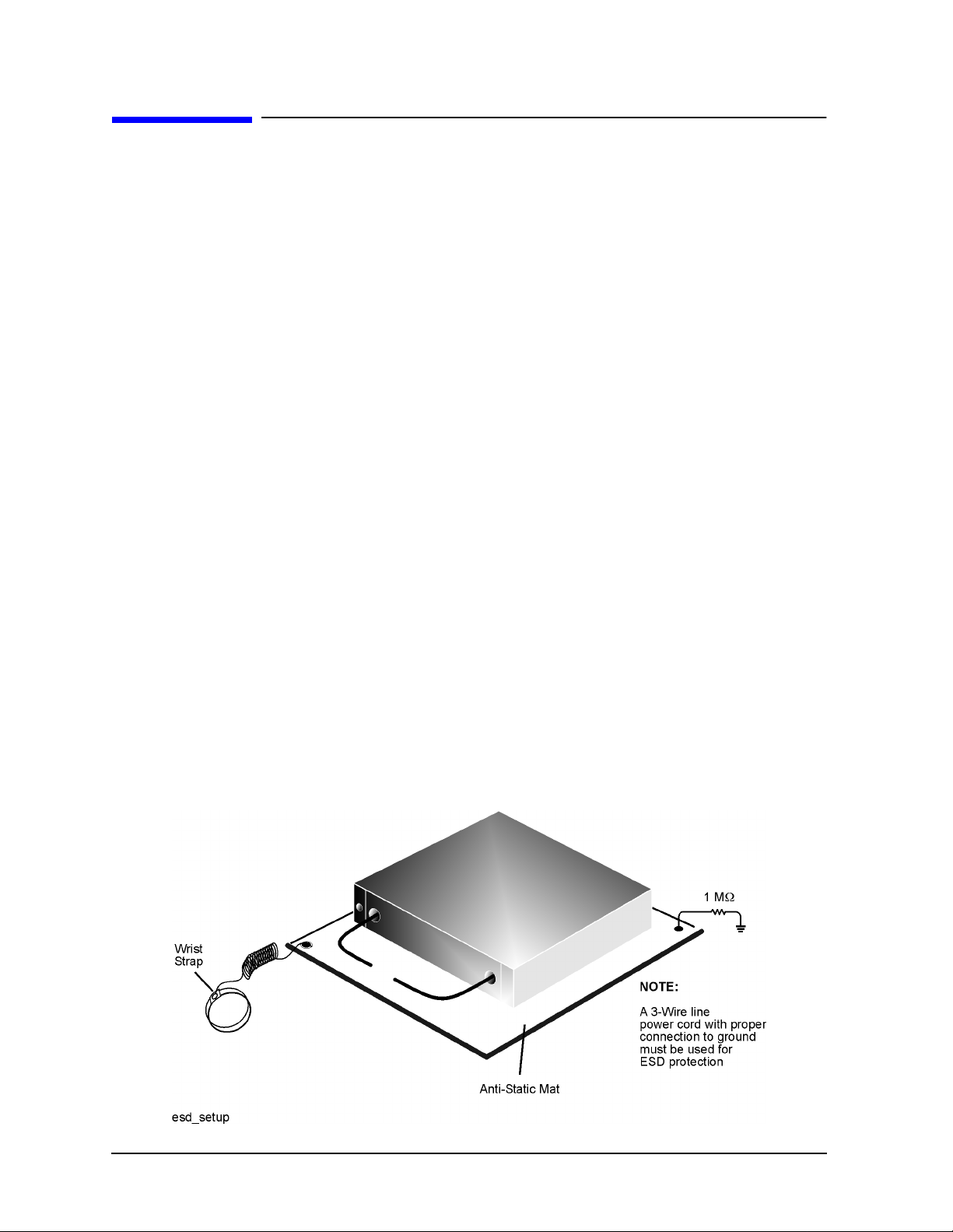
Electrostatic Discharge
Protection against ESD (electrostatic discharge) is essential while connecting, inspecting,
or cleaning connectors attached to a static-sensitive circuit (such as those found in test
sets).
Static electricity can build up on your body and can easily damage sensitive internal
circuit elements when discharged. Static discharges too small to be felt can cause
permanent damage. Devices such as calibration components and devices under test
(DUTs), can also carry an electrostatic charge. To prevent damage to the test set,
components, and devices:
• always wear a grounded wrist strap having a 1 MΩ resistor in series with it when
handling components and devices or when making connections to the test set.
• always use a grounded, conductive table mat while making connections.
• always wear a heel strap when working in an area with a conductive floor. If you are
uncertain about the conductivity of your floor, w ear a heel strap.
• always ground yourself before you clean, inspect, or make a connection to a
static-sensitive dev ice or tes t port. You can, for example, grasp t he ground ed outer s hel l
of the test port or cable connector briefly.
• always ground the center conductor of a test cable before making a connection to the
analyzer test port or other static-sensitive device. This can be done as follows:
1. Connect a short (from your calibration kit) to one end of the cable to short the center
conductor to the outer conductor.
2. While wearing a grounded wrist strap, grasp the outer shell of the cable connector.
3. Connect the other end of the cable to the test port.
4. Remove the short from the cable.
Refer to Chapter 6 , “Replaceable Parts,” for part numbe rs and instructions for orde ring
ESD protection devices.
Figure 3-1 ESD Protection Setup
3-2 85054B
Page 21

Use, Maintenance, and Care of the Devices
Visual Inspection
Visual Inspection
Visual inspection and, if necessary, cleaning should be done every time a connection is
made. Metal particles from the connector threads may fall into the connector when it is
disconnected. One connection made with a dirty or damaged connector can damage both
connectors beyond repair.
In some cases, magnification is necessary to see damage on a connector; a magnifying
device with a magnification of ≥10× is recommended. However, not all defects that are
visible only under magnification wi ll affect the elec trical per formance of the connector. Use
the following guidelines when evaluating the integrity of a connector.
Look for Obvious Defects and Damage First
Examine the connectors first for obvious defects and damage: badly worn plating on the
connector interface, deformed threads, or bent, broken, or misaligned center conductors.
Connector nuts should move smoothly and be free of burrs, loose metal particles, and
rough spots.
What Causes Connector Wear?
Connector wear is caused by connecting and disconnecting the devices. The more use a
connector gets, the faster it wears and degrades. The wear is greatly accelerated when
connectors are not kept clean, or are connected incorrectly.
Connector wear eventually d egra des performance of the dev ic e. Calibration devi ce s should
have a long life if their use is on the order of a few times per week. Replace devices with
worn connectors.
The test port connectors on the network analyzer test s et may have many connections each
day, and are therefore more subject to wear. It is recommended that an adapter be used as
a test port saver to minimize the wear on the test set’s test port connectors.
Inspect the Mating Plane Surfaces
Flat contact between the connectors at a ll point s on their mating plane sur faces is required
for a good connection. See Figure 2-1 on page 2-3. Look especially for deep scratches or
dents, and for dirt and metal particles on the connector mating plane surfaces. Also look
for signs of damage due to excessive or uneven wear or misalignment.
Light burnishing of the mating plane surfaces is normal, and is evident as light scratches
or shallow circular marks distributed more or less uniformly over the mating plane
surface. Other small defects and cosmetic imperfections are also normal. None of these
affect electrical or mechanical performance.
If a connector shows deep scratches or dents, particles clinging to the mating plane
surfaces, or uneven wear, clean and inspect it again. Devices with damaged connectors
should be discarded. Determine the cause of damage before connecting a new, undamaged
connector in the same configuration.
85054B 3-3
Page 22

Use, Maintenance, and Care of the Devices
Cleaning Connectors
Inspect the Precision Slotless Connectors (female)
Precision slotle ss female connectors are used to improve acc uracy. The slotless contacts are
not affected by the slight variations in male contact pin diameter. However, it is still
advisable to inspect them regularly for damage.
NOTE This is particularly impor tant when mating nonprecision to p recision devic es .
Cleaning Connectors
Clean connectors are essential for ensuring the integrity of RF and microwave coaxial
connections.
1. Use Compressed Air or Nitrogen
WARNING Always use protective eyewear when using compressed air or
nitrogen.
Use compressed air (or nitrogen) to loosen particles on the connector mating plane
surfaces.
You can use any source of clean, dry, low-pressure compressed air or nitrogen that has
an effective oil-vapor filter and liquid condensation trap placed just before the outlet
hose.
Ground the hose nozzle to prevent electrostatic discharge, and set the air pressure to
less than 414 kP a (60 ps i) to con trol the vel ocity of th e air stream. High- velocity s treams
of compressed air can cause electrostatic effects when directed into a connector. These
electrostatic effects can damage the device . Refe r to “Electrostatic Discha r ge” earlier in
this chapter for additional information.
2. Clean the Connector Threads
WARNING Keep isopropyl alcohol away from heat, sparks, and flame. Store in a
tightly closed container. It is extremely flammable. In case of fire, u se
alcohol foam, dry chemical, or carbon dioxide; water may be
ineffective.
Use isopropyl alcohol with adequate ventilation and avoid contact
with eyes, skin, and clothing. It causes skin irritation, may cause eye
damage, and is harmful if swallowed or inhaled. It may be harmful if
absorbed through the skin. Wash thoroughly after handling.
In case of spill, soak up with sand or earth. Flush spill area with
water.
Dispose of isopropyl alcohol in accordance with all applicable
federal, state, and local environmental regulations.
3-4 85054B
Page 23

Use, Maintenance, and Care of the Devices
Cleaning Connectors
Use a lint-free swab or cleaning cloth moistened with isopropyl alcohol to remove any
dirt or stubborn contaminants on a connector that cannot be removed with compressed
air or nitrogen. Refer to T abl e 6-2 on page 6-4 for part numbers f or isopropy l alcohol and
cleaning swabs.
a. Apply a small amount of isopropyl alcohol to a lint-free cleaning swab.
b. Clean the connector threads.
c. Let the alcohol evaporate, then blow the threads dry with a gentle stream of clean,
low-pressure compressed air or nitrogen. Always completely dry a connector before
you reassemble or use it.
3. Clean the Mat ing Plane Surfaces
a. Apply a small amount of isopropyl alcohol to a lint-free cleaning swab.
b. Clean the center and outer conductor mating plane surfaces. Refer to Figu re 2-1 on
page 2-3. When cleaning a female connector, avoid snagging the swab on the center
conductor contact fingers by using short strokes.
c. Let the alcohol evaporate , then blow the connector dry wit h a gentle stream of clean,
low-pressure compressed air or nitrogen. Always completely dry a connector before
you reassemble or use it.
4. Inspect
Inspect the connector again to make sure that no particles or residue are present.
85054B 3-5
Page 24

Use, Maintenance, and Care of the Devices
Gaging Connectors
Gaging Connectors
The gages available from Agilent Technologies are intended for preventive maintenance
and troubleshooting purposes only. (See Table 6-1 on page 6-2 fo r part number
information.) They are effective in detecting excessive center conductor protrusion or
recession, and conductor damage on DUTs, test acces sories , and the c alibration kit devices .
Do not use the g a g es fo r precise pin depth measurements.
Connector Gage Accuracy
The connector gages are only capable of performing coarse measurements. They do not
provide the degree of accuracy necessary to precisely measure the pin depth of the kit
devices. This is partially due to the repeatabil ity uncertai nties that a re associated with the
measurement. Only the factory—through special gaging processes and electrical testing—
can accurately verify the mechanical characteristics of the devices.
With proper te chnique , however, the gages are useful in detecting gros s pin depth err ors on
device connectors. To achieve maximum accuracy, random errors must be reduced by
taking the average of at least three measurements having different gage orientations on
the connector. Even the resultant average can be in error by as much as ± 0.0001 inch due
to systematic (biasing) errors usually resulting from worn gages and gage masters. The
information in Table 2-2 on page 2-4 assumes new gages and gage masters. Therefore,
these systematic errors were not included in the uncertainty analysis. As the gages
undergo more use, the s ystematic er rors can bec ome more significa nt in the a ccuracy of the
measurement.
The measurement uncertainties (see Table 2-2 on page 2-4) are primarily a function of the
assembly materials and design, and the unique interaction each device type has with the
gage. Therefore, these uncertainties can vary among the different devices. For example,
note the difference between the uncertainties of the opens and shorts in Table 2-2.
The observed pin depth limits in Table 2-2 add these uncertainties to the typical factory
pin depth values to provide practical limits that can be referenced when using the gages.
See “Pin Depth” on page 2-3. Refer to “Kit Contents” on page 1-2 for more information on
the design of the calibration devices in this kit.
NOTE When measuring pin depth, the measured value (resultant average of three
or more measurements) is not the true value. Always compare the measured
value with the observed pin depth limits in Table 2-2 on page 2-4 to evaluate
the condition of device connectors.
3-6 85054B
Page 25

Use, Maintenance, and Care of the Devices
Gaging Connectors
When to Gage Connectors
Gage a connector at the following times:
• Prior to using a device for the first time: record the pin depth measurement so that it
can be compared with future r eadings. ( It will serve as a good troub leshooting tool when
you suspect damage may have occurred to the device.)
• If either visual inspection or electrical performance suggests that the connector
interface may be out of typical range (due to wear or damage, for example).
• If a calibration device is used by someone else or on another system or piece of
equipment.
• Initially after every 100 connections, and after that as often as experience indicates.
Reading the Connector Gage
The gage dial is divided into increments of 0.0001 inch and major divisions of 0.001 inch
(see Figure 3-2). For each revolution of the large dial, the smaller dial indicates a change of
0.01 inch. Use the small dial as the indicator of multiples of 0.01 inch. In most connector
measuring applications, this value will be zero.
When making a measurement, the gage dial indi cator will travel i n one of tw o directio ns. If
the center conductor is recessed from the zero reference plane, the indicator will move
counterclockwise to i ndicate the amount of recession, whi ch is re ad as a ne g ativ e val u e. I f
the center conductor protrudes, the indic ator will move clockwi se to indicate the amount of
protrusion, which is read as a positive value. Refer to “Pin Depth” on page 2-3 for
definitions of protrusion and recession.
Figure 3-2 Reading the Connector Gage
85054B 3-7
Page 26

Use, Maintenance, and Care of the Devices
Gaging Connectors
Gaging Procedures
Gaging Male Type-N Connectors
NOTE Always hold a connector gage by the gage barrel, below the dial indicator.
This gives the best stability, and improves measurement accuracy.
1. Select the proper gage for your connector. (Refer to Table 6-2 for gage part numbers).
2. Inspect and clean the gage, gage master, and device to be gaged. Refer to “Visual
Inspection” and “Cleaning Connectors” earlier in this chapter.
3. Zero the connector gage (refer to Figure 3-3):
a. While holding the gage by the barrel, and without turning the gage or the gage
master, screw the gage master connecting nut onto the male gage, just until you
meet resistance. Connect the nut finger tight. Do not overtighten.
b. Use the torque wrench recommended for use with this kit to tighten the connecting
nut to 135 N-cm (12 in-lb). Refer to “Connections” on page 3-16 for more information.
c. Loosen the dial lock screw on the gage and rotate the gage dial so that the pointer
corresponds to the correction value noted on the gage master. Do not adjust the gage
dial to zero, unless the correction value on the gage master is zero.
d. Tighten the dial lock screw and remove the gage master.
e. Attach and torque the gage master to the gage once again to verify that the setting is
repeatable. Remove the gage master.
4. Gage the device connector (refer to Figure 3 -3):
a. While holding the gage by the barrel, and without turning the gage or the device,
screw the connecting nut of the device being measured onto the gage, just until you
meet resistance. Connect the nut finger-tight. Do not overtighten.
b. Use the torque wrench recommended for use with this kit to tighten the connecting
nut to 135 N-cm (12 in-lb). Refer to “Connections” on page 3-16 for more information.
c. Gently tap the barrel of the gage with your finger to settle the gage reading.
d. Read the gage indicator dial. If the needle has moved clockwise , the center conductor
is protruding by an amount indicated by the black
numbers. If the needle ha s moved
counterclockwi se, the center conduct or is recessed by an amount indicated by the red
numbers.
For maximum accuracy, measure the connector a minimum of three times and take
an average of the readings. After each measurement, rotate the gage a quarter-turn
to reduce measurement variati ons that result f rom the gage or t he connector face not
being exactly perpendicular to the center axis.
e. Compare the average reading with the o bserved pin d epth limits i n T a ble 2-2 on page
2-4.
3-8 85054B
Page 27

Figure 3-3 Gaging Male Type-N Connectors
Use, Maintenance, and Care of the Devices
Gaging Connectors
85054B 3-9
Page 28

Use, Maintenance, and Care of the Devices
Gaging Connectors
Gaging Female Type-N Connectors
NOTE Always hold a connector gage by the gage barrel, below the dial indicator.
This gives the best stability, and improves measurement accuracy.
1. Select the proper gage for your connector. (Refer to Table 6-2 for gage part numbers).
2. Inspect and clean the gage, gage master, and device to be gaged. Refer to “Visual
Inspection” and “Cleaning Connectors” earlier in this chapter.
3. Zero the connector gage (refer to Figure 3-4):
a. While holding the gage by the barrel, and without turning the gage or the gage
master, screw the gage connecting nut onto the female gage master, just until you
meet resistance. Connect the nut finger-tight. Do not overtighten.
b. Use the torque wrench recommended for use with this kit to tighten the connecting
nut to 135 N-cm (12 in-lb). Refer to “Connect ions” on pag e 3-16 for more in fo rmation .
c. Loosen the dial lock screw on the gage and rotate the gage dial so that the pointer
corresponds to the correction value noted on the gage master. Do not adjust the gage
dial to zero, unless the correction value on the gage master is zero.
d. Tighten the dial lock screw and remove the gage master.
e. Attach and torque the gage master to the gage once again to verify that the setting is
repeatable. Remove the gage master.
4. Gage the device connector (refer to Figure 3-3 o n page 3-9 ):
a. While holding the gage by the barrel, and without turning the gage or the device,
screw the gage connecting nut onto the device being measured, just until you meet
resistance. Connect the nut finger-tight. Do not overtighten.
b. Use the torque wrench recommended for use with this kit to tighten the connecting
nut to 135 N-cm (12 in-lb). Refer to “Connections” on page 3-16 for more information.
c. Gently tap the barrel of the gage with your finger to settle the gage reading.
d. Read the gage indicator dial. If the needle has moved clockwise , the center conductor
is protruding by an amount indicated by the black
numbers. If the needle ha s moved
counterclockwi se, the center conduct or is recessed by an amount indicated by the red
numbers.
For maximum accuracy, measure the connector a minimum of three times and take
an average of the readings. After each measurement, rotate the gage a quarter-turn
to reduce measurement variati ons that result f rom the gage or t he connector face not
being exactly perpendicular to the center axis.
e. Compare the average reading with the o bserved pin d epth limits i n T a ble 2-2 on page
2-4.
3-10 85054B
Page 29

Figure 3-4 Gaging Female Type-N Connectors
Use, Maintenance, and Care of the Devices
Gaging Connectors
85054B 3-11
Page 30

Use, Maintenance, and Care of the Devices
Gaging Connectors
Gaging the Sliding Load
Gage the sliding load before each use. If the sliding load pin depth is out of the observed
pin depth limits listed in Table 2-2 on page 2-4, refer to “Adjusting the Sliding Load Pin
Depth” on page 3 -13.
NOTE Always hold a connector gage by the gage barrel, below the dial indicator.
This gives the best stability, and improves measurement accuracy. (Cradling
the gage in your hand or holding it by the dial applies stress to the gage
plunger mechanism through the dial indicator housing.)
NOTE The sliding load uses a plastic centering bead to support its center conductor
when pin depth is adjusted and gaged and when the load is stored. Remove
this support bead from the sliding load before you connect the load for an
electrical calibration. Reinsert this support bead when you’ve finished using
the sliding load.
1. Select the proper gage for your connector. Refer to “Replaceable Parts for the 85054B
Calibration Kit” on page 6-2 for gage part numbers.
2. Inspect and clean the gage, gage master, and device to be gaged. Refer to “Visual
Inspection” on page 3-3 and “Cleaning Connectors” on page 3-4 earlier in this chapter.
3. Zero the connector gage as described in either Step 3 on page 3-8 (for a male gage) or
Step 3 on page 3 -10 (for a female gage)
4. Remove the center conductor protective cap from the sliding load.
5. Loosen the center conductor pull-back nut completely, and press the center-conductor
cap to extend the center conductor beyond the end of the connector. With the sliding
ring pulled back approximately 0.5 inch, install a centering bead (if not already
installed) in the connector end of the sliding load.
6. Continue to pres s the c enter co nductor c ap and mate the c enter c ond uct or o f the s li ding
load with the gage’s center conductor.
CAUTION The sliding load center conductor can be damaged if the sliding load is not
held in line when mating the load to a connector. Always line up the sliding
load when connecting or removing it from a connector.
7. Mate the outer conductor of the sliding load with the outer conductor of the gage.
Torque the connection with a 3/4 inch torque wrench to approximately 135 N-cm
(12 in-lb). Retighten the center conductor pull-back nut. It will “click” when it is tight.
8. Gently tap the barrel of the gage with your finger to settle the gage reading.
9. Read the gage indicator dial . If the needle had moved clockwise, the ce nter conductor is
protruding and the value is determined by the black numbers. If the needle had moved
counterclockwise , the cente r conductor is recess ed by an amount determined by the red
numbers.
10.For maximum accuracy, measure the connector a minimum of three times and take an
average of the readings.
3-12 85054B
Page 31

Use, Maintenance, and Care of the Devices
Gaging Connectors
NOTE When performing pin depth measurements, use different orientations of the
gage within the connector. Averaging a minimum of three readings, each
taken after a quarter-turn rotation of the gage, reduces measurement
variations that result from the gage or the connector face not being exactly
perpendicular to the center axis.
11.Compare the average reading with the observed pin depth limits in Table 2-2 on page
2-4. If the pin depth is outside the limits, follow the procedure “Adjusting the Sliding
Load Pin Depth.”
12.Loosen the connection between the gage and the sliding load, and remove the sliding
load from the gage.
13.Leave the centering bead installed on the sliding load if you are going to adjust the pin
depth. Carefully remove the cente ring bead from the sli ding load if you’ re going to use it
for an electrical calibration. If the centering bead does not come out of the sliding load
easily, loosen the center conductor pull-back nut, and press the center conductor cap to
extend the center conductor. This should expose the centering bead so that it may be
removed. Retract the center conductor and retighten the pull-back nut.
If the centering bead still will not come out, hold the sliding load with the connector end
pointed down. Move the sliding element up, then quickly down. The trapped air behind
the centering bead helps eject it.
CAUTION Damage can occur to the sliding load during the removal of a centering bead
that has slipped too far into the sliding load. If you’re going to perform an
electrical calibration, prevent damage by removing the centering bead
immediately after gaging the sliding load pin depth. The sliding load will not
perform to its specifications if the centering bead is not removed from the
sliding load befo re an electrical calibration .
Figure 3-5 Gaging the Sliding Load Pin Depth
Adjusting the Sliding Load Pin Depth
The sliding loads in this kit have a setback mechanism that allows the pin depth to be set
to any desired value. The pin depth of the sliding load is preset at the factory. The pin
depth should not have to be reset e ach ti me the sliding loa d is used, but it should be chec ked
before e ach u se.
85054B 3-13
Page 32

Use, Maintenance, and Care of the Devices
Gaging Connectors
If the pin depth is outside the observed limits listed in Table 2-2 on page 2-4, use the
following procedur e to reset it. Alwa y s me asur e the sliding load pi n d ept h b efo re att achi ng
it to any connector.
This procedure assumes that you were directed here from “Gaging the Sliding Load” on
page 3-12. If not, perform the steps in that procedure before performing this procedure.
1. The gage should be attached to the sliding load. The sliding load should have its
centering bead installed. Refer to “Gaging the Sliding Load” on page 3-12 if necessary.
2. With a 0.050 inch hex key, loosen the two large st hex screws by turning them 1/4 turn
clockwise. Refer to Figure 3-6.
CAUTION Do not loosen any hex screws other than the two largest hex screws pointed
out in Figure 3-6.
3. Gently turn the center conductor pin depth adjustment knob on the sliding load until
–4
the gage pointer reads −3.81 micrometers (−1.5 x 10
inches). Refer to Figu re 3-6.
4. Tighten the two hex screws just until they are finger tight (do not overtighten).
5. Wait approximately five minutes to allow the temperature to stabilize. Do not touch
either the gage or the sliding load during this time.
6. Note the gage reading. If it is no longer within the allowable range, perform steps 2–5
again.
7. Loosen the connecting nut and remove the gage from the sliding load. If you’re going to
store the sliding load, leave the centering bead installed. If you’re gong to use the
sliding load for an electrical calibration, remove the centering bead.
NOTE When performing pin depth measurements, use different orientations of the
gage within the connector. Averaging a minimum of three readings, each
taken after a quarter-turn rotation of the gage, reduces measurement
variations that result from the gage or the connector face not being exactly
perpendicular to the center axis.
The sliding load pin depth is now is specification and the load is ready to use. Once the
sliding load pin depth is set it rarely needs to be adjusted. However, the pin depth should
be rechecked before each use. Replace the protective plastic caps on the sliding load and
gage connectors when these devices are not in use.
3-14 85054B
Page 33

Figure 3-6 Adjusting the Sliding Load Pin Depth
Use, Maintenance, and Care of the Devices
Gaging Connectors
85054B 3-15
Page 34

Use, Maintenance, and Care of the Devices
Connections
Connections
Good connections require a skill ed op erator. The most comm o n caus e of me asu rement error
is bad connections. The following procedures illustrate how to make good connections.
How to Make a Connection
Preliminary Connection
1. Ground yourself and all devices. Wear a grounded wrist strap and work on a grounded,
conductive table mat. Refer to “Electrostatic Discharge” on page 3-2 for ESD
precautions.
2. Visually inspect the connectors. Refer to “Visual Inspection” on page 3-3.
3. If necessary, clean the connectors. Refer to “Cleaning Connectors” on page 3 -4.
4. Use a connector gage to verify that all center conductors are within the observed pin
depth values in Table 2-2 on pa ge 2-4. Refer to “Gaging Connectors” on page 3-6.
5. Carefully align the connectors. The male connector center pin must slip concentrically
into the contact finger of the female connector.
6. Push the connectors straight together.
CAUTION Do not turn the device body. Only turn the connector nut. Damage to the
center conductor can occur if the device body is twisted.
Do not twist or screw the connectors together. As the center conductors mate, there is
usually a slight resistance.
7. The preliminary connection is tight enough when the mating plane surfaces make
uniform, light contact. Do not overtighten this connection.
A connection in which the outer conductors make gentle contact at all points on both
mating surfaces is sufficient. Very light finger pressure is enough to accomplish this.
8. Make sure the connectors are properly supported. Relieve any side pressure on the
connection from long or heavy devices or cables.
Final Connection Using a Torque Wrench
Use a torque wrench to make a final connection. T able 3-1 provides information about the
torque wrench recommended for use with this calibration kit. A torque wrench is not
included in the calibrat ion kit. Refer to Chapter 6 “Replaceable Parts” for part number and
ordering i n fo rmation.
Table 3-1 Torque Wrench Information
Connector Type Torque Setting Torque Tolerance
Type-N 135 N-cm (12 in-lb) ±13.5 N-cm (±1.2 in-lb)
3-16 85054B
Page 35

Use, Maintenance, and Care of the Devices
Connections
Using a torque wrench guarantees that the c onnec tion is not too tight, prev enting possible
connector damage. It also guarantees that all connections are equally tight each time.
Prevent the rotation of anything other than the connector nut that you are tightening. It
may be possible to do this by hand if one of the connect ors i s fi xed (as on a test port ). In all
situations, however, it is recommended that you use an open-end wrench to keep the body
of the device from turning. Refer to Chapter 6 for part number and or de rin g in fo rmatio n .
1. Position both wrenches within 90 degrees of each other before applying force. See
Figure 3-7 . Wrenches opposing each other (greater than 90 degrees apart) will cause a
lifting action which can misalign and stress the connections of the devices involved.
This is especially true when several devices are connected together.
Figure 3-7 Wrench Positions
2. Hold the torque wrench lightly, at the end of the handle only (beyond the groove). See
Figure 3-8 .
Figure 3-8 Using the Torque Wre n ch
85054B 3-17
Page 36

Use, Maintenance, and Care of the Devices
Connections
3. Apply downwa rd fo rce perpendicular t o the wrench handle. See Figu re 3-8. This applies
torque to the connection through the wrench.
Do not hold the wrench so tightly that you push the handle straight down along its
length rather than pivoting it, otherwise you apply an unknown amount of torque.
4. Tighten the connection just to the torque wrench break point. The wrench handle gives
way at its internal pivot point. See Figure 3-8. D o not tighten the connection further.
CAUTION You don’t have to fully break the handle of the torque wrench to reach the
specified torque; doing so can cause the handle to kick back and loosen the
connection. Any give at all in the handle is sufficient torque.
Do not pivot the wrench handle on your thumb or other fingers , other wis e you apply an
unknown amount of torque to the connection when the wrench reaches its break point.
Do not twist the head of the wrenc h r el ative to the outer conductor mating pla ne. If you
do, you apply more than the recommended torque.
Connecting the Sliding Load
Use this procedure to connect the sliding load to a test port or a type-N cable connector.
NOTE The sliding load uses a plastic centering bead to support its center conductor
when pin depth is adjusted and gaged and when the load is stored. Remove
this support bead from the sliding load before you connect the load for an
electrical calibration. Reinsert this support bead when you’ve finished using
the sliding load.
CAUTION Circuitry inside the test set at the test ports may be destroyed if precautions
are not taken to avoid electrostatic discharge (ESD). During this procedure,
the center conductor of the sliding load is connected to the exposed center
conductor of the test port. Ground yourself to prevent electrostatic discharge.
CAUTION The sliding load center conductor can be damaged if the sliding load is not
held in line when mating the load to a connector. Always line up the sliding
load when connecting or removing it from a connector.
1. Refer to Figure 3- 9. Loosen the center conductor pull-back nut completely. Press the
center conductor cap to extend the center c onductor of the sliding loa d beyond the end of
the connector.
2. Continue to pres s the c enter co nductor c ap and mate the c enter c ond uct or o f the s li ding
load with the cable/test port connector’s center conductor.
3-18 85054B
Page 37

Use, Maintenance, and Care of the Devices
Connections
3. Release pressure on the center conductor and mate the outer conductor of the sliding
load with the outer conductor of the cable/test port connector. Torque the connection
with a 3/4 inch torque wrench to approximately 135 N-cm (12 in-lb). Refer to “Final
Connection Using a Torque Wrench” on page 3-16 for additiona l in format io n .
4. Retighten the center conductor pull-back nut. It will “click” when it is tight.
Figure 3-9 Connecting the Sliding Load
How to Separate a Connection
To a void l ateral (bending) f orce on the connecto r mating plane surf aces, alw ays support the
devices and connections.
CAUTION Turn the connector nut, not the device body. Major damage to the center
conductor can occur if the device body is twisted.
1. Use an open-end wrench to prevent the device body from turning.
2. Use another open-end wrench to loosen the connector nut.
3. Complete the separation by hand, turning only the connector nut.
4. Pull the connectors straight apart without twisting, rocking, or bending either of the
connectors.
85054B 3-19
Page 38

Use, Maintenance, and Care of the Devices
Using the Sliding Load
Using the Sliding Load
When performing a sliding load calibration, it is recommended that the sliding ring be set
at the marked positions (rings) along the sliding load body. Using the set marks ensures
that a broad distribution of phase angles is selected, thereby optimizing the calibration.
The set marks function as detents so that the internal center of the sliding ring can mate
with them. Because of this , the set m ark being used cannot be seen bu t is felt as the sliding
ring is moved from mark to mark during a calibration. Moving the sliding ring with only
the index fingers of bot h hands will i ncrease your abi lity to det ect the slid ing ring detent at
each position.
To perfor m a sliding l oad cali bration, r efer to y our network analyzer s user’ s documentation
for instr u ct io n s.
3-20 85054B
Page 39

Figure 3-10 Using the Sliding Load
Use, Maintenance, and Care of the Devices
Using the Sliding Load
85054B 3-21
Page 40

Use, Maintenance, and Care of the Devices
Handling and Storage
Handling and Storage
• Install the protective end caps and store the calibration devices in the foam-lined
storage case when not in use.
• Never store connectors loose in a box, desk, or bench drawer. This is the most common
cause of connector damage during storage.
• Keep connectors clean.
• Do not touch mating plane surfaces. Natural skin oils and microscopic particles of dirt
are easily transferred to a connector interface and are very difficult to remove.
• Do not set connectors contact-end down on a hard surface. The plating and the mating
plane surfaces can be damaged if the interface comes in contact with any hard surface.
3-22 85054B
Page 41

4 Performance Verification
4-1
Page 42

Performance Verification
Introduction
Introduction
The performance of your calibra tion kit can only be verified b y retur ning the kit to Agi len t
Technologies for recertification. The equipment required to verify the specifications of the
devices in the kit has been specially manufactured and is not commercially available.
How Agilent Verifies the Devices in This Kit
Agilent verifies the specifications of these devices as follows:
1. The residual microwave error terms of the test system are verified with precision
airlines and shorts that are directly traced to NIST (National Institute of Standards
and Technology). Th e airline and sh o rt characterist ics are develo pe d fro m mechan ical
measurements. The mechanical measurements and material properties are carefully
modeled to give very accurate electrical representa tion. The mechanical measurements
are then traced to NIST through various plug and ring gages and other mechanical
measurements.
2. Each calibration device is electrically tested on this system. For the initial (before sale)
testing of the ca li brat ion de vi ces , Agilent inc ludes the test measurement unc er tainty a s
a guardband to guarantee each device meets the published specification. For
recertifications (after sale), no guardband is used and the measured data is compared
directly with the specification to determine the pass or fail status. The measurement
uncertainty for each device is, however, recorded in the calibration report that
accompanies recertified k it s.
These two steps establish a traceable link to NIST for Agilent to the extent allowed by the
institute’s calibration facility. The specifications data provided for the devices in this kit is
traceable to NIST through Agilent Technologies.
4-2 85054B
Page 43

Perf ormance Verification
Recertification
Recertification
The following will be provided with a recertified kit:
• a new calibration sticker affixed to the case
• a certificate of calibrat i on
• a calibration report for each device in the kit listing measured values, specifications,
and uncertainties
NOTE A list of NIST traceable numbers may be purchased upon request to be
included in the calibration report.
Agilent Technologies offers a Standard calibration for the recertification of this kit. For
more information, contact Agilent Technologies. For contact information, see page5-3.
How Often to Recertify
The suggested initial inter val fo r recertifi cation i s 12 months or sooner. The actual need for
recertification depends on the use of the kit. After reviewing the results of the initial
recertification, you may establi sh a different recertif ication inter val that reflects the usage
and wear of the kit.
NOTE The recertification interva l should begin on the date the kit is first used after
the recertification date.
Where to Send a Kit for Recertification
Contact Agilent Technologies for information on where to send your kit for recertification.
For contact information, refer to page 5-3.
When you return the kit, complete and attach a service tag. Refer to “Returning a Kit or
Device to Agilent” on page 5-3 for details.
85054B 4-3
Page 44

Performance Verification
Recertification
4-4 85054B
Page 45

5 Troubleshooting
5-1
Page 46

Troubleshooting
T roubleshooting Process
Troubleshooting Process
If you suspect a bad calibration, or if your network analyzer does not pass performance
verification, follow the steps in Figure 5-1.
Figure 5-1 Troubleshooting Flowchart
5-2 85054B
Page 47

Troubleshooting
Returning a Kit or Device to Agilent
Returning a K it or Device to Agilent
If your kit or device requires service, contact Agilent Technologies for information on
where to send it. See Table 5-1 for contact information. Include a service tag (located near
the end of this manual) on which you provide the following information:
• your company name and address
• a technical contact person within your company, and the person's complete telephone
number
• the model number and serial number of the kit
• the part number and serial number of each device
• the type of service required
•a detailed description of the problem and how the device was being used when the
problem occurred (such as calibration or measurement)
Where to Look for More Information
This manual contains limited information about network analyzer system operation. For
complete information, refer to the instrument documentation. If you need additional
information, contact Agilent Technologies.
Contacting Agilent
Table 5-1 Contacting Agilent
Online assistance: www.agilent.com/find/assist
United States
(tel) 1 800 452 4844
New Zealand
(tel) 0 800 738 378
(fax) (+64) 4 495 8950
Malaysia
(tel) 1 800 828 848
(fax) 1 800 801 664
Latin America
(tel) (305) 269 7500
(fax) (305) 269 7599
Japan
(tel) (+81) 426 56 7832
(fax) (+81) 426 56 7840
Philippines
(tel) (632) 8426802
(tel) (PLDT subscriber
only):
1 800 16510170
(fax) (632) 8426809
(fax) (PLDT subscriber
only):
1 800 16510288
Canada
(tel) 1 877 894 4414
(fax) (905) 282-6495
Australia
(tel) 1 800 629 485
(fax) (+6 1) 3 9210 5947
Thailand
(tel) outside Bang ko k:
(088) 226 008
(tel) with in Bangko k :
(662) 661 3999
(fax) (66) 1 661 3714
Europe
(tel) (+31) 20 547 2323
(fax) (+31) 20 547 2390
Singapore
(tel) 1 800 375 8100
(fax) (65) 836 0252
Hong Kong
(tel) 800 930 871
(fax) (852) 2506 9233
Taiwan
(tel) 0800-047-866
(fax) (886) 2 25456723
People’s Republic of
China
(tel) (preferred ):
800-810-0189
(tel) (alternate):
10800-650-0021
(fax) 10800-650-0121
India
(tel) 1-600-11-2929
(fax) 000-800-650-1101
85054B 5-3
Page 48

Troubleshooting
Returning a Kit or Device to Agilent
5-4 85054B
Page 49

6 Replaceable Parts
6-1
Page 50

Replaceable Parts
Introduction
Introduction
Table 6-1 lists the replacement part numbers for items included in the 85054B calibration
kit and Figure 6-1 illustrates each of these items.
Table 6-2 lists the replacement part numbers for items recommended or required for
successful operation but not included in the calibration kit.
To order a listed part, note the description, the part number, and the quantity desired.
Refer to “Contacting Agilent” on page 5-3.
Table 6-1 Re plac eab le Parts for the 85054B Calibration Kit
Item No. Description Qty Per
Kit
Calibration Devices (50Ω Type-N)
1 Type-N (m) sliding loa d 1 85054-60035
2 Type-N (f) sliding load 1 85054-60036
3 Type-N (m) lowband load 1 00909-60011
4 Type-N (f) lowband load 1 00909-60012
5 Type-N (m) offs et short 1 85054-60025
6 Type-N (f) offset short 1 85054-60026
7 Type-N (m) offs et open 1 85054-60027
8 Type-N (f) offset open 1 85054-60028
Adapters
9 Type-N (m) to Type-N (m) 1 85054-60038
10 Type-N (f) to Type-N (f) 1 85054-60037
11 Type-N (f) to 7 mm 2 85054-60031
12 Type-N (m) to 7 mm 2 85054-60032
Agilent Part Number
Wrenches
13
14 Spanner 1 08513-20014
15 Storage Case Assembly (includes items listed below) 1 85054-60039
16 Box 1 5180-7900
17 ID label 1 85054-80012
18 Foam pad (bottom) 1 85054-80023
19 F oam pad (lid) 1 5181-5543
3/4 in., 135 N-cm (12 in-lb) Torque
Calibration Kit Storage Case
1 8710-1766
6-2 85054B
Page 51

Table 6-1 Replaceable Parts for the 85054B Ca libration Kit
Replaceable Parts
Introduction
Item No. Description Qty Per
Kit
20 Disk holder 1 5180-8491
Gages
21 Screw-on N Gage 1 85054-80011
22 Type-N gage set (includes items listed below) 1 85054-60049
23 Type-N gage (f) 1 85054-60050
24 Type-N gage master (f) 1 85054-60052
25 Type-N gage (m) 1 85054-60051
26 Type-N gage master (m) 1 85054-60053
27 Centering beads 2 85054-80028
Miscellaneous Items
28 User’s and service guide 1 85054-90049
29 Calibration definitions disk (PNA) 1 85054-10007
30 Calibration definitions disk (8510, 872x series) 1 85054-10005
31
Specifications & Performance Verifi cation Disk
a
1 85010-10033
Agilent Part Number
32 Prote ctive En d Cap (f) as
required
33 Protective End Cap (m & 7 mm) as
required
34 Connector Care–Quick Reference Card 1 08510-90360
1401-0225
1401-0208
a. See the 8510C On-Site S ervice Manual for i nstructions on using this disk.
85054B 6-3
Page 52

Replaceable Parts
Introduction
Table 6-2 Replaceable Parts—Items Not Included in the Calibration Kit
Item No. Descript ion Qty Agilent Part Number
Wrenches
1 1/2 in and 9/16 in open-end wrench 1 8710-1770
2 3/4 in open-end wrench 1 8720-0011
Adapters
3 50 ohm (m) Type-N to 7 mm (ex tendable/retractable sleeve) 1 85054-60009
4 50 ohm (f) Type-N to 7 mm (extendable/retractable sleeve) 1 85054-60001
ESD Protective Devices
5 Grounding wrist str ap 1 9300-1367
6 5 ft grounding cord for wrist strap 1 9300-0980
7 2 ft by 4 ft conductive table mat with 15 ft grounding wire 1 9300-0797
8 ESD heel strap 1 9300-1126
Connector Cleaning Supplies
9 Isopropyl alcohol 30 ml 8500-5344
10 Foam tipped cleaning swabs 100 9301-1243
6-4 85054B
Page 53

Figure 6-1 Replaceable Parts for the 85054B Calibration Kit
Replaceable Parts
Introduction
85054B 6-5
Page 54

Replaceable Parts
Introduction
Figure 6-2 More Replaceable Parts for the 85054B Calibration Kit
6-6 85054B
Page 55

A Standard Definitions
85054B A-1
Page 56

Standard Definitions
Version Changes
Version Changes
Class assignments and standard definitions may change as more accurate model and
calibration methods are developed. The disk shipped with the kit will contain the most
recent version.
A-2 85054B
Page 57

Standard Definitions
Standard Class Assignments
Standard Class Assignments
Class assignment organizes calibration standards into a format compatible with the error
models used in the measurement calibration. A class or group of classes corresponds to the
systematic errors to be removed from the measured network analyzer response. Table A-1
through A-3 list the classes of the devices in the kit for various network analyzers. This
information resides on the calibration definitions disk included in the kit.
Table A-1 Standard Class Assignments for the 8510 Network Analyzer
Disk File Name: CK_NTYPB2 Calibration Kit Label: TYPE N B.2
File Number: * FILE 1
Class A B C D E F G Standard Class Label
A24 Open
S
11
S
B13 Short
11
S
C 9 10 12 Loads
11
S
A24 Open
22
S
B13 Short
22
S
C 9 10 12 Loads
22
Forward transmission 11 Thru
Reverse transmission 11 Thru
Forward match 11 Thru
Reverse match 11 Thru
Forward isolation
Reverse isolation 9 Isol’n Std
Frequency response 132411 Response
TRL thru 14 Undefined
TRL reflect 1 Undefined
TRL line 15 Undefined
Adapter 13 14 Adapter
TRL Option
a
9 Isol’n Std
Cal Z
: _____ System Z0 __X__ Line Z
0
Set ref: __X__ Thru _____ Reflect
Lowband frequency: 2.0 GHz
a. The forward isolation standard is also used for the isolation part of the response and isolation
calibration.
0
85054B A-3
Page 58

Standard Definitions
Standard Class Assignments
Table A-2 Standard Class Assignments for the 872x Series Network Analyzer
Calibration Kit Label: [N 50 Ω]
Class A B C D E F G Standard Class Label
S11A
S11B
S11C
S22A
S22B
S22C
Forward transmission 4 Thru
Reverse transmission 4 Thru
For wa rd ma tc h 4 Thr u
Reverse match 4 Thru
Response 17284 Response
Response & isolation 17284 Response
TRL thru 4 Thru
TRL reflect 2 8 Open
TRL line or match 3 5 6 Loads
28 Open
17 Short
356 Loads
28 Open
17 Short
356 Loads
TRL Option
Cal Z0: _____ System Z0 __X__ Line Z
Set ref: __X__ Thru _____ Reflect
0
A-4 85054B
Page 59

Standard Definitions
Standard Class Assignments
Table A-3 Standard Class Assignments for the PNA Series Network Analyzer
Calibration Kit Label:
T ype-N Model 85054B
S
11
S11B
S11C
S21T
S22A
S22B
S22C
S12T
Class
A
Aa
2
1
3, 5, 6
4
2
1
3, 5, 6
4
a. For ad dition al por ts , make sur e
values match the correct sex of
the port.
IMPORTANT The following calibrations are only supported by certain PNA analyzers. See
your PNA series network analyzer embedded help system.
Notes:
1. If you are performing a TRL calibration:
•S
•S
•S
T and S12T must be defi n ed as th ru st andards.
21
A and S22A must be defined as reflection standards.
11
B, S11C, S22B, and S22C must be defined as line stan dards.
11
2. If you are performing a TRM calibration:
•S
•S
•S
T and S12T must be defi n ed as th ru st andards.
21
A and S22A must be defined as reflection standards.
11
B, S11C, S22B, and S22C must be defined as match standards.
11
3. If you are performing an LRM calibration:
•S
•S
•S
T and S12T must be defi n ed as lin e standards.
21
A and S22A must be defined as reflection standards.
11
B, S11C, S22B, and S22C must be defined as match standards.
11
85054B A-5
Page 60

Standard Definitions
Standard Class Assignments
4. S11B and S11C must be defined as the same standard.
5. S
B and S22C must be defined as the same standard.
22
For additional information on performing TRL, TRM, and LRM calibrations, refer to your
PNA series network analyzer embedded help system.
A-6 85054B
Page 61

Standard Definitions
Standard Class Assignments
Blank Forms
The standard class assignments may be changed to meet your specific requirements. Table
A-4 through A-6 are provided to record the modified standard class assignments.
Table A-4 Blank Form for the 8510 Network Analyzer
Disk File Name: _______________________
Calibration Kit Label: _________________
File Number:
Class A B C D E F G Standard Class Label
S11A
S
B
11
S
C
11
S
A
22
S
B
22
S
C
22
Forward transmission
Reverse transmission
Forward match
Reverse match
Forward isolation
Reverse isolation
a
Frequency response
TRL thru
TRL reflect
TRL line
Adapter
TRL Option
Cal Z0: _____ System Z
Set ref: _____ Thru _____ Reflect
Lowband frequency
a. The forward isolation standard is also used for the isolation part of the response and isolation calibration.
b. Broadband loads are used for frequencies up to 2 GHz.
b
: ___________
0
_____ Line Z
0
85054B A-7
Page 62

Standard Definitions
Standard Class Assignments
Table A-5 Blank Form for the 872x Series of Network Analyzers
Calibration Kit Label: _________________
Class A B C D E F G Standard Class Label
S11A
S
B
11
S
C
11
S
A
22
S
B
22
S
C
22
Forward transmission
Reverse transmission
For wa rd ma tc h
Reverse match
Response
Response & isolation
TRL thru
TRL reflect
TRL line or match
TRL Option
Cal Z0: _____ System Z0 _____ Line Z
Set ref: _____ Thru _____ Reflect
0
A-8 85054B
Page 63

Standard Class Assignments
Table A-6 Blank Form for the PNA Series Network Analyzers
Calibration Kit Label:
________ ___________ _____
Standard Definitions
Class
S
A
11
S
B
11
S
C
11
S
T
21
S
A
22
S
B
22
S
C
22
S
T
12
a.
For ad dition al ports, make sure
values match the correct sex of
the port.
Aa
IMPORTANT The following calibrations are only supported by certain PNA analyzers. See
your PNA series network analyzer embedded help system.
Notes:
1. If you are performing a TRL calibration:
•S
•S
•S
T and S12T must be defi n ed as th ru st andards.
21
A and S22A must be defined as reflection standards.
11
B, S11C, S22B, and S22C must be defined as line stan dards.
11
2. If you are performing a TRM calibration:
•S
•S
•S
T and S12T must be defi n ed as th ru st andards.
21
A and S22A must be defined as reflection standards.
11
B, S11C, S22B, and S22C must be defined as match standards.
11
3. If you are performing an LRM calibration:
•S
•S
•S
T and S12T must be defi n ed as lin e standards.
21
A and S22A must be defined as reflection standards.
11
B, S11C, S22B, and S22C must be defined as match standards.
11
85054B A-9
Page 64

Standard Definitions
Standard Class Assignments
4. S11B and S11C must be defined as the same standard.
5. S
B and S22C must be defined as the same standard.
22
For additional information on performing TRL, TRM, and LRM calibrations, refer to your
PNA series network analyzer embedded help system.
A-10 85054B
Page 65

Standard Definitions
Nominal Standard Definitions
Nominal Standard Definitions
Standard definitions provide the constants needed to mathematically model the electrical
characteristics (delay, attenuation, and impedance) of each calibration standard. The
nominal values of these constants are theoretically derived from the physical dimensions
and material of each calibr ation standard, o r from actual measured re sponse. T hese values
are used to determine the measurement uncertainties of the network analyzer. The
standard definitions in Table A-7 thro ugh A-9 list typical calibration kit parameters used
to specify the mathematical model of each device . This information must be loaded into the
network analyzer to perform valid calibrations. Refer to your network analyzer user’s
guide for instructions on loading calibration definitions.
NOTE The values in the standard definitions table are valid only over the specified
operating temperature range.
Setting the System Impedance
This kit contains only 50 ohm devices. Ensure the system impedance (Z0) is set t o 5 0 ohms .
Refer to your network analyzer’s user’s gui de for instructions on setting system impedance .
85054B A-11
Page 66

Standard Definitions
Nominal Standard Definitions
Table A-7 Standard Definitions for the 8510 Network Analyzer
System Z
a
= 50.0
0
Disk File Name:
Standard
Number
1
2
3
4
b
Type
e
Short
e104.13−1943.4
Open
e 0.7563 459.88−52.429 1.5846 63.078 50 1.1273 0 999 Coax
Short
e 89.939 2536.8−264.99 13.4 57.993 50 0.93 0 999 Coax
Open
Ω
CK_NTYPB2
F
−15
10
×
C0
H
−12
10
×
L0
0.1315
−
F/Hz
−27
10
×
C1
H/Hz
−24
10
×
L1
606.21 −
2
F/Hz
−36
10
×
C2
2
H/Hz
−33
10
×
L2
68.405
3
F/Hz
−45
10
×
C3
3
H/Hz
−42
10
×
L3
2.0206
144.62 2.2258
Calibration Kit Label: TYPE N B.2
File Number: * FILE 1
Frequency
Offset
c
/s
Ω
Ω
Delay
Fixed or Sliding
0
Z
Loss in G
in GHz
Min
27.990 50 1.3651 0 999 Coax
22.905 50 0.93 0 999 Coax
d
Max
Coax or Waveguide
Standard Label
Short (m)
Open (m)
Short (f)
Open (f)
5
6
7
8
9 Load Fixed 0 50 0 0 999 Coax Broadband
10 Load Sliding 0 50 0 1.999 999 Coax Sliding
11 Delay/
05000999CoaxThru
thru
12 Load Fixed 0 50 0 0 2.001 Coax Lowband
13 Delay/
thru
14 Delay/
thru
134.82 50 2.2 0 999 Coax f-f adapter
196 50 2.2 0 999 Coax m-m
adapter
15
16
17
18
19
20
21
f
f
f
f
a. Ens ur e syst e m Z
of network analyzer is set to this value.
0
b. Open, short, load, delay/thru, or arbitrary impedance.
c. L o ad or ar bi t ra r y impe d ance only.
d. For waveguide, the lower frequency is the same as F
CO.
e. Typical values only. Disk values may be different.
f. Standard labels which specify ex, (m) or (f), refer to the sex of the test port connector.
A-12 85054B
Page 67

Standard Definitions
Nominal Standard Definitions
Table A-8 Standard Definitions for the 872x Series Network Analyzer
System Z
Standard
Number
Type
a
= 50.0
0
b
Ω
c
2
F
−15
10
×
C0
F/Hz
−27
10
×
C1
F/Hz
−36
10
×
C2
3
F/Hz
−45
10
×
C3
Calibration Kit Label:
Fixed or Sliding
Delay in ps
Offset
Ω
0
Z
/s
Ω
Loss in G
[N 50Ω]
Frequency
in GHz
Min
Max
d
Coax or Waveguide
Standard Label
1 Short 0 0 0 0 27.99 50 800M 0 999 Coax Short (m)
2Open88.31
1667.2 −
146.61
9.75
22.905 50 800M 0 999 Coax Open (m)
3 Load Fixed 0 50 800M 0 999 Coax Broadband
4Delay/
0 50 800M 0 999 Coax Thru
thru
5 Load Sliding 0 50 800M 1.999 999 Coax Sliding
6 Load Fixed 0 50 800M 0 2.001 Coax Lowband
7 Short 63.07 8 50 800M 0 999 Coax Short (f)
8Open 88.31
a. Ensure system Z
1667.2 −
of network analyzer is set to this value.
0
146.61
9.75
57.99 3 50 800M 0 999 Coax Open (f)
b. Open, short, load, delay/thru, or arbitrary impedance.
c. Load or arbitrary impedance only.
d. For waveguide, the lower frequency is the same as F
CO.
85054B A-13
Page 68

Standard Definitions
Nominal Standard Definitions
Table A-9 Standard Definitions for the PNA Series Network Analyzer
System Z
1Short−0.1315
a
0
Standard
Number
Type
= 50.0
b
Ω
F
−18
10
×
C0
H
−12
10
×
L0
−30
−24
F/Hz
10
×
C1
H/Hz
10
×
L1
606.21 −
2Open104.13−1943.4
3Broadband
load
2
F/Hz
−39
10
×
C2
2
H/Hz
−33
10
×
L2
68.405
3
F/Hz
−48
10
×
C3
3
H/Hz
−45
10
×
L3
2.0206
144.62 2.2258
Fixed 0 50 0 999 Coax Broadband
Calibration Kit Label:
N 50Ω
Frequency
Offset
/s
Ω
Ω
Fixed or slidin g
Delay in ps
0
Z
Loss in G
in GHz
Min
27.990 50 1.3651 0 999 Coax
22.905 50 0.93 0 999 Coax
c
Max
Coax or Waveguide
Short (m)
Open (m)
4 Thru Thru 0 50 0 999 Coax Thru
5 Sliding
Sliding 0 50 0 999 Coax Sliding
load
6Lowband
load
7 Short 0.7536 459.88−52.429 1.5846 63.078 50 1.1273 0 999 Coax
8 Open 89.939
2536.8 −
264.99
Fixed 0 50 0 999 Coax Lowband
13.4
57.998 50 0.93 0 999 Coax
Short (f)
Open (f)
Standard Labe l
d
d
load
load
load
d
d
a. Ens ur e syst e m Z
of network analyzer is set to this value.
0
b. Open, short, load, delay/thru, or arbitrary impedance.
c. For wavegu ide, the lower frequency is the same as F
CO.
d. Standard labels which specify ex, (m) or (f), refer to the sex of the test port connector.
A-14 85054B
Page 69

Standard Definitions
Nominal Standard Definitions
Blank Forms
The standard definitions may be changed to meet your specific requirements. Table A-10
through A-12 are provided to record the modified standard definitions.
Table A-10 Blank Form for the 8510 Network Analyzer
System Z
a
= _________________
0
Disk File Name: ______________________________
2
Standard
Number
Type
F
b
−15
10
×
C0
H
−12
10
×
L0
F/Hz
−27
10
×
C1
H/Hz
−24
10
×
L1
F/Hz
−36
10
×
C2
2
H/Hz
−33
10
×
L2
1
2
3
4
5
6
7
8
9
10
11
12
13
14
15
16
17
18
19
20
21
Calibration Kit Label:
________________________
File Number: _________________________________
3
/s
Ω
Loss in G
Frequency
in GHz
Min
d
Max
Coax or Waveguide
Standard Label
F/Hz
−45
10
×
C3
3
c
Offset
H/Hz
−42
10
×
Delay
L3
Fixed or sliding
Ω
0
Z
a. Ensure system Z
of network analyzer is set to this value.
0
b. Open, short, load, delay/thru, or arbitrary impedance.
c. Load or arbitrary impedance only.
d. For waveguide, the lower frequency is the same as F
CO.
85054B A-15
Page 70

Standard Definitions
Nominal Standard Definitions
Table A-11 Blank Form for the 872x Series of Network Analyzers
System Z
Standard
a
= 50.0
0
Number
Type
Ω
b
F
−15
10
×
C0
F/Hz
−27
10
×
C1
2
F/Hz
−36
10
×
C2
3
F/Hz
−45
10
×
C3
1
2
3
4
5
6
7
8
a. Ens ur e syst e m Z
of network analyzer is set to this value.
0
b. Open, short, load, delay/thru, or arbitrary impedance.
c. L o ad or ar bi t ra r y impe d ance only.
d. For waveguide, the lower frequency is the same as F
Calibration Kit Label:________________________
c
Fixed or Sliding
CO.
Delay in ps
Offset
Ω
Z
/s
Ω
0
Loss in G
Frequency
d
in GHz
Min
Max
Coax or Waveguide
Standard Label
A-16 85054B
Page 71

Nominal Standard Definitions
Table A-12 Blank Form for the PNA Series of Network Analyzers
Standard Definitions
System Z
a
= _______________ Calibration Kit Label: ________________________
0
2
Standard
Number
Type
b
F
−18
10
×
C0
H
−12
10
×
L0
−30
−24
F/Hz
10
×
C1
H/Hz
10
×
L1
F/Hz
−39
10
×
C2
2
H/Hz
−33
10
×
L2
1
2
3
4
5
6
7
8
a. Ensure system Z
of network analyzer is set to this value.
0
b. Open, short, load, delay/thru, or arbitrary impedance.
c. For waveguide, the lower frequency is the same as F
3
/s
Ω
Loss in G
Frequency
c
in GHz
Min
Max
Coax or Waveguide
Standard Label
F/Hz
−48
10
×
C3
3
Offset
H/Hz
−45
10
×
Delay in ps
L3
Fixed or slidin g
CO.
Ω
0
Z
85054B A-17
Page 72

Standard Definitions
Nominal Standard Definitions
A-18 85054B
Page 73

Index
A
adapters
Agilent Technologies
alcohol
altitude
assistance
B
blank forms
C
cal kit
calibration
calibration co nst ants
calibration definitions
calibration kit
calibration label
calibration re port
calibration sticker
cent er con duct or
certificate of calibration
certification
characteristics
class assignments
cleaning connectors
cleaning supplies
, 1-3
part numbers
contacting
isopropyl
as cleaning solv ent
, 6-6
, 5-3
, 3-4
, 2-2
contacting agilent
standard cla ss assi gnme nts
standard definitions
contents
history
overview
bad
certificate of
constants
standards
temperature
entering
permanently stored
, 1-2
, 1-6
, 1-2
, 5-2
, 1-3
permanently stored
, 2-5
, 1-3
, 5-3
, A-15
, 4-2
, 1-3
, 2-2
, 1-3
, 1-3
contents
history
overview
part number
, 1-2
, 1-6
, 1-2
, 6-6
, 4-2
, 4-3
protrusion
recession
, 3-7
, 3-7
, 4-2
specifications
mechanical
supplemental
blank forms
standard
, 2-5
, 2-3
, 2-3
, A-7
, A-3
, 3-4
, 1-3
ordering
, 6-6
, A-7
part numbers
compressed air or nitroge n
conductor
mating plane
conductor
protrusion
recession
connections
cautions in making
disconnecting
ESD concerns
final
, 3-16
how to make
preliminary
sliding load
undoing
using a torque wrench
connector
cleaning
cleaning supplies
damage
female
gage
dial
, 3-7
gaging
when to do
life
, 3-3
male
, 3-8
mating plane
precision slotless (female)
3-4
sex
, 1-8
threads
visual inspection
wear
, 3-3
connector g age
handling
master
reading
zeroing
connector g age acc u ra cy
constants
calibration
entering
permanently st ored
contacting Agilent Technologies
5-3
contents
incomplete
what to do
kit
, 1-2
D
damage
to con n e ctors
damaged connec tors
, 6-6
, 3-4
, 2-3
, 2-3
, 2-3
, 3-2, 3-16, 3-19
, 3-16
, 3-19
, 3-16
, 3-16
, 3-16
, 3-18
, 3-19
, 3-16
, 3-4
, 6-6
, 3-3
, 3-4, 3-10
, 3-6
, 3-7
, 3-5
, 1-7,
, 3-4
, 3-3
, 3-8, 3-10
, 3-8, 3-10
, 3-7
, 3-8, 3-10
, 3-6
, 1-3
, 1-3
, 1-3
, 1-4
, 3-3
, 3-3
data, recertification
defective connectors
definitions
standard
deviation from nominal phase
device
conductor
mating plane
connecting
disconnecting
handling
maintenance
part numbers
pin depth
storag e
temperature
visual inspection
devices
how Agilent verifies
dial
connector gage
dimensions
device
center con ductor
oute r co n ductor
disconnections
documentation warranty
E
electrical specifications
electrostatic discharge
supplies
part num ber s
when making connections
environmental requirements
equipment
required
but not supp l i ed
supplied
equipment requir ed
ESD
precautions
supplies
part num ber s
when making connections
,
F
frequency
specifications
frequency range
G
gage
connector
dial
handling
, A-11
, 3-16
, 3-22
, 2-3
, 3-22
, 2-2
, 1-2, 6-2
, 3-2
, 3-2, 3-4
, 1-3
, 3-7
, 3-8, 3-10
, 4-2
, 3-3
, 2-5
, 2-3
, 3-19
, 1-8
, 6-6
, 3-3
, 4-2
, 3-7
, 2-3
, 2-3
, 3-19
, ii
, 2-5
, 3-2
, 6-6
, 3-16
, 2-2
, 6-2, 6-6
, 1-3
, 6-6
, 3-16
, 2-5
, 2-5
85054B Index-1
Page 74

Index
master, 3-8, 3-10, 6-6
reading
zeroing
gage master
part numbers
using
gaging
female con nectors
male connectors
procedures
sliding loads
gaging connectors
when to do
H
handling
humidity
I
impedance
system
setting
incoming inspection
information, tr oubleshooting
inspection
damage
defects
incoming
mating plane
visual
isopropyl alcohol
as cleaning solvent
K
kit
contents
overview
L
label
calibration
part number
limits
pin depth
M
maintenance
preventive
maintenance of devices
making connections
manual
part number
mating plane
conductor
connector
, 3-7
, 3-8, 3-10
, 6-6
, 3-8, 3-10
, 3-10
, 3-8
, 3-8
, 3-12
, 3-6
, 3-7
, 3-22
, 2-2
, A-11
, A-11
, 1-4
, 3-3
, 3-3
, 1-4
, 3-3
, 3-3
, 3-4
, 1-2
, 1-2
, 4-3
, 6-6
, 2-4
, 3-2
, 1-8
, 1-8
, 3-16
, 6-6
, 2-3
, 3-5
, 5-3
mating plane inspection
mating plane surfa ces
mechanical characteristics
mechanical integrity
N
nitrogen
nominal standard definitions
numbers
O
observed limits
offset opens a nd shorts
open-end wren ch
opens
orderin g pa r ts
P
part numbers
parts
perf orman c e v e rifica ti on
permanently stored calibration
pin depth
precision slotless conne ctors
preventive maintenance
protrusi on
R
reading con nector gage
recertification
recession
, 3-4
A-11
serial
, 1-5
pin depth
part number
, 2-4
, 6-6
, 1-2
, 6-2
, 6-2
ordering
replaceable
required but not supplied
fail
, 6-2
, 5-2
definitions
, 6-2
, 1-3
, 2-3
adjusting sliding load
definition of
effect on electrical
specifications
importance of
observed limits
typical values
3-4
center conductor
conductor
, 2-3
, 2-4
, 2-4
, 2-3
, 4-3
how often?
interval
what’s included
where to send your kit
center conductor
conductor
, 4-3
, 4-3
, 2-3
, 3-3
, 3-5
, 2-3
, 2-3
,
, 1-2
, 3-19
, 6-2
, 4-2
, 3-13
, 2-4
, 2-4
, 1- 7,
, 1-8
, 3-7
, 3-7
, 4-3
, 4-3
, 3-7
regulations
environmental
replaceable parts
requirement s
environmental
return kit or de v ic e to A g i l en t
1-4, 5-3
retu rn lo ss
specifications
S
serial numbers
devices
, 1-5
recording
service
, 5-2, 5-3
service tag
set marks
sliding load
sex
connector
shorts
, 1-2
sliding load
calibration
connecting
gaging
, 3-12
pin depth
adjusting
set marks
sliding ring
using
, 3-20
specifications
altitude
certification
electrical
environmental
frequency
humidity
pin depth
return loss
temperature
verifying
standard cl ass ass ig nm ents
blank forms
standard definition s
blank forms
nominal
standards
calibration
NIST
, 2-5, 4-3
static discharge
sticker
calibration
storage
supplemental c haracteristic s
, 3-22
altitude
humidity
temperature
, 3-5
, 6-2
, 2-2
, 2-5
, 1-5
, 1-5
, 4-3, 5-3
, 3-20
, 1-8
, 1-3
, 3-20
, 3-18
, 3-13
, 3-20
, 3-20
, 2-2
, 2-2
, 2-5
, 2-5
, 2-2
, 2-5
, 2-2
, 2-4
, 2-5
, 2-2
, 4-2
, A-3
, A-7
, A-11, A-15
, A-15
, A-11
, 2-5
, 3-2
, 4-3
, 2-2
, 2-2
, 2-2
,
, 2-3
Index-2 85054B
Page 75

Index
supplies
cleaning
system impeda n ce
T
tag
service
temperature
calibration
device
error -corrected temperature
measurement
operating range
verification and measurement
test data
threads
connector
torque wrench
part number
specifications
traceability
troubleshooting
, 1-3
, 4-3, 5-3
, 2-2
range
2-2
, 4-2
, A-11
, 2-2
, 2-2
, 2-2
, 2-2
, 3-4
, 1-3, 3-16
, 6-6
, 3-16
, 4-2
, 5-2
,
V
verification
performance
temperature
visual inspection
W
warranty, documentation
wrench
open-end
part num ber
undoing connections
torque
part num ber
wrenches
part numbers
Z
zeroing
connector gage
zeroing co n nector gag e
3-10
, 4-2
, 2-2
, 3-3
, 1-3, 3-19
, 6-6
, 1-3
, 6-6
, 6-6
, 3-8, 3-10
, ii
, 3-19
, 3-8,
85054B Index-3
 Loading...