

Page 1

User’s and Service Guide
Agilent Technologies 85036B/E
75Ω Type-N Calibration Kits
This manual applies directly to Agilent 85036B calibration kits with serial
number prefix 3514A, and Agilent 85036E calibration kits with serial number
prefix 3142A. The calibration devices in this kit are individually serialized.
Record the device serial numbers in the table provided in this manual. (See
“Recording the Device Serial Numbers” in Chapter 1.)
Manufacturing Part Number: 85036-90016
Printed in USA
Print Date: June 2002
Supersede s: October 2001
© Copyright 1995, 2001, 2002 Agilent Technologies, Inc. All rights reserved.
Page 2

Documentation Warranty
THE MATERIAL CONTAINED IN THIS DOCUMENT IS PROVIDED "AS IS," AND IS
SUBJECT TO BEING CHANGED, WITHOUT NOTICE, IN FUTURE EDITIONS.
FURTHER, TO THE MAXIMUM EXTENT PERMITTED BY APPLICABLE LAW,
AGILENT DISCLAIMS ALL WARRANTIES, EITHER EXPRESS OR IMPLIED WITH
REGARD TO THIS MANUAL AND ANY INFORMATION CONTAINED HEREIN,
INCLUDING BUT NOT LIMITED TO THE IMPLIED WARRANTIES OF
MERCHANTABILITY AND FITNESS FOR A PARTICULAR PURPOSE. AGILENT
SHALL NOT BE LIABLE FOR ERRORS OR FOR INCIDENTAL OR CONSEQUENTIAL
DAMAGES IN CONNECTION WITH THE FURNISHING, USE, OR PERFORMANCE
OF THIS DOCUMENT OR ANY INFORMATION CONTAINED HEREIN. SHOULD
AGILENT AND THE USER HAVE A SEPARATE WRITTEN AGREEMENT WITH
WARRANTY TERMS COVERING THE MATERIAL IN THIS DOCUMENT THAT
CONFLICT WITH THESE TERMS, THE WARRANTY TERMS IN THE SEPARATE
AGREEMENT WILL CONTROL.
Assistan ce
Product maintenance agreements and other customer assistance agreements are availa ble
for Agilent products.
For any assistance, contact Agilent Technologies. Refer to page 5-3.
ii 85036B/E
Page 3

1. General Information
Calibration Kit Overview. . . . . . . . . . . . . . . . . . . . . . . . . . . . . . . . . . . . . . . . . . . . . . . . . . . . . . . . . . . . . .1-2
Kit Contents . . . . . . . . . . . . . . . . . . . . . . . . . . . . . . . . . . . . . . . . . . . . . . . . . . . . . . . . . . . . . . . . . . . . . .1-2
Calibration Definitions. . . . . . . . . . . . . . . . . . . . . . . . . . . . . . . . . . . . . . . . . . . . . . . . . . . . . . . . . . . . . .1-3
Equipment Required but Not Supplied. . . . . . . . . . . . . . . . . . . . . . . . . . . . . . . . . . . . . . . . . . . . . . . . .1-3
Incoming Inspection. . . . . . . . . . . . . . . . . . . . . . . . . . . . . . . . . . . . . . . . . . . . . . . . . . . . . . . . . . . . . . . . . .1-4
Recording the Device Serial Numbers . . . . . . . . . . . . . . . . . . . . . . . . . . . . . . . . . . . . . . . . . . . . . . . . . . .1-6
Calibration Kits Documented in this Manual . . . . . . . . . . . . . . . . . . . . . . . . . . . . . . . . . . . . . . . . . . . . .1-7
Calibration Kit History. . . . . . . . . . . . . . . . . . . . . . . . . . . . . . . . . . . . . . . . . . . . . . . . . . . . . . . . . . . . . .1-7
Clarifying the Sex of a Connector . . . . . . . . . . . . . . . . . . . . . . . . . . . . . . . . . . . . . . . . . . . . . . . . . . . . . . .1-8
Preventive Maintenance . . . . . . . . . . . . . . . . . . . . . . . . . . . . . . . . . . . . . . . . . . . . . . . . . . . . . . . . . . . . . .1-8
2. Specifications
Environmental Requirements . . . . . . . . . . . . . . . . . . . . . . . . . . . . . . . . . . . . . . . . . . . . . . . . . . . . . . . . .2-2
Temperature—What to Watch Out For . . . . . . . . . . . . . . . . . . . . . . . . . . . . . . . . . . . . . . . . . . . . . . . . .2- 2
Mechanical Specifications . . . . . . . . . . . . . . . . . . . . . . . . . . . . . . . . . . . . . . . . . . . . . . . . . . . . . . . . . . . . .2-3
Supplemental Mechanical Characteristics . . . . . . . . . . . . . . . . . . . . . . . . . . . . . . . . . . . . . . . . . . . . . .2-3
Electrical Specifications. . . . . . . . . . . . . . . . . . . . . . . . . . . . . . . . . . . . . . . . . . . . . . . . . . . . . . . . . . . . . . .2-4
Certification . . . . . . . . . . . . . . . . . . . . . . . . . . . . . . . . . . . . . . . . . . . . . . . . . . . . . . . . . . . . . . . . . . . . . .2-4
Contents
3. Use, Maintenance, and Care of the Devices
Electrostatic Discharge . . . . . . . . . . . . . . . . . . . . . . . . . . . . . . . . . . . . . . . . . . . . . . . . . . . . . . . . . . . . . . .3-2
Visual Inspection . . . . . . . . . . . . . . . . . . . . . . . . . . . . . . . . . . . . . . . . . . . . . . . . . . . . . . . . . . . . . . . . . . . .3-3
Look for Obvious Defects and Damage First. . . . . . . . . . . . . . . . . . . . . . . . . . . . . . . . . . . . . . . . . . . . .3-3
Inspect the Mating Plane Surfaces . . . . . . . . . . . . . . . . . . . . . . . . . . . . . . . . . . . . . . . . . . . . . . . . . . . .3-3
Inspect the Precision Slotless Connectors (female) . . . . . . . . . . . . . . . . . . . . . . . . . . . . . . . . . . . . . . .3-4
Cleaning Connectors . . . . . . . . . . . . . . . . . . . . . . . . . . . . . . . . . . . . . . . . . . . . . . . . . . . . . . . . . . . . . . . . .3-4
Connections . . . . . . . . . . . . . . . . . . . . . . . . . . . . . . . . . . . . . . . . . . . . . . . . . . . . . . . . . . . . . . . . . . . . . . . .3-6
How to Make a Connection. . . . . . . . . . . . . . . . . . . . . . . . . . . . . . . . . . . . . . . . . . . . . . . . . . . . . . . . . . .3-6
How to Separate a Connection. . . . . . . . . . . . . . . . . . . . . . . . . . . . . . . . . . . . . . . . . . . . . . . . . . . . . . . .3-9
Handling and Storage . . . . . . . . . . . . . . . . . . . . . . . . . . . . . . . . . . . . . . . . . . . . . . . . . . . . . . . . . . . . . . . 3-10
4. Performance Verification
Introduction . . . . . . . . . . . . . . . . . . . . . . . . . . . . . . . . . . . . . . . . . . . . . . . . . . . . . . . . . . . . . . . . . . . . . . . .4-2
How Agilent Verifies the Devices in This Kit . . . . . . . . . . . . . . . . . . . . . . . . . . . . . . . . . . . . . . . . . . . .4-2
Recertification . . . . . . . . . . . . . . . . . . . . . . . . . . . . . . . . . . . . . . . . . . . . . . . . . . . . . . . . . . . . . . . . . . . . . .4-3
Limited Recertification. . . . . . . . . . . . . . . . . . . . . . . . . . . . . . . . . . . . . . . . . . . . . . . . . . . . . . . . . . . . . . 4-3
How Often to Recertify. . . . . . . . . . . . . . . . . . . . . . . . . . . . . . . . . . . . . . . . . . . . . . . . . . . . . . . . . . . . . .4-3
Where to Send a Kit for Recertification. . . . . . . . . . . . . . . . . . . . . . . . . . . . . . . . . . . . . . . . . . . . . . . . . 4-3
5. Troubleshooting
Troubleshooting Process . . . . . . . . . . . . . . . . . . . . . . . . . . . . . . . . . . . . . . . . . . . . . . . . . . . . . . . . . . . . . .5-2
Returning a Kit or Device to Agilent . . . . . . . . . . . . . . . . . . . . . . . . . . . . . . . . . . . . . . . . . . . . . . . . . . . .5-3
85036B/E
iii
Page 4

Contents
6. Replaceable Parts
Introduction . . . . . . . . . . . . . . . . . . . . . . . . . . . . . . . . . . . . . . . . . . . . . . . . . . . . . . . . . . . . . . . . . . . . . . . .6-2
A. Standard Definitions
Standard Class Assignments. . . . . . . . . . . . . . . . . . . . . . . . . . . . . . . . . . . . . . . . . . . . . . . . . . . . . . . . . . .A-2
Blank Form . . . . . . . . . . . . . . . . . . . . . . . . . . . . . . . . . . . . . . . . . . . . . . . . . . . . . . . . . . . . . . . . . . . . . . .A-3
Nominal Standard Definitions . . . . . . . . . . . . . . . . . . . . . . . . . . . . . . . . . . . . . . . . . . . . . . . . . . . . . . . . .A-4
Setting the System Impedance . . . . . . . . . . . . . . . . . . . . . . . . . . . . . . . . . . . . . . . . . . . . . . . . . . . . . . .A-4
Blank Form . . . . . . . . . . . . . . . . . . . . . . . . . . . . . . . . . . . . . . . . . . . . . . . . . . . . . . . . . . . . . . . . . . . . . . .A-6
iv
85036B/E
Page 5

1 General Information
1-1
Page 6

General Information
Calibration Kit Overview
Calibration Kit Overview
The Agilent 85036B and 85036E type-N calibration kits are used to calibrate Agilent
network analyzers up to 3 GHz for measurements of components with 75Ω type-N
connectors.
Kit Contents
The 85036B calibration kit contains the following:
• one male and one female 75Ω type-N open termination
• one male and one female 75Ω type-N short termination
• one male and one female 75Ω t ype-N load
• three 75Ω type-N to 75Ω type-N adapters
Refer to T able 6-1 and Figure 6-1 for a complete list of kit contents and their associated
part n u mbers .
The 85036E calibration kit contains t he following:
• one male combination open/short termination
• one male 75Ω type-N load
Refer to T able 6-2 and Figure 6-2 for a complete list of kit contents and their associated
part n u mbers .
Broadband Loads
The broadband loads a re inst rument-grade, 75Ω terminat ions that have been optimized for
performance up to 3 GHz. The rugged internal structure provides for highly repeatable
connections. A distributed resistive element on sapphire provides excellent stability and
return loss.
Opens and Shorts
The opens and shorts are built from parts that are machined to the current state-of the-art
precision machining.
The short’s inner conductors have a one-piece construction, common with the shorting
plane. This construction provides for extremely repeatabl e connection s .
The female open has a separate-piece inner conductor that is made from a
low-dielectric-constant plastic to minimize compensation values.
Both the opens and shorts are constructed so that the pin depth can be controlled very
tightly, thereby minimizing phase errors. Some of the opens and shorts have offsets. The
lengths of these offsets are designed so that the difference in phase of their reflection
coefficients is approximately 180 degrees at all frequencies.
1-2 85036B/E
Page 7

General Information
Calibration Kit Overview
Adapters
Like the other devices in the kit, the adapters are built to very tight tolerances to provide
good broadband performance. The adapters utilize a dual-beaded connector structure to
ensure stable, repea table connections. The b eads are des i gned to minimize return loss and
are separated far enough so that interaction between the beads is minimized.
The adapters are designed so that their nominal electrical lengths are the same, which
allows them to be used in calibration procedures for non-insertable devices.
Calibration Definitions
The calibration kit must be selected and the calibration definitions for the devices in the
kit installed in the network analyzer prior to performing a calibration. Refer to your
network analyzer user’s guide for instructions on selecting the calibration kit and
performing a calibration.
The calibration definitions can be:
• resident within the analyzer
• entered from the front panel
Installation of the Calibration Definitions
The calibration definitions for the kit may be permanently installed in the internal
memory or hard disk of the network analyzer.
If the calibration definitions for the kit are not permanently installed in the network
analyzer, they must be manually entered. Refer to your network analyzer user’s guide for
instructions.
Equipment Required but Not Supplied
Gages, torque and open-end wrenches, ESD protective devices, and various connector
cleaning supplies are not included in the calibration kit but are required to ensure
successful operation of the calibration kit. Refer to Table 6-3 on page 6-5 for ordering
information
85036B/E 1-3
Page 8

General Information
Incoming Inspection
Incoming Inspection
Verify that the shipment is complete by referring to Figure 1-1 o n p age 1-5.
Check for damage. The foam-lined storage case provides protection during shipping.
If the case or any device appears damaged, or if the shipment is incomplete, contact
Agilent. See Table 5-1 on page 5-3. Agilent will arrange for repair or replacement of
incomplete or damaged shipments without waiting for a settlement from the
transportation company.
When you send the kit or device to Agilent, in clude a service tag (found near the end of this
manual) with the following information:
• your company name and address
• the name of a technical contact person within your company, and the person's complete
phone number
• the model number and serial number of the kit
• the part number and serial number of the device
• the type of service required
•a detailed description of the problem
1-4 85036B/E
Page 9
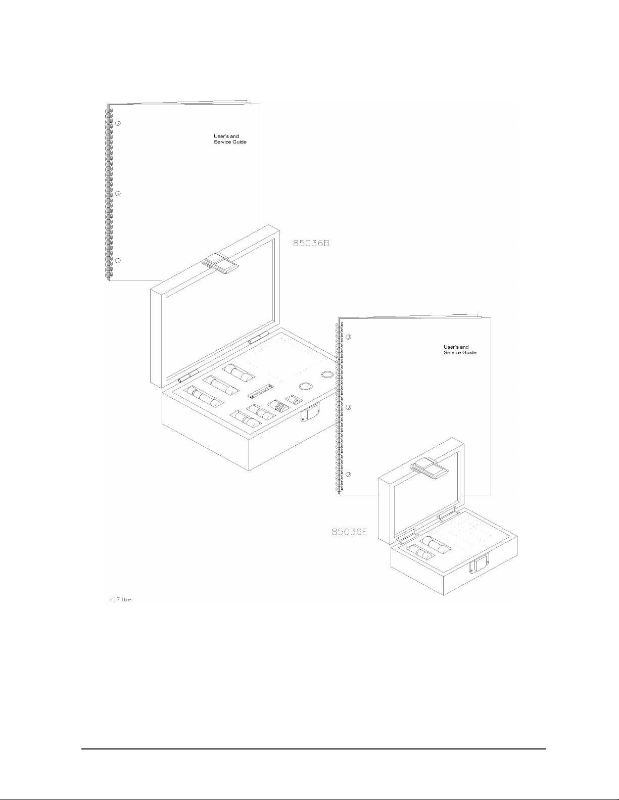
Figure 1-1 Calibration Kit Contents
General Information
Incoming Inspection
85036B/E 1-5
Page 10

General Information
Recording the Device Serial Numbers
Recording the Device Serial Numbers
In addition to the kit serial number, the devices in this kit are individually serialized
(serial numbers are labeled onto the body of each device). Record these serial numbers in
Table 1-1 for the 850 36B and Table 1-2 for the 85036E. Recording the serial numbers will
prevent confusing the devices in this kit with similar devices in other kits.
Table 1-1 Serial Number Reco rd for 85036B
Device Serial Number
Calibration kit
Male broadband load
Female broadband load
Male open
Female open body
Male short
Female short
Type-N male to male adapter
Type-N- female to female adapter
Type-N- male to female adapter
_______________________________
_______________________________
_______________________________
_______________________________
_______________________________
_______________________________
_______________________________
_______________________________
_______________________________
_______________________________
Table 1-2 Serial Number Reco rd for 85036E
Device Serial Number
Calibration kit
Male broadband load
_______________________________
_______________________________
Male combination ope n/sho r t
1-6 85036B/E
_______________________________
Page 11

General Information
Calibration Kits Documented in this Manual
Calibration Kits Documented in this Manual
This manual applies to any 85036B or 85036E calibration kit whose serial prefix is listed
on the title page. If your calibration kit has a different serial number prefix than the one
listed on the title page, refer to “Calibration Kit History” below for information on how this
manual applies.
Calibration Kit History
This section describes calibration kits with serial number prefixes different than those
listed on the title page.
Agilent 8 5036B kits with serial prefix 3102A and below
• 75 ohm load specification: return loss ≥ 45 db, dc to 2 GHz
• all other kit components unspecified
85036B calibration kits with serial number prefix 3102A and below should meet the
specifications published in this manual. If you wish to have your kit recertified to current
specifications, contact your nearest Agilent service center. For contact information, see
Table 5-1 on page 5-3.
Agilent 8 5036B kits with serial prefix 3103A and below
These calibration kits had a center conductor extender with a smaller body. Therefore, a
different procedure was used for connecting the female open. If you’re using one of the
smaller extenders, replace steps 1 through 3 in “Connecting and Disconnecting the
Two-Piece Female Open (85036B) ” on page 3-9 of this manual with the steps below.
1. Mate the center conductor extender to the male pin of the test port.
2. Connect the open body to the test port by carefully guiding it over the extender.
3. To disconnect the open, carefully remove the open body first.
The part numbers in this manual are the recommended replacement parts for these kits
(including the center conductor extender).
85036B/E 1-7
Page 12

General Information
Clarifying the Sex of a Connector
Clarifying the Sex of a Connector
In this manual, the s ex of c a li bra tion de vices a nd ada pt ers ar e r ef erred to in terms of their
connector interface. For example, a male open has a male connector.
However, during a measurement calibration, the network analyzer softkey menus label a
type-N calibration device with reference to the sex of the analyzer’s test port
connector—not the calibration device connector. For example, the label SHORT(F) on the
analyzer’s display refers to the short that is to be connected to the female test port. This
will be a male short from the calibration kit.
Conversely, connector gages are referred to in terms of the connector that it measures. For
instance, a male connector ga ge has a female connector on the gage so that it can measure
male dev ices.
Preventive Maintenance
The best techniques for maintaining the integrity of the devices in this kit include:
• routine visual inspection
• cleaning
• proper gaging
• proper connection techniques
All of the above are described in Chapter 3 , “Use, Maintenance, and Care of the Devices.”
Failure to detect and remove dirt or metallic particles on a mating plane surface can
degrade repeatability and accuracy and can damage any connector mated to it. Improper
connections, resulting from pin depth values being out of the limits (see Table 2-3 on page
2-3), or from bad connections, can also damage these devices.
1-8 85036B/E
Page 13

2 Specifications
2-1
Page 14

Specifications
Environmental Requirements
Environmental Requirements
Table 2-1 Environmental Requirements
Parameter Limits
Operating temperature
Error-corrected temperature range
Storage temperature −40 °C to +75 °C (−40 °F to +167 °F)
Altitude
Operation < 4,500 meters (≈15,000 feet)
Storage < 15,000 meters (≈50,000 feet)
Relative humidity Always non-condensing
Operation 0 to 80% (26 °C maximum dry bu lb)
Storage 0 to 95%
a. The temperatu re rang e over which the calibration standards maintain confor ma nce to their
specification s .
b. The allowable network analy z er ambient temp erature drift during measurement calibration
and during measurem ents when t he ne twor k analyzer er ror co rre cti on is t urne d on. Al so, the
range over which the network an aly z er m aintains its spe cified performance while correction
is turned on.
a
b
+18 °C to +28 °C (+64 °F to +82 °F)
±1 °C of measurement calibration temperature
Temperature—What to W atch Out For
Changes in temperature can affect electrical characteristics. Therefore, the operating
temperature is a critical factor in performance. During a measurement calibration, the
temperature of the calibration devices must be stable and within the range specified in
Table 2-1.
IMPORTANT Avoid unnecessary handling of the devices during calibration because your
fingers are a heat source.
2-2 85036B/E
Page 15
Specifications
Mechanical Specifications
Mechanical Specifications
The mechanical specifications in T able 2-2 apply to the devices in the 85036B and the
85036E 75 Ω type-N calibration kits.
Table 2-2 Mechanical Specifications
Device Specification
Type-N Male Open Inside diameter of outer conductor: 6.9 8 5 to 7.010
Type-N Male Short Inside diameter of outer conductor: 7 ±0.015 mm
Distance from reference plane to shorting plane: 5.29 ±0.013 mm
Supplemental Mechanical Characteristics
Supplemental characteristics are values which are typically met by a majority of the
calibration kit devices tested at Agilent. These supplemental characteristics are intended
to provide information useful in calibration kit applications by giving typical, but
non-warranted performance parameters. Table 2-3 lists the typical characteristics of the
devices in this kit.
Table 2-3 Mechanical Characteristics
Device Characteristic
Type-N Male Short Diameter of male pin: 0.897 ±0.013 mm
All Type-N Male Connectors Pin depth: 0.207 to 0.210 inch
All Type-N Female Connectors Pin depth: 0.204 to 0.207 inch
85036B/E 2-3
Page 16

Specifications
Electrical Specifications
Electrical Specifications
The electrical specifications in Table 2-4 apply to the devices in your calibration kit when
connected with an Agilent precision interface.
Table 2-4 Electrical Specifications
Device Specification Frequen cy (G H z)
a
Loads
a. 23° +5 °C; typical resistance change: ±300 ppm/°C
Return loss ≥ 46 dB (ρ ≤ 0.00501) DC to ≤ 2
Return loss ≥ 40 dB (ρ ≤ 0.01000) > 2 to ≤ 3
Certification
Agilent Technologie s certi f ies that this product m et its published speci fi c ations a t the time
of shipment from the factory. Agilent further certifies that its calibration measurements
are traceable to the United States National Institute of Standards and Technology (NIST)
to the extent allowed by the institute’s calibration facility, and to the calibration facilities
of other International Standards Organization members. See “How Agilent Verifies the
Devices in This Kit” on page 4-2 for more informat io n .
2-4 85036B/E
Page 17

3 Use, Maintenance, and Care of the
Devices
3-1
Page 18

Use, Maintenance, and Care of the Devices
Electrostatic Discharge
Electrostatic Discharge
Protection against ESD (electrostatic discharge) is essential while connecting, inspecting,
or cleaning connectors attached to a static-sensitive circuit (such as those found in test
sets).
Static electricity can build up on your body and can easily damage sensitive internal
circuit elements when discharged. Static discharges too small to be felt can cause
permanent damage. Devices such as calibration components and devices under test
(DUTs), can also carry an electrostatic charge. To prevent damage to the test set,
components, and devices:
• always wear a grounded wrist strap having a 1 MΩ resistor in series with it when
handling components and devices or when making connections to the test set.
• always use a grounded, conductive table mat while making connections.
• always wear a heel strap when working in an area with a conductive floor. If you are
uncertain about the conductivity of your floor, wear a heel strap.
• always ground yourself before you clean, inspect, or make a connection to a
static-sensitive dev ice or tes t port. You can, for example, grasp the gr ounded outer s hel l
of the test port or cable connector briefly.
• always ground the center conductor of a test cable before making a connection to the
analyzer test port or other static-sensitive device. This can be done as follows:
1. Connect a short (from your calibration kit) to one end of the cable to short the center
conductor to the outer conductor.
2. While wearing a grounded wrist strap, grasp the outer shell of the cable connector.
3. Connect the other end of the cable to the test port.
4. Remove the short from the cable.
Refer to Chapter 6 , “Replaceable Parts ,” for part numbers and in st ru ctions for o rdering
ESD protective devices.
Figure 3-1 ESD Protection Setup
3-2 85036B/E
Page 19

Use, Maintenance, and Care of the Devices
Visual Inspection
Visual Inspection
Visual inspection and, if necessary, cleaning should be done every time a connection is
made. Metal particles from the connector threads may fall into the connector when it is
disconnected. One connection made with a dirty or damaged connector can damage both
connectors beyond repair.
In some cases, magnification is necessary to see damage on a connector; a magnifying
device with a magnification of ≥10× is recommended. However, not all defects that are
visible only under magnification wi ll affect the elec trical per formance of the connector. Use
the following guidelines when evaluating the integrity of a connector.
Look for Obvious Defects and Damage First
Examine the connectors first for obvious defects and damage: badly worn plating on the
connector interface, deformed threads, or bent, broken, or misaligned center conductors.
Connector nuts should move smoothly and be free of burrs, loose metal particles, and
rough spots.
What Causes Connector Wear?
Connector wear is caused by connecting and disconnecting the devices. The more use a
connector gets, the faster it wears and degrades. The wear is greatly accelerated when
connectors are not kept clean, or are connected incorrectly.
Connector wear eventually d egra des performance of the dev ice. Calibration d evi ce s sho uld
have a long life if their use is on the order of a few times per week. Replace devices with
worn connectors.
The test port connectors on the network analyzer test s et may have many connections each
day, and are therefore more subject to wear. It is recommended that an adapter be used as
a test port saver to minimize the wear on the test set’s test port connectors.
Inspect the Mating Plane Surfaces
Flat contact between the connectors at a ll point s on their mating plane sur faces is required
for a good connection. Look especially for deep scratches or dents, and for dirt and metal
particles on the connector mating plane surfaces. Also look for signs of damage due to
excessive or uneven wear or misalignment.
Light burnishing of the mating plane surfaces is normal, and is evident as light scratches
or shallow circular marks distributed more or less uniformly over the mating plane
surface. Other small defects and cosmetic imperfections are also normal. None of these
affect electrical or mechanical performance.
If a connector shows deep scratches or dents, particles clinging to the mating plane
surfaces, or uneven wear, clean and inspect it again. Devices with damaged connectors
should be discarded. Determine the cause of damage before connecting a new, undamaged
connector in the same configuration.
85036B/E 3-3
Page 20

Use, Maintenance, and Care of the Devices
Cleaning Connectors
Inspect the Precision Slotless Connectors (female)
Precision slotle ss female connectors are used to improve acc uracy. The slotless contacts are
not affected by the slight variations in male contact pin diameter. However, it is still
advisable to inspect them regularly for damage.
NOTE Inspection is particularly important when mating nonprecision to precision
devices.
Cleaning Connectors
Clean connectors are essential for ensuring the integrity of RF and microwave coaxial
connections.
1. Use Compressed Air or Nitrogen
WARNING Always use protective eyewear when using compressed air or
nitrogen.
Use compressed air (or nitrogen) to loosen particles on the connector mating plane
surfaces.
You can use any source of clean, dry, low-pressure compressed air or nitrogen that has
an effective oil-vapor filter and liquid condensation trap placed just before the outlet
hose.
Ground the hose nozzle to prevent electrostatic discharge, and set the air pressure to
less than 414 kP a (60 ps i) to con trol the vel ocity of th e air stream. High- velocity s treams
of compressed air can cause electrostatic effects when directed into a connector. These
electrostatic effects can damage the device . Refe r to “Electrostatic Discha r ge” earlier in
this chapter for additional information.
2. Clean the Connector Threads
WARNING Keep isopropyl alcohol away from heat, sparks, and flame. Store in a
tightly closed container. It is extremely flammable. In case of fire, u se
alcohol foam, dry chemical, or carbon dioxide; water may be
ineffective.
Use isopropyl alcohol with adequate ventilation and avoid contact
with eyes, skin, and clothing. It causes skin irritation, may cause eye
damage, and is harmful if swallowed or inhaled. It may be harmful if
absorbed through the skin. Wash thoroughly after handling.
In case of spill, soak up with sand or earth. Flush spill area with
water.
Dispose of isopropyl alcohol in accordance with all applicable
federal, state, and local environmental regulations.
3-4 85036B/E
Page 21

Use, Maintenance, and Care of the Devices
Cleaning Connectors
Use a lint-free swab or cleaning cloth moistened with isopropyl alcohol to remove any
dirt or stubborn contaminants on a connector that cannot be removed with compressed
air or nitrogen. Refer to T abl e 6-3 on page 6-5 for part numbers f or isopropy l alcohol and
cleaning swabs.
a. Apply a small amount of isopropyl alcohol to a lint-free cleaning swab.
b. Clean the connector threads.
c. Let the alcohol evaporate, then blow the threads dry with a gentle stream of clean,
low-pressure compressed air or nitrogen. Always completely dry a connector before
you reassemble or use it.
3. Clean the Mat ing Plane Surfaces
a. Apply a small amount of isopropyl alcohol to a lint-free cleaning swab.
b. Clean the center and outer conductor m ating plane sur faces . When clea ning a female
connector, avoid snagging the swab on the center conductor contact fingers by using
short strokes.
c. Let the alcohol evaporate , then blow the connector dry wit h a gentle stream of clean,
low-pressure compressed air or nitrogen. Always completely dry a connector before
you reassemble or use it.
4. Reinspect
Inspect the connector again to make sure that no particles or residue are present.
85036B/E 3-5
Page 22

Use, Maintenance, and Care of the Devices
Connections
Connections
Good connections require a skill ed op erator. The most comm o n caus e of me asu rement error
is bad connections. The following procedures illustrate how to make good connections.
CAUTION Never mate a 50 ohm connector with a 75 ohm connector. The larger center
pin of a male 50 ohm connector will destroy the contact fingers of a female
75 ohm connector.
How to Make a Connection
Preliminary Connection
1. Ground yourself and all devices. Wear a grounded wrist strap and work on a grounded,
conductive table mat. Refer to “Electrostatic Discharge” on page 3-2 for ESD
precautions.
2. Visually inspect the connectors. Refer to “Visual Inspection” on page 3-3.
3. If necessary, clean the connectors. Refer to “Cleaning Connectors” on page 3-4.
4. Carefully align the connectors. The male connector center pin must slip concentrically
into the contact finger of the female connector.
5. Push the connectors straight together.
CAUTION Do not turn the device body. Only turn the connector nut. Damage to the
center conductor can occur if the device body is twisted.
Do not twist or screw the connectors together. As the center conductors mate, there is
usually a slight resistance.
6. The preliminary connection is tight enough when the mating plane surfaces make
uniform, light contact. Do not overtighten this connection.
A connection in which the outer conductors make gentle contact at all points on both
mating surfaces is sufficient. Very light finger pressure is enough to accomplish this.
7. Make sure the connectors are properly supported. Relieve any side pressure on the
connection from long or heavy devices or cables.
Final Connection Using a Torque Wrench
1. Use a torque wrench to make a final connection. Table 3-1 provides information about
the torque wrench recommended for use with this calibration kit. A torque wrench is
not included in the calibration kit. Refer to Chapter 6 for part numbe r an d ordering
inform at ion.
3-6 85036B/E
Page 23

Use, Maintenance, and Care of the Devices
Connections
Table 3-1 Torque Wrench Infor ma tion
Connector Type Torque Setting Torque Tolerance
Type-N 135 N-cm (12 in-lb) ±13.5 N-cm (±1.2 in-lb)
Using a torque wrench guarantees that the connection is not too tight, preventing
possible connector damage. It also guarantees that all connections are equally tight
each time.
2. Prevent the rotation of anything other than the connector nut that you are tightening.
It may be possible to do this by hand if one of the connectors is fixed (as on a test port).
In all situations, however, it is recommended that you use an open-end wrench to keep
the body of the device from turning. Refer to Chapter 6 “Replaceable Parts” for part
number and ordering information.
3. Position both wrenches within 90 degrees of each other before applying force. See
Figure 3-2 . Wrenches opposing each other (greater than 90 degrees apart) will cause a
lifting action which can misalign and stress the connections of the devices involved.
This is especially true when several devices are connected together.
Figure 3-2 Wrench Positions
85036B/E 3-7
Page 24

Use, Maintenance, and Care of the Devices
Connections
4. Hold the torque wrench lightly, at the end of the handle only (beyond the groove). See
Figure 3-3.
Figure 3-3 Using t he Torque Wrench
5. Apply downwa rd fo rce perpendicular t o the wrench handle. See Figu re 3- 3 . This applies
torque to the connection through the wrench.
Do not hold the wrench so tightly that you push the handle straight down along its
length rather than pivoting it, otherwise you apply an unknown amount of torque.
6. Tighten the connection just to the torque wrench break point. The wrench handle gives
way at its internal pivot point. See Figure 3-3. D o not tighten the connection further.
CAUTION You don’t have to fully break the handle of the torque wrench to reach the
specified torque; doing so can cause the handle to kick back and loosen the
connection. Any give at all in the handle is sufficient torque.
Do not pivot the wrench handle on your thumb or other fingers , other wis e you apply an
unknown amount of torque to the connection when the wrench reaches its break point.
Do not twist the head of the wrenc h r el ative to the outer conductor mating pla ne. If you
do, you apply more than the recommended torque.
3-8 85036B/E
Page 25

Use, Maintenance, and Care of the Devices
Connections
Connecting and Disconnecting the Two-Piece Female Open (85036B)
The female open standard in the 85036B calibr ation kit is composed of two parts: the open
body (outer conductor) and the center conductor extender. Refer to Figure 3 -4 .
Figure 3-4 Connecting the Two-Piece Female Open
To connect the female open:
1. Connect the open body to the male test port.
2. Insert the center conductor extender into the hole at the end of the body and push
gently until the center conductors mate.
To disconnect the female open:
1. Remove the center conductor extender by pulling gently outwards without twisting,
rocking, or bending the extender or the body.
2. Disconnect the body from the test port.
How to Separate a Connection
To a void l ateral (bending) f orce on the connecto r mating plane surf aces, alw ays support the
devices and connections.
CAUTION Turn the connector nut, not the device body. Major damage to the center
conductor can occur if the device body is twisted.
1. Use an open-end wrench to prevent the device body from turning.
2. Use another open-end wrench to loosen the connector nut.
3. Complete the separation by hand, turning only the connector nut.
4. Pull the connectors straight apart without twisting, rocking, or bending either of the
connectors.
85036B/E 3-9
Page 26

Use, Maintenance, and Care of the Devices
Handling and Storage
Handling and Storage
• Install the protective end caps and store the calibration devices in the foam-lined
storage case when not in use.
• Never store connectors loose in a box, desk, or bench drawer. This is the most common
cause of connector damage during storage.
• Keep connectors clean.
• Do not touch mating plane surfaces. Natural skin oils and microscopic particles of dirt
are easily transferred to a connector interface and are very difficult to remove.
• Do not set connectors contact-end down on a hard surface. The plating and the mating
plane surfaces can be damaged if the interface comes in contact with any hard surface.
3-10 85036B/E
Page 27

4 Performance Verification
4-1
Page 28

Performance Verification
Introduction
Introduction
The performance of your calibra tion kit can only be verified b y retur ning the kit to Agi len t
Technologies for recertification. The equipment required to verify the specifications of the
devices in the kit has been specially manufactured and is not commercially available.
How Agilent Verifies the Devices in This Kit
Agilent verifies the specifications of these devices as follows:
1. The residual microwave error terms of the test system are verified with precision
airlines and shorts that are directly traced to NIST (National Institute of Standards
and Technology). Th e airline and sh o rt characterist ics are develo pe d fro m mechan ical
measurements. The mechanical measurements and material properties are carefully
modeled to give very accurate electrical representa tion. The mechanical measurements
are then traced to NIST through various plug and ring gages and other mechanical
measurements.
2. Each calibration device is electrically tested on this system. For the initial (before sale)
testing of the ca li brat ion de vi ces , Agilent includes the test measurement uncer tai nty a s
a guardband to guarantee each device meets the published specification. For
recertifications (after sale), no guardband is used and the measured data is compared
directly with the specification to determine the pass or fail status. The measurement
uncertainty for each device is, however, recorded in the calibration report that
accompanies recertified k it s.
These two steps establish a traceable link to NIST for Agilent to the extent allowed by the
institute’s calibration facility. The specifications data provided for the devices in this kit is
traceable to NIST through Agilent Technologies.
4-2 85036B/E
Page 29

Perf ormance Verification
Recertification
Recertification
The following will be provided with a recertified kit:
• a new calibration sticker affixed to the case
• a certificate of calibrati on
• a calibration report for each device in the kit listing measured values, specifications,
and uncertainties
NOTE A list of NIST traceable numbers may be purchased upon request to be
included in the calibration report.
Agilent Technologies offers a Standard calibration for the recertification of this kit. For
more information, contact Agilent Technologies. See Table 5 -1 o n page 5-3.
Limited Recertification
The 75Ω loads in the calibration kit are specified for use up to 3 GHz. For many
applications, the performance above 2 GHz is not utilized.
For a standard recertification, the devices in the calibration kit are tested and calibrated
up to 3 GHz. However, a limited recertification can be requested. For this limited
recertification, the devices are tested and calibrated up to 2 GHz.
To reques t a limited recer tificati on, make sure the following is clearly written on the order:
Limited Calibration DC–2 GHz.
All loads that receive a limited calibration are supplied with a limited calibration label
applied to the device.
How Often to Recertify
The suggested initial inter val fo r recertifi cation i s 12 months or sooner. The actual need for
recertification depends on the use of the kit. After reviewing the results of the initial
recertification, you may establi sh a different recertif ication inter val that reflects the usage
and wear of the kit.
NOTE The recertification interva l should begin on the date the kit is first used after
the recertification date.
Where to Send a Kit for Recertification
Contact Agilent Technologies for information on where to send your kit for recertification.
See Table 5-1 on pa ge 5-3.
When you return the kit, complete and attach a service tag. Refer to “Returning a Kit or
Device to Agilent” on page 5-3 for details.
85036B/E 4-3
Page 30

Performance Verification
Recertification
4-4 85036B/E
Page 31

5 Troubleshooting
5-1
Page 32

Troubleshooting
T roubleshooting Process
Troubleshooting Process
If you suspect a bad calibration, or if your network analyzer does not pass performance
verification, follow the steps in Figure 5-1.
Figure 5-1 Troubleshooting Flowchart
5-2 85036B/E
Page 33

Troubleshooting
Returning a Kit or Device to Agilent
Returning a K it or Device to Agilent
If your kit or device requir es service , conta ct the Agile nt T ec hnologies offi ce nearest yo u for
information on where to send it. See Table 5-1. Include a service tag (located near the end
of this manual) on which you provide the following information:
• your company name and address
• a technical contact person within your company, and the person's complete phone
number
• the model number and serial number of the kit
• the part number and serial number of each device
• the type of service required
•a detailed description of the problem and how the device was being used when the
problem occurred (such as calibration or measurement)
Table 5-1 Contacting Agilent
Online assistance: www.agilent.com/find/assist
United States
(tel) 1 800 452 4844
New Zealand
(tel) 0 800 738 378
(fax) (+64) 4 495 8950
Malaysia
(tel) 1 800 828 848
(fax) 1 800 801 664
Taiwan
(tel) 0800-047-866
(fax) (886) 2 25456723
Latin America
(tel) (305) 269 7500
(fax) (305) 269 7599
Japan
(tel) (+81) 426 56 7832
(fax) (+81) 426 56 7840
Philippines
(tel) (632) 8426802
(tel) (PLDT subscriber
only):
1 800 16510170
(fax) (632) 8426809
(fax) (PLDT subscriber
only):
1 800 16510288
People’s Republic of
China
(tel) (preferred ):
800-810-0189
(tel) (alternate):
10800-650-0021
(fax) 10800-650-0121
Canada
(tel) 1 877 894 4414
(fax) (905) 282-6495
Australia
(tel) 1 800 629 485
(fax) (+6 1) 3 9210 5947
Thailand
(tel) outside Bangk ok :
(088) 226 008
(tel) with in Bangko k :
(662) 661 3999
(fax) (66) 1 661 3714
India
(tel) 1-600-11-2929
(fax) 000-800-650-1101
Europe
(tel) (+31) 20 547 2323
(fax) (+31) 20 547 2390
Singapore
(tel) 1 800 375 8100
(fax) (65) 836 0252
Hong Kong
(tel) 800 930 871
(fax) (852) 2506 9233
85036B/E 5-3
Page 34

Troubleshooting
Returning a Kit or Device to Agilent
5-4 85036B/E
Page 35

6 Replaceable Parts
6-1
Page 36

Replaceable Parts
Introduction
Introduction
Table 6-1 lists the replacement part numbers for items included in the 85036B calibration
kit and Figure 6-1 illustrates each of these items.
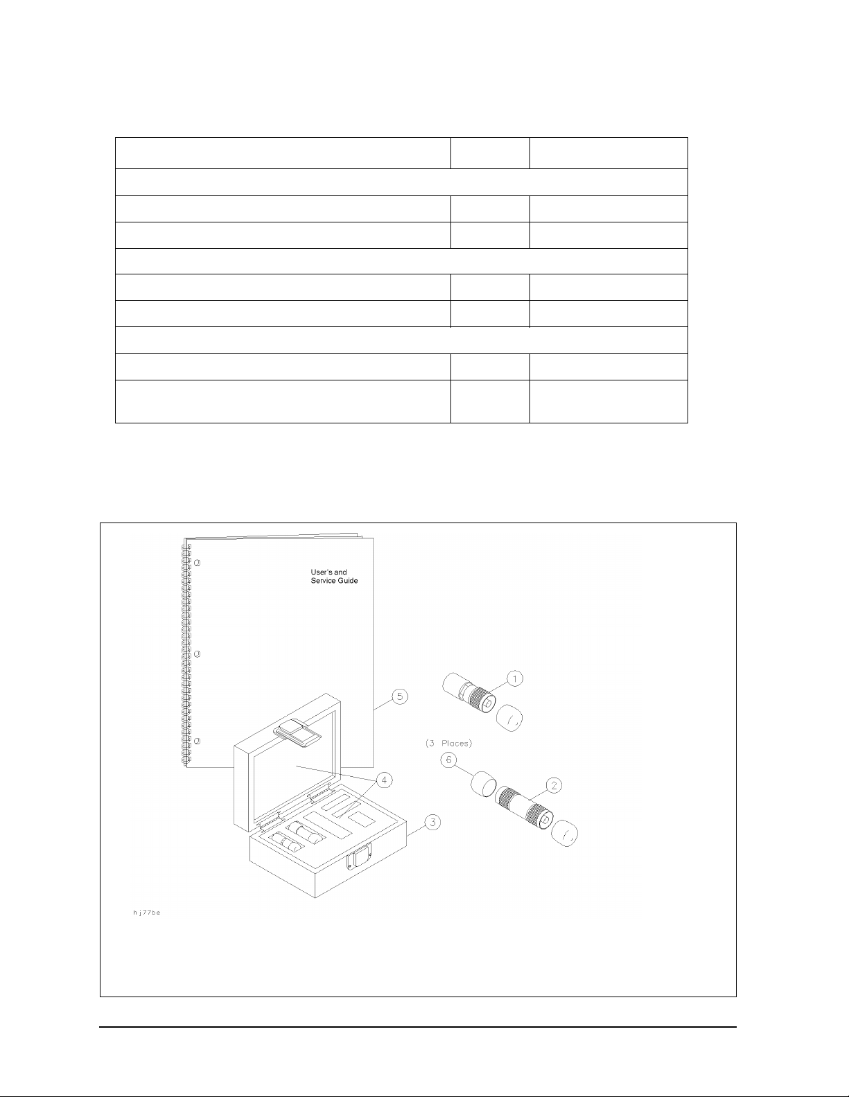
Table 6-2 lists the replacement part numbers for items included in the 85036E calibration
kit and Figure 6-2 illustrates each of these items.
Table 6-3 lists the replacement part numbers for items recommended or required for
successful operation but not included in the calibration kit.
To order a listed part, note the description, the part number, and the quantity desired.
Telephone or send your order to Agilent Technologies. See Table 5-1 on page 5-3.
Table 6-1 Replaceab le Parts for the 85036B Calibration Kit
Descripti on Qty Per Kit Agilent Part Number
Calibration Devices (75Ω Type-N)
Male broadband load 1 00909-60019
Fe male broadband load 1 00909-60020
Male short 1 85036-60012
Fe male short 1 85036-60011
Male open 1 85032-60007
Fe male open body 1 85032-20001
Female open center conductor extender
Adapters
Type-N-male to male 1 85036-60013
Type-N-female to female 1 85036-60014
Type-N-male to female 1 85036-60015
Calibration Kit Storage Case
Box 1 85036-80001
Foam pad set
Miscellaneous Item s
User’s and s erv ice guide 1 85036-90016
Male protectiv e end caps as required 1401-0214
1 85036-60019
1
85036-80002
Female protective end caps as required 1401-0225
Tube package (for center conductor extender) 1 1540-1027
6-2 85036B/E
Page 37

Figure 6-1 Replacea ble Parts for the 85036B Calibration Kit
Replaceable Parts
Introduction
85036B/E 6-3
Page 38
Replaceable Parts
Introduction
Table 6-2 Replaceable Parts for the 85036E Calibration Kit
Descript ion Qty Per Kit Agilent Part Number
Calibration Devices (75Ω Type-N)
Male broadband load 1 00909-60019
Male combination open/short 1 85036-60016
Calibration Kit Storage Case
Box 1 9211-1582
Foam pad set 1 85023-80005
Miscellaneous Items
User’s and service guide 1 85036-90016
Male protective end cap
as
required
1401-0214
Figure 6-2 Replaceable Parts for the 85036E Calibration Kit
6-4 85036B/E
Page 39

Replaceable Parts
Introduction
Table 6-3 Replaceable Parts—Items Not Included in the 85036B and 85036E
Calibration Kits
Description Qty Agilent Part Number
Connector Gages (75Ω Type-N)
Connector gage set 1 85036B K01
Wrenches
3/4 in, 135 N-cm (12 in-lb) torque wrench 1 8710-1766
1/2 in and 9/16 in open-end wrench 1 8710-1770
3/4 in open-end wrench 1 8720-0011
ESD Protective Devices
Grounding wrist strap 1 9300-1367
5 ft grounding cord for wrist strap 1 9300-0980
2 ft by 4 ft conductive table mat with 15 ft grounding wire 1 9300-0797
ESD heel strap 1 9300-1308
Connector Cleaning Supplies
Isopropyl alcohol 30 ml 8500-5344
Foam tip ped cleaning swabs 100 9301-1243
Miscellaneous Items
Connector car e - quick reference card 1 08510-90360
85036B/E 6-5
Page 40

Replaceable Parts
Introduction
6-6 85036B/E
Page 41

A Standard Definitions
A-1
Page 42

Standard Definitions
Standard Class Assignments
Standard C l ass Assignments
Class assignment organizes calibration standards into a format compatible with the error
models used in the measu rement c alibration. A class or group of classe s corr espo nds t o the
systematic errors to be removed from the measured network analyzer response. T able A-1
lists the classes of the devices in this calibration kit.
Table A-1 Standard Class Assignments
Calibration Kit Label: N 75 Ω
Class A B C D E F G Standard Class Label
A2
S
11
S
B17 Shorts
11
S
C3 Load
11
S
A28 Opens
22
S
B17 Shorts
22
S
C3 Load
22
Forward Transmi ssi o n 4 Thru
Reverse Transmission 4 Thru
Forward Match 4 Thru
Reverse Mat ch 4 Thru
Response 1 7 2 8 4 Response
Response and Isolation 1 7 2 8 4 Response & Isolation
8
Opens
A-2 85036B/E
Page 43

Standard Definitions
Standard Class Assignments
Blank Form
The standard class assignments listed in Table A-1 may be changed to meet your specific
requirements. Table A-2 is provided to record the modified standard class assignments.
Table A-2 Standard Class Assignments Blank Form
Calibration Kit Label: ______________
Class A B C D E F G Standard Class
Label
S
A
11
S
B
11
S
C
11
S
A
22
S
B
22
S
C
22
Forward Transmissio n
Reverse Transmission
Forward Match
Reverse Match
Response
Response and Isolation
85036B/E A-3
Page 44

Standard Definitions
Nominal Standard Definitions
Nominal Standard Definitions
Standard definitions provide the constants needed to mathematically model the electrical
characteristics (delay, attenuation, and impedance) of each calibration standard. The
nominal values of these constants are theoretically derived from the physical dimensions
and material of each cali bration standard , or from actua l measured response. These values
are used to determine the measurement uncertainties of the network analyzer. The
standard definitions in Table A-3 list typica l c ali brat ion ki t p arameter s used to sp ec ify the
mathematical model of each device. This information must be loaded into the network
analyzer to perform valid calibrations. Refer to your network analyzer’s user’s guide for
instructions on loading calibration constants.
NOTE The values in the standard definitions table are valid only over the specified
operating temperature range.
Setting the System Impedance
This kit contains only 75 ohm devices. Ensure the system impedance (Z0) is set to 75 ohms.
Refer to your network a na ly zer’s user’s guide for i ns tr uctions on setting system im pedance .
A-4 85036B/E
Page 45

Table A-3 Standard Definitions
Standard Definitions
Nominal Standard Definitions
System Z
Standard
1
2
3
4
5
6
7
8
a
= 75 Ω
0
b
F
15
−
Number
Type
Short
Open
Load Fixed
Delay/
Thru
Short
Open
C0 ×10
63.5 84 56 0 0 75 1.1
e
41
F/Hz
27
−
C1 ×10
40 5 0 17.544 75 1.1
2
F/Hz
36
−
C2 ×10
Calibration Kit Label: N 75 Ω
c
3
F/Hz
45
−
C3 ×10
Fixed or Sliding
17.544 75 1.1
Offset Freq
(GHz)
Ω
0
Delay (ps)
0751.13G0999
0751.13G0999
0751.13G0999
Loss (Ω/s)
Z
3G
3G
3G
Min
Max
0999
0999
0999
d
Coax or Waveguide
Coax
Coax
Coax Broad-
Coax Thru
Coax
Coax
Standard Label
Short (m)
Open (m)
band
Short (f)
Open (f)
d
d
d
d
a. Ensure system impedance (Z0) of network analyzer is set to this value.
b. Open, short, load, delay/thru, or arbitrary impedance.
c. Load or arbitrary impedance only.
d. Standard labels that specify sex, (m) or (f), refer to the sex of the analyzer’s test port connector.
e. If your instrument is an Agilent 8752B or 8711 Option 1EC, and you are calibrating at the test port, this number is 33. For all
other instruments and applications, including calibrating at a point other than the test port (such as the end of a cable), 41 is
the correct number. This is because the 8752B and 8711 Option 1EC have special female test ports with longer, more rugged
fingers.
85036B/E A-5
Page 46

Standard Definitions
Nominal Standard Definitions
Blank Form
The standard definitions listed in Table A-3 may be changed to meet your specific
requirements. Table A-4 is provided to record the modified standard definitions.
Table A-4 Standard Definitions Blank Form
System Z
Standard
Number
1
2
3
4
5
6
7
8
a
= ______________
0
b
F
15
−
Type
C0 ×10
Calibrati on K it Label:
____________________
Offset Freq
2
F/Hz
F/Hz
27
36
−
−
C1 ×10
C2 ×10
c
3
F/Hz
45
−
Ω
C3 ×10
Fixed or Sliding
Delay (ps)
0
Z
Loss (GΩ/s)
(GHz)
Min
Max
d
Coax or Waveguide
Standard Label
a. Ensu r e syst e m Z
of network analyzer is set to this value .
0
b. Open, short, load, delay/ thru, or arbitrary im ped ance.
c. Lo ad or arbitrary impedanc e only.
d. Standard labels that specify sex, (m) or (f), refer to the sex of the analyzer’s test port connector.
A-6 85036B/E
Page 47

Index
A
adapters
part numbers, 6-5
alcohol
isopropyl
altitude, 2-2
B
blank form
standard cla ss assignments
standard definitions, A-6
broadband loads, 1-2
C
cal kit
contents
overview, 1-2
return to Agilent, 5-3
serial number, 1-6
calibration
bad
certificate of, 4-2
constants, 1-3
limited, 4-3
standards, 2-4
temperature, 2-2
calibrat io n constants
entering, 1-3
permanently stored, 1-3
calibration definitions, 1-3
calibration kit
conte nt s, 1-2
overview, 1-2
return to Agilent, 5-3
serial number, 1-6
calibration kit history, 1-7
calibration label
part number
calibration rep o rt, 4-2
calibration sticker, 4-3
certificate of calibration, 4-2
certification
specifications
class assignment
standard
class assignments
blank form
cleaning co nnecto rs, 3-4
cleaning sup p lie s, 1-3
ordering, 6-5
part numbers, 6-5
compressed air or nitrogen, 3-4
connecting the two-piece female open, 3-9
connections, 3-2, 3-6, 3-9
cautions in making, 3-6
disconnecting, 3-9
ESD concerns, 3-6
final, 3-6
, 1-3
as cleaning solvent
, 3-4
, 1-2
, 5-2
permanently stored, 1-3
, 6-5
, 2-4
, A-2
, A-3
, A-3
how to ma ke, 3-6
preliminary, 3-6
two-piece female open, 3-9
undoing, 3-9
using a torque wrench, 3-6
connector
cleaning
cleaning supp lie s, 6-5
damage, 3-3
female, 3-4
life, 3-3
mating plane, 3-5
precisio n slotle ss (f e ma le), 3-4
sex, 1-8
threads, 3-4
visual inspection, 3-3
wear, 3-3
constants
calibration, 1-3
entering, 1-3
permanently stored, 1-3
contacting Agilent Technologies, 5-3
contents
kit, 1-2
D
damage
shipment
to connectors, 3-3
damaged connectors, 3-3
data, recertific ation, 4-2
defect iv e co nnectors, 3-3
definitions
standard, A-4
device
connecting
disconnecting, 3-9
handling, 3-10
maintenance, 1-8
part numbers, 6-5
return to Agilent, 5-3
storage, 3-10
temperature, 2-2
visual inspection, 3-3
device s
how Agilent verifies
serial numbers, 1-6
disconnecting the two-piece female open, 3-9
disconnection
two-piece female open
disconnections, 3-9
distance from ref plane to shorting plane,
docume ntation warranty, ii
E
electrical specific atio ns
electrostatic dis ch arg e, 3-2
supplies
part numbers
, 3-4
, 1-4
, 3-6
, 4-2
, 3-9
specifications, 2-3
, 2-4
, 6-5
85036B/E
Index-1
Page 48

Index
when making connections
environmental requirements, 2-2
equipment
required
but not supplied, 1-3, 6-2, 6-5
supplied, 1-2, 6-2, 6-4
ESD, 3-2
precautions, 3-2, 3-4
supplies
part numbers
when making connections, 3-6
F
female open
connecting, 3-9
disconnecting, 3-9
frequency
specifications
freq uency range, 2-4, 4-3
G
gage
connector
master
gage master
part numbers
gages, 1-3
H
handling
histor y, calib ration kit , 1-7
humidity, 2-2
I
impedance
system
incoming inspection, 1-4
inside diamet er of outer conductor, specifications, 2- 3
inspection
damage, 3-3
defects, 3-3
incoming, 1-4
mating plane, 3-3
visual, 3-3
isopropyl alcohol
as cleaning solvent
K
kit
contents
overview, 1-2
return to Agilent, 5-3
serial number, 1-6
L
label
calibration
part number, 6-5
, 1-3
, 6-5
, 3-9
, 2-4
, 6-5
, 6-5
, 3-10
, A-4
, 3-4
, 1-2
, 4-3
, 3-6
limited calibra t ion, 4-3
limited calibration
requesting, 4-3
loads
broadband
M
maintenance
preventive, 1-8
maintenance of devices, 1-8
making connections, 3-6
manual
part number, 6-5
mating plane
connector
mating plane inspection, 3-3
mating plane surfaces, 3-5
mechanical specificatio n s , 2-3
N
nitrogen
nominal standard definitions, A-4
numbers
serial
recording, 1-6
O
offices
sales and service
open-end wrench, 1-3, 3-9
part number, 6-5
opens, 1-2
opens and shorts, 1-2
ordering parts, 6-2
P
part numbers
parts
ordering
replaceable, 6-2
required but not supplied, 6-2
performance verification, 4-2
fail, 5-2
permanently stored calibration definitions, 1-3
pin depth
typical values
precision slotless connec to rs, 3-4
preventive maintenance, 1-8
R
recertificatio n
how often?, 4-3
interval, 4-3
limited, 4-3
what’s included, 4-3
where to se nd yo ur kit, 4-3
regulatio ns
environmental
replaceable parts, 6-2
, 1-2
, 3-2
, 3-5
, 3-4
, 1-6
, 5-3
, 6-2
, 6-2
, 2-3
, 4-3
, 3-5
Index-2
85036B/E
Page 49

Index
requirements
environmental
return loss
specifications
return, kit or device, 5-3
S
sales
and service offices
sales and service of fice s, 5-3
serial numbers, 1-6
devices, 1-6
recording, 1-6
service, 5-2
and sales offices, 5-3
service tag , 1-4, 4-3, 5-3
sex
connector
shipment
damage
verifying complete, 1-4
shorts, 1-2
specifications, 2-2
altitude, 2-2
certification, 2-4
distance from ref plane to shorting plane, 2-3
electrical, 2-4
environmental, 2-2
frequency, 2-4
humidity, 2-2
inside diameter of outer conductor , 2-3
mechanical, 2-3
return loss, 2-4
temperature, 2-2
verifying, 4-2
standard clas s assignment s, A-2
blank form, A-3
standard definitions, A-4, A-6
blank form, A-6
nominal, A-4
standards
calibration
NIST, 2-4, 4-3
static discha rg e , 3-2
sticker
calibration
storage, 3-10
altitude, 2-2
humidity , 2-2
temperature , 2-2
supplies
cleaning
system impedance
setting, A-4
, 1-4
, 2-2
, 2-4
, 5-3
, 1-8
, 2-4
, 4-3
, 1-3
device, 2-2
error-corrected temperature range, 2-2
measurement, 2-2
operating range, 2-2
verification and measurement, 2-2
test data, 4-2
thre ads
connect or, 3-4
torque wrench, 1-3, 3-6
part number, 6-5
specificatio ns, 3-6
traceability, 4-2
troubleshooting, 5-2
two-piece female open, 3-9
V
verification
performance
temperature, 2-2
visual inspection, 3-3
W
warranty, documentation
wrench
open-end, 1-3, 3-9
part number, 6-5
undoing connections , 3-9
torque, 1-3
part number, 6-5
wrenches
part numbers, 6-5
, 4-2
, ii
T
tag
service
temperature
calibration
85036B/E
, 1-4, 4-3, 5-3
, 2-2
Index-3
 Loading...