

Page 1

DX-D 300
DX
-D
300
DX
-D 300
DX
-D 300
8207/050
User Manual
0172B EN 20160512 1056
Page 2

| DX-D 300 | Contents
2
Contents
Legal Notice ..........................................................................4
Introduction to this Manual ................................................... 5
Scope .........................................................................6
Warnings, Cautions, Instructions and Notes ...............7
Disclaimer ................................................................. 8
Introduction .......................................................................... 9
Intended Use ............................................................10
Intended User .......................................................... 11
Configuration .......................................................... 12
Operation Controls .................................................. 14
NX Application on the NX Workstation .........15
Software Console on the NX Workstation ..... 16
DR Detector Switch on the NX Workstation ....
17
X-Ray generator control in the operator room ..
19
U-arm control panel .....................................20
Control panel of the collimator .....................21
DR Detector handle control buttons ............. 22
U-arm remote control .................................. 23
DR Detector ................................................. 24
Emergency stop button ................................ 25
Emergency shutdown power switch ............. 26
System Documentation ............................................ 27
The DX-D 300 User Documentation ..............28
The Getting Started material ........................28
Options and Accessories ...........................................29
Anti-scatter grids ......................................... 29
Product Complaints ................................................. 30
Compliance ..............................................................31
General ........................................................32
Safety .......................................................... 32
Electromagnetic Compatibility .....................32
X-Ray Safety ................................................ 32
Classification ............................................... 33
Connectivity ............................................................ 34
X-ray Exposure Parameters .......................... 34
Labels ...................................................................... 35
Type label .................................................... 35
Messages ................................................................. 36
Installation .............................................................. 37
Cleaning and Disinfecting ........................................ 38
Cleaning ...................................................... 39
Disinfecting ................................................. 40
Approved disinfectants .................................41
0172B EN 20160512 1056
Page 3

DX-D 300 | Contents | 3
Patient data security ................................................ 42
Maintenance ............................................................43
Environmental protection ........................................ 44
Safety Directions ......................................................45
Operation ............................................................................ 48
Starting DX-D 300 ....................................................49
Basic workflow using the DR Detector ......................50
Step 1: retrieve the patient info .................... 51
Step 2: Select the exposure .......................... 52
Step 3: Prepare the exposure ........................53
Step 4: Check the exposure settings ............. 54
Step 5: execute the exposure ........................55
Step 6: perform a quality control ..................56
Workflow for Full Leg Full Spine examination ..........57
Basic workflow using a CR cassette .......................... 58
Step 1: retrieve the patient info ....................59
Step 2: select the exposure ...........................60
Step 3: Prepare the exposure ........................61
Step 4: Check the exposure settings ............. 62
Step 5: Execute the exposure ....................... 63
Step 6: repeat steps 2 to 5 for the next
subexposures ............................................... 64
Step 7: digitize the image ............................. 65
Step 8: perform a quality control ..................66
Stopping the System ................................................ 67
Problem solving ................................................................... 68
DR Detector is Exceeding the Maximum Working
Temperature ............................................................ 69
DR Detector must be Recalibrated ............................69
DR Detector Problem ............................................... 69
Technical Data .....................................................................71
DX-D 300 Technical Data ......................................... 72
Fixed DR Detector Technical Data ............................ 73
U-Arm Technical Data ..............................................75
Portable DR Detector Technical Data ........................76
0172B EN 20160512 1056
Page 4

4 | DX-D 300 | Legal Notice
Legal Notice
0413
Agfa HealthCare NV, Septestraat 27, B-2640 Mortsel - Belgium
For more information on Agfa products and Agfa HealthCare products, please
visit www.agfa.com.
Agfa and the Agfa rhombus are trademarks of Agfa-Gevaert N.V., Belgium or
its affiliates. NX and DX-D 300 are trademarks of Agfa HealthCare N.V.,
Belgium or one of its affiliates. All other trademarks are held by their
respective owners and are used in an editorial fashion with no intention of
infringement.
Agfa HealthCare N.V. makes no warranties or representation, expressed or
implied, with respect to the accuracy, completeness or usefulness of the
information contained in this document and specifically disclaims warranties
of suitability for any particular purpose. Products and services may not be
available for your local area. Please contact your local sales representative for
availability information. Agfa HealthCare N.V. diligently strives to provide as
accurate information as possible, but shall not be responsible for any
typographical error. Agfa HealthCare N.V. shall under no circumstances be
liable for any damage arising from the use or inability to use any information,
apparatus, method or process disclosed in this document. Agfa HealthCare
N.V. reserves the right to make changes to this document without prior notice.
The original version of this document is in English.
Copyright 2016 Agfa HealthCare N.V
All rights reserved.
Published by Agfa HealthCare N.V.
B-2640 Mortsel - Belgium.
No part of this document may be reproduced, copied, adapted or transmitted
in any form or by any means without the written permission of Agfa
HealthCare N.V.
0172B EN 20160512 1056
Page 5

DX-D 300 | Introduction to this Manual | 5
Introduction to this Manual
Topics:
• Scope
• Warnings, Cautions, Instructions and Notes
• Disclaimer
0172B EN 20160512 1056
Page 6

6 | DX-D 300 | Introduction to this Manual
Scope
This User Manual describes the features of the DX-D 300 System, an
integrated Digital Radiography X-Ray System to be used as medical diagnostic
aid in General Radiography and emergency departments. It explains how the
different components of the DX-D 300 System work together.
0172B EN 20160512 1056
Page 7
DX-D 300 | Introduction to this Manual | 7
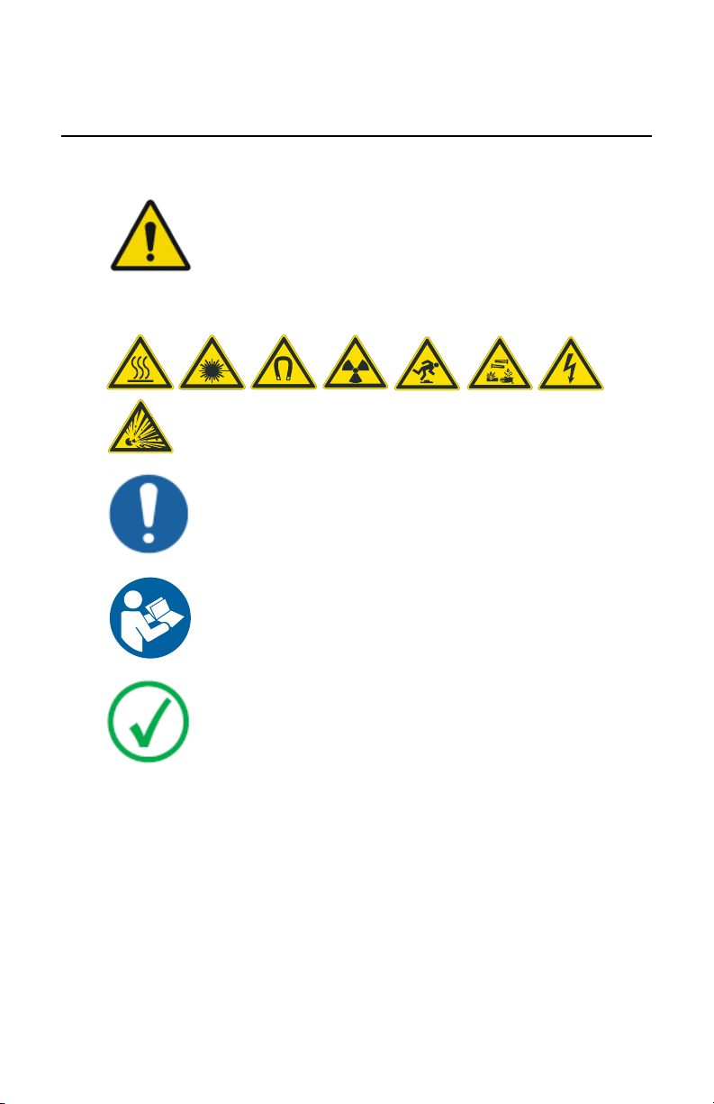
Warnings, Cautions, Instructions and Notes
The following samples illustrate how warnings, cautions, instructions and
notes appear in the user documentation. The text explains their intended use.
Warning: Warnings are directions which, if they are not
followed, can cause fatal or serious injuries to a user,
engineer, patient or any other person or can lead to a
mistreatment.
The purpose of safety icons is to indicate at a glance the type of caution,
warning or danger.
Caution: Cautions are directions which, if they are not followed,
can cause damage to the equipment described in this manual or
any other equipment or goods and can cause environmental
pollution.
Instruction: This sign is typically used in combination with the
warning sign when providing a specific instruction. If it is followed
exactly, it should avoid the subject of the warning.
Note: Notes provide advice and highlight unusual points. A note is
not intended as an instruction.
0172B EN 20160512 1056
Page 8

8 | DX-D 300 | Introduction to this Manual
Disclaimer
Agfa assumes no liability for use of this document if any unauthorized
changes to the content or format have been made.
Every care has been taken to ensure the accuracy of the information in this
document. However, Agfa assumes no responsibility or liability for errors,
inaccuracies or omissions that may appear in this document. To improve
reliability, function or design Agfa reserves the right to change the product
without further notice. This manual is provided without warranty of any kind,
implied or expressed, including, but not limited to, the implied warranties of
merchantability and fitness for a particular purpose.
Note: In the United States, Federal law restricts this device to sale
by or on the order of a physician.
0172B EN 20160512 1056
Page 9

Introduction
Topics:
• Intended Use
• Intended User
• Configuration
• Operation Controls
• System Documentation
• Options and Accessories
• Product Complaints
• Compliance
• Connectivity
• Labels
• Messages
• Installation
• Cleaning and Disinfecting
• Patient data security
• Maintenance
• Environmental protection
• Safety Directions
DX-D 300 | Introduction | 9
0172B EN 20160512 1056
Page 10

10 | DX-D 300 | Introduction
Intended Use
The DX-D 300 system is an integrated X-ray imaging system used in hospitals,
clinics and medical practices by physicists, radiographers and radiologists to
make, process and view static X-ray radiographic images of the skeleton
(including skull, spinal column and extremities), chest, abdomen and other
body parts on adult, pediatric or neonatal patients.
Applications can be performed with the patient in the sitting, standing or
lying position.
This device is not intended for mammography applications.
0172B EN 20160512 1056
Page 11

DX-D 300 | Introduction | 11
Intended User
This manual has been written for trained users of Agfa products and trained
diagnostic X–Ray clinical personnel who have received proper training.
Users are those persons who actually handle the equipment and those who
have authority over the equipment.
Before attempting to work with this equipment, the user must read,
understand, note and strictly observe all warnings, cautions and safety
markings on the equipment.
0172B EN 20160512 1056
Page 12
DX
-D
300
DX
-D 300
DX
-D 300
1
2
3
4
5
6
7
8
| DX-D 300 | Introduction
12
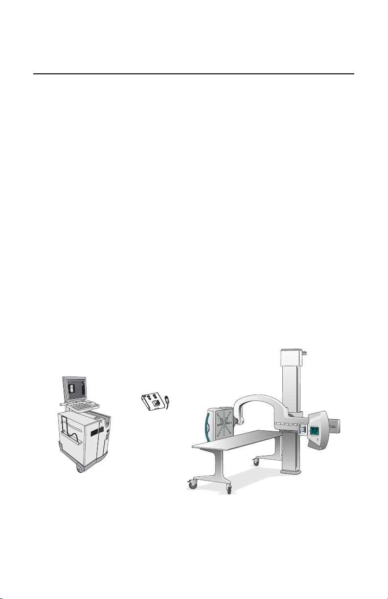
Configuration
DX-D 300 is a DR X-ray system (Direct Radiography X-ray system) that can be
combined with components from a CR X-ray system.
The complete DX-D 300 consists of the following components:
• Vertical column with U-arm
• X-Ray tube with automatic collimator with DAP (dose area product meter)
• Integrated 4343R DR Detector or DR Detector Bucky
• Portable DR Detector
• Mobile table
• X-Ray generator
• NX workstation
The use of the DR Detector bucky is restricted to DR Detectors with a size
equivalent to 14x17 inch (43x35 cm) and 43x35 CR Cassettes.
The DX-D 300 configuration with integrated DR Detector automatically
detects the grid status. The DX-D 300 configuration with DR Detector Bucky
does not detect the grid status.
DX-D 300 can be used in combination with:
• CR digitizer
DX-D 300 supports the Full Leg Full Spine application with integrated 4343R
DR Detector or with a DR Detector with a size equivalent to 14x17 inch (43x35
cm) in the DR bucky.
NX workstation
1.
2.
3.
4.
5.
In-room CR Digitizer
X-Ray Generator Control
Mobile table
DR Detector
0172B EN 20160512 1056
Page 13

DX-D 300 | Introduction | 13
U-arm
6.
Vertical column
7.
X-Ray tube
8.
Figure 1: DX-D 300 configuration with integrated DR Detector
0172B EN 20160512 1056
Page 14
DX
-D
300
DX
-D 300
DX
-D 300
1 2 3 4 5
14 | DX-D 300 | Introduction
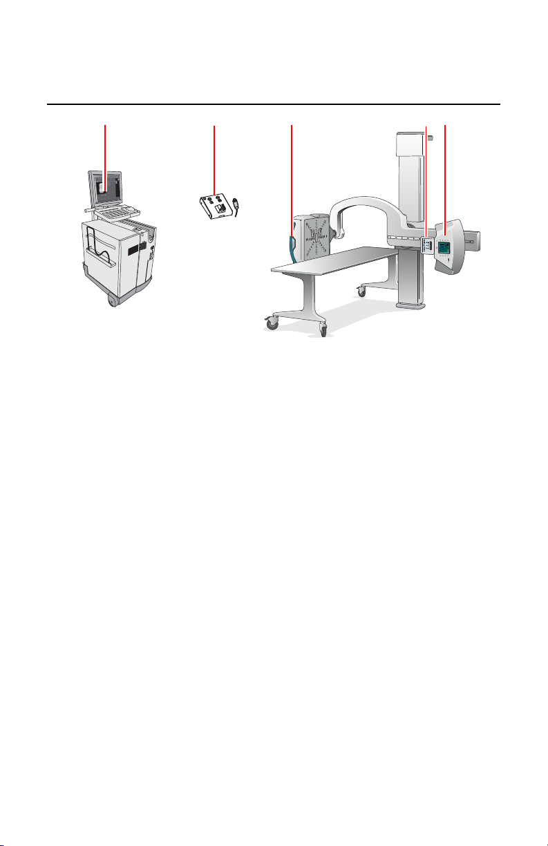
Operation Controls
NX application and software console
1.
X-Ray generator control box
2.
DR Detector handle control buttons
3.
Collimator control panel
4.
U-arm control panel
5.
Figure 2: DX-D 300 operation controls
Topics:
• NX Application on the NX Workstation
• Software Console on the NX Workstation
• DR Detector Switch on the NX Workstation
• X-Ray generator control in the operator room
• U-arm control panel
• Control panel of the collimator
• DR Detector handle control buttons
• U-arm remote control
• DR Detector
• Emergency stop button
• Emergency shutdown power switch
0172B EN 20160512 1056
Page 15
DX-D 300 | Introduction | 15
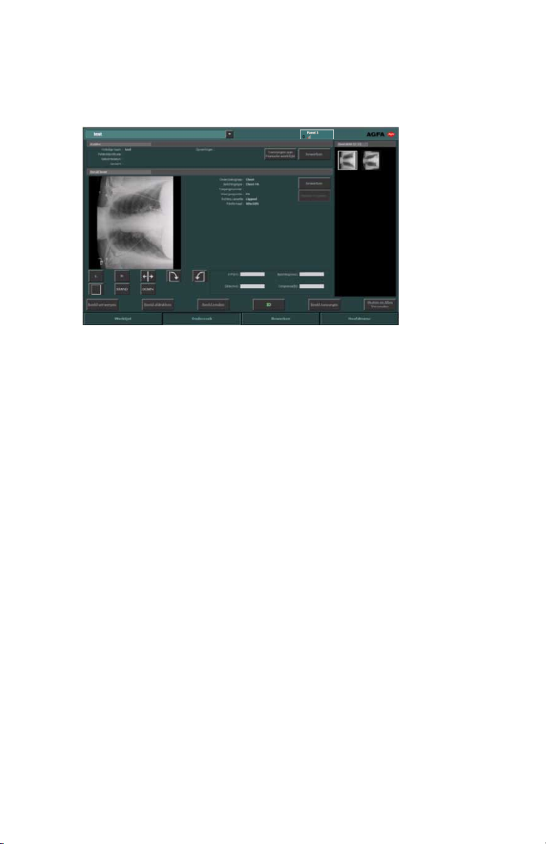
NX Application on the NX Workstation
The NX application is used to define patient information, select exposures and
process images.
Figure 3: the NX application
0172B EN 20160512 1056
Page 16
16 | DX-D 300 | Introduction
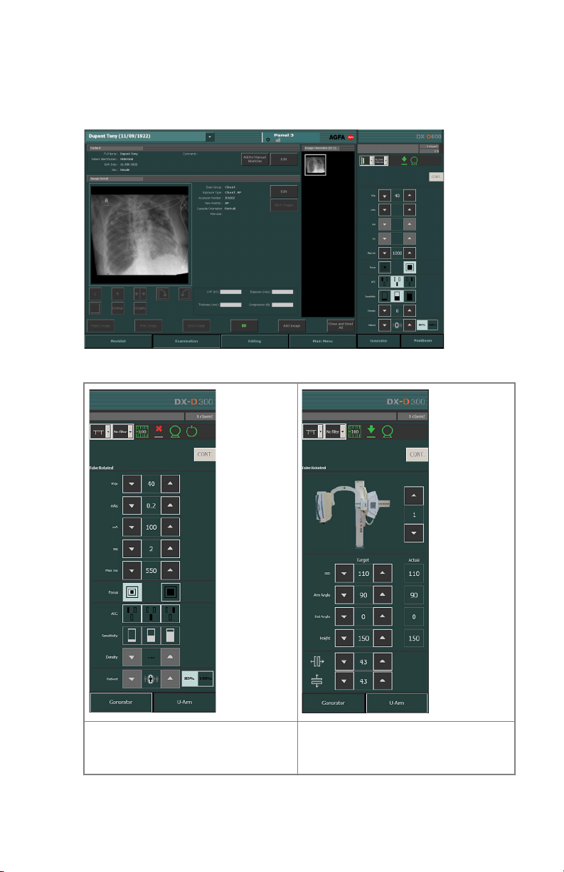
Software Console on the NX Workstation
The Software Console is used to control X-Ray generator settings and X-Ray
system position.
The software console has two screens:
Figure 4: X-Ray generator controls Figure 5: X-Ray system automatic
0172B EN 20160512 1056
positioning controls
Page 17
DX-D 300 | Introduction | 17
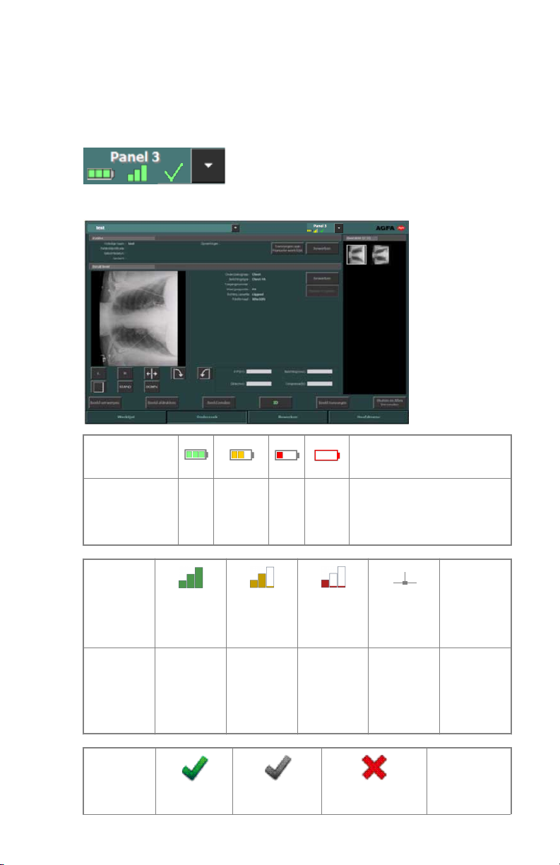
DR Detector Switch on the NX Workstation
The DR Detector Switch is available in the title bar of the NX application. The
DR Detector Switch shows which DR Detector is active and shows its status.
The DR Detector Switch can be used to activate another DR Detector.
It is positioned in the title bar of the NX application.
Battery status
icon
Meaning Full Medium Low Empty Wired DR Detector
Wireless DR Detector is off
Connectio
n status
icon
(wifi/
wired)
Meaning Good Low Bad Wired DR
DR
Detector
status icon
(blinking)
(empty)
or disconnected
Detector
0172B EN 20160512 1056
(empty)
DR
Detector is
off or
disconnect
ed
(empty)
Page 18

18 | DX-D 300 | Introduction
Meaning DR Detector
is ready for
exposure
DR Detector is
initializing for
exposure
DR Detector is
off or
disconnected or
in error
DR Detector
is inactive
(no
thumbnail
selected)
0172B EN 20160512 1056
Page 19
DX-D 300 | Introduction | 19
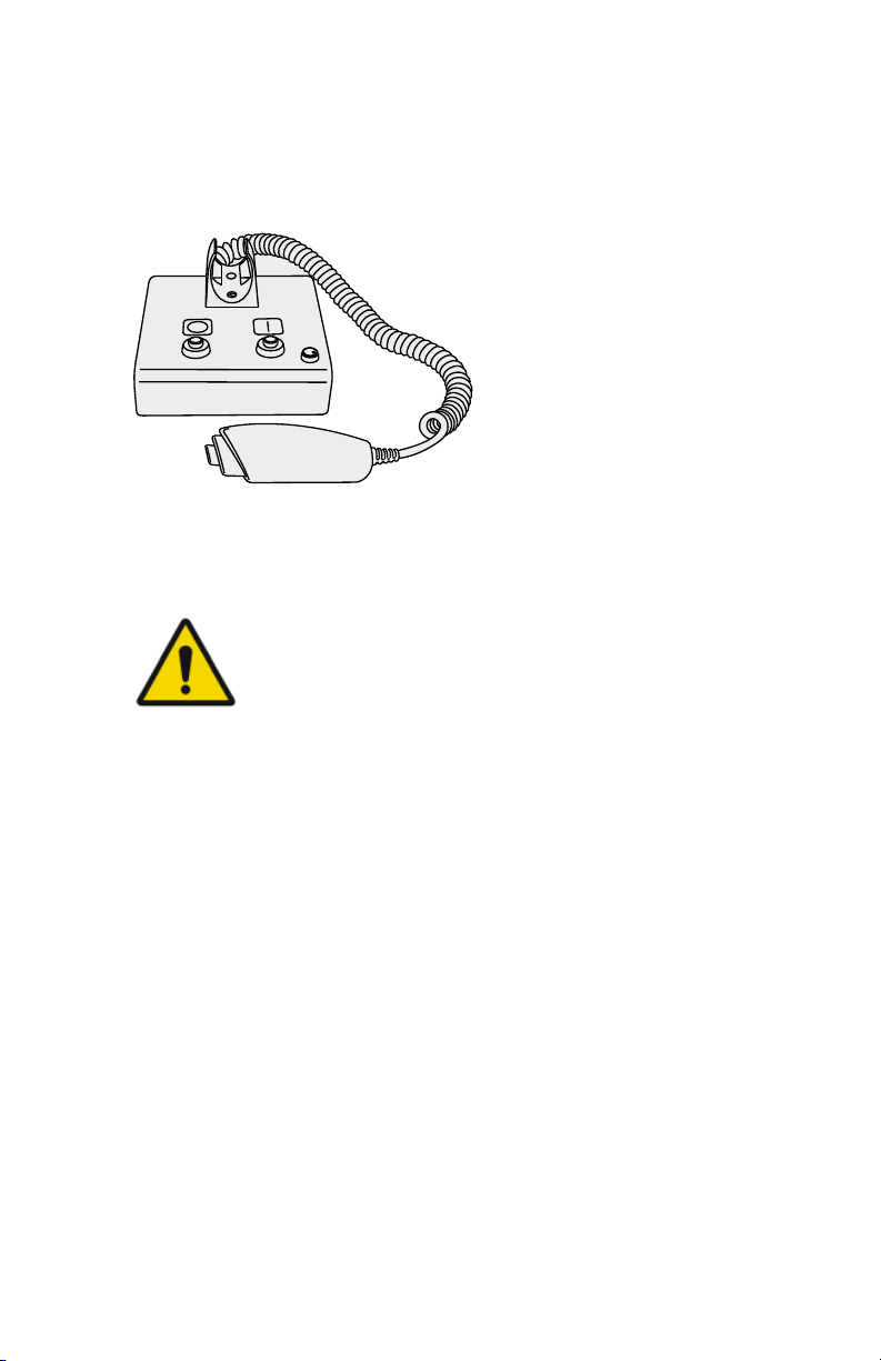
X-Ray generator control in the operator room
The X-Ray generator control box contains buttons to switch on and off the XRay generator and a handswitch to make exposures.
Figure 6: the X-Ray generator control box
Following warning is printed on the X-ray generator control box in English:
Warning: This x-ray unit may be dangerous to patient and
operator unless safe exposure factors, operating
instructions and maintenance schedules are observed.
0172B EN 20160512 1056
Page 20
MOVE
SID
DX-D 300
20 | DX-D 300 | Introduction
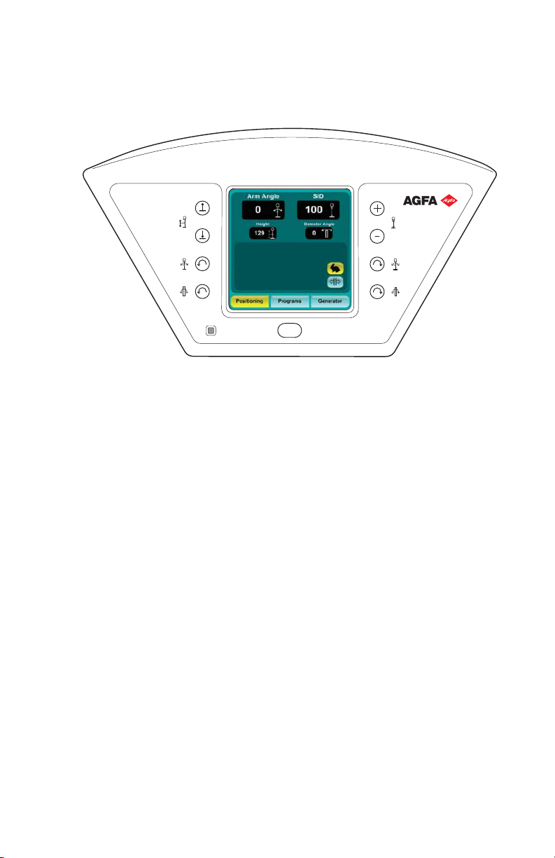
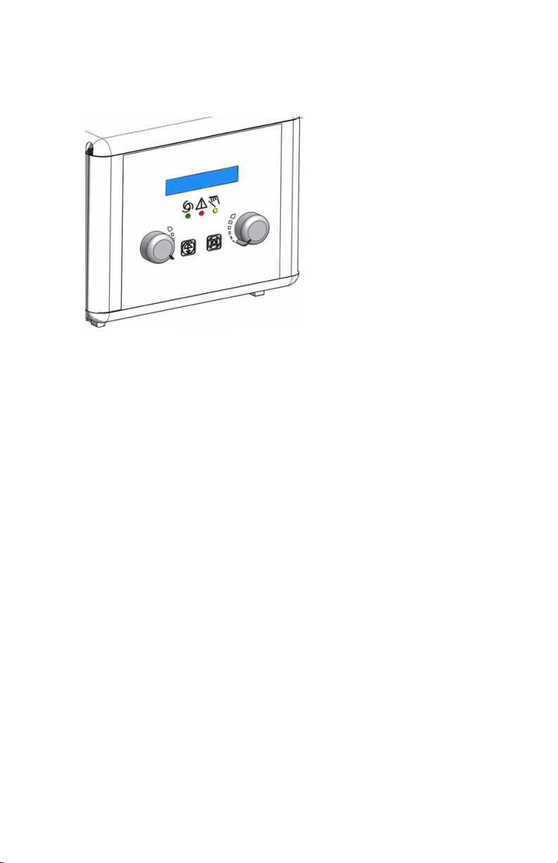
U-arm control panel
On the U-arm.the control panel with touch screen console and control buttons
to control X-Ray generator settings and U-arm position.
Figure 7: U-arm control panel
0172B EN 20160512 1056
Page 21
DX-D 300 | Introduction | 21
Control panel of the collimator
The control panel of the automatic collimator:
Figure 8: the control panel of the automatic collimator
The display shows the dimensions of the collimated area and of the source
image distance (SID) in centimeters or in inches. Values in centimeter have no
decimal point. Values in inches have one digit after the decimal point.
0172B EN 20160512 1056
Page 22

SID
22 | DX-D 300 | Introduction
DR Detector handle control buttons
The DR Detector handle control buttons to control the U-arm position
Figure 9: DR Detector handle control buttons
0172B EN 20160512 1056
Page 23
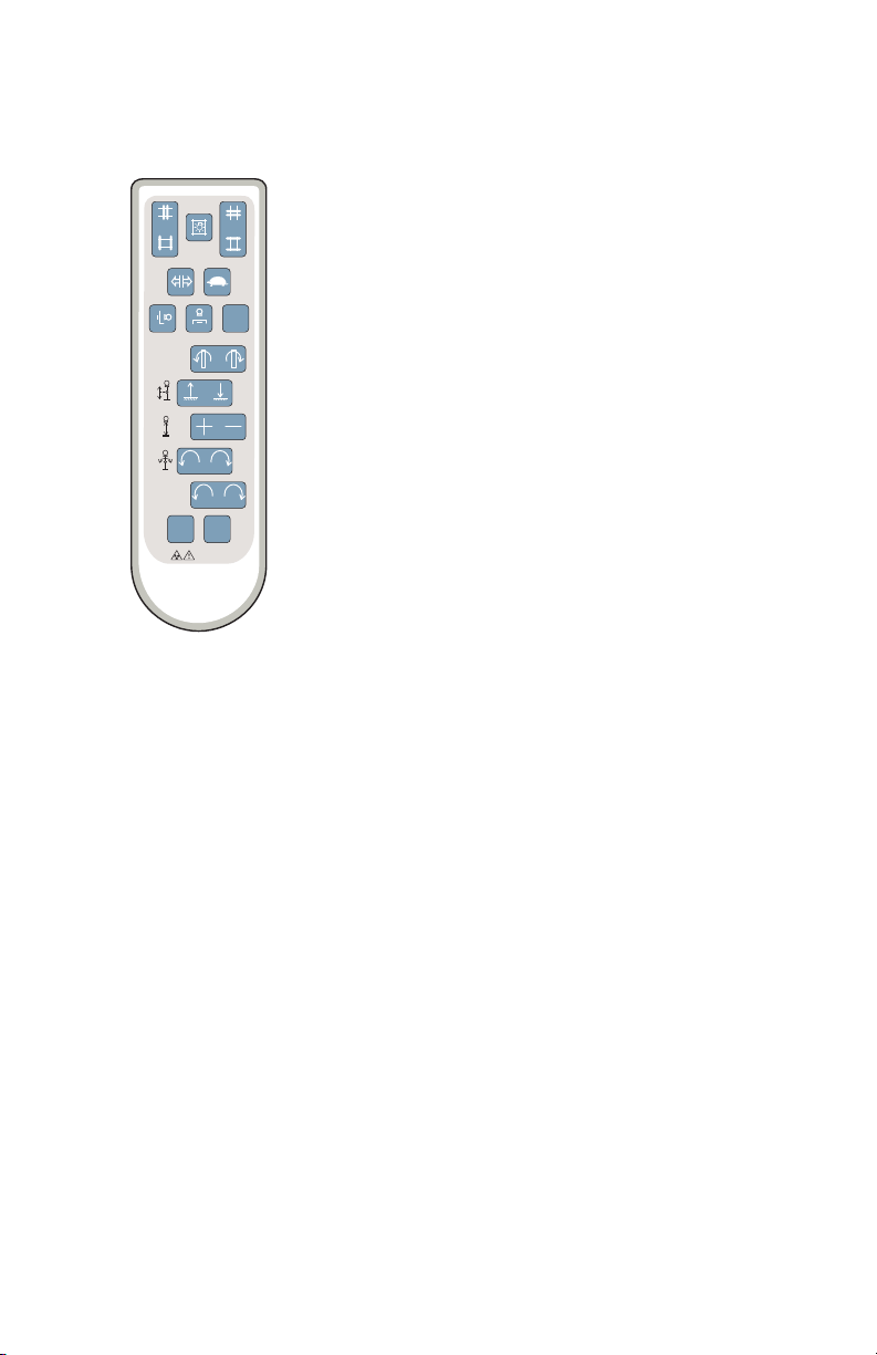
U-arm remote control
SID
TUBE
RO
TATION
DETECTOR
ROTATION
MOVE
F1 F2
The remote control to control U-arm position
Figure 10: U-arm remote control
DX-D 300 | Introduction | 23
0172B EN 20160512 1056
Page 24

24 | DX-D 300 | Introduction
DR Detector
When performing an exposure, keep in mind the following detector
orientation aids:
1. Tube side
2. Patient orientation marker
For an overview of the operation controls of the DR Detector, refer to the user
manual of the DR Detector.
The DR Detector may come in contact with the patient.
Note: DR Detectors that operate wireless contain an RF
transmitter. For detailed information, refer to the DR Detector
User Manual.
0172B EN 20160512 1056
Page 25

DX-D 300 | Introduction | 25
Emergency stop button
Figure 11: Emergency stop button
If a system malfunction causes an emergency situation involving the patient,
operating personnel or any system component, activate the emergency stop.
All motor driven system movements will be stopped.
For detailed information about the emergency button/switch, refer to the DXD 300 U-arm User Manual (document 0171).
0172B EN 20160512 1056
Page 26

26 | DX-D 300 | Introduction
Emergency shutdown power switch
Use the emergency shutdown power switch, if a dangerous situation cannot be
eliminated by pressing the emergency stop button.
Warning: Use the emergency shutdown power switch in case
of danger to patients, operators, third parties, or one of the
units. The entire system will be shut down and the power
supply will be disconnected.
The emergency shutdown power switch for the room is typically located on
the wall and easy to access, often close to the power off switch of the X-ray
system. It is installed and labeled by customer.
Warning: It must be ensured that the emergency switches
are always freely accessible.
0172B EN 20160512 1056
Page 27

DX-D 300 | Introduction | 27
System Documentation
The documentation shall be kept with the system for easy reference. The most
extensive configuration is described within this manual, including the
maximum number of options and accessories. Not every function, option or
accessory described may have been purchased or licensed on a particular
piece of equipment.
Technical documentation is available in the product service documentation
which is available from your local support organization.
The user documentation consists of:
• DX-D 300 User Documentation CD (digital media).
• NX User Documentation CD (digital media).
• Digitizer User Documentation CD (digital media).
• DX-D 300 Owner’s Manual (paper binder).
• Getting Started material.
Topics:
• The DX-D 300 User Documentation
• The Getting Started material
0172B EN 20160512 1056
Page 28

28 | DX-D 300 | Introduction
The DX-D 300 User Documentation
• DX-D 300 User Manual (this document), document 0172.
• DX-D 300 U-arm User Manual, document 0171.
• DX-D Software Console User Manual, document 0189.
• DX-D Full Leg Full Spine User Manual, document 0179.
• User manuals for the supported DR Detectors.
• DX-D DR Detector Calibration Key User Manual, document 0134.
The Getting Started material
• Getting Started with NX, document 4417.
• Getting started with DX-D 300, document 0170.
0172B EN 20160512 1056
Page 29

DX-D 300 | Introduction | 29
Options and Accessories
• DX Full Leg Full Spine Stand (for the DX-D Full Leg Full Spine application)
• CR FLFS Cassette Holder (for the CR Full Leg Full Spine application)
For options and accessories information, refer to the DX-D 300 U-arm User
Manual, document 0171.
Anti-scatter grids
Anti-scatter grids are used to reduce scattered radiation and improve image
quality. Grids are available as an option.
Refer to the Agfa website for specifications on the anti-scatter grids that have
been found compatible with the system and the DR Detectors.
http://www.agfahealthcare.com/global/en/library/overview.jsp?ID=54332498
0172B EN 20160512 1056
Page 30

30 | DX-D 300 | Introduction
Product Complaints
Any health care professional (for example a customer or a user) who has any
complaints or has experienced any dissatisfaction with the quality, durability,
reliability, safety, effectiveness, or performance of this product must notify
Agfa.
If the device malfunctions and may have caused or contributed to a serious
injury, Agfa must be notified immediately by telephone, fax or written
correspondence to the following address:
Agfa Service Support - local support addresses and phone numbers are listed
on www.agfa.com
Agfa - Septestraat 27, 2640 Mortsel, Belgium
Agfa - Fax +32 3 444 7094
0172B EN 20160512 1056
Page 31

Compliance
Topics:
• General
• Safety
• Electromagnetic Compatibility
• X-Ray Safety
• Classification
DX-D 300 | Introduction | 31
0172B EN 20160512 1056
Page 32

32 | DX-D 300 | Introduction
General
• The product has been designed in accordance with the MEDDEV
Guidelines relating to the application of Medical Devices and have been
tested as part of the conformity assessment procedures required by
93/42/EEC Medical Device Directive (European Council Directive
93/42/EEC on Medical Devices).
Safety
• IEC 60601-1: 2005
Electromagnetic Compatibility
• IEC 60601-1-2:2007
X-Ray Safety
• IEC 60601-1-3:2008
• IEC 60601-2-54:2009
• IEC 60601-2-7:1998
For USA
The system conforms to DHHS radiation Standards of 21CFR subchapter J as
of the date of manufacture.
0172B EN 20160512 1056
Page 33

Classification
DX-D 300 | Introduction | 33
Type of protection against electric
shock
Degree of protection against electric
shock
Degree of protection against ingress
of liquids
Methods of disinfection
recommended by the manufacturer
Degree of safety of application in the
presence of flammable anesthetic
mixture with air or with oxygen or
with nitrous oxide
Mode of operation Suitable for continuous operation
Labelling
Class 1 Equipment
Type B Applied Parts
IPX0 as defined in IEC60529.
Ordinary equipment (enclosed
equipment without protection
against ingress of liquids).
Disinfectable equipment (or
elements)
Equipment for use in environments
where no flammable gases or vapors
are present
• CE label: 93/42 EEC 'Medical
Devices' (Europe), EN 60601-1
• CUL label: CSA 22.2 No 601.1
(Canada)
Remarks for HF-emission and
immunity
This equipment generates, uses and
can radiate radio frequency (RF)
energy and, if not installed and used
in accordance with the instructions,
may cause harmful interference to
other devices in the vicinity. In any
circumstance; however, there is no
guarantee that interference will not
occur in a particular installation.
0172B EN 20160512 1056
Page 34

34 | DX-D 300 | Introduction
Connectivity
The NX workstation is connected to the X-ray system to exchange X-ray
exposure parameters.
The NX workstation requires a 100 Mbit ethernet network to exchange
information with a number of other devices.
The NX workstation communicates with other devices in the hospital network
using one of the following protocols:
• DICOM
• IHE
The NX workstation can be connected to a RIS system (input scheduling), a
PACS system (output image/data management) and to a hardcopy device
(output image).
Note: The connections between the components of the system are
separate from the hospital network and should not be disconnected
or modified.
X-ray Exposure Parameters
The X-Ray Exposure Parameters and DAP value can be configured to be
• displayed in the NX Image Detail pane,
• printed in the film text box,
• transmitted to the Archive,
• transmitted to the RIS via MPPS (Modality Performed Procedure Step).
The NX Image Detail pane displays the X-Ray Exposure Parameters and DAP
value for the individual sub-exposures.
Only the cumulative DAP value is transmitted to the Archive.
0172B EN 20160512 1056
Warning: Incomplete exposure parameters (kV, mAs) are
transmitted to Archive for multiple sub-exposures on one
cassette. Only the exposure parameters for one subexposure are transmitted. Don't use multiple sub-exposures
when the exposure parameters are interpreted by the
Archive.
Page 35

Labels
Lable Meaning
DX-D 300 | Introduction | 35
This mark shows compliance of the equipment with Directive
93/42/EEC (for European Union).
This mark indicates that this is a Type B Equipment
Serial number
Manufacturer
Date of manufacture
Dangerous voltage
Ionizing radiation
Type label
Mark Meaning
(Sample of subtype 8207/050)
The type label is located near to the top of
the vertical column.
The type label information for each
combination of X-ray tube and X-ray
generator is available in the technical data.
The 21 CFR Subchapter J label is positioned
close to the type label.
0172B EN 20160512 1056
Page 36

36 | DX-D 300 | Introduction
Messages
Messages are displayed on the NX workstation monitor, on the touch screen
console in the operator room or on the control panel.
Special messages are displayed in a dialog box in the middle of the screen or in
a fixed part of the screen. This message will tell that either a problem has
occurred or that a requested action cannot be performed.
The user must read these messages carefully. They will provide information on
what to do from then on. This will be either performing an action to resolve
the problem or to contact the Agfa service organization.
Details on the contents of messages can be found in the service
documentation which is available to Agfa service personnel.
0172B EN 20160512 1056
Page 37

DX-D 300 | Introduction | 37
Installation
The NX Workstation complies with the UL 60950 / EN 60950 standard for
Information Technology. This means that, although it is absolutely safe,
patients may not come into direct contact with the equipment. Therefore, the
workstation must be placed outside a radius of 1.5 m (EN) or 1.83 m (UL/
CSA) around the patient (according to the local valid regulation).
The other components of the DX-D 300 are suitable for use within the patient
environment.
Caution: Install the NX workstation and CR digitizer at a
minimum (safe) distance of 2 m from the X-Ray System
components or provide a wall or window to separate both
systems.
0172B EN 20160512 1056
Page 38

38 | DX-D 300 | Introduction
Cleaning and Disinfecting
All appropriate policies and procedures should be followed to avoid
contamination of the staff, patients and equipment. All existing universal
precautions should be extended to avoid potential contaminations and to
avoid patients coming into (close) contact with the device. The user is
responsible for selecting a disinfection procedure.
Topics:
• Cleaning
• Disinfecting
• Approved disinfectants
0172B EN 20160512 1056
Page 39

DX-D 300 | Introduction | 39
Cleaning
To clean the exterior of the equipment:
1. Stop the system.
Warning: Wet cleaning of the equipment while it is
connected to the electric circuit includes the risk of
electric shock and of short circuit.
2. Wipe the exterior of the device with a clean, soft, damp cloth. Use a mild
soap or detergent if required. Do not use any corrosive, dissolving or
abrasive cleaning or polishing agents. Make sure no liquid gets in the
device.
Caution: Clean the equipment with only a little moisture.
Caution: Using unsuitable cleaning agents or methods can
damage the property when surface becomes dull and brittle
(e.g. alcohol-containing agents).
Note: Do not open the equipment for cleaning. No components
inside the device require cleaning by the user.
3. Start up the system.
0172B EN 20160512 1056
Page 40

40 | DX-D 300 | Introduction
Disinfecting
To disinfect the device, use only disinfectants and disinfection methods that
are approved by Agfa and that correspond to the national regulation and
guidelines as well as explosion protection. If you plan to use other
disinfectants, approval of Agfa is needed before use, as most disinfectants can
damage the device. UV disinfection is also not allowed.
Perform the procedure following the instructions for use, the disposal
instructions and the safety instructions of the selected disinfectants and tools
and of the hospital.
0172B EN 20160512 1056
Page 41

DX-D 300 | Introduction | 41
Approved disinfectants
Refer to the Agfa website for specifications on the disinfectants that have been
found compatible with the cover material of the device and can be used on the
outer surface of the device.
http://www.agfahealthcare.com/global/en/library/overview.jsp?ID=41651138
0172B EN 20160512 1056
Page 42

42 | DX-D 300 | Introduction
Patient data security
The user must ensure that the patients’ legal requirements are met and that
the security of the patient data is guarded.
The user must define who can access patient data in which situations.
The user must have a strategy available on what to do with patient data in
case of a disaster.
0172B EN 20160512 1056
Page 43

DX-D 300 | Introduction | 43
Maintenance
Maintenance procedures are described in the DX-D 300 Owner’s Manual.
0172B EN 20160512 1056
Page 44

44 | DX-D 300 | Introduction
Environmental protection
Figure 12: WEEE symbol
Figure 13: Battery symbol
WEEE end user notice
The directive on Waste Electrical and Electronic Equipment (WEEE) aims to
prevent the generation of electric and electronic waste and to promote the
reuse, recycling and other forms of recovery. It therefore requires the
collection of WEEE, recovery and reuse or recycling.
Due to the implementation into national law, specific requirements can be
different within the European Member States. The WEEE symbol on the
products, and/or accompanying documents means that used electrical and
electronic products should not be treated as, or mixed with general household
waste For more detailed information about take-back and recycling of this
product please contact your local service organization and/or dealer. By
ensuring this product is disposed of correctly, you will help prevent potential
negative consequences for the environment and human health, which could
otherwise be caused by inappropriate waste handling of this product. The
recycling of materials will help to conserve natural resources.
Battery notice
The battery symbol on the products, and/or accompanying documents means
that the used batteries should not be treated as, or mixed with general
household waste. The battery symbol on batteries or its packaging may be
used in combination with a chemical symbol. In cases where a chemical
symbol is available it indicates the presence of respective chemical substances.
If your equipment or replaced spare parts contain batteries or accumulators
please dispose of them separately according to local regulations.
For battery replacements please contact your local sales organization.
0172B EN 20160512 1056
Page 45

Safety Directions
Warning: Only qualified and authorized personnel shall
operate this system. In this context ‘qualified’ means those
persons legally permitted to operate this equipment in the
jurisdiction in which the equipment is being used, and
‘authorized’ means those persons authorized by the
authority controlling the use of the equipment. Full use
must be made of all radiation protection features, devices,
systems, procedures and accessories.
Warning: Improper changes, additions, maintenance or
repair of the system can lead to personal injury, electrical
shock and damage to the equipment. Safety is only
guaranteed when changes, additions, maintenance or
repairs are carried out by an Agfa certified field service
engineer. A non certified engineer performing a
modification or service intervention on a medical device,
acts on his own responsibility and makes the warranty void.
Warning: Do not connect the equipment with anything
other than specified. Doing so may result in fire or electric
shock.
DX-D 300 | Introduction | 45
Warning: Do not connect additional extensions cords or
multiple power socket outlets to the system.
Warning: Strictly observe all warnings, cautions, notes and
safety markings within this document and on the product.
Warning: Safety is only guaranteed when an Agfa certified
field service engineer has installed the product.
Warning: All Agfa medical products must be used by trained
and qualified personnel.
Warning: Ionizing radiation can lead to radiation injuries if
handled incorrectly. When radiation is applied, the required
protective measures must be complied with.
0172B EN 20160512 1056
Page 46

46 | DX-D 300 | Introduction
Warning: The operator and end-user must take precautions
to protect themselves against dangerous X-ray exposure
when using the DR Detector or CR cassette in the X-ray
beam path of an X-ray source.
Warning: The DR Detector or CR cassette are not intended
to be used as a primary barrier to X-rays. The user is
responsible for ensuring the safety of the operator,
bystanders, and the subjects being radiographed.
Warning: Avoid unnecessary dose by checking before
exposure if the DR Detector Switch displays the name of the
DR Detector that is being used and if the status of the DR
Detector is ready for exposure.
Warning: There is a risk of collision or crushing for patients,
operating staff, unit and objects, caused by unit movements
which could be released by inadmissible actuation of
operating elements by patients.
Warning: System unavailability due to hardware or software
failure. If the product is used in critical clinical workflows, a
backup system has to be foreseen.
Caution: Before moving the U-arm out of horizontal position,
check that no objects are lying on the bucky that can fall off.
0172B EN 20160512 1056
Caution: Damaged grid. Reduced image quality. Please handle
the grids with special care.
Caution: When inserting the scattered radiation grids, it is
essential that the grid corresponds to the intended sourceimage-distance (SID) to which the grid is focussed. Because of
the focussing of the grids, the tube unit must be centered onto
the bucky.
Caution: Excessive ambient temperature may impact
performance of DR Detectors and cause permanent damage to
the equipment. If ambient temperature and humidity is outside
the range of 10 - 35 °C and 30 - 75% RH, do not operate the
system or use air conditioning. Warranty will be void if it is
obvious that operating conditions are not met.
Page 47

DX-D 300 | Introduction | 47
Caution: Power failure can cause an image being lost.
Connect the workstation and the digitizer to an uninterrupted
power supply (UPS) or an institutional standby generator.
0172B EN 20160512 1056
Page 48

48 | DX-D 300 | Operation
Operation
Topics:
• Starting DX-D 300
• Basic workflow using the DR Detector
• Workflow for Full Leg Full Spine examination
• Basic workflow using a CR cassette
• Stopping the System
0172B EN 20160512 1056
Page 49

DX-D 300 | Operation | 49
Starting DX-D 300
Note: Allow the DR Detector to warm up before the DX-D 300 is
used for clinical purposes. The warming-up time starts as soon as
the DR Detector has been powered on and the NX workstation is
running. To check if a warming-up time is required, refer to the DR
Detector User Manual.
1. Switch on the X-Ray generator control in the operator room.
The X-Ray generator and the wired DR Detector are powered on.
2. Switch on the U-arm unit using the button on the U-arm control box in the
examination room.
The U-arm unit and the touch screen console are powered on.
3. Start NX.
The NX application and the software console are available on the NX
workstation.
For detailed information about starting up NX, refer to the NX User
Manual, document 4420.
4. In a configuration with a wireless DR Detector, power on the DR Detector:
• attach a fully charged battery pack to the DR Detector.
• turn on the DR Detector.
• if needed, register the DR Detector to the NX workstation.
For detailed information about starting up the DR Detector, refer to the DR
Detector User Manual.
0172B EN 20160512 1056
Page 50

50 | DX-D 300 | Operation
Basic workflow using the DR Detector
Topics:
• Step 1: retrieve the patient info
• Step 2: Select the exposure
• Step 3: Prepare the exposure
• Step 4: Check the exposure settings
• Step 5: execute the exposure
• Step 6: perform a quality control
0172B EN 20160512 1056
Page 51

Step 1: retrieve the patient info
At the NX workstation:
1. When a new patient comes in, define the patient info for the exam.
2. Start the exam.
DX-D 300 | Operation | 51
0172B EN 20160512 1056
Page 52

52 | DX-D 300 | Operation
Step 2: Select the exposure
In the operator room at the NX workstation:
Select the thumbnail for the exposure in the Image Overview pane of the
Examination window.
U-arm with integrated DR Detector
Portable DR Detector in the DR bucky
Free exposure using a portable DR Detector
The thumbnail shows the status of the DR Detector and the X-Ray
generator by means of a color indication.
• Red (flashing): starting up
• Green (constant): ready for exposure
The selected DR Detector is activated. The DR Detector Switch shows
which DR Detector is active and shows its status.
The default X-Ray exposure parameters for the selected exposure are sent
to the modality and displayed on the software console.
The default U-arm position for the selected exposure is sent to the
modality and displayed on the software console, for automatic positioning
of the U-arm.
0172B EN 20160512 1056
Page 53

Step 3: Prepare the exposure
1. In the examination room, position the U-arm:
Press and hold the MOVE button on the U-arm control panel or remote
control.
The U-arm moves to the default position for the selected exposure.
2. When using a portable DR Detector, position the DR Detector for the
exposure.
The DR Detector Switch shows which DR Detector is active and shows its
status.
3. Position the patient:
a) Position the patient.
b) Check if the X-Ray system position is suitable for the exposure.
c) Make final adjustments to the position of the U-arm using the control
buttons on the control panel or remote control.
d) Switch on the light localizer on the collimator. Adapt collimation if
required.
e) Apply radiation protective measures for the patient if needed.
Warning: Monitor the patient position (hands, feet, fingers,
etc.) with special care to avoid injury to the patient caused
by unit movements. Patient hands must be kept away from
mobile components of the unit. Intravenous tubing,
catheters and other patient connected lines should be
routed away from moving equipment.
DX-D 300 | Operation | 53
Warning: If there is a chance that the detector comes in
contact with liquids (bodily fluids, disinfectants, ...), the DR
Detector must be wrapped in a protective plastic bag while
performing the examination.
Warning: Use the smallest X-ray field collimation. Make sure
that the area of interest will be completely exposed and the
X-ray field does not exceed the area of interest. The
collimator automatically limits the collimated area to the
size of the detector, unless it is unlocked to manual mode
using the key on the back.
Caution: Liquids ingressing the DR Detector or the battery may
cause malfunction and contamination. Take special care near
the battery bay and near the cable connector on the side of the
DR Detector.
0172B EN 20160512 1056
Page 54

54 | DX-D 300 | Operation
Step 4: Check the exposure settings
Related Links
DR Detector Switch on the NX Workstation on page 17
On the NX application:
1. Check if the DR Detector Switch displays the name of the DR Detector
that's being used
2. If a wrong DR Detector is displayed, select the right DR Detector by
clicking the drop down arrow on the DR Detector Switch.
3. Check if the status of the DR Detector is ready for exposure.
On a DR Detector that has a status indicator:
Check if the status of the DR Detector is ready for exposure. If the status is
not ready for exposure, the DR Detector cannot be used for making an
exposure.
In the operator room at the X-ray generator console:
1. Check if the exposure settings displayed on the console are suitable for the
exposure.
2. If other exposure values are required than those defined in the NX exam,
use the console to overwrite the default defined exposure settings.
0172B EN 20160512 1056
Page 55

Step 5: execute the exposure
In the operator room:
Press the exposure button to execute the exposure.
Instruction: Make sure the generator is ready for exposure
before you press the exposure button.
Warning: During exposure ionizing radiation is emitted
by the X-ray system. To indicate the presence of ionizing
radiation, the radiation indicator on the control console
lights up.
Warning: Do not select another thumbnail until the
preview image is visible in the active thumbnail.
In the operator room at the NX workstation:
• While the acquisition is ongoing, the thumbnail status indicator is
flashing green. The image is acquired from the DR detector and
displayed in the thumbnail.
• The actual X-Ray exposure parameters are sent back from the
generator to the NX workstation and are shown in the Image Detail
pane.
• If collimation is applied, the image is automatically cropped at the
collimation borders.
DX-D 300 | Operation | 55
0172B EN 20160512 1056
Page 56

56 | DX-D 300 | Operation
Step 6: perform a quality control
At the NX workstation:
1. Select the image on which quality control is to be performed.
2. Prepare the image for diagnosis by using e.g. L/R markers or annotations.
3. If the image is OK, send the image to a hardcopy printer and/or PACS
(Picture Archiving and Communication System).
0172B EN 20160512 1056
Page 57

DX-D 300 | Operation | 57
Workflow for Full Leg Full Spine examination
Refer to the DR Full Leg Full Spine User Manual (document 0179).
Refer to the CR Full Leg Full Spine User Manual (document 4408, part of the
NX User Documentation).
0172B EN 20160512 1056
Page 58

58 | DX-D 300 | Operation
Basic workflow using a CR cassette
Note: Using an ID Tablet to identify cassettes before the exposure
will break the communication of X-ray parameters between the NX
workstation and the X-ray generator console. It is advised to
identify cassettes after the exposure, as described in this workflow.
Topics:
• Step 1: retrieve the patient info
• Step 2: select the exposure
• Step 3: Prepare the exposure
• Step 4: Check the exposure settings
• Step 5: Execute the exposure
• Step 6: repeat steps 2 to 5 for the next subexposures
• Step 7: digitize the image
• Step 8: perform a quality control
0172B EN 20160512 1056
Page 59

Step 1: retrieve the patient info
At the NX workstation:
1. When a new patient comes in, define the patient info for the exam.
2. Start the exam.
DX-D 300 | Operation | 59
0172B EN 20160512 1056
Page 60

60 | DX-D 300 | Operation
Step 2: select the exposure
In the operator room at the NX workstation:
1. Select the thumbnail for the exposure in the Image Overview pane of the
Examination window.
The default X-Ray exposure parameters for the selected exposure are sent
to the modality and displayed on the software console.
The default U-arm position for the selected exposure is sent to the
modality and displayed on the software console, for automatic positioning
of the U-arm.
2. Select the subexposure if more than one image is required for the same
cassette.
If an image thumbnail is configured for multiple exposures on a single
cassette, another set of thumbnails is shown in the image detail pane. Now
you have to select one of these thumbnails to send the proper default XRay exposure parameters to the modality for each exposure.
Cassette in the DR bucky
Free exposure using a cassette
Note: For a bucky exposure, only cassette size 43x35 is
supported.
0172B EN 20160512 1056
Note: When working in a PACS environment, the preferred
workflow is to have only one image per cassette. This is needed
for optimal use of hanging protocols. However, in particular
cases (e.g. printing sites) it is supported to make more than one
exposure per cassette.
Page 61

Step 3: Prepare the exposure
1. In the examination room, position the U-arm:
Press and hold the MOVE button on the U-arm control panel or remote
control.
The U-arm moves to the default position for the selected exposure.
2. Position the patient:
a) Position the cassette.
Note: For a free exposure, partial lead covering of the
cassette may be required if multiple images are taken on
one cassette.
b) Position the patient.
c) Check if the X-Ray system position is suitable for the exposure.
d) Make final adjustments to the position of the U-arm using the control
buttons on the control panel or remote control.
e) Set the correct distance between cassette and X-Ray tube.
f) Switch on the light localizer on the collimator. Adapt collimation if
required.
g) Apply radiation protective measures for the patient if needed.
DX-D 300 | Operation | 61
Warning: Monitor the patient position (hands, feet, fingers,
etc.) with special care to avoid injury to the patient caused
by unit movements. Patient hands must be kept away from
mobile components of the unit. Intravenous tubing,
catheters and other patient connected lines should be
routed away from moving equipment.
Warning: Use the smallest X-ray field collimation. Make sure
that the area of interest will be completely exposed and the
X-ray field does not exceed the area of interest. The
collimator automatically limits the collimated area to the
size of the detector, unless it is unlocked to manual mode
using the key on the back.
0172B EN 20160512 1056
Page 62

62 | DX-D 300 | Operation
Step 4: Check the exposure settings
In the operator room at the software console, or in the examination room at
the touch screen console:
1. Check if the exposure settings displayed on the console are suitable for the
exposure.
2. If other exposure values are required than those defined in the NX exam,
use the console to overwrite the default defined exposure settings.
0172B EN 20160512 1056
Page 63

DX-D 300 | Operation | 63
Step 5: Execute the exposure
In the operator room:
Press the exposure button to execute the exposure.
Warning: The radiation indicator on the software console
lights up during exposure release.
• The actual X-Ray exposure parameters are sent back from the console to
the NX workstation and are shown in the Image Detail pane.
• The actual X-Ray exposure parameters and the Exposure Index (EI) value
on the NX workstation can be used to monitor the performance of the
Automatic Exposure Control of the X-Ray system.
• A green OK mark appears on all thumbnails for which the exposures are
made and for which exposure settings are sent back to the NX workstation.
0172B EN 20160512 1056
Page 64

64 | DX-D 300 | Operation
Step 6: repeat steps 2 to 5 for the next subexposures
0172B EN 20160512 1056
Page 65

Step 7: digitize the image
In the examination room:
Take the exposed cassette.
In the operator room:
1. Insert the cassette in the digitizer.
2. Click ID in the examination window of NX.
Note: You can also use an ID Tablet to identify the cassette
and digitize it using any digitizer.
The image will appear in the image overview pane of the examination
window.
DX-D 300 | Operation | 65
0172B EN 20160512 1056
Page 66

66 | DX-D 300 | Operation
Step 8: perform a quality control
In the operator room at the NX workstation:
1. Select the image on which quality control is to be performed.
2. Prepare the image for diagnosis by using e.g. L/R markers or annotations.
3. If the image is OK, send the image to a hardcopy printer and/or PACS
(Picture Archiving and Communication System).
0172B EN 20160512 1056
Page 67

DX-D 300 | Operation | 67
Stopping the System
To stop the system:
1. Stop the NX workstation.
NX can be stopped in two ways, either by logging out of Windows or
without logging out of Windows.
For detailed information on stopping NX, refer to the NX User Manual,
document 4420.
Note: Stopping the NX workstation does not stop the DR
Detector. If the power of the DR Detector remains on, no
warming-up time will be needed after starting the NX
workstation.
2. Press the Power OFF button on the X-ray generator control box to switch
off the generator.
3. In a configuration with a wireless DR Detector, power off the DR Detector:
• turn off the DR Detector.
• remove the battery pack.
4. Switch off the DR Generator Sync.
Note: If the DR Detector is powered down, a warming-up may be
required on the next start-up.
0172B EN 20160512 1056
Page 68

68 | DX-D 300 | Problem solving
Problem solving
Topics:
• DR Detector is Exceeding the Maximum Working Temperature
• DR Detector must be Recalibrated
• DR Detector Problem
0172B EN 20160512 1056
Page 69

DX-D 300 | Problem solving | 69
DR Detector is Exceeding the Maximum Working Temperature
Details A message is displayed on NX indicating that the DR
Detector is exceeding the maximum working
temperature.
Cause Due to ambient temperature conditions and the number
of acquired images, the DR Detector’s internal
temperature may become too high.
Brief Solution
1. Power off the DR Detector.
2. Leave the DR Detector unpowered for at least one
hour.
3. Stop the NX workstation.
4. Power on the DR Detector.
5. Start the NX workstation.
DR Detector must be Recalibrated
Details
Cause A DR Detector must be recalibrated at regular interval.
Brief Solution Follow the instructions in the DR System Key User
A message is displayed on NX indicating that the DR
Detector must be recalibrated.
Manual to calibrate the DR Detector:
• DX-D DR Detector Calibration Key User Manual,
document 0134
DR Detector Problem
Details
Cause -
Brief Solution
An error message is displayed on NX indicating a
problem related to the DR detector.
1. Power off the DR detector.
2. Stop the NX workstation.
3. Power on the DR detector.
0172B EN 20160512 1056
Page 70

70 | DX-D 300 | Problem solving
4. Start the NX workstation.
0172B EN 20160512 1056
Page 71

Technical Data
Topics:
• DX-D 300 Technical Data
• Fixed DR Detector Technical Data
• U-Arm Technical Data
• Portable DR Detector Technical Data
DX-D 300 | Technical Data | 71
0172B EN 20160512 1056
Page 72

72 | DX-D 300 | Technical Data
DX-D 300 Technical Data
The technical data are provided in this chapter or in the User Manual of the
component.
Table 1: Environmental conditions for the U-arm
Environmental Conditions (during storage and transport)
Temperature (ambient) between -20 and 70 degrees Celsius
Humidity (non condensing) between 10 and 90 % relative humidity
Atmospheric pressure between 50 and 106 kPa
Environmental Conditions (during normal operation)
Temperature (ambient) between 10 and 35 degrees Celsius
Humidity (non condensing) between 30 and 75 % relative humidity
Atmospheric pressure between 70 and 106 kPa
For overall system environmental conditions, the environmental conditions of
the portable DR detector should be taken into account. Refer to the DR
Detector User Manual for environmental conditions for the DR detector. When
using the DR Detector inside the DR bucky, take into account that the
temperature inside the DR bucky can be up to 5 degrees Celsius higher than
the temperature in the X-ray room.
0172B EN 20160512 1056
Page 73

DX-D 300 | Technical Data | 73
Fixed DR Detector Technical Data
Manufacturer
Manufacturer DR Detector Varian X-Ray Products,
1678 So. Pioneer Rd,
Salt Lake City,
UT 84104, USA
Supported models
4343R (part number 7965) CsI conversion screen
4343R (part number 7964) GOS conversion screen
Electrical Connection
Operating voltage 90-240 V (AC)
Mains fuse protection 6A
Mains frequency 47-63 Hz
Power consumption
Maximum power consumption 45 W
Warming-up time
1 hour
Throughput
Maximum number of image acquisitions 150 acquisitions per hour
Pixel Matrix
Pixel size 139 µm (H,V)
Pixel matrix 3072(H) x 3072(V)
Active pixel matrix 3056(H) x 3056(V)
Fill factor 100 %
Detector type Amorphous Silicon
Active area size 42,7 cm (H) x 42,7 cm (V)
0172B EN 20160512 1056
Page 74

74 | DX-D 300 | Technical Data
Reliability
Estimated product life (if regularly serviced and
maintained according to Agfa instructions)
100 000 RAD
0172B EN 20160512 1056
Page 75

U-Arm Technical Data
Manufacturer
DX-D 300 | Technical Data | 75
Manufacturer U-Arm
Refer to the DX-D 300 U-arm User Manual (document 0171) for technical data
of the U-arm.
Sedecal S.A.
Polígono Ind. Rio de Janeiro 9-13
28110 Algete - Madrid
Spain
0172B EN 20160512 1056
Page 76

76 | DX-D 300 | Technical Data
Portable DR Detector Technical Data
Refer to the DR Detector User Manual.
0172B EN 20160512 1056
 Loading...