

Page 1

DX-D 100 Mobile X-Ray Unit
User Manual
Technical Publication
0188K EN 20201116
Page 2

Page 3

DX-D 100 Mobile X-ray Unit
User Manual
REVISION HISTORY
REVISION DATE REASON FOR CHANGE
A JUL 06, 2010 First edition
B JUN 10, 2011 General Update and DR Detector options
C MAY 27, 2013 IEC Standards; DR Detector options; Battery
Charge Level Indicators
D NOV 21, 2013 Displacement Controls Update and Collimator
E JAN 29, 2015 Telescopic Column (Option); Lead-Crystal Batteries;
Displacement Controls; Storage Bin for Wireless
configuration; Factors: Power Line Operation,
Maximum Input Power, Battery Capacity, Maximum
Symmetrical Radiation Field, Environmental
Conditions; General Update
F JUL 30, 2015 Designated Significant Zones of Occupancy,
Distribution of Stray Radiation; Control Panel:
ON/OFF Keypad for Access Control (Option);
Additional Features: Bluetooth (Option), LED Beacon
Light, Tube Rotation Indicators; Advisory Indications
in Section 3.8 of Motion Controls; Information for
Collimator Rotation; Configuration for Wireless DR
Detectors Options, Integrated Battery Charger;
Weight for Mobile units with Standard Column;
Illustrations, Pictures and General Update
G OCT 05, 2016 General Update
H SEP 20, 2018 New Label; Intended Use, IEC Standards Update;
General Cautions; Removed information for Gel
Batteries; Hand-grips Support (option); New Storage
Bin; New Detectors; Back-up Cable and Illustrations
I NOV 13, 2019 Mains Connection and Line Circuit Breaker; Manual
Clutch Screws; Parking Position of the Arm;
Collimator Controls, Dosimetry, Optional Wired
Configuration for some Wireless DR Detectors and
Illustrations
J MAY 22, 2020 Battery Charge Level Indicators; AppendixesA and B
and GeneralUpdate
K
This Document is the English original version, edited and supplied by the manufacturer.
The Revision state of this Document is indicated in the code number shown at the bottom of this page.
0188K EN 20201116
NOV 16, 2020 Displacement Controls
Page 4
DX-D 100 Mobile X-ray Unit
User Manual
ADVISORY SYMBOLS
The following advisory symbols will be used throughout this manual. Their
application and meaning are described below.
DANGERS ADVISE OF CONDITIONS OR SITUATIONS THAT
IF NOT HEEDED OR AVOIDED WILL CAUSE SERIOUS
PERSONAL INJURY OR DEATH.
ADVISE OF CONDITIONS OR SITUATIONS THAT IF NOT
HEEDED OR AVOIDED COULD CAUSE SERIOUS PERSONAL
INJURY, OR CATASTROPHIC DAMAGE TO EQUIPMENT
OR DATA.
Advise of conditions or situations that if not heeded or
avoided could cause personal injury or damage to equipment
or data.
Note . Alert readers to pertinent facts and conditions. Notes represent
information that is important to know but which do not necessarily
relate to possible injury or damage to equipment.
0188K EN 20201116
Page 5

DX-D 100 Mobile X-ray Unit
User Manual
TABLE OF CONTENTS
Section Page
1 INTRODUCTION 1.........................................................
1.1 General Features 4...................................................
1.2 Product Identification 5................................................
1.3 Indications for Use 6..................................................
1.3.1 Intended Use 6................................................
1.3.2 Normal Use 6.................................................
1.3.3 Contraindications 6............................................
2 SAFETY AND REGULATORY INFORMATION 7..............................
2.1 General 7...........................................................
2.2 Responsibilities 10.....................................................
2.3 Maximum Permissible Dose (MPD) 1 1...................................
2.4 Radiation Protection 12.................................................
2.5 Monitoring of Personnel 14.............................................
2.6 Safety Symbols 15.....................................................
2.7 Regulatory Information 20..............................................
2.7.1 Certifications 20................................................
2.7.2 Environmental Statement on the Life Cycle of the Equipment
or System 20...................................................
2.7.3 Mode of Operation 20...........................................
2.7.4 Protection against Electric Shock Hazards 21.......................
2.7.5 Protection against Harmful Ingress of Water or Particulate Matter 21...
2.7.6 Protection against Hazards of Ignition of Flammable
Anaesthetic Mixtures 21.........................................
2.7.7 Protection against Hazards from Unwanted or Excessive Radiation 21.
2.7.8 Designated Significant Zones of Occupancy 22.....................
2.7.9 Distribution of Stray Radiation 24.................................
2.8 Electromagnetic Compatibility (EMC) 27..................................
2.9 Quantitative Information 35.............................................
2.9.1 Functional Tests Performed to Obtain the Quantitative Information 35..
2.10 Deterministic Effects 37................................................
0188K EN 20201116 i
Page 6

DX-D 100 Mobile X-ray Unit
User Manual
Section Page
3 GENERAL AND MOTION CONTROLS 39.....................................
3.1 Mains Connection and Line Circuit Breaker 42.............................
3.2 Control Panel 43......................................................
3.2.1 ON / OFF Control 43............................................
3.2.2 Emergency Stop 44.............................................
3.2.3 Power Line Connection Lamp 44..................................
3.2.4 Collimator Lamp 44.............................................
3.2.5 Battery Charge Level Indicators 45................................
3.3 Peripheral Connections - CD/DVD 47....................................
3.3.1 Configuration with Wireless DR Detector 47........................
3.3.2 Configuration with Portable DR Detector 47........................
3.4 Control Console 47....................................................
3.5 X-ray Handswitch 48...................................................
3.6 Infrared Remote Control (optional) 49....................................
3.6.1 Operation 50...................................................
3.6.2 The “Remote Finder” Device 50...................................
3.7 LED Beacon Light (option) 50...........................................
3.8 Motion Controls 51....................................................
3.8.1 Displacement Controls 53........................................
3.8.2 Parking Position of the Arm 58...................................
3.8.3 Movement Controls of the Column and Telescopic Arm 59............
3.9 Collimator Controls 61..................................................
3.10 Dosimetry (optional) 62.................................................
3.11 DR Detector 63.......................................................
3.11.1 Configuration for Wireless DR Detectors 63........................
3.11.2 Configuration for Portable DR Detectors 67........................
3.11.3 General Use and Maintenance of Digital Detectors, Options
and Accessories 68.............................................
ii
0188K EN 20201116
Page 7

DX-D 100 Mobile X-ray Unit
User Manual
Section Page
4 OPERATING SEQUENCES 69...............................................
4.1 X-ray Tube Warm-up Procedure 69......................................
4.2 Radiographic Operations 70............................................
4.3 X-ray Beam Alignment with Respect to Patient 70..........................
5 PERIODIC MAINTENANCE 73..............................................
5.1 Operator Tasks 73.....................................................
5.1.1 Batteries Maintenance 73........................................
5.1.2 Periodic Maintenance 74.........................................
5.1.3 Cleaning and Disinfection 75.....................................
5.2 Service Tasks 75......................................................
6 TECHNICAL SPECIFICATIONS 77...........................................
6.1. Factors 77............................................................
6.2 X-ray Tubes 79........................................................
6.3 Physical Characteristics: Mobile with Wireless DR Detector 80...............
6.3.1 Mobile with Wireless DR Detector and Standard Column 80..........
6.3.2 Mobile with Wireless DR Detector and Telescopic Column 81.........
6.4 Physical Characteristics: Mobile with Portable DR Detector 82...............
APPENDIX A --GUIDELINES FOR PEDIATRIC APPLICATIONS A-1...................
APPENDIX B -- PROTECT YOUR IMAGING SYSTEM FROM CYBERSECURITY
THREATS B-1.....................................................
0188K EN 20201116 iii
Page 8

DX-D 100 Mobile X-ray Unit
User Manual
iv
0188K EN 20201116
Page 9

SECTION 1 INTRODUCTION
This manual contains all the information necessary to understand and operate
the DX-D 100 Mobile X-ray Unit. It provides a general description, safety and
regulatory information, operating instructions and specifications concerning the
system.
This manual is not intended to teach radiology or to make any type of clinical
diagnosis.
This Unit is designed for general radiography. It provides all the advantages of
high frequency waveform Generators including lower patient dose, shorter
exposure times as well as greater accuracy and consistency.
The Generator is controlled by multiple microprocessors which render a higher
exposure consistency, efficiency in operation and an extended tube life. A high
level of self-diagnostics streamlines serviceability, thereby reducing down time.
DX-D 100 Mobile X-ray Unit
User Manual
All functions, displays and controls are logically arranged, easily accessible and
identified to prevent confusion. Technique factors and functions are selected on
the Control Console.
The Unit consists of the following fundamental parts:
X-RAY GENERATION COMPONENTS
Control Console.
Generator, that comprises:
G Power Module, which contains the power and control
components.
G High Voltage Transformer.
G Battery Module, with the batteries and charge / control
components.
X-ray Tube, part of the Tube-Collimator Assembly.
Tubes: E7865X, E7884X.
0188K EN 20201116
1
Page 10

DX-D 100 Mobile X-ray Unit
User Manual
ASSOCIATED EQUIPMENT AND SUBASSEMBLIES
According to IEC 60601--2--32, the following subassemblies are considered
Associated Equipment and conform to the applicable safety requirements
therein stated.
Unit Motion Assemblies, that comprises:
G Batteries and Charger Module, to power the motors.
G Motor Assembly, motors and wheels.
G Driving Control Assembly, handlebar, motion controls at the
Tube-Collimator Assembly, gauges and related electronic
components.
Rotating Column and Telescopic Arm, holding the Tube-Collimator
Assembly and allowing its positioning.
There are three Column types available:
G Standard Column.
G Standard Short Column (optional).
G Telescopic Column (optional, only for Mobile with Wireless DR
Detector). The Telescopic Column in parking position reduces the
height of the DX-D 100 Mobile X-ray Unit in order to have
complete visibility and safety when driving the system.
Collimator, part of the Tube-Collimator Assembly:
RALCO R221/A DHHS--170E, RALCO R221/A DHHS--170D.
DR Detectors and Grids.
Holders for DR Detectors, Grids, and Accessories.
2
0188K EN 20201116
Page 11
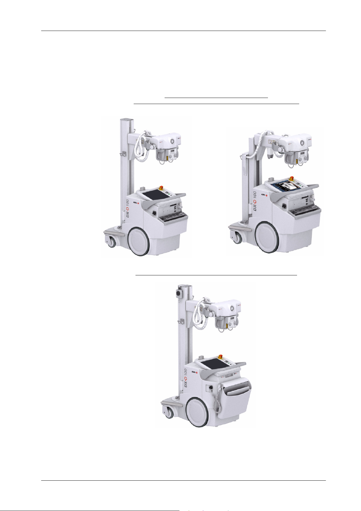
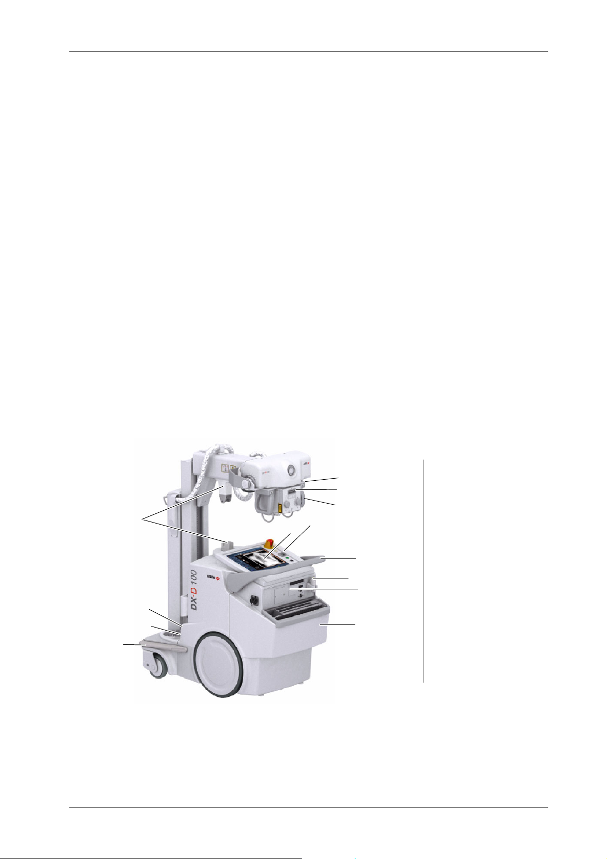
Illustration 1-1
DX-D 100 Mobile X-ray Unit
DX-D 100 Mobile X-ray Unit
User Manual
(1)
with Standard Column (1) / with Telescopic Column, optional
Configuration for Wireless DR Detector:
(2)
(2)
Configuration for Portable DR Detector, with Standard
Column
0188K EN 20201116
3
Page 12

DX-D 100 Mobile X-ray Unit
User Manual
1.1 GENERAL FEATURES
The main features of this Unit are:
A solid and ergonomic design. Ease of operation; security and precision
Standard electrical outlet operation with single-phase lines at 100 / 110 /
Independent operation without mains connection (Stand-Alone). In
Constant potential high frequency.
Controls at the Handlebar and Tube-Collimator Assembly for motorized
of all positioning movements relative to the patient.
120 / 127 / 220 / 230 / 240 V~. Automatic line voltage compensation.
normal operating conditions, the Battery Charger keeps batteries stable
and fully charged, provided the Unit is connected to the mains ( charging).
movements of the equipment.
Controls for lock release of Rotating Column (Standard or Telescopic)
and Telescopic Arm. Column rotation in relation to its vertical axis
o
(¦317
), telescopic and vertical motion of the Arm.
Tube-Collimator Assembly rotation in relation to its transverse axis
o
) and horizontal axis (120o). Collimator rotation in relation to its
(360
vertical axis (180
o
).
Operation Control through the NX application and the Software C onsole.
X-ray Handswitch for X-ray exposures.
Remote infrared X-ray Handswitch (optional).
Dosimetry (optional).
Manual Collimation.
Heat Unit storage for the X-ray Tube, even after turning ON/OFF the
equipment.
Tube protection circuitry prolongs Tube life and increases system
performance.
Equipped with closed loop control of X-ray Tube current, kVp and
filaments, which minimize potential errors and the need for
readjustments.
4
0188K EN 20201116
Page 13

1.2 PRODUCT IDENTIFICATION
To provide manufacturer and product information, each major item in the
equipment has identification labels attached. The labels contain the following
information:
Manufacturer.
Product.
Model, serial number and date of manufacture.
Voltage (V), Input Power (kVA), Frequency (Hz) and Output Power (kW).
Inherent Filtration.
Mass.
DX-D 100 Mobile X-ray Unit
User Manual
Certifications and Symbols.
Place and date of manufacture.
0188K EN 20201116
* The Label data can vary, depending on the DX-D 100 Mobile X -ray Unit model
5
Page 14

DX-D 100 Mobile X-ray Unit
User Manual
1.3 INDICATIONS FOR USE
1.3.1 INTENDED USE
This equipment is intended for use by qualified personnel only.
The DX-D 100 Mobile X-ray Unit is an equipment designed for general
radiography in hospitals, clinics, radiology imaging centers and medical
practices to perform processes and provide X-ray radiographic images of the
skeleton, skull, chest, spine, pelvis, lung, abdomen, extremities and other body
parts on the patients.
Images can be obtained with the patient in the sitting, standing or lying position.
Examinations can be performed to any kind of patient group. Patients may be
physically able, disabled, immobilized or in a state of shock.
This DX-D 100 Mobile X-ray Unit contributes to the metrics of imaging
performance ensuring the efficient use of radiation.
The X-Ray image receptors used in this unit are Digital Detectors.
1.3.2 NORMAL U SE
The Normal Use of this equipment is defined as the Intended Use plus the
Maintenance and Service tasks.
1.3.3 CONTRAINDICATIONS
Do not use the equipment for any purposes other than those for which it is
intended. Operation of the equipment for unintended purposes could lead to
fatal or other serious injury.
This equipment is not intended for mammographic applications.
If children are to be examined, they should always be accompanied by an adult.
6
0188K EN 20201116
Page 15

DX-D 100 Mobile X-ray Unit
User Manual
SECTION 2 SAFETY AND REGULATORY INFORMATION
This section describes the safety considerations, general precautions for
patient, operator and equipment in order to perform a safe operation and
service tasks.
Regulatory information and symbols used in the equipment are detailed in this
section to operate it safely.
2.1 GENERAL
FOR CONTINUED SAFE USE OF THIS EQUIPMENT FOLLOW
THE INSTRUCTIONS IN THIS OPERATING MANUAL. BOTH
OPERATOR AND SERVICE PERSONNEL HAVE TO STUDY
THIS MANUAL CAREFULLY, INSTRUCTIONS HEREIN
SHOULD BE THOROUGHLY READ AND UNDERSTOOD
BEFORE ATTEMPTING TO PLACE THE EQUIPMENT IN
OPERATION, ESPECIALLY THE INSTRUCTIONS
CONCERNING SAFETY, REGULATIONS, DOSAGE AND
RADIATION PROTECTION. KEEP THIS OPERATINGMANUAL
WITH THE EQUIPMENT AT ALL TIMES AND PERIODICALLY
REVIEW THE OPERATING AND SAFETY INSTRUCTIONS.
TECHNICAL INSTRUCTIONS FOR SERVICE PERSONNEL
SUCH AS INSTALLATION, CALIBRATION OR MAINTENANCE
ARE DESCRIBED IN THE RESPECTIVE CHAPTERS OF THE
SERVICE MANUAL PROVIDED WITH THIS EQUIPMENT.
PLEASE STUDY THIS MANUAL AND THE MANUALS FOR
EACH SYSTEM COMPONENT TO BE FULLY AWARE OF ALL
THE SAFETY AND OPERATIONAL REQUIREMENTS.
0188K EN 20201116
7
Page 16

DX-D 100 Mobile X-ray Unit
User Manual
OPERATOR AND SERVICE PERSONNEL AUTHORIZED TO
USE, INSTALL, CALIBRATE AND MAINTAIN THIS
EQUIPMENT MUST BE AWARE OF THE DANGER OF
EXCESSIVE EXPOSURE TO X-RAY RADIATION. IT IS
VITALLY IMPORTANT THAT EVERYONE WORKING WITH
X-RAY RADIATION IS PROPERLY TRAINED, INFORMED ON
THE HAZARDS OF RADIATION AND TAKE ADEQUATE
STEPS TO ENSURE PROTECTION AGAINST INJURY.
OPERATOR MUST HAVE SUFFICIENT KNOWLEDGE TO
COMPETENTLY PERFORM THE DIFFERENT DIAGNOSTIC
IMAGING PROCEDURES WITH X-RAY DEVICES. THIS
KNOWLEDGE IS ACQUIRED THROUGH A VARIETY OF
EDUCATIONAL METHODS INCLUDING CLINICAL WORKING
EXPERIENCE, AND AS PART OF MANY COLLEGE AND
UNIVERSITY RADIOLOGIC TECHNOLOGY PROGRAMS IN
ACCORDANCE WITH LOCAL LAWS OR REGULATIONS.
SERVICE PERSONNEL MUST HAVE SUFFICIENT
KNOWLEDGE TO COMPETENTLY PERFORM THE SERVICE
TASKS RELATED TO X-RAY DEVICES AND PARTICULARLY
TO THE EQUIPMENT DESCRIBED IN THIS MANUAL. THIS
KNOWLEDGE IS ACQUIRED THROUGH A VARIETY OF
EDUCATIONAL METHODS FOR TECHNICIANS IN
ACCORDANCE WITH LOCAL LAWS OR REGULATIONS,
INCLUDING SPECIFIC TRAINING ON THIS EQUIPMENT.
X-RAY EQUIPMENT IS DANGEROUS TO BOTH PATIENT AND
OPERATOR UNLESS PROTECTION MEASURES ARE
STRICTLY OBSERVED. IF THE EQUIPMENT IS NOT
ACCURATELY USED, IT MAY CAUSE INJURY.
ALTHOUGH X-RADIATION CAN BE HAZARDOUS, X-RAY
EQUIPMENT DOES NOT POSE ANY DANGER WHEN IT IS
PROPERLY USED.
8
0188K EN 20201116
Page 17
DX-D 100 Mobile X-ray Unit
User Manual
SPECIAL ATTENTION MUST BE GIVEN TO DIAGNOSTIC
X-RAY EQUIPMENT SPECIFIED TO BE USED IN
COMBINATION WITH ACCESSORIES OR OTHER ITEMS. BE
AWARE OF POSSIBLE ADVERSE EFFECT ARISING FROM
THESE MATERIALS LOCATED IN THE X--RAY BEAM (SEE
THE TABLE BELOW FOR THE MAXIMUM EQUIVALENT
ATTENUATION OF MATERIALS POSSIBLY LOCATED IN THE
X-RAY BEAM).
MAXIMUM ATTENUATION EQUIVALENT mm AL
ITEM
21 CFR
Total of all layers composing the front panel of cassette holder 1.2 1.2
Total of all layers composing the front panel of FILM CHANGER 1.2 1.2
Total of all layers, excluding detector itself, composing the front
panel of DIGITAL X-RAY IMAGING DEVICE
Cradle 2.3 2.3
PATIENT SUPPORT, stationary, without articulated joints 1.2 1.2
PATIENT SUPPORT, movable, without articulated joints (including
stationary layers)
PATIENT SUPPORT, with radiolucent panel having one articulated
joint
PATIENT SUPPORT, with radiolucent panel having two or more
articulated joints
PATIENT SUPPORT, cantilevered 2.3 2.3
1.2 1.2
1.7 1.7
1.7 1.7
2.3 2.3
IEC 60601-2-54:2009
and
IEC 60601-2-54:2009+AMD1:2015
Note 1.-- Devices such as RADIATION DETECTORS are not included in the item listed in this table.
Note 2.-- Requirements concerning the ATTENUATION properties of RADIOGRAPHIC CASSETTES and of INTENSIFYING
SCREENS are given in ISO 4090 [3], for ANTI --SCATTER GRIDS in IEC 60627[1].
Note 3.-- ATTENUATION caused by table mattresses and similar accessories is not included in the maximum ATTENUATION
EQUIVALENT for PATIENT SUPPORT.
Note 4.-- Maximum ATTENUATION EQUIVALENT mm Al is only applied to the corresponding item. If several items given in this table
are located in the path of the X-RAY BEAM between the PATIENT and the X-RAY IMAGE RECEPTOR, each corresponding maximum
ATTENUATION EQUIVALENT mm Al is separately applied to each i tem.
0188K EN 20201116
9
Page 18
DX-D 100 Mobile X-ray Unit
User Manual
2.2 RESPONSIBILITIES
THIS X-RAY UNIT MAY BE DANGEROUS TO PATIENT AND
OPERATOR UNLESS SAFE EXPOSURE FACTORS,
OPERATING INSTRUCTIONS AND MAINTENANCE
SCHEDULES ARE OBSERVED.
THE EQUIPMENT HEREIN DESCRIBED IS SOLD WITH THE
UNDERSTANDING THAT THE MANUFACTURER, ITS
AGENTS, AND REPRESENTATIVES ARE NOT LIABLE FOR
INJURY OR DAMAGE WHICH MAY RESULT FROM
OVEREXPOSURE OF PATIENTS OR PERSONNEL TO X-RAY
RADIATION.
THE MANUFACTURER DOES NOT ACCEPT ANY
RESPONSIBILITY FOR OVEREXPOSURE OF PATIENTS OR
PERSONNEL TO X-RAY RADIATION GENERATED BY THIS
EQUIPMENT WHICH IS A RESULT OF POOR OPERATING
TECHNIQUES OR PROCEDURES.
NO RESPONSIBILITY WILL BE A SSUMED FOR ANY
EQUIPMENT THAT HAS NOT BEEN SERVICED AND
MAINTAINED IN ACCORDANCE WITH THE MANUFACTURER
INSTRUCTIONS, OR WHICH HAS BEEN MODIFIED OR
TAMPERED WITH IN ANY WAY.
IT IS THE RESPONSIBILITY OF THE OPERATOR TO ENSURE
THE SAFETY OF THE PATIENT WHILE THE X-RAY
EQUIPMENT IS IN OPERATION, BY VISUAL OBSERVATION,
PROPER PATIENT POSITIONING AND USE OF THE DEVICES
THAT ARE INTENDED TO PREVENT PATIENT INJURY.
ALWAYS WATCH ALL PARTS OF THE SYSTEM TO VERIFY
THAT THERE IS NEITHER INTERFERENCE NOR
POSSIBILITY OF COLLISION WITH THE PATIENT OR WITH
OTHER EQUIPMENTS.
10
0188K EN 20201116
Page 19

DX-D 100 Mobile X-ray Unit
User Manual
IT IS THE RESPONSIBILITY OF THE PURCHASER
/CUSTOMER TO PROVIDE THE MEANS FOR AUDIO AND
VISUAL COMMUNICATION BETWEEN THE OPERATOR AND
THE PATIENT.
IT IS THE RESPONSIBILITY OF THE OPERATOR TO ENSURE
THAT ALL THE EXPOSURE PARAMETERS ARE CORRECT
BEFORE PERFORMING AN EXAM TO THE PATIENT, BY
VERIFYING THAT THE PARAMETER SELECTION HAS NOT
BEEN MODIFIED UNINTENTIONALLY OR BY THE C ONTACT
OF EXTERNAL ELEMENTS ON THE CONTROL CONSOLE, IN
ORDER TO AVOID THE OVEREXPOSURE OR THE NEED OF
PERFORMING A NEW EXAM TO THE PATIENT.
MAKE SURE THAT THE X-RAY TUBE IS SET IN WORKING
POSITION WITH THE REFERENCE AXIS (X-RAY BEAM)
POINTING TO THE RECEPTION AREA.
2.3 MAXIMUM PERMISSIBLE DOSE (MPD)
Before operation, people qualified and authorized to operate this equipment
should be familiar with the Recommendations of the International Commission
on Radiological Protection, contained in Annals Number 60 of the ICRP, with
applicable National Standards and should have been trained in use of the
equipment.
THE OPERATOR SHALL USE THE LARGEST POSSIBLE
DISTANCE FROM THE FOCAL SPOT TO SKIN IN ORDER TO
KEEP THE ABSORBED DOSE AS LOW AS REASONABLY
ACHIEVABLE.
0188K EN 20201116
11
Page 20

DX-D 100 Mobile X-ray Unit
User Manual
2.4 RADIATION PROTECTION
Although this equipment is built to the highest safety standards and
incorporates a high degree of protection against X-radiation other than the
useful beam, no practical design of equipment can provide complete protection,
nor can any practical design compel the operator to take adequate precautions
to prevent the possibility of any persons carelessly, unwisely, or unknowingly
exposing themselves or others to X-radiation.
IT IS THE RESPONSIBILITY OF THE OPERATOR TO
RESTRICT THE ACCESS TO THE UNIT IN ACCORDANCE
WITH LOCAL REGULATIONS FOR RADIATION
PROTECTION.
Because exposure to X-ray radiation can be damaging to the health, use great
care to ensure protection against exposure to the primary beam. Some of the
effects of X-ray radiation are cumulative and may extend over a period of
months or years. The best safety rule for an X-ray operator is “Avoid exposure
to the primary beam at all times
”.
Any object in the path of the primary beam produces secondary (scattered)
radiation. The intensity of secondary radiation depends on the energy and
intensity of the primary beam and the atomic number of the object material
struck by the primary beam. Secondary radiation may be of greater intensity
than that of the radiation reaching the receptor. Take protective measures to
safeguard against it.
An effective protective measure is the use of lead shielding. To minimize
dangerous exposure, use such items as lead screens, lead impregnated
gloves, aprons, thyroid collars, etc. Lead screens should contain a minimum of
2.0 mm of lead or equivalent and personal protective devices (aprons, gloves,
etc.) must contain a minimum of 0.25 mm of lead or equivalent. For confirmation
of the local requirements at your site, please r efer to your “Local Radiation
Protection Rules” as provided by your Radiation Protection Advisor.
12
0188K EN 20201116
Page 21

DX-D 100 Mobile X-ray Unit
User Manual
Observe the following rules for radiation protection of the
personnel in the examination room during X-ray exposures:
- Wear radiation protective clothing.
- Wear a personal dosimeter.
- Use the different recommended protective materials and
devices against radiation.
- While operating or servicing X-ray equipment, always keep
as large a distance as possible from the Focal Spot and X-ray
beam, never shorter than 2 meters, protect body and do not
expose hands, wrists, arms or other parts of the body to the
primary beam.
- Protect the patient against radiation outside the area of
interest by using protection accessories.
- Use the smallest X-ray field collimation. Make sure that the
area of interest will be completely exposed and the X-ray field
does not exceed the area of interest.
- Select a Focal Spot to patient skin distance (SID) as large
as possible to keep the absorbed dose for the patient as low
as reasonably possible.
The radiation dose decreases or increases according to the
Focal Spot to Receptor distance (SID: Source to Image
Distance): the greater the SID distance, the lower the
radiation dose. The radiation dose is inversely proportional
to the distance squared.
- Select as short an examination time as possible. This will
reduce total radiation dose considerably.
- Use Grids whenever possible.
- Place the region of interest as close as possible to the
image receptor. This will reduce exposure to radiation and
optimize the exposure.
0188K EN 20201116
- Be sure that audible and visual communication between
the patient and operator is established throughout the entire
examination.
13
Page 22

DX-D 100 Mobile X-ray Unit
User Manual
2.5 MONITORING OF PERSONNEL
Monitoring of personnel to determine the amount of radiation to which they have
been exposed provides a valuable cross check to determine whether or not
safety measures are adequate. It may reveal inadequate or improper radiation
protection practices and potentially serious radiation exposure situations.
The most effective method of determining whether or not the existing protective
measures are adequate is the use of instruments to measure the exposure.
These measurements should be taken at all locations where the operator, or
any portion of the body may be exposed. Exposure must never exceed the
accepted tolerable dose.
A frequently used, but less accurate, method of determining the amount of
exposure is the placement of film at strat egic locations. After a specified period
of time, develop the film to determine the amount of radiation.
A common method of determining whether personnel have been exposed to
excessive radiation is the use of personal radiation dosimeters. These consist
of X-ray sensitive film or thermoluminescent material enclosed within a holder
that may be worn on the body. Even though this device only measures the
radiation which reaches the area of the body on which they are worn, they do
provide a reasonable indication of the amount of radiation received.
14
0188K EN 20201116
Page 23
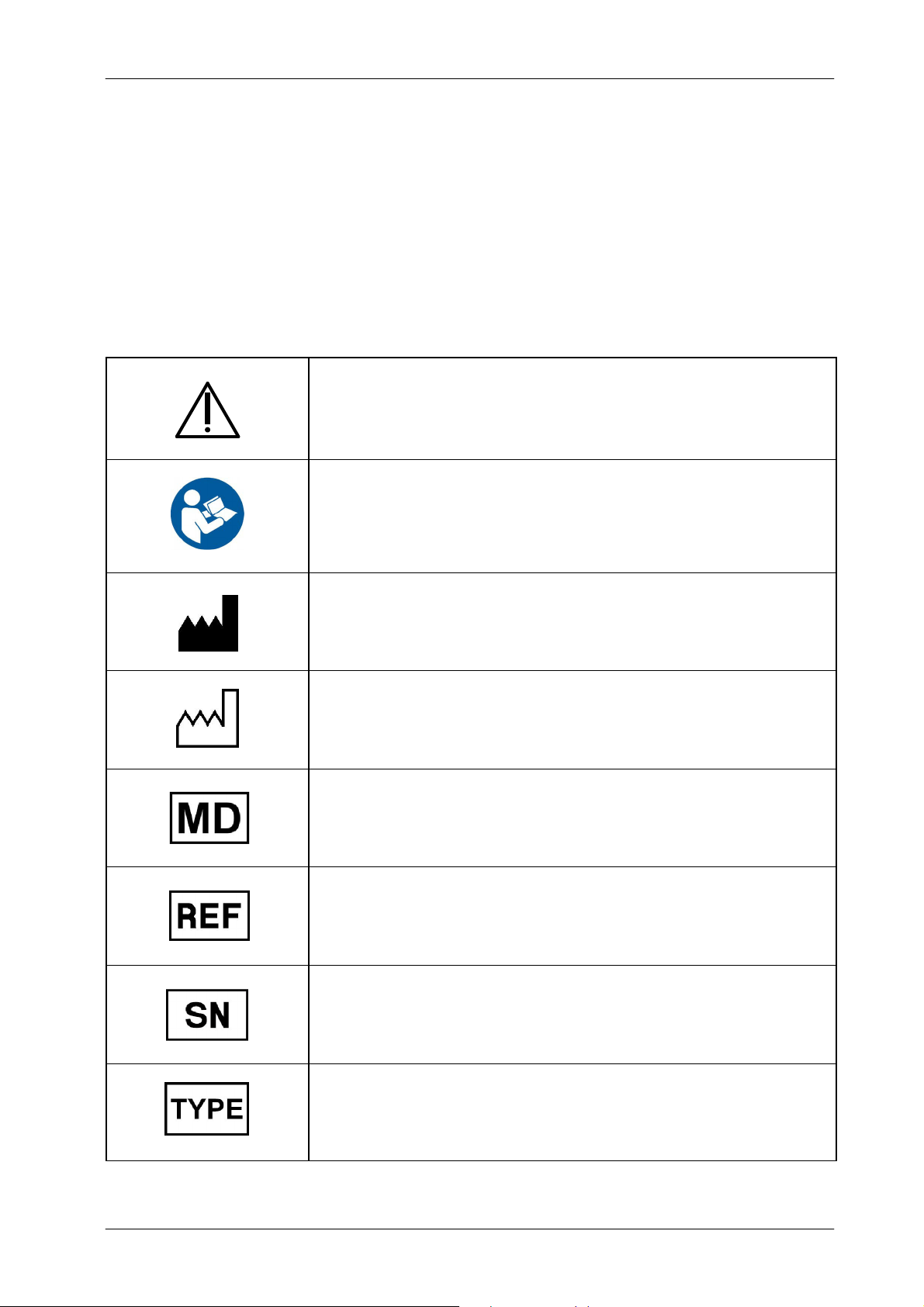
2.6 SAFETY SYMBOLS
The following safety symbols may appear in the equipment.
Their meaning are described below.
DX-D 100 Mobile X-ray Unit
User Manual
Caution. Consult accompanying documents.
Safety Symbol. Follow instructions for use, especially those
instructions identified with Advisory Symbols to avoid any
risk for the Patient or Operator.
(Only applies to Standard IEC 60601-1:2005 and
IEC 60601-1:2005+AMD1:2012)
Manufacturer.
Date of Manufacture.
Medical Device.
Catalogue Number (Model reference).
Serial Number.
0188K EN 20201116
Model Configuration.
15
Page 24
DX-D 100 Mobile X-ray Unit
User Manual
IPX0
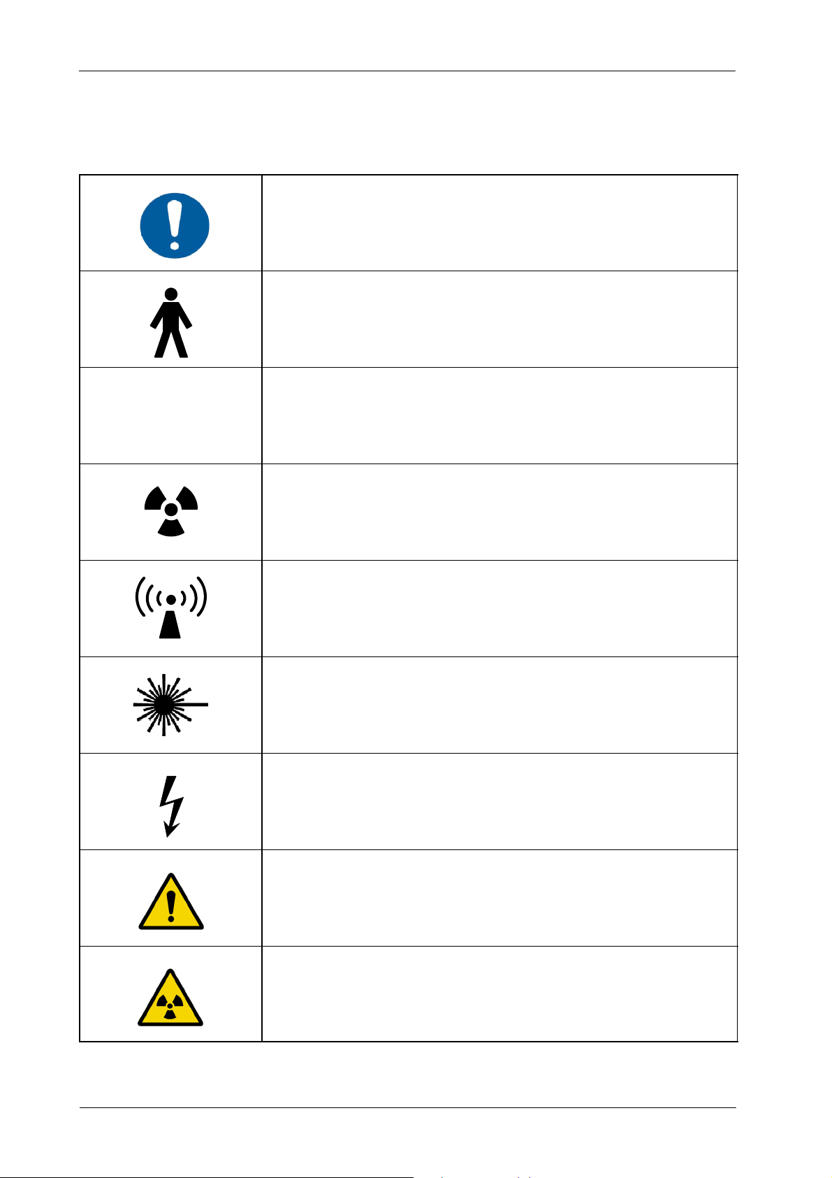
General Mandatory action.
Type B applied part.
Protection against harmful ingress of water or particulate matter.
IP Classification: Ordinary.
Ionizing radiation.
Non-ionizing electromagnetic radiation.
Radiation of Laser apparatus.
Do not stare into beam.
(Only applicable to equipment with Laser Pointer)
Dangerous voltage.
General warning, caution, risk of danger.
16
Warning: Ionizing radiation.
0188K EN 20201116
Page 25

Warning: Non-ionizing radiation.
Warning: Laser beam.
Warning: Electricity.
DX-D 100 Mobile X-ray Unit
User Manual
Warning: Do not place fingers between mobile and fixed parts of the
equipment, it may cause serious injuries to patient or operator.
As well, make sure the patient extremities are correctly positioned
into limit areas during operation, movement of parts may cause
serious damages to patient.
Electrostatic sensitive devices.
No pushing.
No sitting.
0188K EN 20201116
No stepping on surface.
Do not handle.
17
Page 26
DX-D 100 Mobile X-ray Unit
User Manual
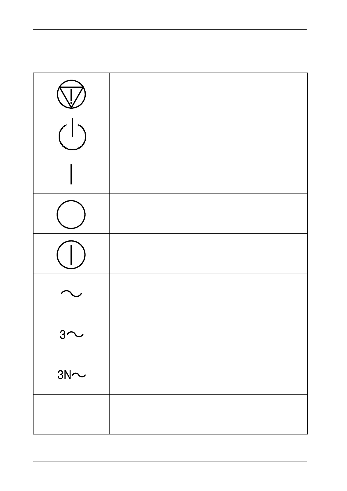
Emergency stop.
“Stand-by” power.
(Only applies to IEC 60601-1:2005 and IEC 60601-1:2005+AMD1:2012)
“ON” power.
“OFF” power.
“ON” / “OFF” (push-push).
Each position, “ON” or “OFF”, is a stable position.
Alternating current.
Three-phase alternating current.
Three-phase alternating current with neutral conductor.
18
N
Connection point for the neutral conductor on Permanently Installed
equipment.
0188K EN 20201116
Page 27

Direct current.
Both direct and alternating current.
Protective Earth (Ground).
DX-D 100 Mobile X-ray Unit
User Manual
Li/Pb/Cd/Hg
Earth (Ground).
This symbol according to the European Directive indicates that the
Waste of Electrical and Electronic Equipment (WEEE) must not be
disposed of as unsorted municipal waste and must be collected
separately. Please contact an authorized representative of the
manufacturer or an authorized waste management company for
information concerning the decommissioning of your equipment.
This separate collection symbol is affixed to a battery or its packing,
to advise that the battery must be recycled or disposed of in
accordance with local or country laws. The letters below the symbol
indicate whether certain elements (Li=Lithium, PB=Lead,
CD=Cadmium, Hg=Mercury) are contained in the battery. All batteries
removed from the equipment must be properly recycled or disposed.
Please contact an authorized representative of the manufacturer or
an authorized waste management company for information
concerning the decommissioning of your equipment.
Pollution Control. (Only applicable to People’s Republic of China (PRC)).
This symbol indicates the product contains hazardous materials in
excess of the limits established by the Chinese Standards. It must not
be disposed of as unsorted municipal waste and must be collected
separately. Please contact an authorized representative of the
manufacturer or an authorized waste management company for
information concerning the decommissioning of your equipment.
0188K EN 20201116
19
Page 28

DX-D 100 Mobile X-ray Unit
User Manual
2.7 REGULATORY INFORMATION
2.7.1 CERTIFICATIONS
The DX-D 100 Mobile X-ray Unit covered by this Operation Manual is
authorized to be marked with CE MARKING in accordance with the provisions
of the Council Directive 93/42/EEC as amended by 2007/47/EEC concerning
Medical Devices.
Statement of Compliance with IEC 60601-1-3: DX-D 100 Mobile X-ray Unit
with radiation protection in accordance with IEC 60601-1-3:1994, IEC
60601-1-3:2008 and IEC 60601-1-3:2008+AMD1:2013.
Statement of Compliance with IEC 60601-2-54: DX-D 100 Mobile X-ray U nit
for Radiography and/or Radioscopy in accordance with IEC 60601-2-54:2009
and IEC 60601-2-54:2009+AMD1:2015.
Statement of Compliance with 21CFR Subchapter J: This DX-D 100 Mobile
X-ray Unit conforms to DHHS radiation Standards of 21CFR subchapter J as
of the date of manufacture.
2.7.2 ENVIRONMENTAL STATEMENT ON THE LIFE CYCLE OF THE EQUIPMENT OR SYSTEM
This equipment or system contains environmentally dangerous components
and materials (such as PCBs, electronic components, used dielectric oil, lead,
batteries etc.) which, once the life-cycle of the equipment or system comes to
an end, becomes dangerous and need to be considered as harmful waste
according to the international, domestic and local regulations.
The manufacturer recommends to contact its authorized representative or an
authorized waste management company once the life-cycle of the equipment
or system comes to an end to remove this equipment or system.
2.7.3 MODE OF OPERATION
Continuous operation with intermittent loading, in accordance w ith
Standard IEC 60601--1:1988.
20
Continuous operation, in accordance with Standard IEC 60601-1:2005
and IEC60601-1:2005+AMD1:2012.
0188K EN 20201116
Page 29

2.7.4 PROTECTION AGAINST ELECTRIC SHOCK HAZARDS
Protection against electric shock hazards in accordance with Standards: IEC
60601-1:1988; IEC 60601-1:2005 and IEC 60601-1:2005+AMD1:2012, IEC
60601-2-54:2009 and IEC 60601-2-54:2009+AMD1:2015.
DX-D 100 Mobile X-ray Unit
User Manual
This equipment has been classified as a type-B (
) device, in accordance with
Standard IEC 60601--1 requirements: Class I -- Type B applied parts.
TO AVOID THE RISK OF ELECTRIC SHOCK, THIS
EQUIPMENT MUST ONLY BE CONNECTED TO A SUPPLY
MAINS WITH PROTECTIVE EARTH.
ACCORDING TO MDD/93/42/EEC, AS AMENDED BY
2007/47/EEC, THIS UNIT IS EQUIPPED WITH EMC FILTERS.
THE LACK OF PROPER GROUNDING MAY PRODUCE
ELECTRICAL SHOCK TO THE USER.
2.7.5 PROTECTION AGAINST HARMFUL INGRESS OF WATER OR PARTICULATE MATTER
Protection against harmful ingress of water or particulate matter: Ordinary
(IPx0), in accordance with Standard IEC 60601-1:1988, IEC 60601-1:2005 and
IEC 60601-1:2005+AMD1:2012.
2.7.6 PROTECTION AGAINST HAZARDS OF IGNITION OF FLAMMABLE ANAESTHETIC
MIXTURES
Degree of Safety in the presence of Flammable Anesthetics Mixture with air or
with oxygen or with nitrous oxide: Not suitable for use in the presence of
Flammable Anesthetics Mixture with air or with oxygen or with nitrous oxide,in
accordance with Standard IEC 60601-1:1988, IEC 60601-1:2005 and IEC
60601-1:2005+AMD1:2012.
2.7.7 PROTECTION AGAINST HAZARDS FROM UNWANTED OR EXCESSIVE RADIATION
Protection against hazards from unwanted or excessive radiation in
accordance with Standards IEC 60601-1:1988, IEC 60601-1:2005 and IEC
60601-1:2005+AMD1:2012, and IEC 60601-1-3:1994, IEC 60601-1-3:2008
and IEC 60601-1-3:2008+AMD1:2013.
0188K EN 20201116
21
Page 30

DX-D 100 Mobile X-ray Unit
User Manual
2.7.8 DESIGNATED SIGNIFICANT ZONES OF OCCUPANCY
X-Ray equipment specified for any radiological examination that requires the
operator or staff to be close to the patient during normal use (a.e. some pediatric
examinations or other types of examinations for patients that may require
assistance), shall have at least one “Significant Zone of Occupancy” for the use
of the operator and staff, designated as follows:
Illustration 2-1
Radiographic Examination on the Chest Unit or Front Panel
CHEST UNIT
S
S = SIGNIFICANT ZONE OF OCCUPANCY
MINIMUM AREA 60 x 60 cm
MINIMUM HEIGHT ABOVE THE FLOOR 200 cm
Focal Spot
S
Dosimeter
d = DISTANCE FROM THE AXIS OF THE X-RAY
BEAM TO THE DOSIMETER
SIGNIFICANT ZONE OF OCCUPANCY
AT THE LEFT SIDE OF THE CHEST UNIT
d
Focal Spot
140 cm
CHEST UNIT
S1
Phantom
MOBILE X--RAY UNIT
Protective Device
Wall
Patient Support
X-- Ray Receptor
S2
SIGNIFICANT ZONE OF OCCUPANCY
AT THE RIGHT SIDE OF THE CHEST UNIT
22
SID 100 cm
Focal Spot
MOBILE X--RAY UNIT
0188K EN 20201116
Page 31

Illustration 2-2
Radiographic Examination on any Patient Support or any Table
Focal Spot
Phantom
X-- Ray Receptor
DX-D 100 Mobile X-ray Unit
User Manual
MOBILE X--RAY UNIT
SID 100 cm
S
S = SIGNIFICANT ZONE OF OCCUPANCY
MINIMUM AREA 60 x 60 cm
MINIMUM HEIGHT ABOVE THE FLOOR 200 cm
Focal Spot
S
Dosimeter
d = DISTANCE FROM THE AXIS OF THE X-RAY
BEAM TO THE DOSIMETER
d
Patient Support
RAD TABLE
SIGNIFICANT ZONE OF OCCUPANCY
AT FRONT SIDE OF THE MOBILE UNIT
SIGNIFICANT ZONE OF OCCUPANCY
AT THE RIGHT SIDE OF THE MOBILE UNIT
(CATHODE)
S4
RAD TABLE
S3
Focal Spot
S5
MOBILE X--RAY UNIT
0188K EN 20201116
SIGNIFICANT ZONE OF OCCUPANCY
AT THE LEFT SIDE OF THE MOBILE UNIT
(ANODE)
23
Page 32

DX-D 100 Mobile X-ray Unit
User Manual
2.7.9 DISTRIBUTION OF STRAY RADIATION
Measurement conditions to determine the distribution of Stray Radiation in the
Significant Zone of Occupancy are in accordance with Standard IEC
60601-1-3:1994, IEC 60601-1-3:2008 and IEC 60601-1-3:2008+AMD1:2013.
Exposure Parameters: RAD mode, 150 kVp, 20 mAs.
Collimator opening for Field Size 18 x 18 cm, SID 100 cm.
Phantom: Rectangular water phantom of 25 x 25 x 15 cm, or a material
having a similar X-Ray attenuation coefficient.
Note .
Radiation measuring instrument: Low Radiation Dosimeter.
The results have been obtained with a configuration that is
representative of the worst case within the different configurations
of the unit.
Refer to Illustration 2-1 for position of the X-ray Unit during radiographic
examination on the Chest Unit or Front Panel, and refer to Illustration 2-2 for
position of the X-ray Unit during radiographic examination on any Patient
Support or any Table.
The following illustrations show the Distribution of Stray Radiation in each
examination position.
24
0188K EN 20201116
Page 33

Illustration 2-3
Distribution of Stray Radiation on Chest Unit or Front Panel
200
180
160
140
120
100
80
HEIGHT ABOVE FLOOR (cm)
60
DX-D 100 Mobile X-ray Unit
User Manual
40
20
0
0 500 1000 1500 2000 2500 3000 3500 4000 4500 5000 5500 6000 6500
STRAY RADIATION (μGy/h)
SIGNIFICANT ZONE OF OCCUPANCY
AT THE LEFT SIDE OF THE CHEST UNIT
S1
S1
S2
S2
d=50cm
1
d = 100 cm
2
d=50cm
1
d = 100 cm
2
CHEST UNIT
S1
Protective Device
Wall
Patient Support
X-- Ray Receptor
Phantom
d
d
S2
SIGNIFICANT ZONE OF OCCUPANCY
AT THE RIGHT SIDE OF THE CHEST UNIT
0188K EN 20201116
SID 100 cm
Focal Spot
MOBILE X--RAY UNIT
25
Page 34

DX-D 100 Mobile X-ray Unit
User Manual
Illustration 2-4
Distribution of Stray Radiation on any Patient Support or any Table
200
180
160
140
120
100
80
HEIGHT ABOVE FLOOR (cm)
60
40
20
0
0 500 1000 1500 2000 2500 3000 3500 4000 4500 5000 5500 6000 6500 7000 7500 8000 8500 9000 950010000
STRAY RADIATION (μGy/h)
SIGNIFICANT ZONE OF OCCUPANCY
AT THE RIGHT SIDE OF THE MOBILE UNIT
(CATHODE)
S4
S3
S3
S4
S4
S5
S5
1
2
1
2
1
2
d=50cm
d = 100 cm
d=50cm
d = 100 cm
d=50cm
d = 100 cm
SIGNIFICANT ZONE OF OCCUPANCY
AT FRONT SIDE OF THE MOBILE UNIT
S3
Focal Spot
RAD TABLE
d
d
d
MOBILE X--RAY UNIT
S5
26
SIGNIFICANT ZONE OF OCCUPANCY
AT THE LEFT SIDE OF THE MOBILE UNIT
(ANODE)
0188K EN 20201116
Page 35

2.8 ELECTROMAGNETIC COMPATIBILITY (EMC)
This equipment generates, uses, and can radiate radio frequency energy.
The equipment may cause radio frequency interference t o
other medical or non medical devices and radio
communications.
To provide reasonable protection against such interference, this product
complies with emissions limits for a Group 1 -- Class A Medical Devices
Directive as stated in IEC 60601-1-2:2007 and IEC 60601-1-2:2014. However,
there is no guarantee that interference will not occur in a particular installation.
If this equipment is found to cause interference (which may be determined by
turning the equipment on and off), the operator (or qualified service personnel)
should attempt to correct the problem by one or more of the following measures:
DX-D 100 Mobile X-ray Unit
User Manual
reorient or relocate the affected device,
increase the separation between the equipment and the affected device,
power the equipment from a source different from that of the affected
device,
consult the service engineers for further suggestions.
To comply with the regulations applicable to an electromagnetic interference for
a Group 1 -- Class A Medical Device, all interconnect cables to peripheral
devices must be shielded and properly grounded. Use of cables not properly
shielded and grounded may result in the equipment causing radio frequency
interference in violation of the European Union Medical Device Directive and of
Federal Communications Commission regulations (FCC).
Before using this equipment make sure that all requirements
about EMC included in this manual are accomplished.
0188K EN 20201116
Should any interference (EMC) be detected with other
equipment, please position the other equipment away from
this one.
27
Page 36

DX-D 100 Mobile X-ray Unit
ThisX
b
lef
l
l
f
supplynetworkthatsuppliesbuildingsusedfor
User Manual
It is customer responsibility to assure that this equipment
and vicinity equipment complies the value of radio frequency
interferences shown in General Regulation for safety
according to IEC 60601-1-2:2007 and IEC 60601-1-2:2014
Tables as described in this section.
The manufacturer is not responsible for any interference
caused by using other than recommended interconnect
cables or by unauthorized changes or modifications to this
equipment.
GUIDANCE AND MANUFACTURER’S DECLARATION - ELECTROMAGNETIC EMISSIONS
This X-ray System is intended for use in the electromagnetic environment specified below.
The customer or the user of this X-ray System should assure that it is used in such an environment.
Emissions test Compliance Electromagnetic environment -- guidance
RF emissions
CISPR 11
RF emissions
CISPR 11
Harmonic emissions
IEC 61000--3--2
Voltage fluctuations/flicker emissions
IEC 61000--3--3
NOTE - I n accordance with Standard IEC 60601-1-2:2014, the emissions characteristics of this equipment make it suitable for use in industrial areas and
hospitals (CISPR 11 Class A). If it is used in a residential environment (for which CISPR 11 Class B is normally required) this equipment might not offer
adequate protection to radio-frequency communication services. The user might need to take mitigation measures, such as reloc ating or re-orientating the
equipment.
(IEC 60601-1-2:2007 AND IEC 60601-1-2:2014)
This X-ray System uses RF energy only for its
Group 1
Class A
Class A
Complies
internal function. Therefore, its RF emissions are
very low and are not likely to cause any
interference in nearby electronic equipment.
establishments other than domestic and those
directly connected to the public low--voltage power
supply network that supplies buildings used
domestic purposes.
-raySystemissuita
or useina
or
28
0188K EN 20201116
Page 37

DX-D 100 Mobile X-ray Unit
User Manual
GUIDANCE AND MANUFACTURER’S DECLARATION - ELECTROMAGNETIC IMMUNITY
This X-ray System is intended for use in the electromagnetic environment specified below.
The customer or the user of this X-ray System should assure that it is used in such an environment.
Immunity test
Electrostatic discharge (ESD)
IEC 61000-4-2
Electrical fast transient/burst
IEC 61000-4-4
Surge
IEC 61000--4--5
Voltage dips, short
interruptions and voltage
variations on power supply
input lines.
IEC 61000--4--11
(IEC 60601-1-2:2007)
IEC 60601-1-2:2007
Test Level
¦ 6 kV contact
¦ 8kVair
¦ 2 kV for power supply lines
¦ 1 kV for input/output lines
¦ 1 kV line(s) to line(s)
¦ 2 kV line(s) to earth
<5%U
(> 95 % dip in UT)
T
for 0.5 cycle
40 % U
(60%dipinUT)
T
for 5 cycles
70 % U
(30%dipinUT)
T
for 25 cycles
Compliance
level
¦ 6kV
¦ 8kV
¦ 2kV
¦ 1kV
¦ 1kV
¦ 2kV
>95%
for 0.5 periods
60 %
for 5 periods
30 %
for 25 periods
Electromagnetic environment -- guidance
Floors should be wood, concrete or ceramic tile.
If floors are covered with synthetic material, the
relative humidity should be at least 30%.
Mains power quality should be that of a typical
commercial or hospital environment.
Mains power quality should be that of a typical
commercial or hospital environment.
Mains power quality should be that of a typical
commercial or hospital environment. If the user
of the X-ray System requires continued
operation during power mains interruptions, it is
recommended that the X-ray System be
powered from a uninterruptible power supply or
a battery.
<5%U
(> 95 % dip in UT)
T
>95%
for 250 periods
for 5s
Power frequency (50/60 Hz)
magnetic field
3A/m
(50 Hz)
IEC 61000--4--8
NOTE -- UTis the a.c. mains voltage prior to application of the test level.
3A/m
Power frequency magnetic fields should be at
levels characteristic of a typical location in a
typical commercial or hospital environment.
0188K EN 20201116
29
Page 38

DX-D 100 Mobile X-ray Unit
User Manual
GUIDANCE AND MANUFACTURER’S DECLARATION - ELECTROMAGNETIC IMMUNITY
This X-ray System is intended for use in the electromagnetic environment specified below.
The customer or the user of this X-ray System should assure that it is used in such an environment.
Immunity test
Conducted RF
IEC 61000--4--6
Radiated RF
IEC 61000--4--3
IEC 60601-1-2:2007
Test Level
150kHzto80MHz
80 MHz to 2.5 GHz
(IEC 60601-1-2:2007)
3Vrms
3V/m
Compliance level Electromagnetic environment -- guidance
Portable and mobile RF communications
equipment should be used no closer to any part
of this X-ray System, including cables, than the
recommended separation distance calculated
from the equation applicable to the frequency of
the transmitter.
Recommended separation distance
3Vrms
150kHzto80MHz
3V/m
80 MHz to 2.5 GHz
d = 1.2 P
d = 1.2 P
d = 2.3 P, 800 MHz to 2.5 GHz
where ’P’ is the m aximum output power rating
of the transmitter in watts (W) according to the
transmitter manufacturer and ’d’ i s the
recommended separation distance in meters
(m).
Field strengths from fixed RF transmitters, as
determined by an electromagnetic site
survey
level in each frequency range
, 80 MHz to 800 MHz
a
), should be less than the c ompliance
b
).
Interference may occur in the vicinity of
equipment marked with the following symbol:
NOTE 1 -- At 80 MHz and 800 MHz, the higher frequency range applies.
NOTE 2 -- These guidelines may not apply in all situations. Electromagnetic propagation is affected by absorption and reflection from
structures, objects and people.
a)
Field strengths from fixed transmitters, such as base stations for radio (cellular/cordless) telephones and land mobile radios, amateur
radio, AM and FM radio broadcast and TV broadcast cannot be predicted theoretically with accuracy. To assess the electromagnetic
environment due to fixed RF transmitters, an electromagnetic site survey should be considered. If the measured field strength in the
location in which this X-ray System is used exceeds the applicable RF compliance level above, this X-ray System should be observed
to verify normal operation. If abnormal performance is observed, additional measures may be necessary, such as re-orienting or
relocating this X-ray System.
b)
Over the frequency range 150 kHz to 80 MHz, field strengths should be less than 3 V/m.
30
0188K EN 20201116
Page 39

DX-D 100 Mobile X-ray Unit
User Manual
RECOMMENDED SEPARATION DISTANCES BETWEEN PORTABLE
AND MOBILE RF COMMUNICATIONS EQUIPMENT AND THE X-RAY SYSTEM
This X-ray System is intended for use in an electromagnetic environment in which radiated RF disturbances are c ontrolled.
The customer or the user of this X-ray System can help prevent electromagnetic interference by maintaining a minimum distance
between portable and mobile RF communications equipment (transmitters) and this X-ray System as recommended below,
to the maximum output power of the communications equipment.
(IEC 60601-1-2:2007)
according
Rated maximum output power
oftransmitter
W
0.01 0.12 0.12 0.23
0.1 0.38 0.38 0.73
1 1.2 1.2 2.3
10 3.8 3.8 7.3
100 12 12 23
GMRS device (Professional Walkie--Talkie): 5 W @ 462--467 MHz 2.7
GSM / UMTS cell phone: 2 W @ 850/1700/1900 MHz 3.3
FRS device (Amateur Walkie--Talkie): 500 mW @ 462--467 MHz 0.9
WIFI / Bluetooth devices: 100 mW @ 2400--2500 MHz 0.8
DECT devices (modern cordless phones): 100mW @ 1880--1900 MHz 0.8
Separation distance according to frequency of transmitter
150 KHz to 80 MHz
d = 1.2 P
TYPICAL RF DEVICES (Worst-Case scenario)
Device: Power @ Frequency Recommended distance(m)
80 MHz to 800 MHz
m
d = 1.2 P
800 MHz to 2.5 GHz
d = 2.3 P
RFID reader (3): 10 mW @ 125--150 KHz / 13.56 MHz 0.12
RFID reader (3): 10 mW @ 902--928 MHz / 2400--2500 MHz 0.23
Station transmitter ATSC TV broadcasting: 100 kW @ 54--800 MHz 380
Station transmitter ATSC TV broadcasting: 100 kW @ 800--890 MHz 730
Station transmitter FM radio broadcasting: 100 kW @ 87.5--108 MHz 380
For transmitters rated at a maximum output power not listed above, the recommended separation distance ’d’ in metres (m) can be
estimated using the equation applicable to the frequency of the tr ansmitter, where ’P’ is the maximum output power rating of the
transmitter in watts (W) according to the transmitter manufacturer.
NOTE 1 -- At 80 MHz and 800 MHz, the s eparation distance for the higher frequency range applies.
NOTE 2 -- These guidelines may not apply in all situations. Electromagnetic propagation is affected by absorption and reflection from
structures, objects and people.
NOTE 3 -- RFID chips are typically powered from the electromagnetic field, and therefore only the reader can be regarded as an RF
transmitter.
0188K EN 20201116
31
Page 40

DX-D 100 Mobile X-ray Unit
User Manual
GUIDANCE AND MANUFACTURER’S DECLARATION - ELECTROMAGNETIC IMMUNITY
This X-ray System is intended for use in the electromagnetic environment specified below.
The customer or user of this X-ray System should assure that it is used in such an environment.
Immunity Test
Electrostatic discharge (ESD)
IEC 61000-4-2
Electrical fast transient/burst
IEC 61000-4-4
Surge
IEC 61000-4-5
(IEC 60601-1-2:2014)
IEC 60601-1-2:2014
Test Level
¦ 8 kV contact
¦ 2kV,¦ kV, ¦ 8kV,
¦ 15 kV air
¦ 2 kV for power supply lines
¦ 1 kV for input/output lines
(100 kHz repetition frequency)
¦ 0.5 kV, ¦ 1kV
line(s) to line(s)
¦ 0.5 kV, ¦ 1kV,¦ 2kV
line(s) to earth
0% UTfor 0.5 cycle
o
,45o,90o,135o, 180o,
at 0
o
, 270oand 315
225
o
Compliance Level
¦ 8 kV contact
¦ 2kV,¦ kV, ¦ 8kV,
¦ 15 kV air
¦ 2 kV for power supply lines
¦ 1 kV for input/output lines
(100 kHz repetition frequency)
¦ 0.5 kV, ¦ 1kV
line(s) to line(s)
¦ 0.5 kV, ¦ 1kV,¦ 2kV
line(s) to earth
0% UTfor 0.5 cycle
o
,45o,90o,135o, 180o,
at 0
o
, 270oand 315
225
o
Electromagnetic
environment - guidance
Floors should be wood,
concrete or ceramic tile. If floors
are covered with synthetic
material, the relative humidity
should be at least 30 %.
Mains power quality should be
that of a typical commercial or
hospital environment.
Mains power quality should be
that of a typical commercial or
hospital environment.
Voltage dips, short interruptions
and voltage variations on power
supply input lines.
IEC 61000-4-11
Power frequency (50/60 Hz)
magnetic field
IEC 61000-4-8
0%UTfor 1 cycle
70 % UTfor 25/30 cycles
at 0
at 0
o
o
0% UT250/300 cycles
0%UTfor 1 cycle
70 % UTfor 25/30 cycles
at 0
at 0
o
o
0% UT250/300 cycles
30 A/m 30 A/m
NOTE - UTis the a.c. mains voltage prior to application of the test level.
Mains power quality should be
that of a typical commercial or
hospital environment. If the
user of the This X-ray System
requires continued operation
during power mains
interruptions, it is
recommended that this X-ray
System is powered from an
Uninterruptible Power Supply
or a battery.
Power frequency magnetic
fields should be at levels
characteristic of a typical
location in a typical commercial
or hospital environment.
32
0188K EN 20201116
Page 41

DX-D 100 Mobile X-ray Unit
y
pqp
User Manual
GUIDANCE AND MANUFACTURER’S DECLARATION - ELECTROMAGNETIC IMMUNITY
This X-ray System is intended for use in an electromagnetic environment specified below.
The customer or user of this X-ray System should assure that it is used in such an environment.
Immunity Test
Radiated RF EM fields
IEC 61000-4-3
Proximity fields from RF
wireless Communications
equipment
IEC 61000-4-3
Conducted disturbances
induced by RFfields
IEC 61000-4-6
IEC 60601-1-2:2014
Test Level
3Vrms
from 80 MHz to 2.7 GHz
(80% AM at 1 kHz)
Refer to next table
“IMMUNITY
REQUIREMENTS FOR RF
WIRELESS
COMMUNICATIONS
EQUIPMENT”
3Vrms
from 150 kHz to 80 Mhz
6 Vrms in ISM bands
from 150 kHz to 80 MHz
(80% AM at 1 kHz)
(IEC 60601-1-2:2014)
Compliance Level
3Vrms
from 80 MHz to 2.7 GHz
(80% AM at 1 kHz)
Refer to next table
“IMMUNITY
REQUIREMENTS FOR RF
WIRELESS
COMMUNICATIONS
EQUIPMENT”
3Vrms
from 150 kHz to 80 Mhz
6 Vrms in ISM bands
from 150 kHz to 80 MHz
(80% AM at 1 kHz)
Electromagnetic
environment - guidance
Portable RF communications
equipment (including peripherals such
as antenna cables and external
antennas) should be used no closer
than 30 cm to any part of the equipment,
including cables specified by
manufacturer. Otherwise, degradation
of the performance of this equipment
could result.
NOTE -- The ISM (Industrial, Scientific and Medical) bands between 0.15 MHz and 80 MHz are 6.765 MHz to 6.795 MHz; 13.553 MHz
to 13.567 MHz; 26.957 MHz to 27.283 MHz; and 40.66 MHz to 40.70 MHz.
The amateur radio bands between 0.15 MHz and 80 MHz are 1.8 MHz to 2.0 MHz; 3.5 MHz to 4.0 MHz; 5.3 MHz to 5.4 MHz; 7 MHz
to 7.3 MHz; 10.1 MHz to 10.15 MHz; 14 MHz to 14.2 MHz; 18.07 MHz to 18.17 MHz; 21.0 MHz to 21.4 MHz; 24.89 MHz to 24.99 MHz;
28.0 MHz to 29.7 MHz; and 50.0 MHz to 54.0 MHz.
0188K EN 20201116
33
Page 42

DX-D 100 Mobile X-ray Unit
0.3
User Manual
IMMUNITY REQUIREMENTS TO RF WIRELESS COMMUNICATIONS EQUIPMENT
(IEC 60601-1-2:2014)
This X-ray System is intended for use in an electromagnetic environment specified below.
The customer or User of this X-ray System should assure that it is used in such an environment.
a)
Band
(MHz)
380 -- 390
430 -- 470
Modulation
Pulse modulation
18 Hz
c)
FM
¦5 kHz deviation
b)
b)
Distance
(m)
1kHzsine
704 -- 787
800 -- 960
1700 -- 1990
2400 -- 2570
5100 -- 5800
Pulse modulation
217Hz
Pulse modulation
18Hz
Pulse modulation
217Hz
Pulse modulation
217Hz
Pulse modulation
217Hz
b)
b)
0.3
b)
b)
b)
Immunity Test Level
(V/m)
27
28
9
28
28
28
9
a)
For some services, only the uplink frequencies are included.
b)
The carrier shall be modulated using a 50 % duty cycle square wave signal.
c)
As an alternative to FM modulation, 50 % pulse modulation at 18 Hz may be used because while it does not represent actual
modulation, it would be worst case.
34
0188K EN 20201116
Page 43

2.9 QUANTITATIVE INFORMATION
DX-D 100 Mobile X-ray Unit
User Manual
Note .
2.9.1 FUNCTIONAL TESTS PERFORMED TO OBTAIN THE QUANTITATIVE INFORMATION
Note .
The following tables show the Quantitative Information associated
to this equipment according with the Standard
IEC 60601-1-3:2008 and IEC 60601-1-3:2008+AMD1:2013. This
information illustrates loading factors for image performance and
supplies Dose indication examples. Therefore, these tables are an
instance of the adjustment of Loading Factors, Focal Spot
Selection, SID and Collimator opening, which affect to the
radiation quality or to the radiation dose rate applied in normal use.
Equipment:
These functional tests have been performed with the following
configuration: DR Detector, maximum power X-Ray Tube (50kW)
and Collimator Ralco R221A. The results obtained with this
configuration are representative of the worst case within the
different configurations of the unit.
Instrumentation used:
Dosimeters:
G VacuDAP Compact
G Fluke 481
G Unfors Xi R/F
Thermohygrometer Testo 608--H2.
Water Phantom made of Polymethyl-methacrylate (PMMA) layers:
25 cm x 25 cm x 15 cm.
Test details:
The measurements were made using the most common APR
configurations performed with this unit.
0188K EN 20201116
35
Page 44

DX-D 100 Mobile X-ray Unit
(
)
User Manual
Quantitative Information
Loading Factors Parameter Selection
Patient
examination
(orientative)
CHEST AP 95 160 0.02 3.2 Small 120 35 x 43 No
NECK 85 100 0.02 2 Small 100 24 x 30 No
ABDOMEN AP 80 400 0.025 10 Large 100 35 x 43 No
HIP AP 75 400 0.04 16 Large 100 35 x 43 No
KNEE AP 65 200 0.025 5 Large 100 24 x 30 No
ANKLE AP 60 100 0.04 4 Small 100 24 x 30 No
FOOT AP 60 100 0.032 3.2 Small 100 24 x 30 No
kVp
mA
SID
Time (s)
mAs
Selection
Focal Spot
(cm)
Source-- Image Distance
cm
opening
Collimator blades
Grid
Filtration
HVL (mm Al)
measured value
3.9
(>3.4)
3.7
(>3)
3.5
(>2.9)
3.2
(>2.7)
4.1
(>2.3)
3.8
(>2.1)
3.8
(>2.1)
Measured Doses
(μGy/s)
Phantom
(μGy*m2)
Collimator
Output Dose
(min. value allowed)
27.3 11210 70.4 0.19
12.7 8246 82.45 0.1
59.3 29950 75.87 0.15
82.5 26270 65.67 0.11
9.6 8953 44.56 0.06
4 3973 39.73 0.05
4.5 3204 32.2 0.094
Input Dose Rate
Phantom
(μGy/mAs)
Input Dose
Phantom
(μGy/mAs)
Output Dose
SHOULDER
AP
ELBOW AP 60 100 0.04 4 Small 100 24 x 30 No
WRIST PA 60 100 0.032 3.2 Small 100 24 x 30 No
HAND PA 60 100 0.032 3.2 Small 100 24 x 30 No
75 250 0.04 10 Large 100 24 x 30 No
Note .
Combined standard uncertainty is¦35%
(IEC 60580:2000 / IEC 60601-2-54:2009
and IEC 60601-2-54:2009+AMD1:2015).
3.2
(>2.7)
3.8
(>2.1)
3.8
(>2.1)
3.8
(>2.1)
28 16200 64.61 0.12
6.7 3992 39.7 0.075
5.4 3982 39.4 0.063
5.4 4042 40 0.094
36
0188K EN 20201116
Page 45

2.10 DETERMINISTIC EFFECTS
Deterministic effects may occur when the Radiation dose to a certain organ or
tissue exceeds a specific threshold. Particular organs or tissues of such
concern in diagnostic Radiology are the skin and the eye lens. The numerical
value of the threshold dose is in the range between 1 Gy and 3 Gy.
As shown in the Quantitative Information Tables, the radiation dose effects
measured in this equipment are below the threshold in which the severity of
certain effects would take place on human skin or eyes lens.
This mentioned threshold was established by the International Commission on
Radiological Protection (ICRP Publication No 60).
Quantitative Information tables (Refer to Section 2.9) illustrate examples of
available loading factors for image performance and supply Dose indication,
which affect to the radiation quality or to the radiation dose rate applied in normal
use.
DX-D 100 Mobile X-ray Unit
User Manual
As indicated in the Quantitative Information Tables, the number of exposures
needed to reach the previously described maximum radiation values will
depend on the selected techniques for each radiographic study.
0188K EN 20201116
37
Page 46

DX-D 100 Mobile X-ray Unit
User Manual
This page intentionally left blank.
38
0188K EN 20201116
Page 47
DX-D 100 Mobile X-ray Unit
SECTION 3 GENERAL AND MOTION CONTROLS
Operation is carried out from the different controls:
Control Panel with controls to turn ON / OFF the Unit, Collimator Lamp
control, Line connection indicator, Battery Charge Level indicators.
Control Console.
Handswitch.
Remote Infrared Handswitch (optional).
Line Circuit Breaker for the Battery Charging Circuits.
Controls for Unit motion and controls for Column and Telescopic Arm
movements.
User Manual
Manual Collimator Panel with controls for opening or closing the
Collimator Blades and to switch ON the Collimator Lamp.
Illustration 3-1
DX-D 100 Mobile X-ray Unit : General Features
13
10
9
8
12
Motion Controls
1
2
3
11
4
5
6
7
1
Collimator Panel
2
Tube-Collimator Handles
3
Handlebar
4
Handswitch
5
Peripheral Connections
6
CD / DVD
Holder for Detectors
7
and Accessories
8
Anti-Collision Bumper
9
Power Line Cable
10
Line Circuit Breaker
Control Panel
11
Control Console
12
13
Parking Detent
0188K EN 20201116
39
Page 48

DX-D 100 Mobile X-ray Unit
User Manual
Illustration 3-2
DX-D 100 Mobile X-ray Unit: Wireless Configuration Options
Standard
Column
40
Telescopic Column, optional
0188K EN 20201116
Page 49

Illustration 3-3
DX-D 100 Mobile X-ray Unit: Portable Configuration Options
Standard Column
DX-D 100 Mobile X-ray Unit
User Manual
0188K EN 20201116
41
Page 50

DX-D 100 Mobile X-ray Unit
User Manual
3.1 MAINS CONNECTION AND LINE CIRCUIT BREAKER
The Unit should be plugged into a wall s ocket compliant with local regulations
and equipment electrical requirements (refer to Section 6 for Technical
Specifications).
The Power Line Cable can only be r eplaced by the Service Personnel. The plug
is the device used as a means of disconnecting the Unit from mains. Position
the Unit so that the plug can be easily disconnected.
For safety reasons and for proper functioning, make sure that
the Unit is connected to a standard outlet with GND.
The Line Circuit Breaker in the ON position allows the Charging Circuits to
charge batteries when the Unit is connected to the mains.
Circuit Breaker
Rollers
Power Line Cable
Cable Reel Cable Reel with Rollers
WHEN NOT GENERATING X-RAYS, KEEP THE UNIT
CONNECTED TO THE MAINS (MAXIMUM 48 HOURS) WITH
THE CIRCUIT BREAKER IN THE ON POSITION, EVEN WHEN
BATTERIES ARE FULLY CHARGED. THIS ENSURES
MAXIMUM STORAGE ENERGY.
42
0188K EN 20201116
Page 51

3.2 CONTROL PANEL
EMERGENCY SWITCH OFF
1
BATTERY CHARGE LEVEL
2
3
SWITCH ON / OFF CONTROL: KEY
DX-D 100 Mobile X-ray Unit
User Manual
1
2
3
POWER LINE CONNECTION LAMP
4
5
COLLIMATOR LAMP BUTTON
3.2.1 ON / OFF CONTROL
Note .
ON
4
5
This control is used to turn the unit ON and OFF.
After turning OFF the Unit, wait at least 10 seconds before turning
it ON again. This action assures a proper start-up of the computer.
SWITCH ON / OFF KEY
OFF
0188K EN 20201116
The Key in the “ON” position is used to start the Unit, allowing the Mobile motion
and switching ON the Generator and Console for radiographic operation. When
the key is in “ON” position, the “ON” symbol is illuminated on the Control Panel.
Thekeyinthe“OFF” position switches OFF all the equipment functions, after
a delay to allow the user to shut down the Software Applications on the Control
Console and to move the Arm to Parking Position. The Charging Circuits are
not switched off and can only be switched ON/OFF with the Line Circuit Breaker.
43
Page 52

DX-D 100 Mobile X-ray Unit
User Manual
3.2.2 EMERGENCY STOP
In the event of an emergency, the Unit is turned OFF by forcibly pressing this
switch (red mushroom-shaped switch).
The Emergency Stop must not be used to switch OFF the Unit to avoid
damaging the software. The switch is protected by a safety shield in order to
prevent it from being accidentally pressed.
Note .
For moving the Unit or charging the batteries, this device
should not be pressed.
3.2.3 POWER LINE CONNECTION LAMP
It indicates that the Mobile Unit is connected to the mains power supply for
battery charging whenever the Line Circuit Breaker for Charging Circuits is in
the “ON” position and the Emergency Switch-Off is not pressed.
IF THIS INDICATOR IS OFF DURING THE BATTERIES
CHARGING PROCESS, AND THE VOLTAGE IS PRESENT IN
THE MAINS, IT MAY BE DUE TO A DEFECTIVE BATTERY.
IN THIS CASE, THE UNIT TURNS OFF AUTOMATICALLY TO
AVOID OVERHEATING THE REMAINING B ATTERIES.
CONTACT TO THE TECHNICAL SERVICE.
The Unit can operate in Stand-Alone mode, that is, operating
without mains being present or unplugged from mains.
3.2.4 COLLIMATOR LAMP
This button is used to turn ON the Collimator Lamp from the Control Panel.
The Lamp remains illuminated for a few seconds before automatically switching
off.
44
0188K EN 20201116
Page 53

3.2.5 BATTERY CHARGE LEVEL INDICATORS
The column with the “exposure” symbol indicates the charge level of the
Batteries used for radiographic operations (X-ray exposures) and the column
with the “motor” symbol indicates the charge level of the batteries used for the
Mobile motion (motors).
When plugged into the mains (with the Line Circuit Breaker ON and
the Emergency Switch-Off deactivated), the Batteries automatically charge.
The color Indicators on both columns illuminate and scroll from the current
Generator battery charge level to 100%, until the Batteries are fully charged.
During the charging process both columns scroll up from the same level.
DX-D 100 Mobile X-ray Unit
User Manual
Note .
Note .
MOBILE UNIT
PLUGGED INTO MAINS
The Batteries require approximately 9 hours for a fully charge. To
charge the Batteries, there is not need to have the Console turned
ON. When the Batteries are fully charged, the Battery charge level
Indicators on both columns stop scrolling and only the Upper
Green Indicators remain illuminated.
When unplugged from mains, the Batteries discharge independently depending
on their use (X-ray exposures or motors) since the Mobile is provided with two
independent battery modules.
Upon disconnecting the Unit from the mains, if the Unit has been
connected for a short period of time, after several exposures or
after one heavy duty exposure, the Batteries need at least
30 seconds to stabilize the charge, after which the correct charge
level is shown on the Indicator.
The Battery Charge Level Indicators can be:
MOBILE UNIT
UNPLUGGED FROM MAINS
Key in “OFF”or“ON” position Key in “OFF” position
Both Columns are scrolling as
described in the following Table.
0188K EN 20201116
Both Columns are OFF.
Key in “ON” position and
Console turned ON
Each Column shows the respective
Battery charge level as described
in the following Table.
Key in “ON” position and
Console turned OFF
Only the Motors Column shows the
respective Battery charge level as
described in the following Table.
45
Page 54

DX-D 100 Mobile X-ray Unit
p
p
y
,
WhentheupperGreenIndicatorslightstead
y,norma
l
User Manual
Both columns comprise three Indicators, each one representing a battery status
as described below:
MOBILE UNIT IN CHARGING MODE
(PLUGGED TO MAINS)
MOBILE UNIT IN STAND-ALONE MODE
(UNPLUGGED FROM MAINS)
LED INDICATORS AND STATUS LED INDICATORS AND STATUS
After charging during approximately 9 hours, the upper
Green Indicators are lighting steady and the rest of the
Indicators below are off. The batteries charge level is
100 % of the total charge.
After charging during approximately 2.5 to 6 hours, the
upper Green Indicators are scrolling up and the lower
Green Indicators and the Orange Indicators are lighting
steady.
In 4 hours, the batteries charge level is 80% of the total
charge.
After charging during approximately 1.5 to 2.5 hours,
Indicators are scrolling up from the upper half of the lower
Green Indicators and the rest of the Indicators below are
lighting steady.
When the u
operation is allowed.
When the lower Green Indicators light steady, normal
operation is allowed although it is recommended to
charge the Batteries.
er Green Indicators light stead
normal
46
After charging during approximately 30 t o 90 minutes, all
Green Indicators are scrolling up and the Orange
Indicators are lighting steady.
After charging during approximately less than 30 minutes,
all the Indicators are scrolling up.
Green Orange Indicator Off Blinking / ScrollingIndicator colors:
When the lower Green Indicators start blinking, normal
operation is allowed but it is urgent to charge the
Batteries.
When the Orange Indicator blinks, exposures are not
allowed. It is necessary to charge the Batteries.
0188K EN 20201116
Page 55

3.3 PERIPHERAL CONNECTIONS - CD / DVD
3.3.1 CONFIGURATION WITH WIRELESS DR DETECTOR
The Mobile Unit has a Peripheral Connections Panel provided with:
1. CD / DVD Writer .
2. IR Data Communication, for registration of some models of Wireless
DR Detectors (for further information, refer to section 3.11.1).
3. Detector Back-up Cable (ETH) connector for registration of some
models of Wireless DR Detectors and for connecting the optional
Detector Back-up Cable (for further information, refer to section 3.11.1).
1-7
8
4. Handswitch (HS) connector.
5. USB Ports: Keyboard and Mouse connections, for Technical Service.
6. WI-FI Connection (internal).
7. Bluetooth Connection (option; internal) in order to connect other
accessories (Mouse, Keyboard, Barcode Reader, Touchpad, etc).
DX-D 100 Mobile X-ray Unit
User Manual
8. Ethernet Cable Reel
3.3.2 CONFIGURATION WITH PORTABLE DR DETECTOR
The Mobile Unit is provided with:
1. CD / DVD Writer .
2. USB Ports: Keyboard and Mouse connections, for Technical Service.
1
2
3. WI-FI Connection (internal).
1
2
3
4
3.4 CONTROL CONSOLE
The Control Console includes the controls, indicators and displays needed to
perform radiographic exams (Refer to the NX User Manual and the
DX-D 100 Software Console User Manual).
0188K EN 20201116
47
Page 56

DX-D 100 Mobile X-ray Unit
User Manual
3.5 X-RAY HANDSWITCH
OFF / Prep / Exp
Collimator Lamp
Radiographic exposures are initiated with the “Prep” (preparation) and “Exp”
(X-ray exposure) two-stage Handswitch. The status of the exposure is indicated
by the “Ready”, “Prep” and “X-ray On” indicators for the duration of the
exposure.
The X-ray Handswitch button has three positions: “Off”, “Preparation”, and
“X-ray Exposure”.
Press the Handswitch half-way for “Prep” and fully for “Exp”.
READY: Indicates that the selected technique is properly set and there are no
interlock failures or system faults.
ReadyNot Ready
PREP: Press the Handswitch half-way (“Prep” position) to prepare the X-ray
Tube for exposure. The “Prep” indicator will light when the X-ray Tube is
prepared and there are no interlock failures or system faults.
After pressing this push-button, the following functions are activated:
Anode rotation.
Filament current switches from stand-by to the selected mA.
Note .
X-RAY EXPOSURE: After pressing the Handswitch completely, the X-ray
exposure is made, the “X-ray On” indicator on the Console will light and an
audible signal sounds during the length of exposure.
The unit cannot perform exposures when the Arm is secured in the
parking position.
Depending on the configuration, the unit c annot perform
exposures when the Arm with the Tube-Collimator Assembly is
straight above the Control Panel (but not secured in the parking
position); in this configuration the Column must be taken out of
the 0
_
rotation position to be able to make exposures.
COLLIMATOR LAMP: This X-ray Handswitch includes an extra Collimator
Lamp Button that helps patient positioning. Pushing this button will turn on the
Collimator Lamp. The Lamp remains illuminated for a few seconds before
automatically switching off.
The handswitch cable must be placed in such a way not to
interfere the extraction or insertion of the Detector in its
housing inside the Holder.
48
0188K EN 20201116
Page 57

3.6 INFRARED REMOTE CONTROL (OPTIONAL)
The Infrared Remote Control permits the operator to perform exposures at a
distance from the X-Ray Tube to protect against r adiation.
DX-D 100 Mobile X-ray Unit
User Manual
Collimator Lamp Button
Remote Finder Compartment
Infrared Window
Battery Level Indicator
Exposure Button
Batteries Compartment
0188K EN 20201116
Before starting the exposure, ensure that there are no other
equipment operating with an Infrared Remote Control at the
same time, neither close to nor behind windows or lead glass
screens in the room. Before carrying out an exposure with
this device, turn off any other units operating with an Infrared
Remote Control that might be affected by this control.
Unused devices must be switched off, or use only one device
with remote control per room.
49
Page 58

DX-D 100 Mobile X-ray Unit
User Manual
3.6.1 OPERATION
Take the Remote Exposure Control device out of its cradle. Aim the Remote
Control at the sensor on the Mobile Unit from a maximum distance of 10 meters.
COLLIMATOR LAMP BUTTON: Press this push-button to turn on the
Collimator Lamp.
EXPOSURE CONTROL: Press this button once to prepare the X-ray Tube for
exposure (”Prep” position). When the “Prep” indicator lights on the Control
Console, press this push-button again and hold it down until the X-ray Unit
completes the exposure (“Exp” position).
Note .
3.6.2 THE “REMOTE FINDER” DEVICE
The unit cannot perform exposures when the Arm is secured in the
parking position.
Depending on the configuration, the unit c annot perform
exposures when the Arm with the Tube-Collimator Assembly is
straight above the Control Panel (but not secured in the parking
position); in this configuration the Column must be taken out of
the 0
_
rotation position to be able to make exposures.
When the exposure is completed the green light indicator turns OFF. Return the
Control Remote device back to its cradle on the Mobile Unit.
The preparation cycle automatically aborts and returns to Stand-by Mode if an
exposure is not initiated within 15 seconds after the “Prep” command or if the
Collimator Lamp is turned ON during this cycle.
The exposure aborts if the “Exposure” button is released.
The Remote Exposure Control has a built-in remote finder which is very useful
for locating the remote control device should it become misplaced.
If the Remote Exposure Control is not returned back to its cradle within three
minutes after use, the device will repeat a series of beeps. This series o f beeps
will continue indefinitely until the device is located and put back into its cradle.
3.7 LED BEACON LIGHT (OPTION)
The unit with Wireless DR Detectors can be provided with LED Beacon Light,
placed under the Control Console frame, indicating the following status:
GREEN ! READY / PREP Status.
It lights when the Detector is ready and the RAD technique is correctly set
(READY status) and keeps lighting up during the Preparation of the X-Ray Tube
(PREP status) before the exposure.
YELLOW ! EXP Status.
It lights during the X-Ray Exposure (EXP status).
50
0188K EN 20201116
Page 59

3.8 MOTION CONTROLS
DX-D 100 Mobile X-ray Unit
User Manual
DRIVE THE UNIT WITH THE ARM IN PARKING POSITION.
WHEN NOT IN PARKING POSITION, MOVEMENT VELOCITY
IS REDUCED SIGNIFICANTLY.
FOR SAFETY REASONS, DO NOT DRIVE THE UNIT OVER
SURFACES WITH AN INCLINATION ANGLE >5
o
.
TO AVOID THE RISK OF OVERBALANCE, THE MOBILE UNIT
MUST NOT BE IN STATIONARY POSITION ON SURFACES
WITH THE FOLLOWING INCLINATION ANGLES:
WITH THE ARM IN PARKING POSITION: >10
WITH THE ARM OUT OF PARKING POSITION: >5
o
o
IF FOR ANY REASON THE UNIT EXCEEDS THE INDICATED
INCLINATION ANGLES AND LOSES THE VERTICALITY, THE
ARM COULD RISE SHARPLY TO THE TOP OF THE COLUMN;
THIS COULD CAUSE PERSONAL INJURY AND/OR DAMAGE
TO THE EQUIPMENT.
MONITOR THE SYSTEM MOVEMENTS WITH SPECIAL CARE.
AVOID ANY IMPACT OF THE UNIT WITH WALLS, FURNITURE
OR OTHER ELEMENTS IN THE ROOM THAT MAY CAUSE
DAMAGE TO THE EQUIPMENT.
0188K EN 20201116
DO NOT DRIVE THE MOBILE UNIT OVER WET SURFACES
AND / OR IMPREGNATED WITH CLEANING PRODUCTS
(SPECIALLY BLEACH, AMMONIA, ETC), THE UNIT COULD
SLIP AND MOMENTARILY LOSE CONTROL. IT ALSO MAY
BLEACH THE WHEELS CAUSING DAMAGES TO THE FLOOR.
51
Page 60

DX-D 100 Mobile X-ray Unit
User Manual
MONITOR WITH SPECIAL CARE THE PATIENT POSITION OR
ANYONE PRESENT, TO AVOID INJURY CAUSED BY UNIT
MOVEMENTS.
INTRAVENOUS TUBING, CATHETERS AND OTHER PATIENT
CONNECTED LINES SHOULD BE ROUTED AWAY FROM
MOVING EQUIPMENT.
Motion Controls are only enabled when the Switch-Key on the
Control Panel is in the “ON” position.
Always place the Unit in Parking position before turning the
Generator and Console off, even though lock controls will
remain enabled for 15 seconds after turning off both the
Generator and Console in order to place the Unit in Parking
position.
52
0188K EN 20201116
Page 61

3.8.1 DISPLACEMENT CONTROLS
DX-D 100 Mobile X-ray Unit
User Manual
Locking Bar
Handlebar
HANDLEBAR:
It is provided with internal sensors that control the direction and speed of each
wheel, based on the pressure that the operator applies upon the Handlebar.
The Unit is driven by first gripping and holding the Locking Bar towards the
Handlebar. The Locking Bar is released to block motion.
When the Arm is in parking position, the Unit travels at the
configured velocity (approx. 5 km/h (3.1 mph) forwards and
2.5 km/h (1.6 mph) backwards).
This velocity reduces considerably when the Arm is not in
Parking Position (approx. 1.6 km/h (1 mph)).
Velocity can be configured by service personnel.
DUE TO THE WEIGHT OF THE MOBILE UNIT, THE BRAKING
DISTANCE AT FULL SPEED ON A SMOOTH SURFACE IS
1 METER MAXIMUM.
Note .
Displacement cannot be performed when the Unit is connected to
the mains.
In order to avoid uncontrolled displacement of the Unit
during the Start-up, due to a failure of the displacement
controls (Handlebar pressed, pulled or short-circuited),
movements controlled with the Handlebar are blocked
although the unit can be controlled with the Fine Positioning
Controls.
The unit displacement can also be blocked during the driving.
An audio signal is emitted (beep sequence in 2 seconds
intervals) to alert the user about a failure condition (refer to
Table 3-1).
0188K EN 20201116
53
Page 62

DX-D 100 Mobile X-ray Unit
User Manual
Tabl e 3 -1
Beep Sequence -- Failure condition
BEEP
SEQUENCE
1 beep
2 beeps Motor Current Error.
3 beeps
4 beeps
DESCRIPTION DESCRIPTION ACTION
Handlebar activated
during startup
(deadman).
Handlebar pressed or
pulled during startup.
Fine Positioning Controls
on the Handgrips
activated during startup.
Mobile movements are
only allowed using the Fine
Positioning Controls.
Mobile movements are not
allowed.
Mobile movements are
only allowed using the Fine
Positioning Controls.
Mobile movements are
only allowed using the
Handlebar.
Ensure that the Handlebar (deadman) is not pressed and
then, try to drive the unit using the Handlebar.
If the problem persists, restart the unit.
If the handlebar (deadman) is still blocked or any of the
displacement controls does not respond, contact
Technical Service.
Restart the unit and try to drive the unit again.
If the problem persists, contact Technical Service.
Ensure that the Handlebar is not pressed nor pulled and
then try to drive the unit using the Handlebar.
If the problem persists, restart the unit.
If the handlebar is still blocked or any of the displacement
controls does not respond, contact Technical Service.
Ensure that the Fine Positioning Controls are not pressed
and restart the unit.
Try to drive the unit using the Fine Positioning Controls.
If the problem persists, contact Technical Service.
6 beeps Motor Encoder Error.
8 beeps Gauges Failure.
No Beeps Fatal error.
Continuous
Beep
Fatal error.
Mobile movements are not
allowed.
Mobile movements are
only allowed using the Fine
Positioning Controls.
Mobile movements
are blocked.
Mobile movements
are blocked.
After releasing the Handlebar and pressing on it again, it
is allowed driving the unit at slow speed, in order to move
it to an adequate area for servicing purposes.
Contact Technical Service.
Move the unit to an adequate area for servicing purposes.
Contact Technical Service.
Contact Technical Service.
Contact Technical Service.
54
0188K EN 20201116
Page 63

DX-D 100 Mobile X-ray Unit
User Manual
FINE POSITIONING CONTROLS:
The four buttons on the Hand-grips control the motion of each driving wheel
(forwards / backwards). This permits fine positioning adjustment of the Unit
respecting the patient, with the operator positioned opposite the
Tube-Collimator Assembly.
Fine Positioning velocity is reduced as this control is not designed for
displacements.
The buttons correspond to each motor and do not change when the Unit is in
Parking Position.
After eight seconds pressing any of the buttons (Fine
Positioning Controls) on the Hand-grips, the Unit stops
moving. Release these buttons and press them again to
enable the Unit displacement.
FOR THE CORRECT OPERATION OF THE X-RAY MOBILE
UNIT, THE USER MUST HAVE DRY HANDS WHEN WORKING
WITH THE SYSTEM.
DO NOT USE OR DRIVE THE SYSTEM WITH WET HANDS OR
IMPREGNATED WITH DISINFECTANT GEL OR ANY OTHER
SUBSTANCE OR LIQUID, SPECIALLY WHEN USING THE
MOVEMENT CONTROLS (HANDLEBAR, HEAD-ASSEMBLY
HANDGRIPS); OTHERWISE, THESE SUBSTANCES COULD
CAUSE SYSTEM MALFUNCTION AND/OR AN INCORRECT
OPERATION OF THE MOTION CONTROLS.
IN THIS CASE, TURN OFF THE UNIT AND CLEAN THE
AFFECTED PARTS.
In order to avoid uncontrolled displacement of the Unit
during the Start-up, due to a failure of the displacement
controls (Fine Positioning Controls pressed or
short-circuited), movements controlled with these
commands are blocked although the unit can be controlled
with the Handlebar.
0188K EN 20201116
The unit displacement can also be blocked during the driving.
An audio signal is emitted (beep sequence in 2 seconds
intervals) to alert the user about a failure condition (refer to
Table 3-1).
55
Page 64

DX-D 100 Mobile X-ray Unit
User Manual
The illustration below details the corresponding movements. The buttons
correspond to each motor and do not change when the Unit is in Parking
Position.
RB
LB
LB
RB = Right Back
RF = Right Front
LF = Left Front
LB = Left Back
RB LBLFRF
RF
LF
RB
56
RFLF
LFRB
RF
0188K EN 20201116
LB
Page 65

DX-D 100 Mobile X-ray Unit
User Manual
MANUAL CLUTCH SCREWS:
In case the Unit has to be moved manually, dismount the Hubcap and remove
the two (2) Clutch Screws (Allen type) located on each wheel. This will uncouple
the wheels from the motors (releasing the brakes) allowing the free motion of
the Unit.
Depending on the type of Wheel, a Key Set is provided, located near the left
Back Wheel of the Unit. For accessing this Key Set, dismount the Support from
the lower side of the Mobile Unit.
Clutch Screws
Clutch Screws
Support for Key Sets
Wheels with Screwed Hubcap Wheels with Magnetic Hubcap
DRIVE THE UNIT MANUALLY ONLY WHEN MOTORIZED
MOTIONS CANNOT BE PERFORMED (DUE TO
MALFUNCTIONING OR MOTOR BATTERY DISCHARGE).
IN THIS CASE, NEVER DRIVE THE UNIT ALONG A RAMP OR
INCLINED SURFACES, DRIVE IT ONLY IN FLAT SURFACES
TO AVOID PERSONAL INJURIES OR DAMAGE TO
EQUIPMENT DUE TO ITS HEAVY WEIGHT.
FRONT BUMPER:
Front Bumper
Note .
0188K EN 20201116
It is equipped with several sensors that stop motor movement in the event of a
frontal collision.
The Lateral Bumpers are not equipped with sensors.
57
Page 66

DX-D 100 Mobile X-ray Unit
User Manual
3.8.2 PARKING POSITION OF THE ARM
The Unit is in Parking Position when the Parking Detent is secure in the Catch.
Parking
Detent
Catch
Place the Arm in Parking Position as follows:
Fully retract the Telescopic Arm and turn the Column until the Parking
Detent is aligned with the Catch.
Lower the Arm and fully insert the Parking Detent into the Catch, until a
“click” is heard. The Blocking Lever down indicates that it has been
properly placed in Parking Position.
To release the Arm from Parking Position, push down the Arm while pressing
on the Brake Control at the Tube-Collimator Assembly.
or
Parking Detent
Blocking Lever
Catch
58
Note .
ALWAYS KEEP THE ARM IN PARKING POSITION EXCEPT
WHEN PERFORMING RADIOGRAPHIC EXAMS. THIS WILL
PREVENT INJURIES OR UNIT DAMAGE DURING
DISPLACEMENT.
The unit cannot perform exposures when the Arm is secured in the
parking position.
Depending on the configuration, the unit c annot perform
exposures when the Arm with the Tube-Collimator Assembly is
straight above the Control Panel (but not secured in the parking
position); in this configuration the Column must be taken out of
the 0
_
rotation position to be able to make exposures.
0188K EN 20201116
Page 67

DX-D 100 Mobile X-ray Unit
3.8.3 MOVEMENT CONTROLS OF THE COLUMN AND TELESCOPIC ARM
Both Tube-Collimator Assembly Handgrips have a Brake Control that releases
or locks Column rotation and vertical and telescopic Arm movements. This
control also releases the Arm Catch when in parking position.
User Manual
Brake Control
Rotation Indicators
Front
Side (2)
Press and hold the Brake Control to move the Column and Arm until the
Tube-Collimator Assembly is positioned. Release the control to lock in place.
ALWAYS USE THESE HAND-GRIPS TO CONTROL AND
DRIVE THE COLUMN AND ARM MOVEMENTS, NEVER PUSH
DIRECTLY ON X-RAY TUBE OR COLLIMATOR.
The Column can rotate from its parking position: ¦317_.
The Arm allows a vertical travel of 1470 mm for Standard Column, 1340 mm for
Short Column or 1490 mm for Telescopic Column, and a telescopic travel of
540 mm for Standard Column or for Telescopic Column.
These Hand-grips are also used (without having to press the Brake Control) to
rotate the Tube-Collimator Assembly from its vertical position:
¦180_ on its transversal axis (A).
This movement has detents every 90_, but there is an option without
detents.
The angle is indicated in the rotation indicator located on the X-Ray Tube.
120_ on its horizontal axis (B).
0188K EN 20201116
The angle can be indicated in the Rotation Indicators (optional), at both
sides on the X-Ray Tube.
The Collimator can rotate ¦90_ on its vertical axis (C) while the Tube remains
in the same position. This movement is performed by manually turning the
Collimator and has detents every 90_.
(C)
o
120
59
¦180
(A)
o
o
¦90
(B)
Page 68

DX-D 100 Mobile X-ray Unit
A
DetectorSiz
e
SID90cmSID125cm
SID75cmSID90c
m
User Manual
Note .
Due to geometric restrictions related to the anode angle of the
X-Ray Tube,a minimum SID is required to cover the full image size
of the Detector, depending on the Collimator position:
Required SID
X-Ray Tube
nodeAngle
12°
16°
Detector Size
24X30
30X24
35X43
43X35
43X43
24X30
30X24
35X43
43X35
43X43
with Collimator rotated at:
0° or ¦90° ¦45°
SID 65 cm SID 85 cm
SID 90 cm SID 125 cm
SID 55 cm SID 65 cm
SID 75 cm SID 90 cm
60
0188K EN 20201116
Page 69

3.9 COLLIMATOR CONTROLS
DX-D 100 Mobile X-ray Unit
User Manual
R221 - Standard
10
2
9
5
8
4
1
3
R221 - with Filtration and Double Laser
5
4
7
8
6
9
2
1
3
Collimator controls (Refer to the C ollimator Manual for further information) :
1. Collimator Light push-button. After pressing the Collimator Light
push-button, the Light remains illuminated for a few seconds before
automatically switching off.
2. Two knobs to adjust the internal blades. The Exposure Field is
adjusted by setting the two knobs. The table on the Collimator Panel
shows the number to set with the knobs to open the blades.
3. Rail System with two guides in order to install the external additional
filters used for pediatric examinations (0.1 mm Cu or 3.5 mm Al) in the
upper guide and the Radiation Meter in the lower one.
4. SID Guard (Source-Image Distance).
5. Measuring tape to measure the SID.
6. Variable Filtration (optional), with the following filtration options:
0mmAL 1mmAl+0.1mmCu J
1mmAl+0.2mmCu JJ 2mmAL JJJ
The LED over the filters wheel will lit when selecting a filtration option.
7. Double Laser selector (optional), for Image-Receptor alignment.
8. Radiation Meter (optional). Refer to Section 3.10 of Dosimetry.
9. Hand-grips for positioning the Tube-Collimator Assembly.
0188K EN 20201116
10. Hand-grips Support (option) for easily positioning the Tube-Collimator.
61
Page 70

DX-D 100 Mobile X-ray Unit
User Manual
3.10 DOSIMETRY (OPTIONAL)
Note .
The optional Radiation Meter is installed under the Collimator and reads
radiation as Dose Area Product (DAP) in mGy*cm
2
(refer to the manual of the
Radiation Meter ).
Do not install any accessories between the Radiation Meter and
the patient. This will disturb the radiation reading.
Radiation Meter
(optional)
Tab
The Radiation Meter can be removed from the rail system to be cleaned or
serviced. To remove the Radiation Meter, pull back on the two tabs which lock
the Radiation Meter to the rails and pull out the Radiation Meter. The cable
connection to the PC is found behind the Collimator.
62
0188K EN 20201116
Page 71

3.11 DR DETECTOR
3.11.1 CONFIGURATION FOR WIRELESS DR DETECTORS
Wireless DR Detectors are placed in the Storage Bin at the Back Cover (for
Detectors, Grid and Accessories).
Wireless DR Detectors c ommunicate with the Mobile Unit through an internal
Wireless Access Point.
1
Wireless DR Detector
2
Storage Bin for Wireless DR Detectors,
Grid and Accessories (Font Cover)
3
Support for optional
Battery Charger and Grid
DX-D 100 Mobile X-ray Unit
User Manual
3
1
2
2
0188K EN 20201116
63
Page 72

DX-D 100 Mobile X-ray Unit
User Manual
The configuration for Wireless DR Detectors includes a Storage Bin with slots
for the specific components of the system as detailed below in figure 1.
To cover the DR Detector in a Protective Bag, refer to figure 2.
12 543
Figure 1. Storage Bin:
1. Box/Roll of Protective Bags for DR Detector
2. Wireless DR Detector, Large format
Slot for positioning the DR Detector to cover it with Protective Bags
3. One slot for DR Detector Batteries
(Battery size depends on Detector Model)
4. Wireless DR Detector, Small format
5. Notepad
Figure 2. To cover the DR Detector in a Protective Bag:
64
1. Position the DR Detector tilted forward in the front slot of the Storage Bin
2. Take a Protective Bag from slot 1.
3. Slide the Protective Bag over the DR Detector
To clean inside the Storage Bin, take out all the partitions.
0188K EN 20201116
Page 73

DX-D 100 Mobile X-ray Unit
The Wireless DR Detectors include a Desk Battery Charger and Batteries.
Some Wireless DR Detectors can also be provided with an optional Back-up
Cable for Wired connection mode.
Wireless DR Detectors
24X3035X43
User Manual
The unit is provided with a Grid Support at the Front Cover, and for some
Wireless DR Detectors with a Battery Charger Support. (For further information
about supported Batteries and DR Detector models refer to the DR Detector
manuals.)
1 Battery Charger (optional, it depends
on the Wireless DR Detector Model)
2Grid
3 Paper Holder
24X30 *35X43 *43X43 *
* Wireless DR Detectors with optional Back-up Cable
2
1
3
0188K EN 20201116
65
Page 74

DX-D 100 Mobile X-ray Unit
User Manual
IR Data Communication unit for some Wireless DR Detectors
The Mobile Unit is equipped with an IR Data Communication unit, in the
Peripheral Connections Panel, used for registering some Wireless DR
Detectors to the Mobile unit by infrared (IR) communication.
Wireless DR Detector
IR Data Communication
Detector Back-up Cable
Optional Detector Back-Up Cable for some Wireless DR Detectors
With the optional Back-up Cable connected to the Detector it is possible to
expand from a wireless configuration to a wired configuration. This cable has
to be plugged to connector RJ45 (ETH) at the Peripheral Connections Panel of
the Mobile Unit.
RJ45 (ETH)
Optional Wired Configuration for some Wireless DR Detectors
Some wireless DR Detectors can be configured as a wired DR Detector. In this
configuration, the Mobile Unit has no wireless Access Point and the DR
Detector communicates with the Mobile Unit through the DR detector cable.
66
0188K EN 20201116
Page 75

3.11.2 CONFIGURATION FOR PORTABLE DR DETECTORS
Portable DR Detector DX-D20Portable DR Detector DX-D10
DX-D 100 Mobile X-ray Unit
User Manual
It can be provided an optional Anti-Scatter G rid Support designed to fit the
Portable DR Detector inside. It is placed inside the DR Detector/Grid Holder.
The Portable DR Detector is placed in the DR Detector/Grid H older, at the Back
Cover.
3
1
Portable DR Detector / Grid
2
Detector / Grid Holder (Front Cover)
3
Detector Cable Tether
1
0188K EN 20201116
2
67
Page 76

DX-D 100 Mobile X-ray Unit
User Manual
3.11.3 GENERAL USE AND MAINTENANCE OF DIGITAL DETECTORS, OPTIONS AND
ACCESSORIES
The action of the Air-Conditioning or Heating may produce condensation in the
equipment, wait until the condensation evaporates before performing an
exposure. As a general rule, raise or lower the room temperature gradually to
avoid condensation.
During exposure, do not use the DR Detector near devices generating a strong
magnetic field.
For Wireless DR Detectors, do not cover the IR Data Port with hands or other
parts of the body and do not use the selected frequency channel (2.4 GHz band)
for other wireless devices.
After every examination, wipe with a cloth slightly damped the patient contact
surfaces as well as the handle and Grid with disinfectants such as ethanol. For
cleaning, wipe with a cloth damped in neutral detergent.
Note .
For further information on the DR Detector Handling and
Maintenance, refer to the DR Detector manuals.
Grids are intended to reduce scattered radiation and significantly enhance
image quality. Each Grid has an attached label that specifies its features (size,
focal distance, ratio, density).
Before using the Grid, clean the front and back s ide with a dry cloth to remove
dust and dirt.
DR Detectors are prepared to fit into a Frame with a Removable Grid. Follow
the corresponding installation instructions found in the DR Detector Manuals.
Here is an example of Grid installation, for Wireless DR Detector:
123
Grid
DR Detector
Frame
68
Check that the Grid is correctly mounted. A c lick sound means that the Grid is
in place.
0188K EN 20201116
Page 77

SECTION 4 OPERATING SEQUENCES
4.1 X-RAY TUBE WARM-UP PROCEDURE
Before effecting X-ray exposures, ensure that the Tube is
properly warmed-up. Make sure that no one will be
inadvertently exposed to unnecessary X-rays during this
procedure.
Routine exposures should not be effected unless the Tube is previously
warmed-up, this preserves an optimal X-ray Tube life.
DX-D 100 Mobile X-ray Unit
User Manual
It is recommended that the following procedure be performed for X-ray Tube
warm-up, at the start of each day and when the Tube selected has not been in
use for approximately one hour.
This warm-up procedure is used for a typical X-ray Tube.
Consult the X-ray Tube manufacturer instructions for the
actual Tube in use, comparing its recommendations with this
procedure. If there is a conflict with this procedure, comply
with the Tube manufacturer’s instructions.
Perform X-ray Tube warm-up as follows:
Close the Collimator Blades fully.
Select 70 kV, 100 mAs, 200 mA and 500 ms exposure.
Insure that no one will be exposed.
Make a total of three exposures, 15 seconds apart.
0188K EN 20201116
Excessive filament evaporation shortens X-ray Tube life.
Minimize evaporation by keeping Exposure “Preparation”
time to an absolute minimum.
69
Page 78

DX-D 100 Mobile X-ray Unit
User Manual
4.2 RADIOGRAPHIC OPERATIONS
For Radiographic Operations refer to the NX application User Manual.
4.3 X-RAY BEAM ALIGNMENT WITH RESPECT TO PATIENT
After selecting RAD parameters for the technique to be performed:
1. Point the X-Ray Tube-Collimator Assembly to the Image Receptor.
2. Center the Collimator light, which corresponds to the X-Ray beam, with
respect to receptor. For that, use the Collimator Light centering marks
and the laser line on the receptor handle if applicable.
3. Position the patient for the examination.
4. Turn ON the Collimator Lamp and adjust the field size with the Collimator
controls.
5. Perform any adjustment on the patient position, receptor or tube
collimator assembly to assure that the X-Ray beam is correctly
positioned.
ALWAYS SELECT THE CORRECT FIELD SIZE TO AVOID
EXCESSIVE RADIATION.
70
0188K EN 20201116
Page 79

DX-D 100 Mobile X-ray Unit
User Manual
THE X-RAY BEAM AXIS AND THE REFERENCE AXIS OF THE
PLANE OF INTEREST COINCIDE AND ARE ORTHOGONAL
WITH RESPECT TO THE PLANE OF INTEREST, IN EXAMS
PERFORMED WITH THE IMAGE RECEPTOR
PERPENDICULARLY POSITIONED WITH RESPECT TO THE
TUBE-COLLIMATOR ASSEMBLY.
IN CASE OF EXAMS WHERE THE IMAGE RECEPTOR IS NOT
PERPENDICULARLY POSITIONED WITH RESPECT TO THE
TUBE-COLLIMATOR ASSEMBLY, THE X-RAY BEAM AXIS
DOES NOT COINCIDE WITH THE REFERENCE AXIS OF THE
PLANE OF INTEREST AND IT IS NOT ORTHOGONAL WITH
RESPECT TO THE PLANE OF INTEREST. THEREFORE, THE
RESULTING IMAGE WILL BE DEFORMED.
IT IS THE OPERATOR RESPONSIBILITY THE PROPER
POSITIONING OF THE PATIENT AND EQUIPMENT BEFORE
PERFORMING AN EXAM.
Illustration 4-1
Patient Positioning
RECEPTOR
X-Ray Beam - Collimator Light
Laser Line
Laser Line
X-Ray Beam - Collimator Light
RECEPTOR
0188K EN 20201116
71
Page 80

DX-D 100 Mobile X-ray Unit
User Manual
This page intentionally left blank.
72
0188K EN 20201116
Page 81

SECTION 5 PERIODIC MAINTENANCE
In order to assure continued safe performance of the equipment, a periodic
maintenance program must be established. It is the owner’s responsibility to
supply or arrange for this service.
There are two levels of maintenance, the first consists of tasks which are
performed by the user/operator, and the second are those tasks to be
performed by qualified X-ray service personnel.
The first periodic maintenance service should be performed six (6) months after
installation, and the subsequent services at twelve (12) month intervals.
The manufacturer undertakes the responsibility to have available spare parts
for this equipment for at least ten (10) years from the date of manufacturing.
DX-D 100 Mobile X-ray Unit
User Manual
NEVER ATTEMPT TO PERFORM MAINTENANCE TASKS
WHILE THE ME EQUIPMENT IS IN USE WITH A PATIENT.
5.1 OPERATOR TASKS
5.1.1 BATTERIES MAINTENANCE
If the unit has not been used or it has been stored for two
months, it should be energized to prevent deep discharge of
the batteries. A deep discharge will cause permanent damage
to the batteries.
Tasks for a proper maintenance of the batteries:
Recharge the batteries for at least 30 minutes at the beginning of the day
before using the unit.
0188K EN 20201116
Recharge the batteries for at least 30 minutes at the end of the day after
using the unit.
Fully recharge the batteries when the unit is going to be disconnected for
more than 3 weeks.
Fully recharge the batteries when the unit has been disconnected for
more than 3 weeks.
73
Page 82

DX-D 100 Mobile X-ray Unit
User Manual
Keep the unit connected to the mains whenever possible to maintain the
batteries at the floating maintenance level. This increases their lifetime.
Do not allow the batteries to be deeply discharged because they will lose
storage capacity and will never be able to recover the 100% of their
original capacity.
Note .
For more information, refer to “Battery Charge Level Indicators” in
Section 3.2 and “Battery Capacity for the Generator and the
Motors” in Section 6.1.
5.1.2 PERIODIC MAINTENANCE
The first periodic maintenance service should be performed six (6) months after
installation, and the subsequent services at twelve (12) month intervals.
Periodic maintenance tasks shall include the following items:
DO NOT REMOVE ANY COVER, DISASSEMBLE OR
MANIPULATE INTERNAL COMPONENTS IN THE UNIT.
THESE ACTIONS COULD CAUSE SERIOUS PERSONAL
INJURIES AND / OR EQUIPMENT DAMAGE.
74
1. With the Unit OFF, plug it in and leave it sufficient time to completely
charge. The recommended time is approximately 9 hours, until the
Battery Charge Level Indicators on both columns stop scrolling and the
upper Green Indicators remain illuminated.
2. Once fully charged, unplug the Unit from the mains power. Wait a few
minutes and reconnect the Unit to the mains. The upper Green Indicators
should scroll up for approximately one minute.
If the Battery charge level Indicators begin to scroll up from any other
Indicator below, contact the Service Department.
3. Switch the equipment OFF by shutting down the computer. Remove
Switch-key and unplug from mains.
4. Check the external cable connections.
0188K EN 20201116
Page 83

5.1.3 CLEANING AND DISINFECTION
NEVER ATTEMPT TO CLEAN ANY PART OF THE UNIT WHEN
IT IS SWITCHED ON.
Clean the equipment frequently, particularly if corroding chemicals are present.
Clean external covers and surfaces, especially parts which might be in contact
with patients, with a cloth moistened in warm water with mild soap. Wipe with
a cloth moistened in clean water.
When it is needed to disinfect the Control Console, clean it with a cloth
impregnated with isopropyl alcohol.
DX-D 100 Mobile X-ray Unit
User Manual
5.2 SERVICE TASKS
DO NOT APPLY DIRECTLY ANY LIQUID ON THE SCREEN OR
OTHER SURFACES, NOR USE CLEANERS CONTAINING
BLEACH, AMMONIA OR ANY OTHER ABRASIVE OR
SOLVENT LIQUID, IT COULD CAUSE DAMAGE TO THE
EQUIPMENT.
Only service personnel specifically trained on this medical X-ray equipment
should work on service tasks (installation, calibration or maintenance) of the
equipment (refer to the respective Sections of the Service Manual provided with
this equipment).
0188K EN 20201116
75
Page 84

DX-D 100 Mobile X-ray Unit
User Manual
This page intentionally left blank.
76
0188K EN 20201116
Page 85

DX-D 100 Mobile X-ray Unit
SECTION 6 TECHNICAL SPECIFICATIONS
6.1 FACTORS
Generator Model DX-D 100
User Manual
Maximum Power kW
(Refer to Identification Label)
kVp Range
mAs Range Product of mA x Time values from 0.1 mAs to 500 mAs
mA Range
Exposure Time Range
Power Output (@ 0,1s)
Duty Cycle
20 kW 32 kW 40 kW 50 kW
40 to 125
(40 to 150 optional)
10 to 320 10 to 500 10 to 500 10 to 500
From 10 mA to 320 or 500 mA through the following mA stations:
10, 12.5, 16, 20, 25, 32, 40, 50, 64, 80, 100, 125, 160, 200, 250, 320, 400, 500.
From 1 millisecond to 10 seconds through the following Time stations:
Milliseconds: 1, 2, 3, 4, 5, 6, 8, 10, 12, 16, 20, 25, 32, 40, 50, 64, 80,
Seconds: 1, 1.25, 1.6, 2, 2.5, 3.2, 4, 5, 6.4, 8, 10.
125 kVp @ 160 mA
100 kVp @ 200 mA
80 kVp @ 250 mA
62 kVp @ 320 mA
18 exposures per hour at maximum mAs (lapse time between exposures: 3 min.)
Maximum leakage radiation depends on the type of X-ray Tube (<0.88 mGy/h)
40 to 150 40 to 150 40 to 150
From 40 kV to 125 kV or 150 kV in 1 kV steps.
(Depending on the Generator model)
(Depending on the Generator model)
100, 125, 160, 200, 250, 320, 400, 500, 640, 800.
150 kVp @ 200 mA
128 kVp @ 250 mA
100 kVp @ 320 mA
80 kVp @ 400 mA
64 kVp @ 500 mA
150 kVp @ 250 mA
125 kVp @ 320 mA
100 kVp @ 400 mA
80 kVp @ 500 mA
150 kVp @ 320 mA
125 kVp @ 400 mA
100 kVp @ 500 mA
Collimator Manual with electronic timer and meter
X-ray Tube Refer to Section 6.2
0188K EN 20201116
77
Page 86

DX-D 100 Mobile X-ray Unit
User Manual
Generator Model DX-D 100
100 / 110 / 120 / 127 / 220 / 230 / 240 V~ -- Single-Phase 50 / 60 Hz
Connection to standard outlets with GND that complies with local regulations
Automatic Line Compensation
¦10% V~
Power Line Operation
Maximum Input Power 1.5 kVA
Operation independent from
mains supply (Stand-Alone)
Battery Capacity
for the Generator
Battery Capacity
for the Motors
The General Circuit Breaker installed in the Mobile Unit is 10 A (1P+N curve type D),
the Power Line Installation should be provided with a Differential of 30 mA Sensitivity
and with a Thermomagnetic Switch / Circuit Breaker of:
² 13 A (curve type D) or ² 20 A (curve type C) or ² 32A(curvetypeB)
Power Line Impedance must be less than the maximum indicated value:
1.2 for 110 V~, 2.5 for 230 V~
Batteries fully charged float voltage of approx. 420 Volts at nominal of approx. 382 Volts.
Charge Capacity is: 14 Ah for Lead-Crystal Batteries
The required time for the Batteries to be fully charged is approximately:
9 hours for Lead-Crystal Batteries
The maximum Storage Energy Capacity is: 137500 mAs @ 80 kVp
(This is the maximum energy available for making Exposures and supplying energy to the Generator)
The Mobile Unit in Stand-Alone (disconnected from the mains) will be 100% discharged from full charge
in approximately: 9 hours for Lead-Crystal Batteries
Batteries fully charged float voltage of approx. 112 Volts at nominal of approx. 102 Volts.
Charge Capacity 9 Ah
The required time for the Batteries to be fully charged is 6 hours.
With the Batteries fully charged and disconnected from the mains,
the Mobile Unit can be in continuous movement during 4 hours (around 20 km).
Standard
If the Mobile Unit is left on in Stand-Alone (disconnected from the mains)
during 40 hours, it will be 100% discharged from full charge.
Radiation Output Accuracy
(Reproducibility related to loading factors)
Measured at 75 kV: 200 mm in “X” axis and 260 mm in “Y” axis.
Maximum Symmetrical
Radiation Field
(Test performed at a distance from the Focal Spot of 1200 mm, in accordance with IEC 60806:1984).
Maximum Heat Output 260 W (1130 BTU/h)
Storage / Transport
Environmental Conditions
Operating
Environmental Conditions
Measured at 125 kV: 200 mm in “X” axis and 260 mm in “Y” axis.
(the recommended temperature for a longer life cycle of batteries is:
o
C~25oC for Lead-Crystal Batteries and 22oC~25oC for Gel Batteries)
15
C.V. (Coefficient of variation) ≤ 0.05
Temperature range of --15oCto40oC
Relative Humidity range of 20% to 90%
Atmospheric Pressure range of 700 hPa to 1060 hPa
Temperature range of 10oCto35oC
Relative Humidity (no condensing) range of 30% to 75%
Atmospheric Pressure range of 700 hPa to 1060 hPa
78
0188K EN 20201116
Page 87

6.2 X-RAY TUBES
DX-D 100 Mobile X-ray Unit
User Manual
Maximum Power kW
(Refer to Identification Label)
Standard X-ray Tubes E7865X E7884X
Optional X-ray Tubes E7884X --
E7865X
E7884X
20 kW 32 kW 40 kW 50 kW
Low Speed -- Rotating Anode, Focal Spots: 0.3 mm / 1.0 mm
Anode kHU / kVp: 140 kHU / 150 kVp, Target Angle: 12°
Maximum Specified Energy Input in 1 hour: 150 kVp @ 1440 mAs
Inherent Filtration of X-ray Source (Tube + Collimator): refer to Identification Label
Low Speed -- Rotating Anode, Focal Spots: 0.6 mm / 1.2 mm
Anode kHU / kVp: 300 kHU / 150 kVp, Target Angle: 12°
Maximum Specified Energy Input in 1 hour: 150 kVp @ 3408 mAs
Inherent Filtration of X-ray Source (Tube + Collimator): refer to Identification Label
0188K EN 20201116
79
Page 88

DX-D 100 Mobile X-ray Unit
User Manual
6.3 PHYSICAL CHARACTERISTICS: MOBILE WITH WIRELESS DR DETECTOR
6.3.1 MOBILE WITH WIRELESS DR DETECTOR AND STANDARD COLUMN
LENGTH WIDTH HEIGHT* WEIGHT
minimum 1313 mm
maximum 2508 mm
1980
670 mm
minimum 1980 mm
maximum 2125 mm
(without Detectors and/or Accessories)
* Note: There is an optional “Short Column” that reduces in 130 mm the Column height,
the maximum SID and the Vertical Travelling of the Arm.
min. 702 / max. 1242
min.510 / max. 1050192
Travel: > 1470
¦180
o
Focal Spot
Focal Spot
2125
max. SID 2020
Focal Spot
120
o
Reference Axis
560 kg
1330
80
670
Dimensions in mm.
Tolerance in Dimensions
o
¦180
¦90
<530
Reception Area
2358
¦
1%
o
120
o
¦317
o
max. 2508
115 0
1313
0188K EN 20201116
Page 89

DX-D 100 Mobile X-ray Unit
User Manual
6.3.2 MOBILE WITH WIRELESS DR DETECTOR AND TELESCOPIC COLUMN
LENGTH WIDTH HEIGHT WEIGHT
minimum 1313 mm
maximum 2560 mm
600
¦180
1340
o
Focal Spot
670 mm
Focal Spot
2150
max. SID > 2020
Focal Spot
< 530
120
minimum 1340 mm
maximum 2150 mm
min. 702 / max. 1242
min.510 / max. 1050192
o
Reference Axis
Travel: > 1490
1275
(without Detectors and/or Accessories)
580 kg
1340
670
Dimensions in mm.
Tolerance in Dimensions±1%
o
¦180
o
¦90
Reception Area
o
120
¦317
115 0
1313
2410
max. 2560
o
0188K EN 20201116
81
Page 90

DX-D 100 Mobile X-ray Unit
User Manual
6.4 PHYSICAL CHARACTERISTICS: MOBILE WITH PORTABLE DR DETECTOR
LENGTH WIDTH HEIGHT* WEIGHT
minimum 1360 mm
maximum 2555 mm
¦180
1980
670 mm
minimum 1980 mm
maximum 2125 mm
(without Detectors and/or Accessories)
* Note: There is an optional “Short Column” that reduces in 130 mm the Column height,
the maximum SID and the Vertical Travelling of the Arm.
min. 702 / max. 1242
min.510 / max. 1050192
Travel: > 1470
o
Focal Spot
Focal Spot
2125
max. SID 2020
120
Focal Spot
o
Reference Axis
560 kg
1330
670
Dimensions in mm.
Tolerance in Dimensions±1%
o
¦180
o
¦90
< 530
Reception Area
120
115 0
1360
2405
max. 2555
o
¦317
o
82
0188K EN 20201116
Page 91

DX-D 100 Mobile X-ray Unit
APPENDIX A GUIDELINES FOR PEDIA TRIC
APPLICATIONS
THE PRACTITIONER WILL BE THE ULTIMATE
RESPONSIBLE OF APPLYING THE PROPER DOSE TO THE
PATIENT FOR RADIOGRAPHIC PROCEDURES. THE
PURPOSE OF THESE GUIDELINES IS TO HELP THE
PRACTITIONER TO MINIMIZE POTENTIAL RISKS.
Use special care when imaging patients outside the typical
adult size range.
User Manual
Children are more radiosensitive than adults. Adopting the
Image Gently campaign guidelines and reducing dose for
radiographic procedures while maintaining acceptable
clinical image quality will benefit patients.
Please review the following link and reduce pediatric technique factors
accordingly: http://www.pedrad.org/associations/5364/ig/
As a general rule, next recommendations shall be observed in pediatrics:
X-Ray Generator must have short exposures times.
AEC must be used carefully , preferably use manual technique setting,
applying lower doses.
If possible, use high kVp techniques.
As the use of Grids require higher doses, never use Grids in pediatric
exams. Remove the Grid from the receptor assembly and select the
lower possible doses. If the Grid cannot be detached, pediatric exams
cannot be performed using this device.
Appendix A
A-1
Page 92

DX-D 100 Mobile X-ray Unit
User Manual
Positioning the pediatric patient: Pediatric patients are not as likely as adults
to understand the need to remain still during the procedure. Therefore, it makes
sense to provide aids to maintaining stable positioning. It is strongly
recommended the use of immobilizing devices such as bean bags and
restraint systems (foam wedges, adhesive tapes, etc.) to avoid the need of
repeating exposures due to the movement of the pediatric patients. Whenever
possible use techniques based on the lowest exposure times.
Shielding: We recommend you provide extra shielding of radiosensitive
organs or tissues such as eyes, gonads and thyroid glands. Applying a
correct collimation will help to protect the patient against excessive radiation as
well. Please review the following scientific literature regarding pediatric
radiosensitivity: GROSSMAN, Herman. “Radiation Protection in Diagnostic
Radiography of Children”. Pediatric Radiology, Vol. 51, (No. 1): 141--144,
January, 1973: http://pediatrics.aappublications.org/cgi/reprint/51/1/141.
Technique factors: You should take steps to reduce technique factors to the
lowest possible levels consistent with good image acquisition.
For example if your adult abdomen settings are: 70--85 kVp, 200--400 mA,
15--80 mAs, consider starting at 65-- 75 kVp, 100--160 mA, 2.5--10 mAs for a
pediatric patient. Whenever possible use high kVp techniques and large SID
(Source Image Distance).
Summary:
Image only when there is a clear medical benefit.
Image only the indicated area.
Use the lowest amount of radiation for adequate imaging based on size
of the child (reducing tube output -- kVp and mAs).
Try to use always short exposure times, large SID values and
immobilizing devices.
Avoid multiple scans and use alternative diagnostic studies (such as
ultrasound or MRI) when possible.
A-2
Appendix A
Page 93

DX-D 100 Mobile X-ray Unit
User Manual
APPENDIX B PROTECT YOUR IMAGING SYSTEM FROM
CYBERSECURITY THREATS
Because Digital Radiography Systems may be connected by Wi-Fi or Ethernet
to the Host Computer containing the Software, and the Host Computer may in
turn be connected to the hospital information system, and ultimately the
Internet, cybersecurity may become an issue for you. Here are some tips to
keep your system and your medical images secure.
The medical devices security is a shared responsibility
between manufacturer and responsible organization.
Use only materials supplied by Official Support/Technical
Service for your Image Management software updates.
REQUIRED STRATEGIES BY THE OWNER / OPERATOR
Antivirus
Use antivirus programs such as:
Tot a l AV
ScanGuard Security Suite
Norton by Symantec
PC Protect
Mcafee Antivirus Plus.
Microsoft Security Essentials.
Microsoft Windows Defender.
protection:
Appendix B
Keep these products up to date.
Limit access to trusted users
Limit access to devices through the authentication of users (e.g. user ID and
password or smart card).
only:
B-1
Page 94

DX-D 100 Mobile X-ray Unit
User Manual
Ensure trusted content:
Restrict software or firmware updates to authenticated code.
Detect, respond, recover
:
Watch for on-screen warnings of possible virus infections.
Respond by scanning for and removing possible virus infections.
Recover from possible virus infections by having up to date backups of
your host computer.
REQUIRED STRATEGIES BY THE MEDICAL DEVICE MANUFACTURER
/ SOFTWARE MANUFACTURER
We affirm our commitment to providing you with validated software updates and
patches as needed throughout the life cycle of the medical device to continue
to assure its continued safety and effectiveness.
Please promptly apply software updates and patches provided by us and never
use image management software supplied by anyone else. Our development
process utilizes the CISCO AMP protection. We are constantly scanning our
development computers for malware. We hope you are doing the same.
A summary of our integrity controls:
Our development computers are constantly being scanned for malware,
and our supplier for anti-virus software automatically updates the
software continuously as new threats are revealed.
We perform daily backups to our external hard drives. The backups are
in other place.
During software development we disconnect from the Internet to prevent
external attacks.
Our development process utilizes the CISCO AMP protection.
Copies of software updates we will be sending you are individually
scanned for malware.
CONCLUSION
It is our JOINT responsibility to ensure your medical image software and image
collection is safe and secure. We must both do our parts.
B-2
Appendix B
Page 95

Page 96

Manufacturer: AGFA NV, Septestraat 27,
B--2640 Mortsel -- Belgium
0413
This product bears a CE marking in accordance with the provisions
of the 93/42/EEC MDD dated June 14, 1993, as amended by
2007/47/EC dated September 5, 2007.
Published by Agfa N.V., B--2640
Mortsel--Belgium
 Loading...