

Page 1

DuoScan
Owner’s guide
Preface
This chapter gives you general information about DuoScan.
Chapter 1 — Preparing the scanner
This chapter shows you how to prepare your DuoScan for installation.
Chapter 2 — Installing the scanner
This chapter shows you how to set up your DuoScan for the Apple Macintosh and PC.
Appendix A — Troubleshooting
This appendix can be helpful when you come across problems that you are unable to
solve.
Appendix B — Technical information
This appendix provides specifications of your DuoScan.
Appendix C — DuoScan regulation compliance
This appendix gives you information on the safety regulations and on electromagnetic
interference.
AB
The complete picture.
Page 2

Trademarks
Agfa, DuoScan, FotoLook, FotoTune, FotoFlavor and Twinplate are trademarks of Agfa-Gevaert
N.V.
Apple and Macintosh are registered trademarks of Apple computer, Incorporated.
PC is a registered trademark of the International Business Machines Corporation.
Windows 95 is a trademark of Microsoft Corporation.
Other product or company names are trademarks or registered trademarks of their respective
holders.
Copyright © 1996 Agfa-Gevaert N.V.
All rights reserved.
All software and hardware described in this document is subject to change without notice.
Trademarks 2
Page 3

Contents
Preface ................................................................................................ 4
About DuoScan.......................................................................................................................4
Conventions............................................................................................................................4
1 Preparing the scanner............................................................................. 5
Unpacking the scanner.............................................................................................................5
Unlocking the scanner..............................................................................................................6
Relocking the scanner..............................................................................................................6
Taking a closer look..................................................................................................................7
Placing reflective originals.......................................................................................................10
Placing transparent originals....................................................................................................10
Using the universal glass frame......................................................................................11
Using the regular slide holders.......................................................................................12
Using batch slide holders........................................................................................................13
35 mm framed slide holder.............................................................................................13
35 mm strip slide holder.................................................................................................15
6 x 9 cm slide holder......................................................................................................17
Performing a power-on test.....................................................................................................19
2 Installing the scanner.............................................................................20
Minimum hardware requirements and recommendations...........................................................20
Environmental requirements...................................................................................................21
Precautions...........................................................................................................................22
Cleaning your scanner............................................................................................................22
SCSI devices.........................................................................................................................23
Installation for the Apple Macintosh..........................................................................................23
Choosing a SCSI ID number...........................................................................................24
Connecting the scanner................................................................................................26
Testing the connection.................................................................................................29
Installation for the PC..............................................................................................................30
Which SCSI interface card..............................................................................................30
Choosing a SCSI ID number...........................................................................................30
Connecting the scanner................................................................................................32
Testing the connection.................................................................................................35
Appendix A — Troubleshooting ...............................................................36
Appendix B — Technical information.........................................................38
Appendix C — DuoScan regulation compliance...........................................40
Safety regulations..................................................................................................................40
Electromagnetic interference..................................................................................................41
Contents 3
Page 4

Preface
In this Preface you will find general information about DuoScan.
About DuoScan
Conventions
About DuoScan
DuoScan is a high-resolution scanner that scans reflective and transparent originals, each on an
independent scan bed. The transparent scan area is a revolutionary innovation because of the
Twinplate™ scanning system. This allows you to scan without glass plates distorting the optical path.
Instead of only switching the light source, the scanner switches mirrors and thereby uses a different
optical path to scan transparent originals. This allows the scanner to optimize the optical path for
both types of originals.
DuoScan's image quality makes it perfectly suitable for pre-press graphical applications. It is based
on flatbed CCD (Charge Coupled Device) scanning technology. DuoScan is characterized by a large
input size range and a high scanning speed. Due to its 8,000 CCD pixels, an impressive output size
range can be achieved. This high-precision instrument features exceptional sharpness and color
fidelity.
A new feature to the world of scanner's is the use of the universal glass frame, the slide holder frame
and the batch slide holders. These allow you to scan transparent originals without using the
reflective glass plate. Three regular slide holders are supplied with DuoScan, together with several
types of batch slide holders which are available as an option in order to increase the productivity of
the scanner. Also new is the adjustable document cover for reflective scanning: when you put a
thicker original (like a book or a magazine) on the reflective glass plate, the document cover adapts
itself to its thickness.
The originals can be of any type. The FotoLook scanning software will optimize the scan result. The
features of FotoTune and FotoFlavor software make it possible to create an output in compliance
with your personal wishes (realistic colors, special color effects,...). The bit depths can be either 3 x
12 bit for color (packed into 3 x 16 bit or truncated to 3 x 8 bit), 12 bit for gray scale originals, or 1 bit
for line-art originals. The scanned data are transferred to the workstation through SCSI-2. The
workstation can be either an Apple® Macintosh® or PC®.
Conventions
The following conventions are used in this guide:
❖ Note: a note of this type gives you additional information.
■ Instructions are preceded by a small red square.
1. Numbered steps describe the actions you must take to perform a task.
Preface 4
Page 5

Chapter 1 — Preparing the scanner
This chapter assists you in preparing your DuoScan for installation. You will find instructions for:
Unpacking the scanner
Unlocking the scanner
Relocking the scanner
Taking a closer look
Placing reflective originals
Placing transparent originals
Using the universal slide holder
Using the optional batch slide holders
Using batch slide holders
35 mm frame slide holder
35 mm strip slide holder
6x9 cm slide holder
Performing a power-on test
Unpacking the scanner
1. Open the packing box and carefully take out all the items.
2. Check each item to make sure that there is no visual defect.
If something is missing, or damaged, contact your dealer or Agfa service representative.
3. Remove the plastic wrapping and the packing materials from the scanner.
❖ Note: Save the packing materials so that you can repack the scanner to protect it if you
have to move it over long distances.
4. Fill out the Warranty and Registration card. You will find the product serial number on it.
❖ Note: Do not forget to mail the Warranty and Registration card. Only then can you claim
your guarantee and get information on new products and upgrades.
Chapter 1 — Preparing the scanner 5
Page 6
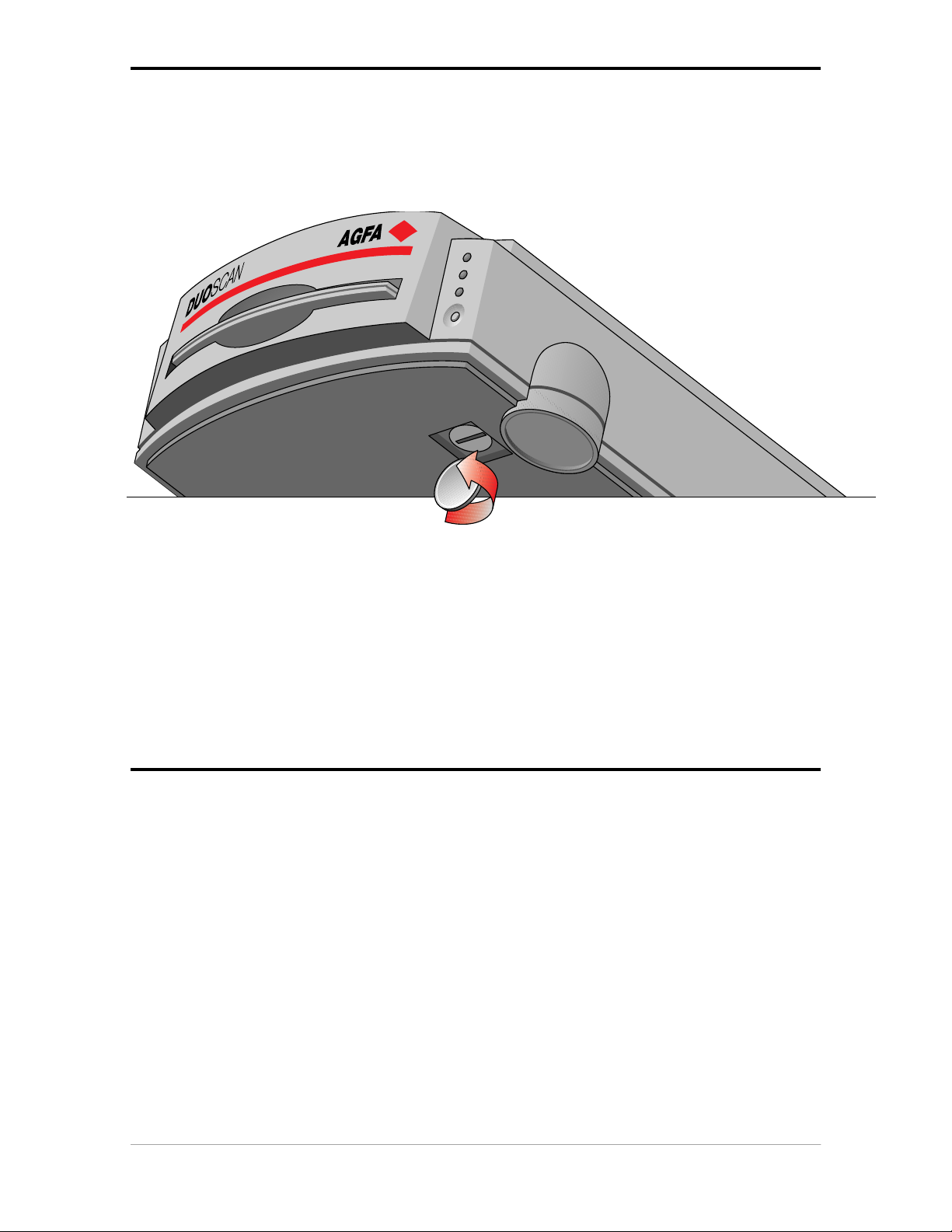
Unlocking the scanner
The scanner’s optical carriage contains all optical components and rides back and forth during the
scan. An unlocking screw holds it in place at the right side of the scanner during shipment. You must
remove this screw before powering up the scanner.
1. Pull the scanner forwards on the edge of the table until you can see the unlocking screw on
the bottom of the scanner.
2. Take a coin and turn the screw a quarter counterclockwise.
The screw comes loose: your scanner is unlocked.
3. Move the scanner back on your desktop. Allow a minimum of 10 cm (4 inches) around each
side of the scanner and a minimum of 15 cm (6 inches) at the rear side of the scanner.
Relocking the scanner
If you need to transport the scanner, you should relock your it. This will protect the scanner's optical
assembly from possible damage.
1. Switch your scanner on.
2. Pull the scanner forwards on the edge of the table until you can see the unlocking screw on
the bottom of the scanner.
3. Take a coin and turn the screw a quarter clockwise.
The screw is fastened: your scanner is locked.
4. Move the scanner back on your desktop.
5. Turn your scanner off.
Chapter 1 — Preparing the scanner 6
Page 7
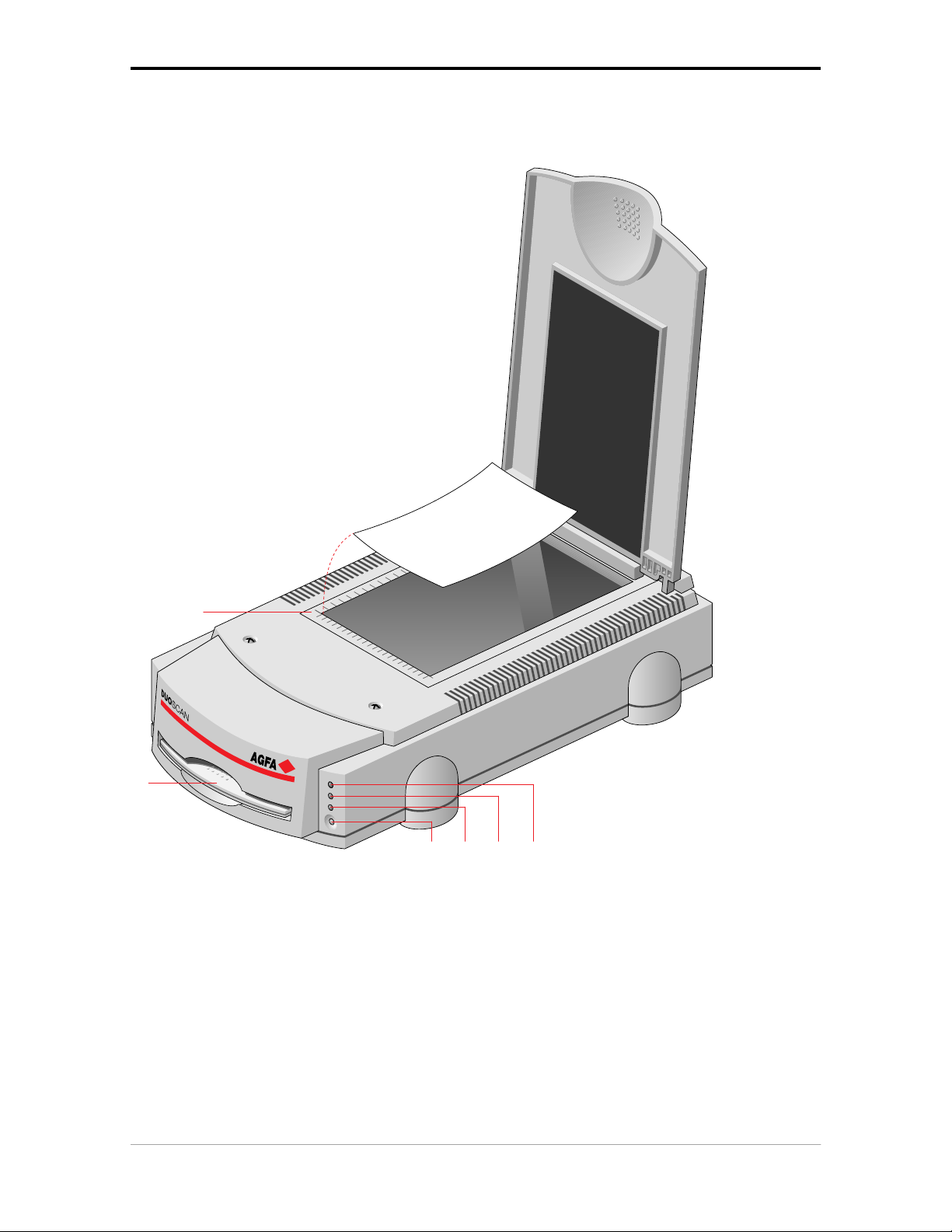
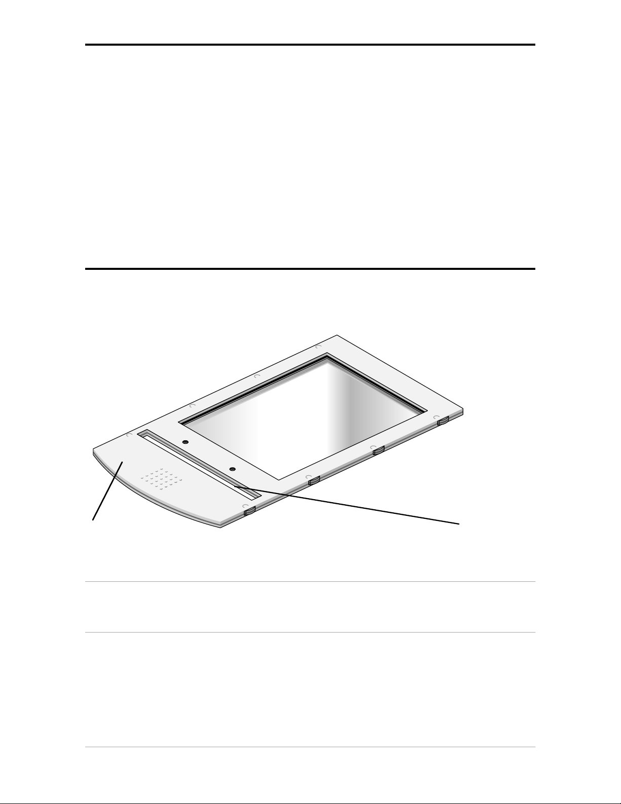
Taking a closer look
Now that you have the scanner out of the box, take a closer look so that you become familiar with its
parts. The figure “front view” illustrates the locations of the different parts of your DuoScan.
2
8
3
1. reflective glass plate
2. adjustable document cover
3. transparency tray
4. power switch
5. reflective ready indicator
6. transparency ready indicator
1
4576
7. power indicator
8. rulers
Chapter 1 — Preparing the scanner 7
Page 8
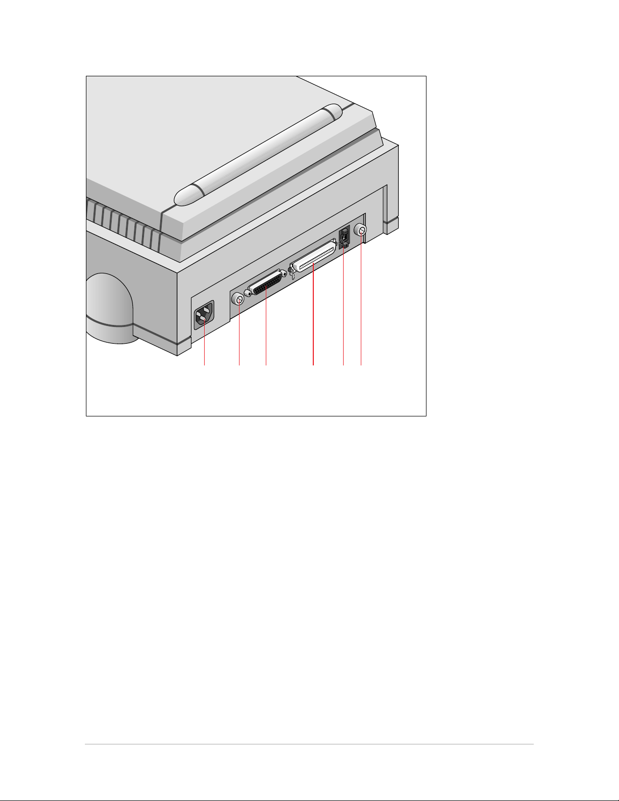
The figure “rear view” illustrates the location of the different parts at the rear of your scanner.
1. power input
2. thumb wheel (to pull out the main board)
3. 25-pin connector
4. 50-pin connector
5. SCSI ID switch
51 23 4 2
Chapter 1 — Preparing the scanner 8
Page 9
1
2
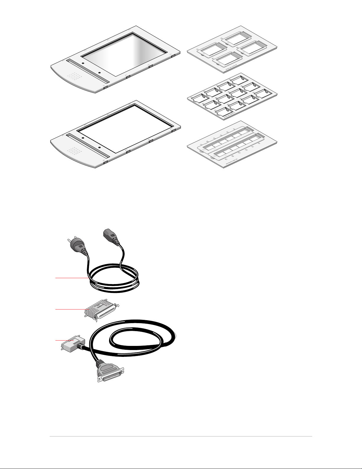
1. universal glass frame
2. batch slide holder frame
3. batch slide holders (3x)
3
1
2
3
1. power cable
2. terminator
3. SCSI cable
Chapter 1 — Preparing the scanner 9
Page 10
Placing reflective originals
You can place a reflective original directly on the scanner’s reflective glass plate. A new feature of
your DuoScan is the adjustable document cover: when you put a thicker original (like a book or a
magazine) on the reflective glass plate, the document cover adapts itself to its thickness.
1. Open the document cover of the scanner.
2. Place the original face down on the reflective glass plate, with its top side against the middle of
the front ruler.
The optical performance of a CCD scanner is always best near the middle of the scan area.
However, for the most common resolutions used for reflective originals, placing originals to the
side will not decrease quality.
3. Close the document cover of the scanner.
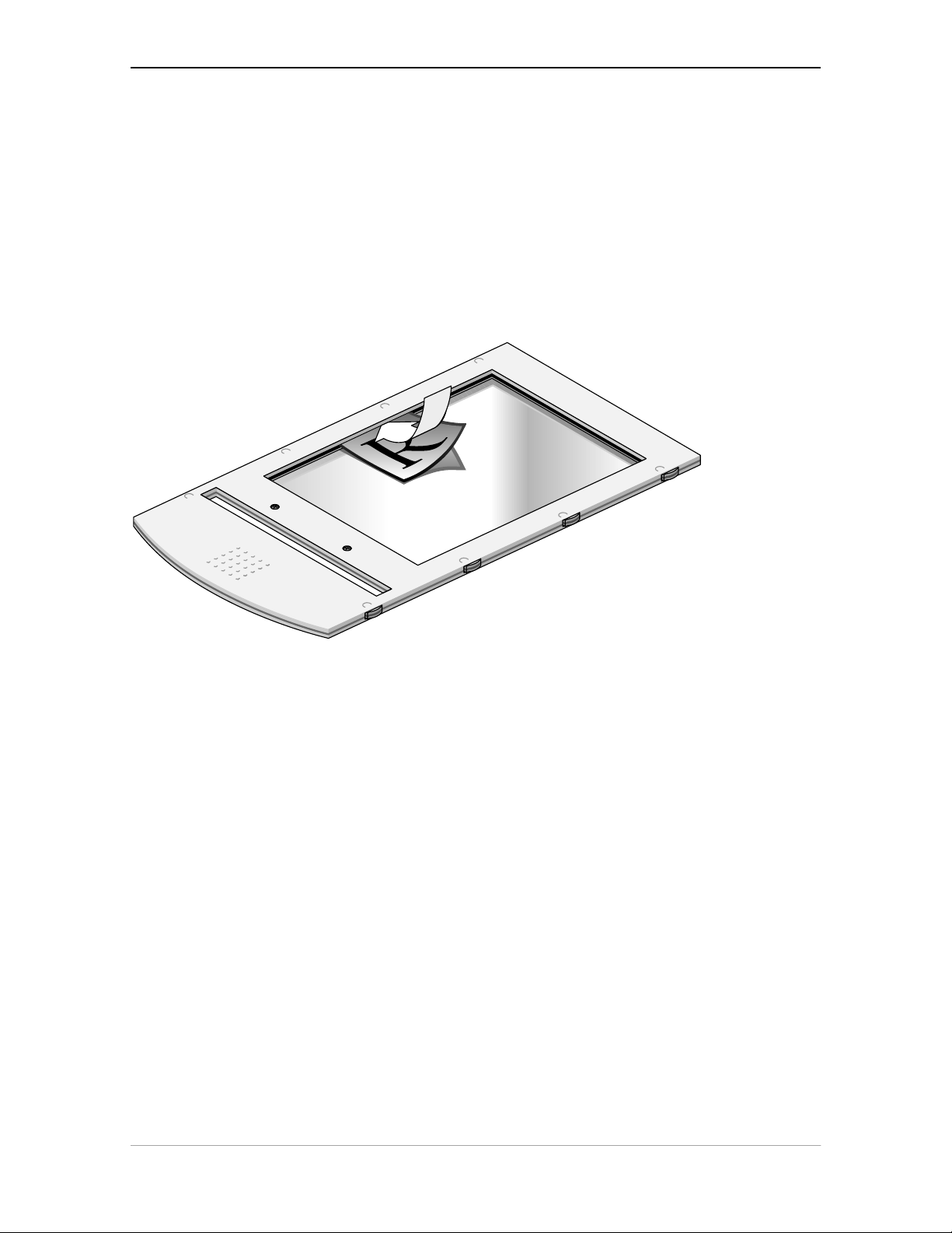
Placing transparent originals
When you scan transparent originals, you use either a batch slide holder frame or the universal glass
frame.
1 2
1. universal glass frame
2. calibration slit
Caution: You always have to attach your transparent originals to the slide holder frame either with the clips of
the universal slide holder, or by using a batch slide holder, or with adhesive tape, even if your transparent
originals are fixed in a regular slide holder. Otherwise you might loose them in the scanner.
Chapter 1 — Preparing the scanner 10
Page 11
Using the universal glass frame
To scan a transparent original, carry out the following instructions:
1. Center the original on the universal slide holder so that its top side is directed towards the
calibration slit of the slide holder frame when you put the universal slide holder on the slide
holder frame of the scanner. This position guarantees the best quality.
2. Clip your original underneath the edge of the universal slide holder.
3. Put the slide holder frame into the transparency tray with the Agfa logo at the upper side.
❖ Note: Make sure that the calibration slit of the slide holder frame is at the front side (standing in
front of the scanner) and that it is clean.
Chapter 1 — Preparing the scanner 11
Page 12
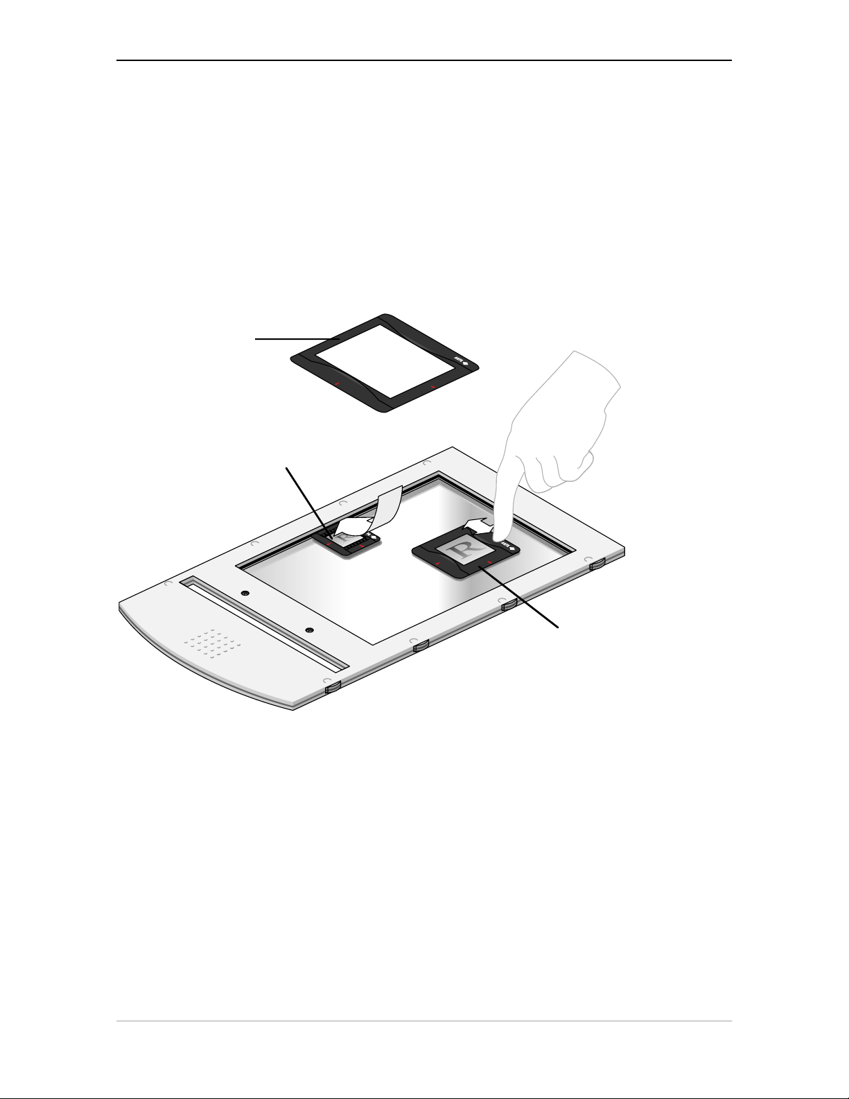
Using the regular slide holders
You can also put your originals in a regular slide holder to avoid blooming and newton rings. There
are three types of regular slide holders: 35 mm strip, 6 x 6 cm, and 4 x 5 inch. To scan a transparent
original using a regular slide holder, carry out the following instructions:
1. Put your original in a regular slide holder.
2. Center the original on the universal glass frame so that its top side is directed towards the
calibration slit of the slide holder frame. This position guarantees the best quality.
3. Fix the regular slide holder on the universal glass frame by pushing it firmly down, the rear of
the holder having a glass adhesive, thereby securing it to the glass. The holder can still be
removed easily,
4. Put the universal glass frame into the transparency tray with the Agfa logo facing upwards.
3
1
2
1. 35 mm regular slide holder
2. 6 x 6 cm regular slide holder
3. 4 x 5 inch regular slide holder
The specifications (resolution,...) of the scanner apply to the whole scan area. However, image
quality is always at its optimum in the middle of the scan area.
Chapter 1 — Preparing the scanner 12
Page 13

Using batch slide holders
There are three different kinds of batch slide holder that can be used in conjunction with the batch
slide holder frame to increase the productivity of the scanner.
35 mm framed slide holder
This frame can hold a maximum of twelve premounted slides at any one time, once loaded it is
mounted into the batch slide holder frame.
Mount a slide into the frame
1. Locate the edge of the slide into the indented “v” on the arm of the holder
2. Push the slide down into the aperture
3. Ensure that the slide is secured by the six fixing lugs on the inside of the frame
The slide position might need slight adjustment after location
4. When all the slides have been mounted locate the batch slide holder into the batch slide holder
frame.
Remove a slide from the frame
1. Remove the batch slide holder from the batch slide holder frame
2. Push the slide gently from underneath, releasing the grip of the mounting lugs.
3. Pull away from the locating “v”.
Chapter 1 — Preparing the scanner 13
Page 14

Chapter 1 — Preparing the scanner 14
Page 15

35 mm strip slide holder
Two strips of five slides can be mounted into the holder which is then mounted into the batch slide
holder frame.
Mount a slide into the frame
1. Unlock the strip slide frame by placing your thumb on the raised points on the end of the holder
and pushing the strip slide frame towards the hinge slot. The frame will become loose.
2. Lift the strip slide frame
3. Place the strip of slides into the centre of the frame
4. Close the frame
5. Lock the frame in position by sliding away from the hinge slot
The position of the slides can be readjusted slightly by moving the slides within the holder
Remove a slide from the frame
1. Unlock the strip slide frame
2. Lift the strip slide frame
3. Remove the slide strip
Chapter 1 — Preparing the scanner 15
Page 16

Chapter 1 — Preparing the scanner 16
Page 17

6 x 9 cm slide holder
This frame holder can hold a maximum of four premounted slides at any one time, once loaded it is
mounted into the batch slide holder frame.
Mount a slide into the frame
1. Unlock the frame by placing your thumb on the raised points on the end of the holder and
pushing the frame towards the hinge slot. The frame will become loose.
2. Lift the frame
3. Locate the slide against the front edge of the holder
4. Close the frame
5. Lock the frame in position by sliding it away from the hinge slot
Remove a slide from the frame
1. Unlock the frame by placing your thumb on the raised points on the end of the holder and
pushing the frame towards the hinge slot. The frame will become loose.
2. Lift the frame
3. Remove the slide
4. Close the frame
Chapter 1 — Preparing the scanner 17
Page 18

Chapter 1 — Preparing the scanner 18
Page 19

Performing a power-on test
You are now ready to perform a power-on test to check if the scanner is operating correctly.
1. Check whether you have unlocked the scanner.
2. Connect the power cable to the scanner.
Make sure that you are using the correct power cable for the voltage in your area. Double-
check whether the voltage indicated on the back panel of the scanner corresponds with the
voltage in your area. If not, call your dealer or Agfa service representative.
3. Switch on the scanner.
The scanner performs a self-test during which the power indicator light (green) switches on and
the reflective ready indicator light (yellow) and the transparency ready indicator light (yellow)
remain blinking. This takes about half a minute. After the self-test, the three lights switch on.
If a malfunction is detected during the self-test, that is, if the ready indicators remain blinking or
go off, refer to Appendix A, ‘Troubleshooting’.
4. Switch off the scanner.
Chapter 1 — Preparing the scanner 19
Page 20

Chapter 2 — Installing the scanner
This chapter shows you how to set up your DuoScan with your Apple Macintosh or PC. You’ll find
information about:
Minimum Hardware requirements and recommendations
Environmental requirements
Precautions
Cleaning your scanner
SCSI devices
Installation for the Apple Macintosh
Choosing a SCSI ID number
Connecting the scanner
Testing the connection
Installation for the PC
Which SCSI interface card
Choosing a SCSI ID number
Connecting the scanner
Testing the connection
Minimum hardware requirements and recommendations
■ For the Apple Macintosh:
■ A Power PC processor.
■ A 13 inch color monitor (24 bit color display recommended).
■ 16 MB of RAM.
■ A high-capacity disk drive.
■ The amount of disk space available on your Macintosh determines the number and size of
the images you can scan. Make sure you have enough free storage space on your hard
disk. You need about two times the size of the image to scan, edit and save an image. You
need a minimum of 30 MB free hard disk space and 8 MB of RAM for color images.
■ System 7.0 operating system or higher.
Chapter 2 — Installing the scanner 20
Page 21

■ For the PC:
■ A 486 processor.
■ A 13 inch color monitor (24 bit color display recommended).
■ 16 MB of RAM.
■ A high-capacity disk drive.
■ A SCSI (Small Computer System Interface) interface card supported by FotoLook for
connecting your scanner. In general, FotoLook supports all fully WINASPI compatible
cards. Some SCSI cards require a special SCSI cable. Contact your supplier for the proper
cable. A regular SCSI cable is included in the packaging.
You should review your PC's documentation with respect to installing SCSI interface
cards. Check the installation and setup guidelines in the documentation that is supplied
together with your SCSI interface card.
■ The amount of disk space available on your PC determines the number and size of the
images you can scan. Make sure you have enough free storage space on your hard disk.
You need about two times the size of the image to scan, edit and save an image. You
need a minimum of 30 MB free hard disk space and 8 MB of RAM for color images.
■ An IBM PC or compatible capable of running MS Windows, Windows 95 or Windows NT.
Environmental requirements
■ Place the scanner on a horizontal, flat surface.
■ To ensure proper ventilation, allow a minimum of 10 cm (4 inches) free space around each side
of the scanner and a minimum of 15 cm (6 inches) at the rear of the scanner.
■ Make sure that no vibrations or shocks occur.
■ Make sure that the area is free of excessive dust.
■ Avoid any contact with water.
■ The scanner is designed to operate optimally when the environmental temperature is between
10 °C and 40 °C. Avoid exposure to direct sunlight and heating devices.
■ The scanner is designed to operate optimally when the environmental humidity is between
10 % and 85 %. Avoid environments where humidity fluctuations might occur.
■ Check whether the voltage of the power cable corresponds to the voltage in your area. If not,
contact your dealer or Agfa service representative.
Chapter 2 — Installing the scanner 21
Page 22

Precautions
For your own safety and that of your equipment, respect conscientiously the environmental
requirements (see the above section) and always take the following precautions:
Caution: For the reason of safety, besides the personal maintenance mentioned in this owner's guide, don’t
try to remove any mechanical parts or any electronic devices. If your scanner needs servicing, our dealer and
service offices are available to help you.
■ Handle your DuoScan with care: its glass plates are fragile. There is no warranty on breaking the
glass plates and your dealer is not liable for the consequential damages.
■ Frequently check that there is no overheating of the power plug and that the power plug is
pushed all the way into the socket.
■ Switch the machine off at the end of your working day or during power failure.
■ Disconnect the power plug when you want to clean the reflective glass plate and when the
scanner needs servicing.
■ Do not open the scanner housing as it contains high voltage areas and sensitive components.
Any corrective maintenance should be carried out by your dealer or Agfa service
representative.
■ Do not leave originals on the reflective glass plate or on the slide holder frame for excessive
periods of time. The warmth of the scanner may cause them to deteriorate.
■ Make sure that the originals are properly attached on the glass plate, otherwise you might loose
them in the scanner.
■ To avoid crashes, never use extension cables for SCSI cables.
■ For safety reasons, never use extension cables for power cables.
Cleaning your scanner
■ In order to maintain the quality of your scanned images, regularly clean both glass plates (the
reflective glass plate and the universal glass frame).
■ Before cleaning, switch off the power to the scanner and unplug the cable.
■ Use a damp cloth and a mild detergent or alcohol to clean the surface of the glass plate.
■ When you use sprays directly onto the glass plate, avoid the seams around the glass, as this
may cause the liquid to penetrate and contaminate the mirrors and lenses inside the scanner.
Do not use detergent on the plastic parts of your scanner.
■ The cleaning of the calibration slit in the transparency holder frame is especially important.
Keep this area dust- and dirt-free.
Chapter 2 — Installing the scanner 22
Page 23

SCSI devices
DuoScan is a Small Computer System Interface (SCSI) device. It communicates with your computer
by using the SCSI-2 standard. The SCSI communication standard allows you to have up to seven
peripheral devices connected to your computer.
Before connecting the SCSI devices you should always make sure that your computer and all SCSI
devices are switched off. If either the computer or any of the devices remains on, you could damage
the computer or the device.
A unique SCSI ID number is assigned to each device in the SCSI chain enabling your computer to
identify the device it wants to communicate with and the priority of each device.
Caution: If two SCSI devices have the same ID number, your system will not work properly and you may
damage your SCSI devices.
To avoid crashes, never use extension cables for SCSI cables.
Installation for the Apple Macintosh
This section shows you how to set up your DuoScan with your Macintosh computer. You must first
choose and set a SCSI ID number, then connect the scanner to your Macintosh, and finally test the
connection.
Choosing a SCSI ID number
Connecting the scanner
Testing the connection
Chapter 2 — Installing the scanner 23
Page 24

Choosing a SCSI ID number
Before you connect your DuoScan to your Macintosh, you have to find out which SCSI ID numbers
are already assigned and which numbers are free. To do this, you can use the utility
‘SCSI ID Checker’. You will find this utility in the FotoLook folder after you installed the software.
1. Copy the SCSI ID Checker to your Macintosh computer if not already done.
2. Open the SCSI ID Checker.
A dialog box appears with a list of the SCSI ID numbers that are free in your Macintosh
computer.
Your Macintosh always occupies ID 7, its internal hard disk usually occupies ID 0 or ID 1 and CD
ROM usually occupies ID 3. If your Macintosh is equipped with 2 SCSI-busses, the button Next
Bus allows you to switch busses.
3. Check if SCSI ID number 2 is free.
Your DuoScan is preset to ID 2.
Chapter 2 — Installing the scanner 24
Page 25

■ If SCSI ID number 2 is free, go to instruction 5.
n
n
n
■ If SCSI ID number 2 is already assigned, you need to set the scanner to a free SCSI ID number.
Make sure your scanner is switched off and is disconnected from your computer.
Decide on an unassigned SCSI ID number.
Use the SCSI ID switch (see figure) at the rear of the scanner to set the desired SCSI ID.
Push above the SCSI ID number to decrease the number, push underneath the SCSI ID
number to increase the number.
5. Click OK to close the SCSI ID Checker.
Chapter 2 — Installing the scanner 25
Page 26

Connecting the scanner
Before you connect the scanner to your Macintosh, make sure that your scanner as well as your
Macintosh and everything connected to it are switched off.
A terminator and a SCSI cable are supplied with your scanner. Apple Computer, Inc. recommends
using only its proprietary (Black) terminator for the Macintosh IIfx.
Caution: For safety reasons, never use extension cables for power cables.
Always make sure there are no more than two terminators in your SCSI chain, one at the beginning and one at
the end. Some SCSI devices have built-in terminators and must therefore be placed at the beginning or end of
your SCSI chain. Please check the documentation of each of your SCSI devices if you're not sure whether the
device has a built-in terminator. Your DuoScan has no built-in terminator.
If your DuoScan is the only SCSI device to be connected to your Apple Macintosh:
1. Place the terminator on the 50-pin connector of the scanner.
2. Connect the smaller 25-pin end of the SCSI cable to the connector of your Apple Macintosh.
3. Connect the larger 50-pin end of the SCSI cable to the free side of the terminator.
4. Snap the diamond shaped wire clips into the clip brackets to secure the connection.
Chapter 2 — Installing the scanner 26
Page 27

If your DuoScan will be connected to your Apple Macintosh together with other SCSI devices:
■ If you install the scanner at the end of your SCSI chain:
1. Remove the terminator from the last device in the SCSI chain.
2. Connect the 50-pin end of the SCSI cable to the connector that has become available on this
device.
3. Place the terminator on the free 50-pin connector of the scanner.
4. Connect the 25-pin end of the SCSI cable to the free connector of the scanner.
5. Snap the diamond shaped wire clips into the clip brackets to secure the connection.
Chapter 2 — Installing the scanner 27
Page 28

■ If you install the scanner between two other SCSI devices:
1. Disconnect your SCSI cable from one of these two SCSI devices.
2. Connect the free end of this SCSI cable to the scanner.
3. Connect the 50-pin end of the SCSI cable (the one supplied with your scanner) to the other
adjacent SCSI device.
4. Connect the 25-pin end of the SCSI cable (the one supplied with your scanner) to the scanner.
5. Snap the diamond shaped wire clips into the clip brackets to secure the connection.
Chapter 2 — Installing the scanner 28
Page 29

Testing the connection
You are now ready to perform a test to check if the scanner is correctly connected to your Macintosh.
Caution: Check if the scanner is properly unlocked.
1. Connect the power cable to the scanner.
Make sure that you are using the correct power cable for the voltage in your area.
2. Check if the SCSI cable is properly connected.
3. Switch the scanner on.
The scanner performs a self-test: the power indicator light switches on and the two other
indicator lights start blinking. After the self-test all the scanner’s indicator lights switch on.
4. Switch on any other SCSI devices you may have attached, and wait for them to start up.
5. Switch on your Macintosh.
As it starts up, your Macintosh performs a series of tests to verify the correct system
configuration.
6. Open the SCSI ID checker.
7. Verify whether the Macintosh sees the scanner at its proper SCSI address.
In case of problems, refer to Appendix A, ‘Troubleshooting’ .
8. Close the SCSI ID checker.
9. Install the FotoLook software following the instructions on the CD-ROM leaflet.
Chapter 2 — Installing the scanner 29
Page 30

Installation for the PC
This section shows you how to set up your DuoScan with your PC. You can find information on
which SCSI interface card to use, instructions for connecting the scanner to your PC and
instructions for testing the connection.
Which SCSI interface card
Choosing a SCSI ID number
Connecting the scanner
Testing the connection
Which SCSI interface card
DuoScan requires a SCSI interface card to work with your PC or compatible computer. If your PC
does not have such a card or built-in interface, contact your dealer or Agfa service representative.
The scanner software supplied with DuoScan supports ASPI-compatible SCSI interface cards.
❖ Note: Please check the following documentation:
■ The Read Me file on the PC scanner driver software disk for up-to-date information.
■ The documentation supplied with your interface card. This will tell you how to install the
card.
■ If you are using third party software, check the documentation supplied with that software
for the SCSI interface cards supported.
Choosing a SCSI ID number
Before you connect your DuoScan to your PC, you have to find out which SCSI ID numbers are
already assigned and which numbers are free. To do this, you can use the Windows utility ‘Show
SCSI’. You will find this utility in the software of Windows 95 or in the software of your SCSI interface
card (SCSI Interrogator).
1. Open 'Show SCSI'.
A dialog box appears with a list of the SCSI ID numbers that are free in your PC.
Your PC always occupies ID 7. If your PC is equipped with 2 SCSI-busses, the button Next Bus
allows you to switch busses.
2. Check if SCSI ID number 2 is free.
Your DuoScan is preset to ID 2.
Chapter 2 — Installing the scanner 30
Page 31

■ If SCSI ID number 2 is free, go to instruction 4.
n
n
n
■ If SCSI ID number 2 is already assigned, you need to set the scanner to a free SCSI ID number.
Make sure your scanner is switched off and is disconnected from your computer.
Decide on an unassigned SCSI ID number.
Use the SCSI ID switch at the rear of the scanner to set the desired SCSI ID.
Push above the SCSI ID number to decrease the number, push underneath the SCSI ID
number to increase the number.
4. Close 'Show SCSI'.
Chapter 2 — Installing the scanner 31
Page 32

Connecting the scanner
Before you connect the scanner to your PC, make sure that your scanner as well as your PC and
everything connected to it are switched off.
A terminator and a SCSI cable are supplied with your scanner.
Caution: For safety reasons, never use extension cables for power cables.
Always make sure there are no more than two terminators in your SCSI chain, one at the beginning and one at
the end. Some SCSI devices have built-in terminators and must therefore be placed at the beginning or end of
your SCSI chain. Please check the documentation of each of your SCSI devices if you're not sure whether the
device has a built-in terminator. Your DuoScan has no built-in terminator.
Never try to connect the scanner to the serial or parallel port of your PC: you might seriously damage your
equipment if you do.
■ If your PC has a high density connector, you might need to buy a special cable from your
dealer.
■ If your PC has a 25-pin connector, follow the instructions of
'Installation for the Apple Macintosh': 'Connecting the scanner' .
■ If your PC has a 50-pin connector and your DuoScan is the only SCSI device to be connected
to your PC:
Chapter 2 — Installing the scanner 32
Page 33

1. Set the scanner to an unused SCSI ID number between 1 and 6.
n
For more information, see ‘Choosing a SCSI ID number’ earlier in this chapter.
2. Connect the larger 50-pin end of the SCSI cable to the connector at the rear of your PC.
Use the SCSI cable supplied with the scanner.
3. Place the terminator at the 50-pin connector of the scanner. Snap the diamond shaped wire
clips into the clip brackets to secure the connection.
4. Connect the smaller 25-pin end of the SCSI cable to the free connector of the scanner.
■ If your PC has a 50-pin connector and your DuoScan will be connected to your PC together
with other SCSI devices:
If you install the scanner at the end of your SCSI chain:
1. Set the scanner to an unused SCSI ID number between 1 and 6.
For more information, see ‘ Choosing a SCSI ID number’ earlier in this chapter.
2. Connect the 50-pin end of the SCSI cable to the connector at the rear of your device.
Use the cable supplied with the scanner.
3. Place the terminator on the 50-pin connector of the scanner. Snap the diamond shaped wire
clips into the clip brackets to secure the connection.
4. Connect the 25-pin end of the SCSI cable to the scanner.
Chapter 2 — Installing the scanner 33
Page 34

n
If you install the scanner between two other devices:
1. Disconnect the two devices between which you want to install the scanner.
2. Set the scanner to an unused SCSI ID number between 1 and 6.
For more information, see ‘Choosing a SCSI ID number’ earlier in this chapter.
3. Connect the 50-pin end of the SCSI cable to the connector at the rear of the adjacent device.
Use the cable supplied with the scanner.
4. Connect the 25-pin end of the cable to the scanner's 25-pin connector.
5. Connect the scanner to the next device in the SCSI chain.
6. Make sure that the last device in the chain is terminated.
Caution: In this configuration you are not allowed to put the terminator on the scanner.
In case of problems, refer to Appendix A, ‘Troubleshooting’ .
Chapter 2 — Installing the scanner 34
Page 35

Testing the connection
You are now ready to perform a test to check if the scanner is correctly connected to your PC.
Caution: Check if the scanner is properly unlocked.
1. Connect the power cable to the scanner.
Make sure that you are using the correct power cable for the voltage in your area.
2. Check if the SCSI cable is properly connected.
3. Switch the scanner on.
The scanner performs a self-test: the power indicator light (green) switches on and the ready
indicator lights (yellow) start blinking. After the self-test the scanner’s power indicator light
switches on.
4. Switch on any other SCSI devices you may have attached, and wait for them to start up.
5. Switch on your PC.
6. Check in 'Show SCSI' if the SCSI interface card sees the scanner at the right address.
7. Install the FotoLook software following the instructions on the CD-ROM leaflet.
Chapter 2 — Installing the scanner 35
Page 36

Appendix A — Troubleshooting
This appendix explains some common problems you may come across when starting up or using
your DuoScan.
The power indicator fails to light up.
■ Verify the power connection to the scanner.
■ Check if the power switch is turned on.
■ If you have confirmed that there is power to the scanner it is likely that the scanner fuse
needs to be replaced. Contact your dealer.
The power indicator lights up but nothing happens.
■ Contact your dealer or Agfa service representative.
The scanner makes a banging noise and nothing moves under the glass plate.
■ The scanner was not properly unlocked. Immediately switch the scanner off and unlock
properly, or call your service representative.
The ready indicator light (yellow) on the scanner’s operating panel remains
blinking or goes off after the power-up sequence (= about half a minute).
A malfunction has been detected by the scanner.
■ Check if you have unlocked the scanner. If this can not be the problem please contact
your dealer or Agfa service representative.
The power indicator fails to light up.
■ Verify the power connection to the scanner.
■ Check if the power switch is turned on.
■ If you have confirmed that there is power to the scanner it is likely that the scanner fuse
needs to be replaced. Contact your dealer.
The workstation does not start up. If your workstation is an Apple Macintosh a
little floppy disk with a question mark appears on your screen.
Your workstation cannot find its hard disk due to a conflict with the SCSI ID numbers of the
devices you have attached.
■ Disconnect all SCSI devices (except the start-up disk) and connect them one by one,
beginning with the scanner, to identify the device that causes the problem (switch all
devices off before breaking or making connections).
Appendix A — Troubleshooting 36
Page 37

The scanner software cannot find the scanner
After opening the Scan dialog box, a message appears telling that no scanner is connected,
although the scanner is connected.
■ Check the Installation procedure, to see if you followed the instructions. Pay special
attention to the setting of the SCSI ID number: check the SCSI ID Checker.
■ Maybe you did not wait long enough for all SCSI devices to start up, before you switched
your workstation on. Therefore, try restarting your workstation. If this doesn’t help,
■ Disconnect all SCSI devices and connect them one by one, beginning with the scanner,
to identify the device that causes the problem.
The scanner reports errors during scanning (Apple Macintosh)
■ Check the presence of the SCSI terminator. If this can not be the problem, please contact
your dealer or Agfa service representative.
When starting up, the scanner makes a beeping noise and all the lights are
blinking.
■ This indicates a SCSI cabling problem. Be sure to immediately shut down all machines in
the chain and then solve the problem. (Missing terminator? Bad cable? Internally
terminated component in chain?)
Appendix A — Troubleshooting 37
Page 38

Appendix B — Technical information
This appendix provides some technical information about your DuoScan. Technical specifications
are subject to change without notice.
Scanner type: Flatbed legal or A4 size color CCD scanner
CCD: 8000 elements, color type
Optical resolution: 2000 dpi vertical x 1000 dpi horizontal
Output resolution: 20 - 4000 ppi
A/D Conversion: 36 bit (12 bit per color)
Output pixel depth: 1 bit output for line-art (black and white)
8 or 12 bit output for gray
24 or 36 bit output for color
Density range: 3.2 D
Max. density detected: 3.4 D
Scanning speed: 7-14 ms/line
Original sizes: A4 or Legal
Maximum scan area: Maximum reflection:
8 x 14 inch (203 x 355 mm)
Maximum transmission:
8 x 10 inch (203 x 254 mm transparency)
Memory: 1 Mb RAM
Reflection scanner lamp: 2 x cold cathode
6000 hr lifetime
Transparency lamp: Cold cathode
6000 hr lifetime
Warm up time: approximately 35 seconds
180 seconds to reach final image quality
Appendix B — Technical Information 38
Page 39

Power supply: 100 V to 240 V, 47 - 63 Hz
Power consumption: 40 W
Dimensions: 400 mm (16 inch) x 182 mm (7 inch) x 613 mm
(24 inch) (W x H x L)
Weight: 13,5 kg
Acoustic noise: max. 55 dB in worst condition
Interface: SCSI-2 interface
Maximum throughput 4 MB / sec
Environment: Operating temperature:
10 °C to 40 °C (50 °F to 104 °F)
Relative humidity:
10 % to 85 %
Appendix B — Technical Information 39
Page 40

Appendix C — DuoScan regulation compliance
Safety regulations
Electromagnetic interference
Safety regulations
DuoScan has been designed to comply with:
■ VDE 805
■ IEC 950, EN 60950 (GS approved)
■ UL 1950-D3
■ CSA c22.2 No. 950-M89
DuoScan also complies with CE regulations and carries the CE mark.
UL Safety Statement
Instructions for power supply cord selection:
Use a UL listed, Type SVT or SJT cord, three conductor, rated 10 A 125 V, not exceeding 15ft in
length.
FTZ: Bescheinigung des Herstellers/Importeurs
Hiermit wird bescheinigt dass der Image Scanner in Übereinstimmung mit den Bestimmungen der
vgf 1046/1984 funk-entstört ist.
Der Deutschen Bundespost wurde das inverkehrbringen dieses Gerätes angezeigt und
Berechtigung zur Überprüfung der Serie auf Einhaltung der Bestimmungen eingeraumt.
TÜV: Wichtige Sicherheitshinweise
1. Bitte Lesen Sie sich diese Hinweise sorgfältig durch.
2. Um eine Beschädigung des Gerätes zu vermeiden sollten Sie nur Zuberhörteile verwenden,
die vom Hersteller zugelassen sind.
3. Das Gerät ist vor Feuchtigkeit zu schützen.
4. Bei der Aufstellung des Gerätes ist auf sicheren Stand zu achten. Ein Kippen oder Fallen
könnte Verletzungen hervorrufen. Verwenden Sie nur sichere Standorte und beachten Sie
die Aufstellhinweise des Herstellers.
5. Die Belüftungsöffnungen dienen zur Luftzirkulation die das Gerät vor Überhitzung schütz.
Sorgen Sie dafür, daß diese Öffnungen nicht abgedeckt werden.
6. Die Netzanschulßsteckdose muß aus Gründen der elektrischen Sicherheit einen
Schutzleiterkontakt haben.
7. Durch die Lüftungsöffnungen dürfen niemals Gegenstände oder Flüssigkeiten in das Gerät
gelangen. Dies könnte einen Brand bzw. elektrischen Schlag auslösen.
Appendix C — DuoScan regulation compliance 40
Page 41

8. Öffnen Sie niemals das Gerät. Das Gerät darf aus Gründen der elektrischen Sicherheit nur von
authorisiertem Servicepersonal geöffnet werden.
9. Die Steck dose sollte nahe dem Gerät und leicht zugänglich sein.
Electromagnetic interference
DuoScan is designed to comply with:
■ VDE 0871, class B
■ VDE 0875, level N
■ FCC 20718, part 15, subpart B, class B
Federal Communications Commission Radio Frequency Interference
Statement.
Note: This equipment has been tested and found to comply with the limits for a Class B digital
device, pursuant to Part 15 of the FCC Rules. These limits are designed to provide reasonable
protection against harmful interference when the equipment is operated in a residential installation.
This equipment generates, uses, and can radiate radio frequency energy and if not installed and
used in accordance with the instruction manual may cause harmful interference to radio
communications. However, there is no guarantee that interference will not occur in a particular
installation. If this equipment does cause harmful interference to radio or television reception, which
can be determined by turning the equipment off and on, the user is encouraged to try to correct the
interference by one or more of the following measures:
■ Reorient or relocate the receiving antenna.
■ Increase the separation between the equipment and receiver.
■ Connect the equipment into an outlet on a circuit different from that to which the receiver is
connected.
■ Consult the dealer or an experienced radio TV technician for help.
Notice:
(1) The changes or modifications not expressly approved by the party responsible for compliance
could void the user’s authority to operate the equipment.
(2) Shielded interface cables and AC power cord, if any, must be used in order to comply with the
emission limits.
Canadian department of Communications
This digital apparatus does not exceed the Class B limits for radio noise emissions from digital
apparatus set out in the Radio Interference Regulations of the Canadian Department of
Communications.
Le présent appareil numérique n’émet pas de bruits radioélectriques dépassant les limites
applicables aux appareils numériques (de la classe B) prescrites dans le Règlement sur le brouillage
radioélectrique édicté par le ministère des Communications du Canada.
Appendix C — DuoScan regulation compliance 41
 Loading...