

Page 1

DD+DIS053.00E Repair and Service
Troubleshooting
Section 6 - 3
List of contents
1 Troubleshooting: General ...........................................................................1
1.1 Symptom: Printer does not start up properly...................................................... 2
1.2 Symptom: An error message is displayed on the internal or external display.. 3
1.3 Symptom: An error message as text is displayed on the internal display ........ 4
1.3.1 Symptom: "Remove output jam" Film j am or film running askew in the decurl unit . ..4
1.4 Symptom: Drystar 3000 does not print. No error message is displayed........... 8
1.5 Symptoms: Image fault........................................................................................ 10
1.6 Symptom: Hard disk doesn’t work ..................................................................... 20
1.7 Troubleshooting Ethernet failures...................................................................... 20
1.8 What to do if a bus error occurs ?...................................................................... 21
1.8.1 Bus crash caused by COS board...........................................................................22
1.8.2 Spurious Interrupt .................................................................................................. 22
1.8.3 Illegal instruction....................................................................................................22
2 Software Installation / Configuration from Scratch................................. 22
2.1 Software Installation from Scratch..................................................................... 22
2.2 Configuration from Scratch.................................................................................22
Revision 22 Type 5361 Section 6.3 / I
Page 2

DD+DIS053.00E Repair and Service
3
616
3
CDR
Troubleshooting
1 Troubleshooting: General
In case of troubles with the Drystar3000 we can distinguish between different symptoms.
Enclosed a list of typical symptoms that may occur
# Symptom Description Reason Refer to
1 Printer does not start up. Either nothing on the
internal display or "Drystar 3000 initialisation,
please wait" forever (> 5 min.)
AOS shell not booted up
completely
1.1
2 An error message is displayed on the internal or
external display
3 An error message as text is displayed on the
internal display
?
ERROR
Remove
Output Jam
XX.
5
4 Drystar 3000 does not print. No error messag e
is displayed.
5 Image fault: Monitor at console and image
printed at Drystar3000 are different
Problem during printer
operation: Printer SW / HW
problem.
Problem during printer
operation:
A user intervention is
required.
Either the image does not
get to the printer (network)
or printer configur ation
mismatch
Either problem of imag e
processing (Software /
Hardware) or problem of
the host system
1.2
1.3
1.4
1.5
Revision 22 Type 5361 Section 6.3 / 1
Page 3
Repair and Service DD+DIS053.00E
Troubleshooting
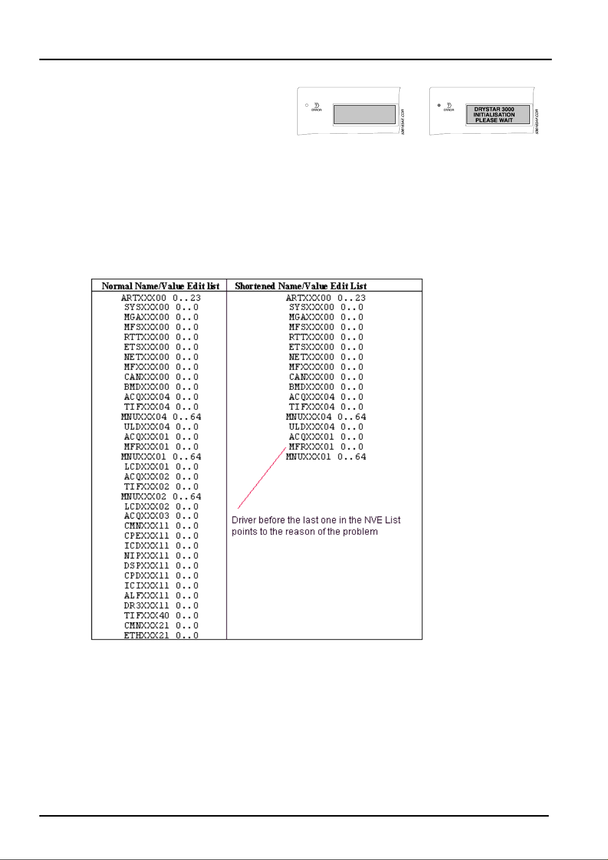
1.1 Symptom: Printer does not start up properly
Either nothing on the internal display or
"Drystar 3000 initialisation, please wait"
forever (> 5 min.)
Reason:
AOS shell not booted up completely
Cure:
• Start IMOS Drystar3000 (If you do not g et access to the Drystar 3000, the hard disk may
be defective. See section: Symptom: Hard disk doesn’t work)
• Enter Menu „Application - Customization - Name/Value Edit“
• Look to the complete list:
• The list of different components stops somewhere before CMNXXX21 (see example)
- In the case of this example, the MFRI driver is the last one that booted up completely. Most
likely the MFRI is not jumpered correctly or a conf iguration mismatch exists.
General Proceeding in such a case: Check whether the VME hardware interfaces are
really installed as shown in the configuration screen. Check jumpersetting of the VME
interface.
In case the problem is originated from SW problems dur ing SW installation or
configuration, a configuration from scratch is recomm ended ( s ee chapt er 2).
Section 6.3 /2 Drystar 3000 (Type 5361) Revision 22
Page 4
DD+DIS053.00E Repair and Service
Troubleshooting
Note: If the NVE list stops with ARTXX X00, the reason is either, that the system is halted
(make a reset in this case) or t hat a VME bus crash occurr ed. See also: „What to do if
a bus crash occurs“.
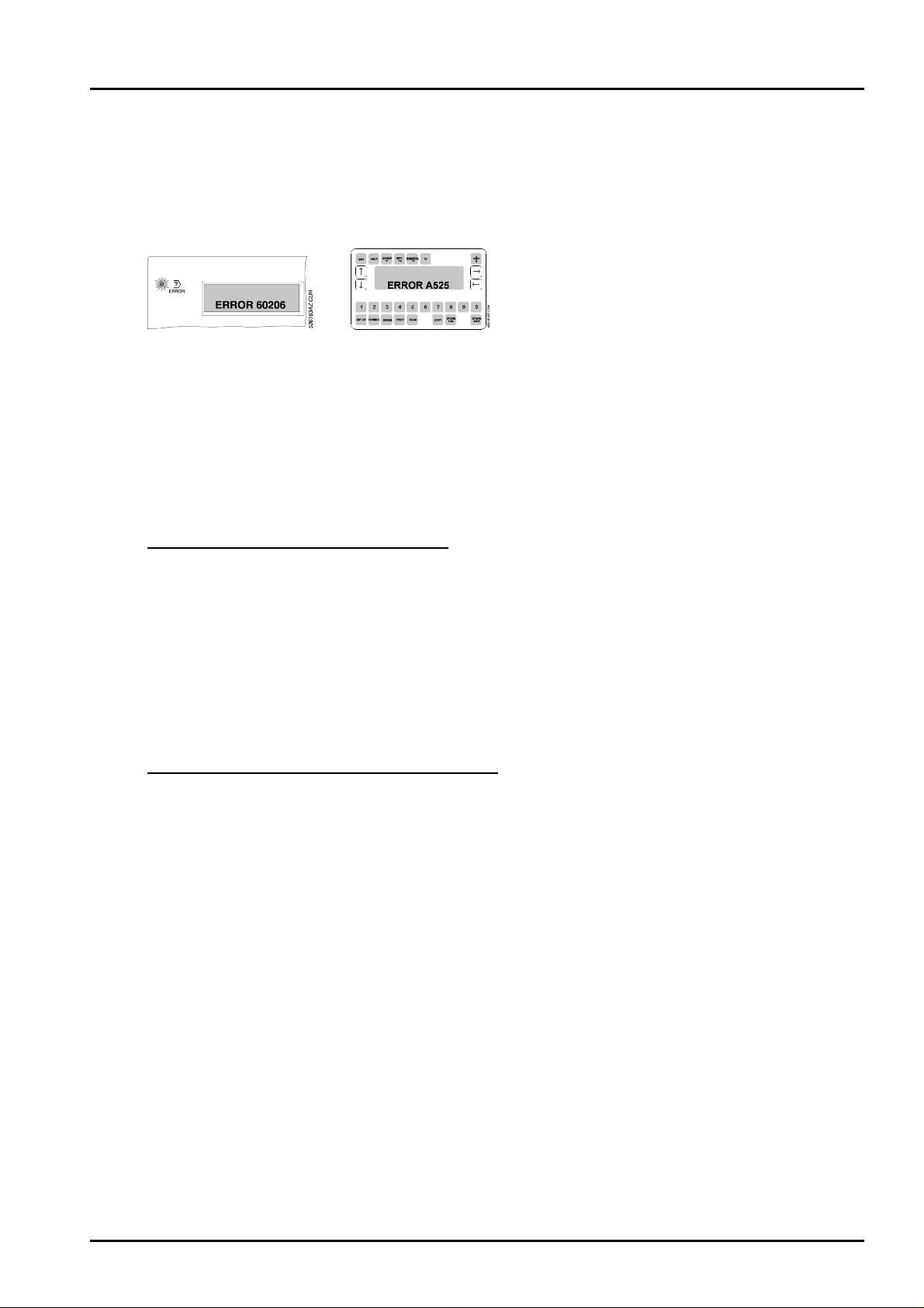
1.2 Symptom: An error message is displayed on the internal or external display
Reason:
Problem during printer operation: Printer SW / HW problem.
Cure:
• Start IMOS Drystar3000
• Select „Repair“ - „Error Messages“ and enter t he fault to get an explanation.
Note: Error messages are always created according to the "father-son" pr inciple. I.e. there is
always a basic error creating another one and so on.
How to see the current error messages:
• They are either displayed on the local keypad or the LCD user keypad. I f errors are
displayed as text, select menu 10 on the local keypad: Print Eng ine - Error Details* to get
an error code.
Additionally, the error messages are log ged in the logbook:
• Select "Logbook" in the main m enu " Repair " in IMOS.
• Select „detailed“ to get the explanation of the errors, too.
Attention: Always look to the error chain. I f it ends with „0000“ the error was repaired
internally.
How to get the explanation to error messages:
• Select „Error messages“ in the IMOS Drystar 3000 main menu „ Repair “ .
Revision 22 Type 5361 Section 6.3 / 3
Page 5
Repair and Service DD+DIS053.00E
3
616
3
CDR
Troubleshooting
1.3 Symptom: An error message as text is displayed on the internal display
?
ERROR
Reason:
Problem during printer operation: A user intervention is required.
Cure:
• First perform t he act ion as r equired on the internal display (e.g. remove f ilm jam)
• Then select menu 10 on the local keypad „Print Eng ine“ - „ Er ror Details“. Two errors will be
displayed.*
• Start IMOS Drystar3000
• Select „Repair“ - „Error Messages“ and enter the two faults to get an explanation. Normally
the first error message points to the problem.*
• In case the problem persists aft er r esetting the device and the following filmrun,
troubleshoot as described in the error explanation.
*only as of Drystar 3000 SW release 1.40 or higher.
Remove
Output Jam
XX.
5
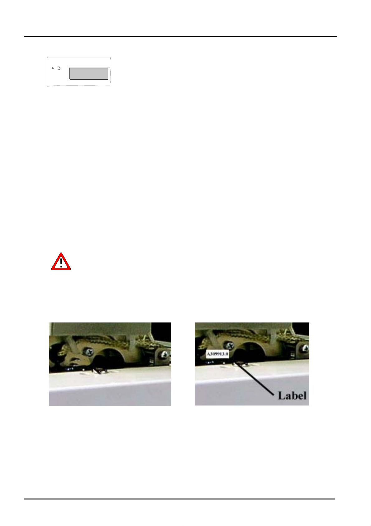
1.3.1 Symptom: "Remove output jam" Film jam or film running askew in the decurl unit
The causes an remedies described below refer to the decurl unit with part
number CM+309911.1
The decurl unit CM+309913.0 has been introduced as a remedy in the series
production.
Differences in the decurl units
Decurl unit:
CM+309911.1 (without label)
CM+309913.0 (with label)
Decurl unit:
EB+53611161 (without label)
Section 6.3 /4 Drystar 3000 (Type 5361) Revision 22
Page 6

DD+DIS053.00E Repair and Service
Troubleshooting
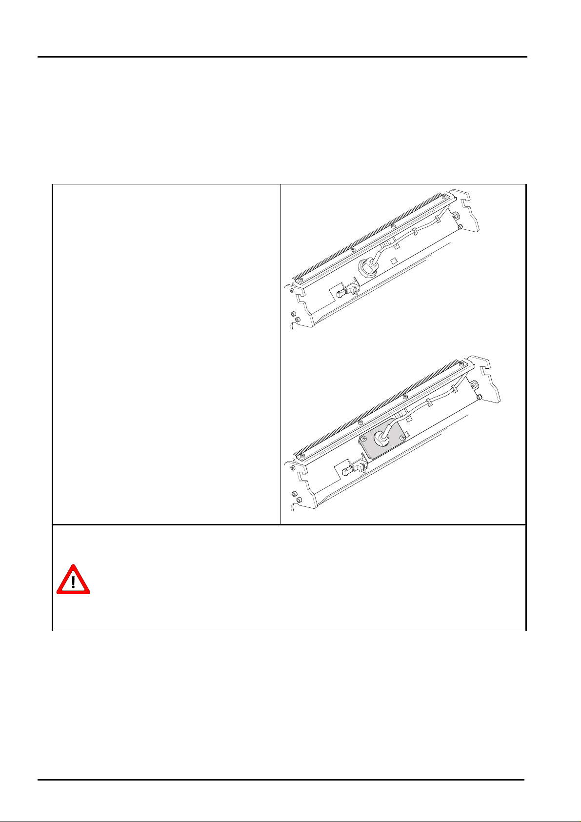
Symptom: Film runs askew through the decurl uni t
or
Display "remove output jam" in combination with the error message " 6C4E6
or 6C4BF" (see local keypad, menu 10, print eng ine - error details)
Reason: Loose screws or several screws missi ng on t he decurl rol ler flange, (see
figure 1)
- Due to the missing screws the flange may shift and t hen t he r oller s ar e no
longer parallel to the film transport level.
This happens mainly in machines manufactured prior to October 1998.
Cure:
Check, if the screws are ful l y tightened and i f t hey are complete
The screws are visible after removal of the decurl heat protection cover and the
corresponding decurl side panels.
- If the screws have not been fully tightened:
• Tighten the screws:
On the left-hand side of t he decur l unit the wiring of the heater must be
removed as well.
• Replace the decurl unit at the next occasion.
- If one or more screws are missing:
• Replace the decurl unit.
Figure 1a
left hand view
(The decurl side panels are removed in these views)
Symptom: Film runs askew through the decurl uni t
or
Revision 22 Type 5361 Section 6.3 / 5
Figure 1b
right hand view
Page 7
Repair and Service DD+DIS053.00E
Troubleshooting
Display "remove output jam" in combination with the error message " 6C4E6
or 6C4BF" (see local keypad, menu 10, print eng ine - error details)
Reason: Transport roller shaft of the film take over no longer parall el .
- If the shaft is not parallel, the film may enter the decurl unit at an angle or
even fail to reach the decurl unit.
This may be the result of e.g . to much force on the opened film take over
unit.
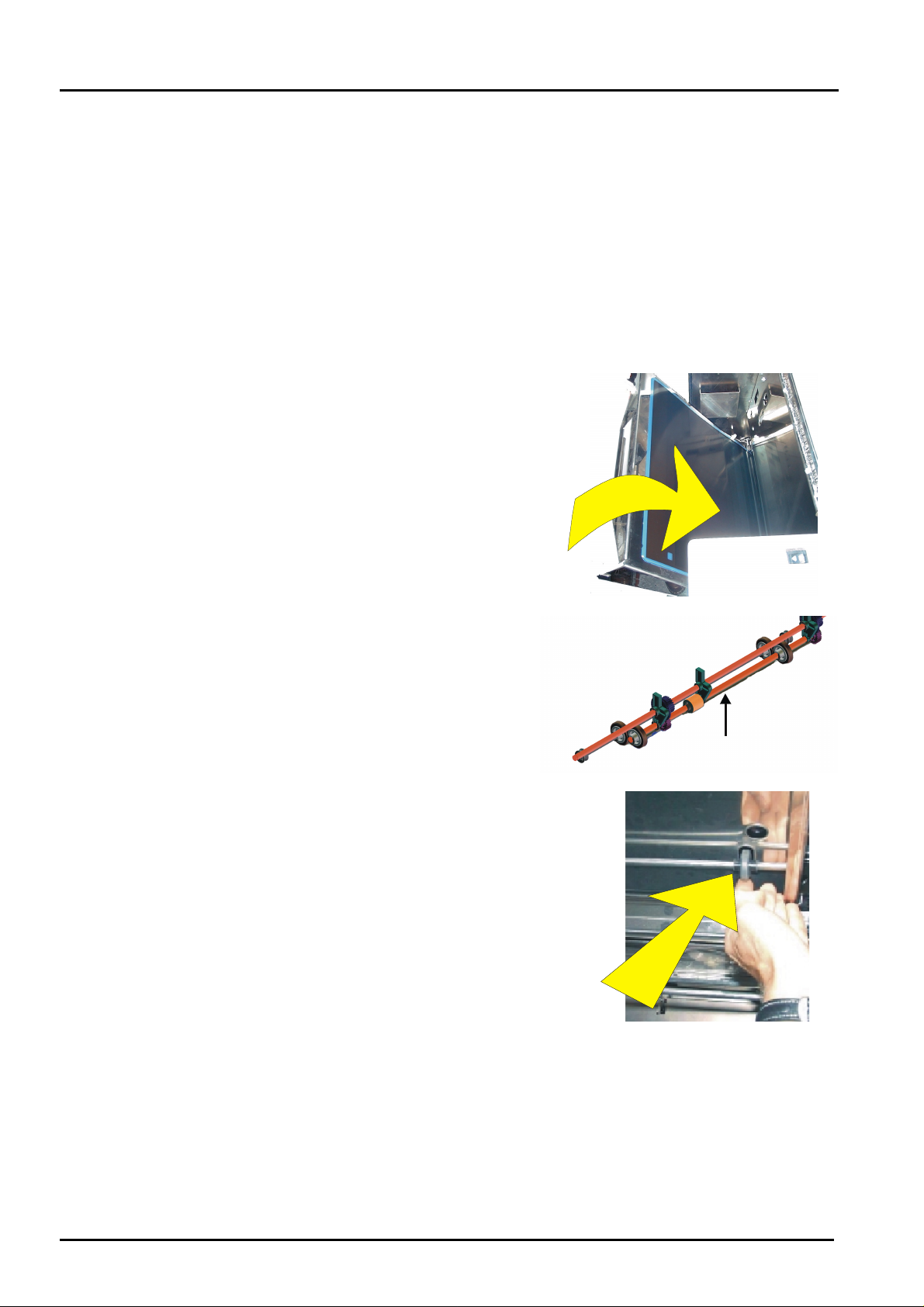
Cure: Check, if the film take over unit transport s t he f i lm straight (parallel).
- Roller pressure on the film must be uniform,
• insert a film in the film take over
unit.
• Close the film take-over unit.
• Lift the shaft slightly on the drive
side of the horizontal film
aalignment.
• Check the pressure on the film on
both rollers.
- In case of pressure differences:
• align the shaft in parallel,
or
• replace the film take over unit.
Symptom: Film runs askew through the decurl uni t
Section 6.3 /6 Drystar 3000 (Type 5361) Revision 22
Page 8

DD+DIS053.00E Repair and Service
Troubleshooting
or
Display "remove output jam" in combination with the error message " 6C4C0"
(see local keypad, menu 10, print engine - er ror details)
Reason:
Turning of one of the bearing blocks for the decurl rollers.
- This may happen on either side, right or left, when a film has been pulled
out of the decurl unit with undue forc e.
The last decurl roller is then no longer par allel – the film runs askew.
Cure: Correct positioning of the bearing block.
• Lift the shaft by means of a screwdriver, as shown in Fig. (see arrow "lift
axle"), and turn the bearing block back to its correct position, either
manually or again with a screwdriver.
bearing
Okay
Not Okay
Or
• If this is not a permanent solution for the problem:
replace the decurl unit by the reworked decurl unit which hs been introduced
in the production line, (see page 4).
Revision 22 Type 5361 Section 6.3 / 7
Page 9

Repair and Service DD+DIS053.00E
Troubleshooting
1.4 Symptom: Drystar 3000 does not print. No error message is displayed.
.
Reason:
Either the image does not get t o the printer (network) or printer configuration mismatch
Cure:
• Start IMOS Drystar3000
• Enter Menu „Application - Customization - Name/Value Edit“
• Look to the drivers with extension „11“: The list of these components should look like
displayed here
• In case it does not look like that , reconfigure the output of t he pr inter as Drystar 3000.
Select „force pin“ in the configuration screen.
• In case the drivers for the print engine are okay, have a closer look to the drivers for
networking: Note: In t he example enclosed only the driver for APIP is loaded. In case the
Drystar 3000 is connected to a host modality via DICOM, lp, pap or ftp, different drivers
may be loaded.
Section 6.3 /8 Drystar 3000 (Type 5361) Revision 22
Page 10

DD+DIS053.00E Repair and Service
Troubleshooting
Note: In the example below only the driver for APIP has been loaded. If the Dr ystar 3000
is connected to a host modality via DICOM, lp, pap or ftp, various dr ivers ma y be
loaded.
Network Protocol Drivers
APIP CMNXXX21
ETHXXX21
DICOM CMNXXX22 (or higher)
PMSXXX22 (or higher)
FTP CMNXXX?? (?? > 21)
LP CMNXXX?? (?? > 21)
PAP CMNXXX?? (?? > 21)
PAPXXX?? (?? > 21)
For further information see section „Troubleshooting Ethernet failures“
• In case the driver is not installed, use t he pr oper network configurator to reconfigure the
network connection. See section 5 for mor e information.
Revision 22 Type 5361 Section 6.3 / 9
Page 11
Repair and Service DD+DIS053.00E
Troubleshooting
1.5 Symptoms: Image fault
Cause: Either problem of image processing (software/hardware) or a problem of the host
system.
The listing below shows possible error symptoms:
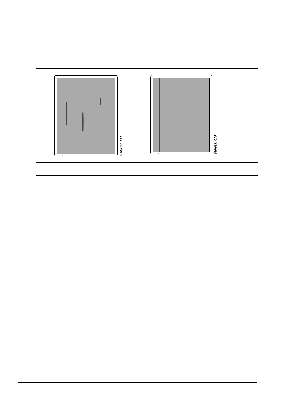
Symptom 1:
Vertical, blurred, dark lines
Reason: Dust. Dust is the main enemy of t he
Drystar 3000
Cure: Normally okay after next film, otherwise
clean TH (ref. to Sec.12) . Leave TH com par t -
ment closed. Leave film loading assembly
closed.
Symptom 2:
Vertical, sharp, dark line(s)
Reason: Resistor of TH g oing to be defective.
Cure: Exchange TH (ref . to Sec 6.5).
Section 6.3 /10 Drystar 3000 (Type 5361) Revision 22
Page 12

DD+DIS227.01E Repair and Service
Troubleshooting
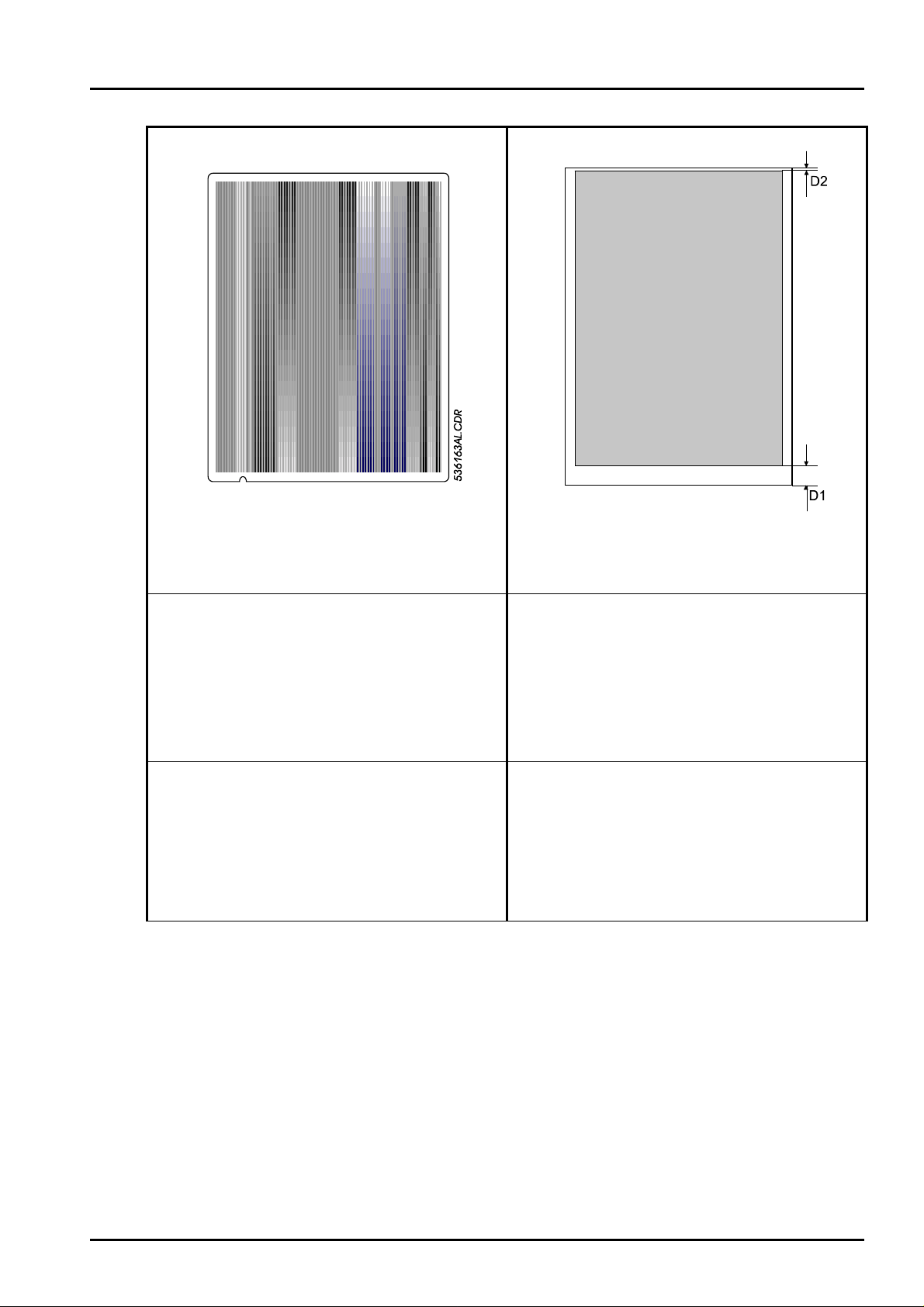
Symptom 3:
Vertical, sharp, white line, <1mm
Reason: Defective resistor of the thermal
print head.Might also be some dust.
Symptom 4:
Horizontal lines (at right angle to the film
transport direction, spacing 3-4 mm ) .
Reason: Irregularities in t he film transport
system (mechanical problem).
- Flat belt
- Toothed belt
- Thermal head drum
Cure: Clean TH (see Sec. 12). If image
quality does not improve, exchange TH (ref.
to Sec. 6.5).
- Drum motor
Cure:
- Check the drum motor, if necessary,
install the improved drum motor
(CM+3097781).
- Check the drum, belts (belt t ension) and
belt pulleys (bearings).
Revision 28 Drystar 3000 (Type 5361) Section 6.3 / 11
Page 13

Repair and Service DD+DIS053.00E
Troubleshooting
Symptom 5:
Thermal print head - banding:
(a) Stripes narrow (few mm) to wide (some
cm) become visible in a grey field in film
transport direction (flat3001.bla or
flat3002.bla)
(b) Slight scratches on the emulsion side
Reason:
(a) Dirt on t he thermal print head.
(b) Ther mal print head compensation drift
Cure:
(a) Clean the t her mal print head with a hard
eraser (for ink, e.g. Pelikan BE20, order
no. 1BE20 602169, also refer to the
FSB 025.98E).
(b) Perform a print head macro-compensa-
tion.
Symptom 6:
The image inform at ion is not in parallel with
the film edges
Reason:
- Vertical alignment incorrect: The st ops in
the film feed stat ion ar e not on the same
level.
Cure:
Adjust a vertical alignment (ref. to Sec. 6.6).
Section 6.3 /12 Drystar 3000 (Type 5361) Revision 22
Page 14
DD+DIS053.00E Repair and Service
Troubleshooting
Symptom 7:
Stripes appearing on the film
Irregular, light stripes of different densit ies
visible in film transport direction.
Reason:
Symptom 8:
The upper and the lower edge of the image
information do not have the same distance
to the film edge (D1 and D2). The vertical
adjustment of the image is not correct.
Reason:
- After replacing or dismounting t he TH, the
pressure of the film against the thermal
print head may be uneven.
- Due to age related slackening of t he
spring force, the pressure of the film
against the thermal print head is uneven.
Cure:
Adjust the pressure of the film against the
thermal head again and use the adjustment
kit with the order no. EB+53611750
TOOLKIT TO ADJUST TH PRESSURE for
this purpose.
The toolkit comes with application
instructions.
- Vertical alignment out of adjustment: The
stops in the film feed st at ion are too high
or too low.
Cure:
Adjust the vertical alignment
(ref. to Sec. 6.6).
Example: If the upper border is smaller than
the lower border, the stops are too far up.
Revision 28 Drystar 3000 (Type 5361) Section 6.3 / 13
Page 15

Repair and Service DD+DIS053.00E
Troubleshooting
Symptom 9: Symptom 10:
Stripes appearing on the film
Regular stripes in horizontal direction at a
distance of approx. 15 mm across the whole
film.
Reason:
- Encoder of the drum speed detection
defective.
- Contact problems with the cable to the
encoder of the drum speed detection.
Cure:
• Replace the encoder of the drum speed
detection (ref. to Sec. 6. 5) .
Stripes or scratches appearing on the film
The film is scratched on the emulsion side.
The scratches look like a ribbon running
across the whole film from top to bottom.
When the scratches get worse, the density in
the scratched areas decreases. It then looks
like the well-known "TH banding“.
This type of dirt on the TH cannot be det ected
with the bare eyes.
Reason:
- Dirt on the thermal print head.
Cure:
• Clean the thermal print head with a hard
eraser (for ink, e.g. Pelikan BE20, order
no. 1BE20 602169, also refer to the
FSB 025.98E).
Section 6.3 /14 Drystar 3000 (Type 5361) Revision 22
Page 16

DD+DIS053.00E Repair and Service
Troubleshooting
Symptom 11:
Wide, dark, regular vertical stripes. The stripes
correspond to the shape of the decurl r oller s .
This probably also affects the t her m al head
area, (see verification on the following pag e) .
Note: The example, shown here, is the print of
a "flatfield" t est . In the clinical image the stripes
are superimposed to the image information.
The stripes must not necessarily be symmetric.
Probably they are only visible on one side.
Reason:
1. Most likely dirt on the infrared sensor
Through the dirt the tem perature sensor
measures a lower temperature which then
results in a higher decurl temperat ur e.
Contamination due to light part icles which
are shed by the film.
If this is the case, white dust may be found
in the area of the decurl unit and the
thermal head.
2. Other possible causes:
- IR sensor defective
or
- PMC1 Board defective
Revision 28 Drystar 3000 (Type 5361) Section 6.3 / 15
Page 17
Repair and Service DD+DIS053.00E
Troubleshooting
To verify the symptom proceed as follows:
• Start IMOS
• Print testfilm „flat3001.bla“ and „flat3002.bla“ (IMOS: Repair – Pr int Engine – Print Testpage)
• Print Testfilm „artifac2.bla“
• Put the film „artifac2.bla“ on this flatfield film, where the im age fault is best visible.
• Put them on the lightbox.
• In case the problem is really originated by the decurl-rollers, you will see the f ault-pattern on the
displayed decurl rollers on the„artifac2.bla“ film.
Cure:
1) Clean the IR sensor /
replace the decurl unit
- in all machines manufactured up to mid-
October 98, (see Fig. ) , the decurl unit
must be replaced since the IR sensor is
hardly accessible.
- In machines with a separately mounted IR
sensor (see Fig.) remove the IR sensor
and clean it. Do not open the adjusting
nut. These must only be loosened for
replacement of the temperature sensor.
Please make sure to consider the hints
on the decurl unit
2) Replace the IR sensor
3) Replace the PMC1 Board
For removal instructions, see section 6.5
of the Drystar 3000 documentation.
When removing the decurl unit, please consider the following points:
531130a.CDR
- If there are any light particles / dust in t he m achine, remove them with a vacuum
cleaner.
- Never use compressed air to remove them since this would distribute the particles
all over the machine and its surroundings.
Section 6.3 /16 Drystar 3000 (Type 5361) Revision 22
Page 18
DD+DIS053.00E Repair and Service
Troubleshooting
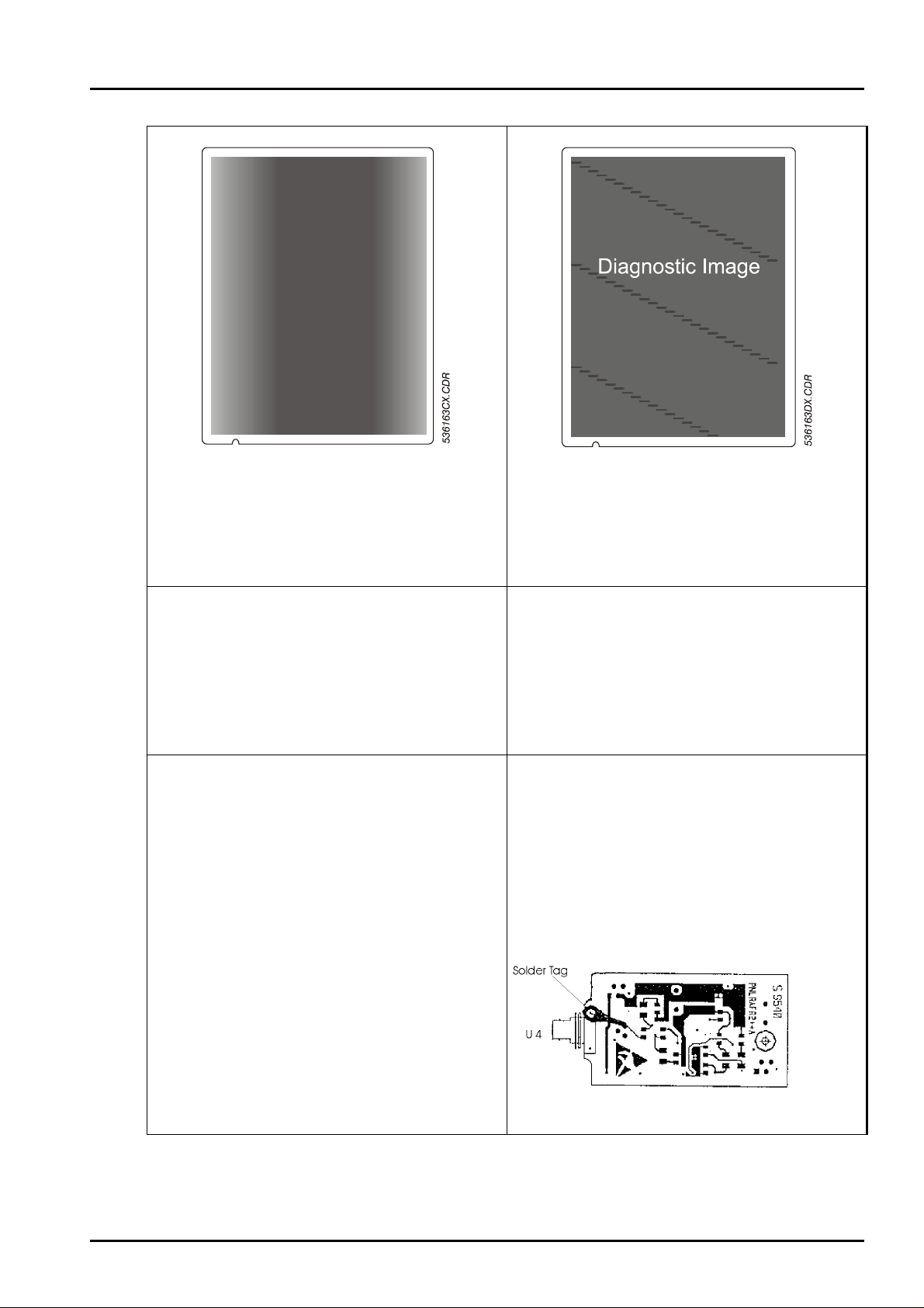
Symptom 12: Symptom 13:
Uneven density at the right and left hand side
of the image. Density is too low compared t o
the middle part of the imag e. Best visible on a
flatfield.
Reason:
- Heat conducting material of thermal head
not homogeneous anymore (should only
happen for devices with SN<1895).
- TH pressure adjustment not correct
anymore (see section 6.6, adjustments).
Cure:
• Check TH pressure (see section 6.6,
adjustments).
• Replace thermal head. New thermal
heads use a new, pink heat conducting
material.
Moiré pattern: Dots or lines, appearing in
regular distance over the whole film. Spor adic
(intermittent contact) or m ost often persistant.
Appearance depends on frequency of the
video signal (i.e. may differ from one to
another installation).
Reason:
- Interrupted ground connection between
the AFR2 Board rev. A and the housing
Cure:
• Possibility 1: Provide the missing ground
connection between PCB and housing by
soldering a solder tag. These solder tags
are available in packages of 100 including
the instructions (EB+44022720).
• Possibility 2: Installation of the AFR2
Board, Rev C, available as spare part.
(EB+44022622).
Revision 28 Drystar 3000 (Type 5361) Section 6.3 / 17
Page 19

Repair and Service DD+DIS053.00E
5
36163AYCD
R
Troubleshooting
Symptom 14
One (or more) thin horizontal dar k line in the
image. Initially sporadic, later on it might even
be in every image. Eventually a bright line is
visible above the dark one.
Symptom 15:
536113AO.CDR
Vertical bright lines
Thin vertical bright lines across the comp let e
film.
Reason:
- Most likely rust on the shaft assembly
bushing. As this bushing is one of 3
supports of the TH in print position, it is
possible, that a non-defined support
position can lead to small slipping down of
the TH during printing.
Cure:
Dismount the shaft assembly and grease t he
bushing (for instrcutions see section 13,
DD+DIS013.99M). Note 1: In all devices with
SN > 1916 (+ additional SN1911) the bushing
is greased already. Note 2: This gr easing has
to be done only once in a lifetime.
Reason:
- 1) Software problem on the
COS Board revision E.
Note: The problem should not occur in
machines with SN < 2177 (+ SN 2171;
2172; 2173 in addition).
In these machines the COS Board rev. F
is already installed.
- 2) Hardware problem on the AIC1 Board
Cure:
• 1) Installation of the
Software Version ≥ 1.73.
During the software installation ther e
is an automatic update of the
firmware of the COS Board to rev. F.
• Installation of the COS Board r e v. F
(EB+53610593)
• 2) Replacement of the AIC1 by a
AIC1 Board, Rev. F (EB+53611092).
The THP1 Board previously mounted
on the modified data cables is now
integrated on AIC1 Board, rev. F and
is thus no longer necessary.
Section 6.3 /18 Drystar 3000 (Type 5361) Revision 22
Page 20
DD+DIS053.00E Repair and Service
Troubleshooting
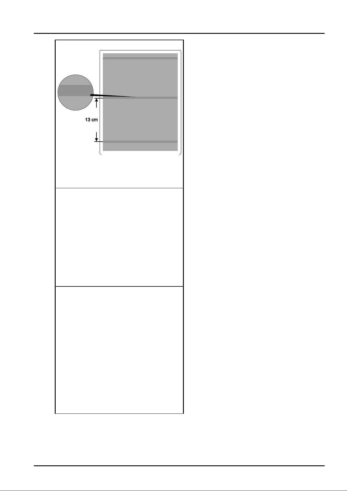
Symptom 16:
Horizontal bright lines
Horizontal lines (banding).
Reason:
- If the printer is out of oper at ion for a
longer time period, the flat belt of the
main drive may suffer permanent
pressure marks due to the belt t ension.
These pressure marks on the flat belt
result in irregularities of the film
transport system, and thus also in
image artifacts (horizontal lines at a
spacing of
approx. 13 cm)
Cure:
Measures for the production:
• At the production line, the flat belt is
detached again after the pr int er has
been calibrated and the belt tension
has been mounted at the belt pulley.
• The flat belt must be mount ed again for
the first operation of the machine.
Measures for already installed machines:
• Replacing the flat belt
For removal and mounting of t he flat belt
refer to your documentation section 6. 5
Adjustment of the belt tension and belt
positioning of the main drive see
documentation section 6.6.
Revision 28 Drystar 3000 (Type 5361) Section 6.3 / 19
Page 21
Repair and Service DD+DIS053.00E
Troubleshooting
1.6 Symptom: Hard disk doesn’t work Hard disk doesn’t work
Reason:
end of boot message: (boot m essage see 3.5)
==> Wait until disk HD0 is ready
1 (Can not select [11])
** Error, Drive C: not ready
mon>
Blinking keypad cursor
Red CPU LED lights up
- Wrong SCSI address coding (only for new installed hard disk!).
- Bad contacts of cable connector.
- Eventually missing power supply for hard disk or defective hard disk.
Cure:
• Type "dos" on monitor level (Drystar_C:\mon <enter>; Mon>DOS <enter>) to be able to
execute dos commands on monitor level. The command "dir " should in any case give you
the contents of the hard disk if the connection can be achieved.
Type "he" to get more information on the "mondos" tool. Type "q uit " to leave the mondos
level.
• If command "dir" doesn`t work check cable connection to the hard disk and power supply.
• Replace hard disk or CPU if necessary
1.7 Troubleshooting Ethernet failures
Symptom: No print i ng via Ethernet
In spite of config ur at ion for network connection no printing via Ethernet is possible.
Reason:
HARDWARE
- Cabling (not RG-58; short circuit; not connected, not terminated by 50 Ohm terminator )
- BER board
- MAU (see green LED = power. Off means BEN or MAU. problem)
- Drop cable, internal Drystar 3000 Ethernet cable.
SOFTWARE
- Ethernet not configured
- Problem in ART table (mismatch of sm all/ capital letters; typing error)
- mismatch of apip_dest_names.
- Not enough diskspace for the network user 4 (or 5 to 9) in the printer where you want to
print the image.
Section 6.3 /20 Drystar 3000 (Type 5361) Revision 22
Page 22

DD+DIS053.00E Repair and Service
Troubleshooting
Tools for troubleshooting:
TROUBLESHOOTING HARDWARE
Make a reset of the print er . Start "rem" (logbook) on te r m inal level. Type "go" and have a
look to the first page of information. You should ge t som ething like:
TNX ethernet address 00-66-00-27- 6f-00 (=BEN ethernet adddress)
TNX selftest MAC okay (=one function of BEN SONIC chip)
TNX selftest ENDEC ok ay (= encoder /decoder function of SONIC
chip)
TNX selftest cable okay (=check of fuse and cable)
TROUBLESHOOTING SOFTWARE
• look to the whole customization list: type NVE at the AO S shell pr om pt. You have to get
ETHXXX21 driver at the end. O therwise it seems that Ethernet is disabled.
• type "adv" to get the whole list of all Ethernet nodes in your network ("adv" means
"advertise").
Comment: "adv" is much better than using "ping", because you do not have to know the other
nodes addresses or names. It’ s advised to use „ping“ (e. g. ping 192..9.200.101)
for connections to non-AGFA printer s ( Workstations !)
1.8 What to do if a bus error occurs ?
• Start IMOS Drystar 3000. No connection will be established. Select "Terminal"
Possible message: "RC" or "mon"*
• Perform a reset on the VME CPU or type "res"
• Stop the system boot up before the application SW will be started: Press ENTER
key as soon as the "AOS started" message appears.
• Remove all VME interfaces except the CPU
• Perform a reset: Now the system should boot up without bus crash. If a bus crash
occurs now, remove the NIP and BER board, too.
• Insert one interface after another. Make a reset in between. Like that the faulty
interface can be detected.
*In case a bus crash register dump is displayed, the following list will help to troubleshoot:
By looking on the "fault address" you can verify in the listing below the "fault" address
Address - Range Device Address - Range Device
00000000 - 07FFFFFF Memory module F7FE8400 - F7FE87FF CPU board
10000000 - 17FFFFFF Memory module F7FE8800 - F7FE880F BER
17800000 - 17FFFFFF LUT NIP F7FE8880 - F7FE888F BER
D0000000 - D7FFFFFF NIP F7FE8900 - F7FE89FF CPU board
E0000000 - E00FFFFF VSI F7FE8A00 - F7FE8AFF BER
EA000000 - EA1FFFFF COS board F7FE8B00 - F7FE8B1F NIP
EA200000 - EB000000 AI C boar d F7FE8C00 - F7FE8EFF CPU board
EF004000 - EF004800 AIC board F7FE8F00 - F7 FE8F0F BER
F2000000 - F2FFFFFF BER board F7FE8F20 - F7FE8F2F BER
F7FD0000 - F7FDFFFF CPU board F7000000 - FFEFFFFF CPU boar d
F7FE8001 - F7FE82FF CPU baord
F7FE8300 - F7FE83FF BER
Remark: When an addressing failure occur s , t his might have other causes than a
malfunctioning board on the corr esonding address. E g. a - malfunctioning - boar d
that responds to an addressing cycle of another board.
Revision 28 Drystar 3000 (Type 5361) Section 6.3 / 21
Page 23

Repair and Service DD+DIS053.00E
Troubleshooting
1.8.1 Bus crash caused by COS board
COS boards < rev. E in a few rare circumstances (e. g. at very low temperature) can cause a
sporadic buscrash. The printer will automatically reset as long as the buscrash exists. A logfile
(IMOS Drystar 3000 → TOOLS → terminal; "log to file") will show
BUS ERROR at addr ea000000 (or from EA000000 to EA1FFFFF r espectively).
It is recommended to install SW release 1.6 or higher in this case. Software rel. 1.6 contains a
software upgrade for t he COS board. In case the problem is not solved with this measure,
replace the COS1 board to a board with rev. E or higher.
1.8.2 Spurious Interrupt
The reason is mostly a hardware problem, so check the j um pers on all boards and if
necessary replace the VME board.
1.8.3 Illegal instruction
Mostly a software problem. Make a new installation of the complete software, check the VME
boards or replace them.
2 Software Installation / Configuration from Scratch
In case of troubles during inst allat ion or r epair , it is sometimes advised to reconfigure the
device or even to install the software from scrat ch.
Enclosed a brief instruction:
2.1 Software Installat ion from Scratch
Tools needed: Laptop; IMOS Drystar 3000; Device SW (e.g. rel 1.32)
Proceeding:
• Start IMOS Drystar 3000
• Make a backup
• Select INSTALL SW: Reinstall System (see HELP IMOS Drystar 3000 for m or e information)
• Insert the floppies as requested
• Make a restore of the TH data only
• Make a new configuration (see next topic)
2.2 Configuration from Scratch
Tools needed: Laptop, IMOS Megacon; eventually IMOS DICOM and / or MPS
Proceeding:
• Be sure, that all .a00, .c00 and .u00 on t he C: and D: partition are removed.
• Start IMOS Megacon
• Select for input / output / network the required modules. Choose "f or ce pin" at the different
inputs/outputs.
• Eventually afterwards make a selective restore of the LCD and MNU .U00 parameters.
Alternatively make a new customisation of the pr inter, if required.
Section 6.3 /22 Drystar 3000 (Type 5361) Revision 22
 Loading...