

Page 1

Annotation
Software
for Microsoft® Windows
User manual
®
Page 2

A
NNOTATION SOFTWARE
© Agfa-Gevaert N.V. 2000.
No parts of this document may be reproduced, copied, adapted or transmitted in any form or by any means
without the written permission of Agfa-Gevaert N.V.
Agfa-Gevaert N.V. makes no warranti es or repre sentation, expressed or implie d, with respe ct to the ac cu-
racy, completeness or usefulness of the in formation c ontained in this d ocument and sp ecifically disc laims
warranties of suitability for any particular purpose. Agfa-Gevaert N.V . sh all under no circumstances be liable
for any damage arising from the use or inability to use any information, apparatus, method or process disclosed in this document.
Agfa-Gevaert N.V. reserves the right to make changes to this document without prior notice.
Agfa-Gevaert N.V., Septestraat 27, B-2640 Mortsel, Belgium.
Annotation Software is a trademark of Agfa-Gevaert N.V., Belgium.
Agfa and Agfa-Rhombus are trademarks of Agfa-Gevaert AG, Germany.
2
2272A GB 20001222
Page 3

A
NNOTATION SOFTWARE
Table of contents
Chapter 1: Introducing the Annotation Software................. ........... .......... ....... 5
About the Annotation Software.................................. ......................................6
Annotation Software features.......................................................................... 7
Chapter 2: Using the Annotation Software......................................................9
Adding an annotation...................................... ........... ....................................10
Showing/hiding annotations....................................................................... 10
Showing/hiding grid lines...................................................................... ..... 11
Measuring a distance................................................................................. 13
Calibrating distance measurements........................................................... 15
Measuring an angle......................................................... ........... .......... ..... 19
Calculating th e scan average level within a region of interest (ROI)............21
Calculating a dens ity profile....................................................................... 23
Drawing a line............................................. ..................... ..................... ..... 25
Drawing an arrow .................................................. .......... ........... .......... ..... 27
Drawing a geom e tric form................. ..................... ..................... ............... 29
Adding text................................................................................................32
Setting predefined texts.................... .......... ........... .......... ........... .......... ..... 34
Editing an annotation...................................................................... ...............36
Deleting an annotation.......................... ......................................................... 38
Saving an annotated image................................................. ........... ...............40
2272A GB 200012 22
3
Page 4

A
NNOTATION SOFTWARE
4
2272A GB 20001222
Page 5

Introducing the Annotation
This chapter covers the following topics:
Chapter
Software
1
q About the Annotation Software
q Annotation Software features
Page 6

ANNOTATION SOFTWARE
About the Annotation Software
The Annotation Software is an add-on program extending the basic
annotation functions of the QC Viewer Software.
The Annotation Software User manual provides general and practical
information on using the Annotation Software. For full details on using the
Annotation Software in combination with the QC V iewer Software, refer to the
QC Viewer Software Reference manual or the QC Viewer online Help.
6
Introducing the Annotation Software
2272A GB 20001222
Page 7
ANNOTATION SOFTWARE
Annotation Software features
The Annotation Software permits you to add annotations to images and to
perform measurements. You can:
• Measure distances.
• Calibrate distances.
• Measure angles.
• Calculate the scan average level within a region of interest (ROI).
• Calculate density profiles.
• Draw lines.
• Draw arrows.
• Draw geometric forms (rectangles, ellipses, polygons).
• Add custom texts and predefined texts.
As an aid when performing measurements or calculations or when adding
annotations, you can display grid lines on the image.
Annotations can be shown or hidden.
v
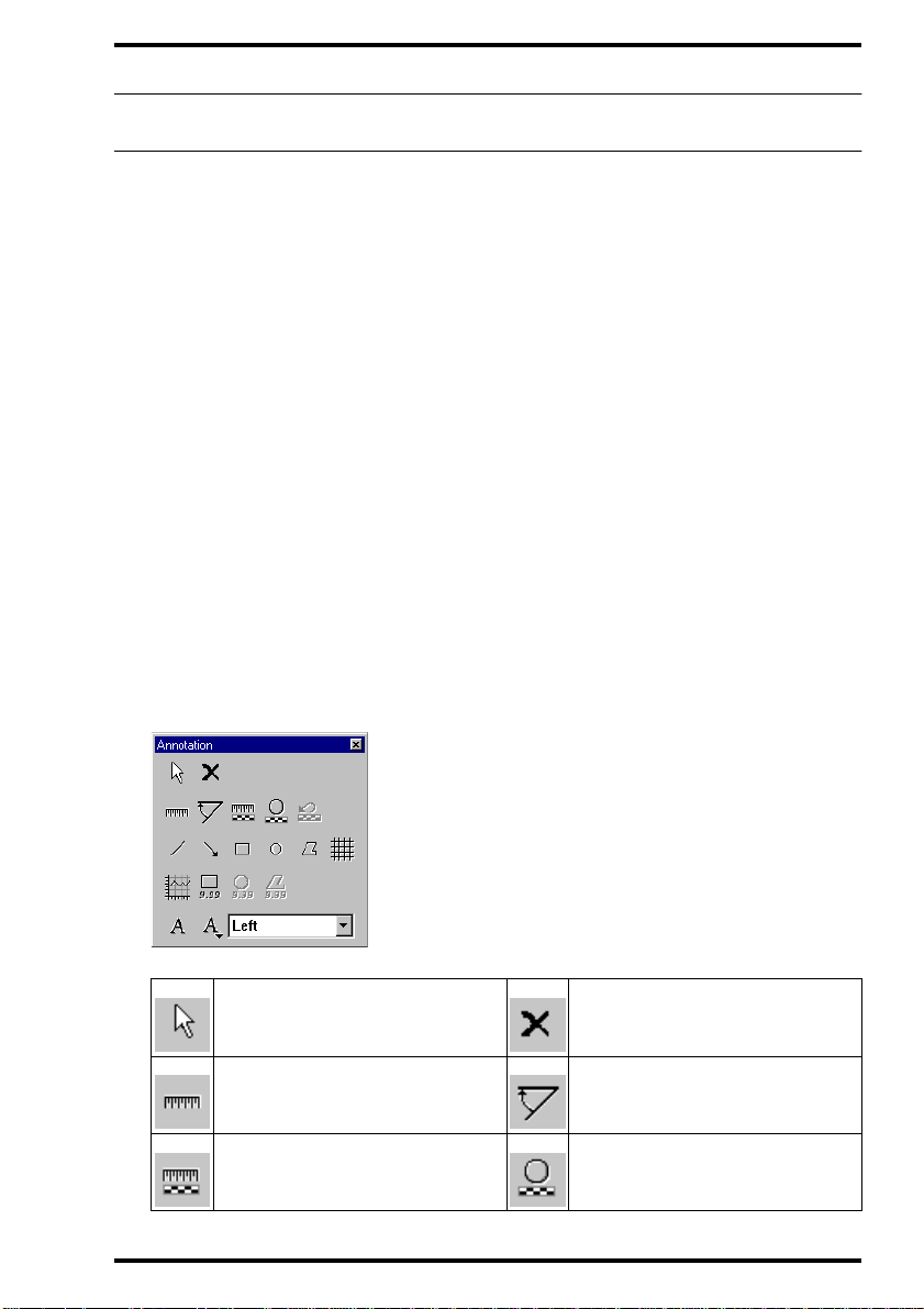
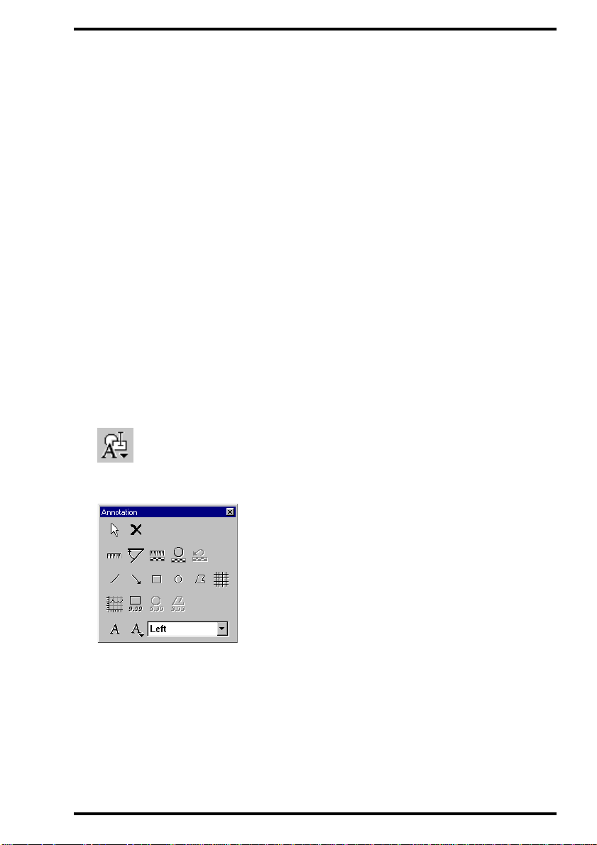
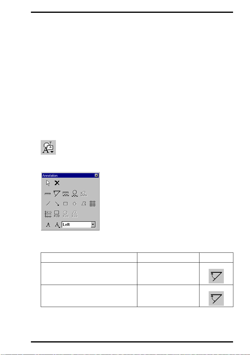
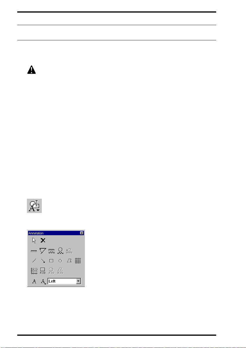
You can access the above annotation functions via the buttons on the
Annotation toolbar
2272A GB 200012 22
Annotation toolbar
Select button Delete button
Distance button Angle button
Line Calibration button Circular Calibration button
Introducing the Annotation Software
7
Page 8

ANNOTATION SOFTWARE
Revert Calibration button
Line button Arrow button
Rectangle button Circle button
Polygon button Grid button
Density Profile button Rectangular ROI button
Circular ROI button Polygonal ROI button
Text button Predefined Text button
8
Introducing the Annotation Software
Predefined Text box
2272A GB 20001222
Page 9

Chapter
Using the Annotation Software
This chapter covers the following topics:
q Adding an annotation
q Editing an annotation
q Deleting an annotation
q Saving an annotated image
2
Page 10

ANNOTATION SOFTWARE
Adding an annotation
The ADC Annotation Software permits adding the following annotations to
images: lines, arrows, geometric forms (rectangles, circles, and polygons),
predefined text, and custom text. Additionally, distance and angle
measurements can be performed. Distance and angle measurements can be
calibrated if the image includes a calibrated object. Images can be viewed
with annotations turned on or off.
Furthermore, the scan average level and the histogram can be determined for
regions of interest and density profiles along lines can be displayed.
Showing/hiding annotations
If annotations have been added to an image, you can choose to show or hide
the annotations.
v
Turn on annotations before adding annotations or performing
measurements or calculations.
v
If you turn off annotations and save the result, the annotations are not
lost. At any time, you can turn annotations on again.
To turn annotations on or off:
On the View menu, click Annotations.
A check mark means that annotations are turned on. If the image has annotations,
the image with its annotations is displayed in the image pan e .
10
Using the Annotation Software
2272A GB 20001222
Page 11
ANNOTATION SOFTWARE
Showing/hiding grid lines
When you wish to add annotations to an image or perform measurements, it
can be useful to display grid lines on the image.
To turn grid lines on:
1 Make sure annotations are turned on.
Refer to
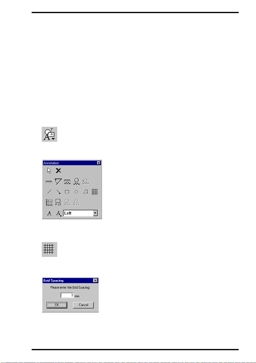
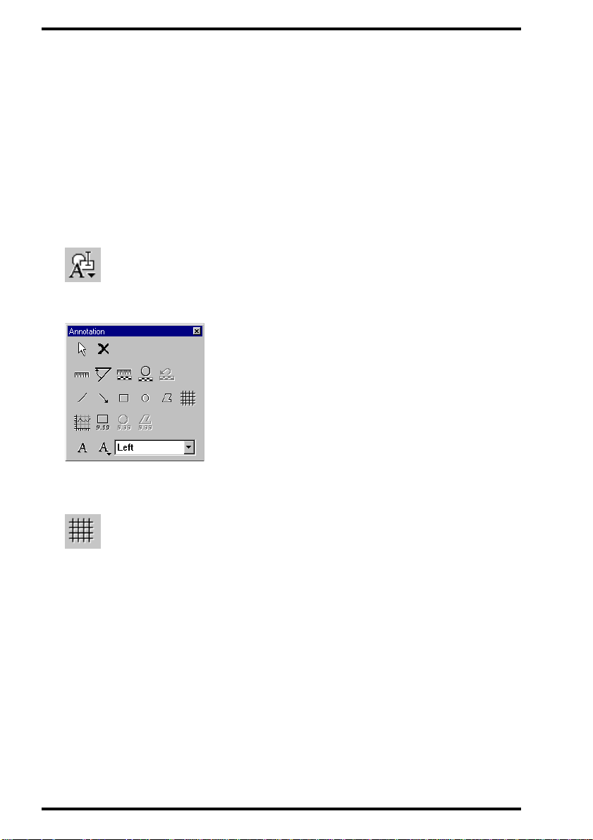
2 On the Tools menu, click Annotation.
Alternatively, you can click the Annotation button on the Standard toolbar.
The Annotation toolbar is displayed.
’Showing/hiding an notations’
on page10.
3 Click the Grid button.
The Grid Spacing dial og box is displayed.
2272A GB 200012 22
Using the Annotation Software
11
Page 12
ANNOTATION SOFTWARE
4 Type the grid spacing.
The regional settings of your ADC QS Station determine the unit of length.
5 Click OK.
Grid lines are displayed.
To turn grid lines off:
1 On the Tools menu, click Annotation.
Alternatively, you can click the Annotation button on the Standard toolbar.
The Annotation toolbar is displayed.
2 Click the Grid button.
Grid lines are hidden.
12
Using the Annotation Software
2272A GB 20001222
Page 13
ANNOTATION SOFTWARE
Measuring a distance
Via the Annotation toolbar, you can measure the distance between specific
features in an image. If you have not calibrated the distance measurement
using a reference object in the image, the measurement is referenced against
the image plate dimensions.
v
If you wish to use calibrated distance meas urements, calibrate first. Refer
to ’Calibrating distance measurements’ on page 15.
To measure one or more distances:
1 Make the image on which you wish to measure the active image.
You can click the image either in the thumbnail pane or in the image pane.
2 Turn on annotations.
Refer to
3 On the Tools menu, click Annotation.
Alternatively, you can click the Annotation button on the Standard toolbar.
’Showing/hiding an notations’
on page10.
The Annotation toolbar is displayed.
2272A GB 200012 22
Using the Annotation Software
13
Page 14

ANNOTATION SOFTWARE
4 Measure the distances:
To Do this Button
Measure one distance
Measure several distances
The pointer is now a standard pointer and a ruler.
Click the Distance
button.
Double-click the
Distance button.
5 Click once to define the starting point of the measurement, move the pointer,
and click again to define the end.
As you move the pointer, the dist ance between the starting point and the pointer is
displayed. The regi onal settings of your ADC QS Station determine the unit of
length.
After you have clicke d to define the end of the measurement, the measured
distance is displayed. You can move the distance label by dragging it. You can
resize the distance label by dra gging a sizing handle of the label.
6 To measure several distances, repeat step 5.
7 To save the measurement, either replace the existing image or save the
changed image as a new image.
Refer to
É To modify the measured distances, refer to
’Saving an annotated image’
36
page
.
on page40.
’Editing an annotation’
on
14
Using the Annotation Software
2272A GB 20001222
Page 15

ANNOTATION SOFTWARE
Calibrating distance measurements
You can calibrate distance measurements using either a linear or a circular
reference object in the image. At any time, you can revert to the original
calibration.
Calibration applies only to the image for which you perform the
calibration.
To calibrate distances via line calibration:
1 Make the image with the linear reference object the active image.
You can click the image either in the thumbnail pane or in the image pane.
2 Turn on annotations.
Refer to
3 On the Tools menu, click Annotation.
Alternatively, you can click the Annotation button on the Standard toolbar.
’Showing/hiding an notations’
on page10.
The Annotation toolbar is displayed.
2272A GB 200012 22
Using the Annotation Software
15
Page 16

ANNOTATION SOFTWARE
4 Click the Line Calibration button.
The Calibration Distance dialog box is displayed.
5 Type the value for the distance which you will use as calibration distance.
The regional settings of your ADC QS Station determine the unit of length.
6 Click OK.
The pointer is now a standard pointer and a rul e r with a calibration bar.
7 Click once to define the starting point of the calibration distance, move the
pointer, and click again to define the end.
The calibration distance is displaye d. You can move the distance label by dragging
it. You can resize the distance label by dr agging a sizing handle of the label.
All distances whi ch you will measure will be referenced against the calibration
distance.
v
Previously measured distances are not recalculated.
8 To save the calibration, either replace the exis ting image or save the changed
image as a new image.
Refer to
É To modify the calibration distance, refer to
16
Using the Annotation Software
’Saving an annotated image’
page
36
.
on page40.
’Editing an annotation’
2272A GB 20001222
on
Page 17

ANNOTATION SOFTWARE
To calibrate distances via circular calibration:
1 Make the image with the circular reference object the active image.
You can click the image either in the thumbnail pane or in the image pane.
2 Turn on annotations.
Refer to
’Showing/hiding an notations’
on page10.
3 On the Tools menu, click Annotation.
Alternatively, you can click the Annotation button on the Standard toolbar.
The Annotation toolbar is displayed.
4 Click the Circular Calibration button.
The Calibration Distance dialog box is displayed.
5 Type the value for the diameter of the circle which you will use as calibration
distance.
The regional settings of your ADC QS Station determine the unit of length.
2272A GB 200012 22
Using the Annotation Software
17
Page 18

ANNOTATION SOFTWARE
6 Click OK.
The pointer is now a standard pointer and a circle with a calibration bar.
7 Click three points on the circumference of the calibration object.
The calibration distance is displaye d. You can move the distance label by dragging
it. You can resize the distance label by dr agging a sizing handle of the label.
All distances whi ch you measure on the present image will be referenced aga inst
the calibration distance.
Previously measured distances are not recalculated.
v
8 To save the calibration, either replace the exis ting image or save the changed
image as a new image.
Refer to
’Saving an annotated image’
on page40.
É To modify the calibration distance, refer to
36
page
.
’Editing an annotation’
on
18
Using the Annotation Software
2272A GB 20001222
Page 19
ANNOTATION SOFTWARE
Measuring an angle
Via the Annotation toolbar, you can measure the angle betwe en two features.
To measure one or more angles:
1 Make the image on which you wish to measure the active image.
You can click the image either in the thumbnail pane or in the image pane.
2 Turn on annotations.
Refer to
3 On the Tools menu, click Annotation.
Alternatively, you can click the Annotation button on the Standard toolbar.
The Annotation toolbar is displayed.
’Showing/hiding an notations’
on page10.
4 Measure the angles:
To Do this Button
Measure one angle Click the Angle button.
Measure several angles
The pointer is now a standard pointer and an angle.
2272A GB 200012 22
Double-click the Angle
button.
Using the Annotation Software
19
Page 20

ANNOTATION SOFTWARE
5 Click once to define the starting point of the first line, move the pointer, and
click again to define the end.
6 Click once to define the starting point of the second line, move the pointer,
and click again to define the end.
As you move the pointer, the angle between the two lines is displayed.
After you have clicked to define the end of the second line, the measured angle
(<180°) is displayed. You can move the angle label by dragging it. You can resize
the angle label by dragging a sizing handle of the label.
7 To measure several angles, repeat steps 5 to 6.
8 To save the measurement, either replace the existing image or save the
changed image as a new image.
Refer to
’Saving an annotated image’
on page40.
É To modify the measured angles, refer to
36
page
.
’Editing an annotation’
on
20
Using the Annotation Software
2272A GB 20001222
Page 21

ANNOTATION SOFTWARE
Calculating the scan average level within a region of interest (ROI)
Via the Annotation toolbar, you can calculate the scan average level (SAL)
within a rectangular region of interest (ROI).
To calculate the scan average level in one or more regions of interest:
1 Make the image on which you wish to calculate the SAL the active image.
You can click the image either in the thumbnail pane or in the image pane.
2 Turn on annotations.
Refer to
3 On the Tools menu, click Annotation.
Alternatively, you can click the Annotation button on the Standard toolbar.
’Showing/hiding an notations’
on page10.
The Annotation toolbar is displayed.
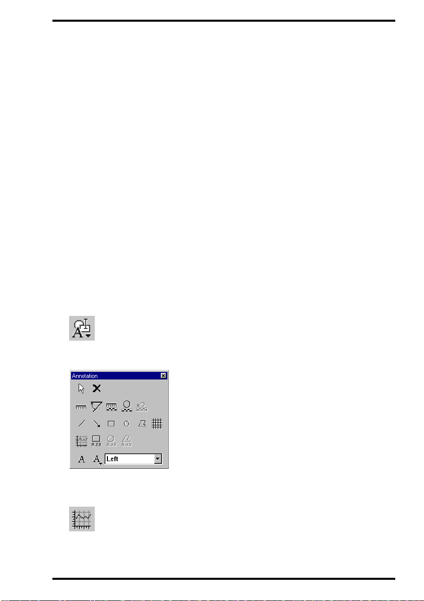
4 Select a form for the region of interest:
To mark Click Button
A rectangular ROI
2272A GB 200012 22
Rectangular ROI
button.
Using the Annotation Software
21
Page 22

ANNOTATION SOFTWARE
5 Mark the region of interest:
To draw Do thi s
1 Click once to define one corner.
A rectangular ROI
2 Move the pointer.
3 Click again to define the opposite
corner.
The scan average level (SAL) of the region of interest is displayed. Y ou can move
the SAL label by dragging it. You can resize the SAL label by dragging a sizing
handle of the label.
6 To calculate the scan average level (SAL) within several regions of interest,
repeat steps 4 to 5.
7 To save the regions of interest and the corresponding SAL values, either
replace the existing image or save the changed image as a new image.
Refer to
’Saving an annotated image’
on page40.
É To modify the region of interest, refer to
page
22
Using the Annotation Software
36
’Editing an annotation’
on
.
2272A GB 20001222
Page 23
ANNOTATION SOFTWARE
Calculating a density profile
Via the Annotation toolbar, you can calculate the density, i.e. the square root
of the exposure, along a line integrated over a rectangular area. If you have
not calibrated the distance measurement using a reference object in the
image, the length dimensions are referenced against the image plate
dimensions.
v
If you wish to use calibrated distance meas urements, calibrate first. Refer
to ’Calibrating distance measurements’ on page 15.
To calculate a density profile:
1 Make the image on which you wish to calculate the active image.
You can click the image either in the thumbnail pane or in the image pane.
2 Turn on annotations.
Refer to
3 On the Tools menu, click Annotation.
Alternatively, you can click the Annotation button on the Standard toolbar.
’Showing/hiding an notations’
on page10.
The Annotation toolbar is displayed.
4 Click the Density Profile button.
The blank Density Profile window is displayed.
2272A GB 200012 22
Using the Annotation Software
23
Page 24
ANNOTATION SOFTWARE
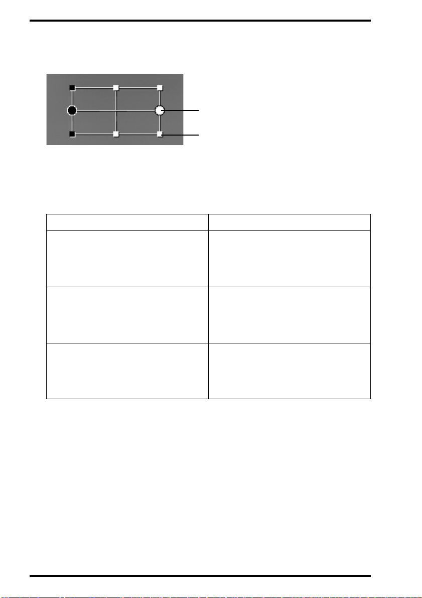
5 Click in the active image.
The density profile marker is displayed.
Rotating handle
Sizing handle
6 Position the density profile marker so that it covers the area for which you
wish to calculate the density profile.
The density profile will be calculated al ong the line between the circu lar rotating
handles, integrated over the area inside the density profile marker.
To Do thi s
1 Move the pointer to the center of
Shift the density profile marker
Resize the density profile marke r
the marker.
The pointer is now a cross.
2 Drag the marker.
1 Move the pointer t o a si zing h andle
of the marker.
The pointer is now an arrow.
2 Drag the handle.
1 Move the pointer to a rotating
handle of the marker.
Rotate the density profile marker
The pointer is now a curved arrow.
2 Drag the handle.
7 Right-click the density profile marker and then click Recalculate on the
shortcut menu.
The density profile is displayed in the Density Profile window.
24
Using the Annotation Software
2272A GB 20001222
Page 25

Drawing a line
You can indicate specific features in an image via lines.
To draw one or more lines:
1 Make the image to which you wish to add lines the active image.
You can click the image either in the thumbnail pane or in the image pane.
2 Turn on annotations.
Refer to
3 On the Tools menu, click Annotation.
Alternatively, you can click the Annotation button on the Standard toolbar.
The Annotation toolbar is displayed.
’Showing/hiding an notations’
on page10.
ANNOTATION SOFTWARE
4 Draw the lines:
To Do this Button
Draw one line Click the Line button.
Draw several lines
The pointer is now a standard pointer and a line.
2272A GB 200012 22
Double-click the Line
button.
Using the Annotation Software
25
Page 26

ANNOTATION SOFTWARE
5 Click once to define the starting point of the line, move the pointer, and click
again to define the end.
6 To draw several lines, repeat step 5.
7 To save the lines, either replace the existing image or save the changed
image as a new image.
Refer to
’Saving an annotated image’
on page40.
É To move or resize lines, refer to
’Editing an annotation’
on page36.
26
Using the Annotation Software
2272A GB 20001222
Page 27

ANNOTATION SOFTWARE
Drawing an arrow
You can indicate specific features in an image via arrows.
To draw one or more arrows:
1 Make the image to which you wish to add arrows the active image.
You can click the image either in the thumbnail pane or in the image pane.
2 Turn on annotations.
Refer to
3 On the Tools menu, click Annotation.
Alternatively, you can click the Annotation button on the Standard toolbar.
The Annotation toolbar is displayed.
’Showing/hiding an notations’
on page10.
4 Draw the arrows:
To Do this Button
Draw one arrow Click the Arrow button.
Draw several arrows
The pointer is now a standard pointer and an arrow.
2272A GB 200012 22
Double-click the Arrow
button.
Using the Annotation Software
27
Page 28

ANNOTATION SOFTWARE
5 Click once to define the tip of the arrow, move the pointer, and click again to
define the shaft.
6 To draw several arrows, repeat step 5.
7 To save the arrows, either replace the existing image or save the changed
image as a new image.
Refer to
’Saving an annotated image’
on page40.
É To move or resize arrows, refer to
’Editing an annotation’
on page36.
28
Using the Annotation Software
2272A GB 20001222
Page 29

ANNOTATION SOFTWARE
Drawing a geometric form
Via the Annotation toolbar, you can add rectangles, ellipses, or polygons to
an image.
To draw one or more geometric forms:
1 Make the image to which you wish to add a geometric form the active image.
You can click the image either in the thumbnail pane or in the image pane.
2 Turn on annotations.
Refer to
3 On the Tools menu, click Annotation.
Alternatively, you can click the Annotation button on the Standard toolbar.
The Annotation toolbar is displayed.
’Showing/hiding an notations’
on page10.
2272A GB 200012 22
Using the Annotation Software
29
Page 30

ANNOTATION SOFTWARE
4 Select a geometric form:
To draw Click Button
A rectangle Rectangle button.
An ellipse Circle button.
A polygon Polygon button.
The pointer is now a standard pointer and a geometric form.
v
To draw several geometric forms of the same type, double-click the
corresponding button.
5 Draw the geometric form:
To draw Do thi s
1 Click once to define one corner.
A rectangle
2 Move the pointer.
3 Click again to define the opposite
corner.
An ellipse
A polygon
30
Using the Annotation Software
1 Click once to define one point.
2 Move the pointer.
3 Click again to define the second
point.
1 Click to define the starting point.
2 Move the pointer and click to define
each corner.
3 To close the polygon, click the
starting point.
2272A GB 20001222
Page 31

ANNOTATION SOFTWARE
6 To save the geometric forms, either replace the existing image or save the
changed image as a new image.
Refer to
’Saving an annotated image’
on page40.
É To move or resize geometric forms, refer to
page
36
.
’Editing an annotation’
on
2272A GB 200012 22
Using the Annotation Software
31
Page 32

ANNOTATION SOFTWARE
Adding text
Via the Annotation toolbar, you can add text to an image. You can either add
custom text, or select from a number of predefined texts.
É To set predefined texts, refer to
’Setting predefined texts’
on page34.
To add text:
1 Make the image to which you wish to add text the active image.
You can click the image either in the thumbnail pane or in the image pane.
2 Turn on annotations.
Refer to
’Showing/hiding an notations’
on page10.
3 On the Tools menu, click Annotation.
Alternatively, you can click the Annotation button on the Standard toolbar.
The Annotation toolbar is displayed.
32
Using the Annotation Software
2272A GB 20001222
Page 33

ANNOTATION SOFTWARE
4 Add the text:
To add Do thi s
1 Click the Text button.
Custom text
A text box is displayed.
2 Type the text and press ENTER.
In the Predefined Text box, click the
text.
Predefined text
The pointer is now a standard pointer and an A.
5 Click once to define the center of the text, mov e the pointer , and cl ic k again to
define the size.
6 To add several texts, repeat steps 4 to 5.
7 To save the texts, either replace the existing image or save the changed
image as a new image.
Refer to
2272A GB 200012 22
’Saving an annotated image’
on page40.
Using the Annotation Software
33
Page 34

ANNOTATION SOFTWARE
Setting predefined texts
You can save annotation texts which you often use as predefined texts.
To define one or more predefined texts:
1 On the Tools menu, click Annotation.
Alternatively, you can click the Annotation button on the Standard toolbar.
The Annotation toolbar is displayed.
2 Click the Predefined Text button.
The Predefined Annotation Text dialog box is displayed.
34
Using the Annotation Software
2272A GB 20001222
Page 35

3 Set the predefined texts:
To Do thi s
Add a predefined text
Modify a predefined text
ANNOTATION SOFTWARE
1 Type the text in the box.
2 Click Add.
1 Click the text in the list.
2 Edit the text in the box.
3 Click Modify.
Delete a predefined text
1 Click the text in the list.
2 Click Delete.
4 Select the check boxes of the predefined texts which must be available in the
list box of the Annotation toolbar.
5 Click OK.
2272A GB 200012 22
Using the Annotation Software
35
Page 36
ANNOTATION SOFTWARE
Editing an annotation
You can easily modify previously defined annotations. You can:
• Move or resize lines, arrows, geometric forms, or text.
• Modify measured distances and angles as well as distance and angle
labels.
• Modify calibration distances and calibration labels.
• Modify regions of interest, update the corresponding scan average levels
(SAL) and modify the SAL labels.
To edit an annotation:
1 Make the image of which you wish to edit an annotation the active image.
You can click the image either in the thumbnail pane or in the image pane.
2 Turn on annotations.
Refer to
3 On the Tools menu, click Annotation.
Alternatively, you can click the Annotation button on the Standard toolbar.
’Showing/hiding an notations’
on page10.
The Annotation toolbar is displayed.
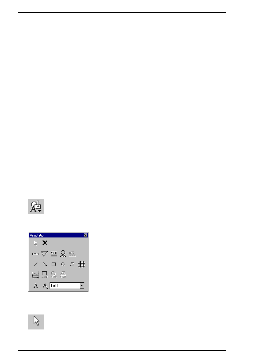
4 Click the Select button.
36
Using the Annotation Software
2272A GB 20001222
Page 37
ANNOTATION SOFTWARE
5 Click the annotation which you wish to edit.
The annotati on is selected. Distance, ang le and calibration annotations consist of a
marker and a label. Reg ion of interest annotations consist of a regi on of interest
marker and a SAL label. You can edit both the markers and the labels.
6 Edit the marker and/or the label:
To Do this
1 Move the pointer to the center of
the item.
Move an item
The pointer is now a cross.
2 Drag the item.
1 Move the pointer to a sizing handle
of the item.
Resize an item
The pointer is now an arrow.
2 Drag the handle.
7 If you have resized a region of interest, right-click it and then click Recalculate
on the shortcut menu.
The scan average level (SAL) is updated.
8 To save the edited annotations, either replace the existing image or save the
changed image as a new image.
Refer to
2272A GB 200012 22
’Saving an annotated image’
on page40.
Using the Annotation Software
37
Page 38
ANNOTATION SOFTWARE
Deleting an annotation
If you wish to definitively remove an annotation, you must delete it.
Once an annotation has been deleted, it can by no me ans be rest ored!
v
If you wish to temporarily hide all annotations, you can turn off
annotations. In that case, the annotations are saved with the image and
can be re-displayed at any time. Refer to ’Showing/hiding annotations’ on
page 10.
To delete one or more annotations:
1 Make the image of which you wish to delete an annotation the active image.
You can click the image either in the thumbnail pane or in the image pane.
2 Turn on annotations.
Refer to
’Showing/hiding an notations’
on page10.
3 On the Tools menu, click Annotation.
Alternatively, you can click the Annotation button on the Standard toolbar.
The Annotation toolbar is displayed.
38
Using the Annotation Software
2272A GB 20001222
Page 39

ANNOTATION SOFTWARE
4 Click the Select button.
5 Click the annotation which you wish to delete.
6 Do one of the following:
• Click the Delete button on the Standard toolbar.
• Click the Delete button on the Annotation toolbar.
• Press the DELETE key.
7 To delete several annotations, repeat steps 4 to 6.
8 To save your modifications, either replace the existing image or save the
changed image as a new image.
Refer to
’Saving an annotated image’
on page40.
2272A GB 200012 22
Using the Annotation Software
39
Page 40

ANNOTATION SOFTWARE
Saving an annotated image
If you have added annotations, and you wish to save these changes, save the
image manually on disk.
To save an image:
1 Make the image the active image.
You can click the image either in the thumbnail pane or in the image pane.
2 Add any annotations.
3 Save the image:
To Do this Button
On the File menu, click
Replace the existing image with the
changed image
Save Image.
Alternat iv ely, you can
click the Save button o n
the Standard toolbar.
Save the changed image as a new
image which is added to the study
The image is stored in the local database.
40
Using the Annotation Software
On the File menu, click
Save as New.
_
2272A GB 20001222
Page 41

ANNOTATION SOFTWARE
2272A GB 200012 22
Using the Annotation Software
41
Page 42

Printed in Belgium
Published by Agfa-Gevaert N.V., B-2640 Mortsel-Belgium
2272A GB 20001222
 Loading...