

Page 1

Aerosoft – Digital Aviation
CRJ-700 CRJ-900
AOM PART 2
Revision Info
VOL
5
5-1-1
26-Jul-2017
Rev #
Date
Author
Change
Version
001
11-Oct-15
IV
Start of documentation
0.90
002
31-Dec-16
MK
Updating to new software
0.92
003
20- Apr-17
MK
Finalizing
1.00
004
01-May-17
MK
Updating to latest files
1.00
On behalf of Authority
Page 2

Aerosoft – Digital Aviation
CRJ-70 & CRJ-900
AOM PART 2
Systems Description
VOL
5
5-1-2
26-Jul-2017
TABLE OF CON TENTS
AUXILLIARY POWER UNIT ..................................................................................................................... 5
AURAL/VISUAL INDICATING & RECORDING .......................................................................................... 6
EICAS CONTROL PANEL ..................................................................................................................... 7
DISPLAY REVERSION .......................................................................................................................... 8
AURAL WARNINGS / AUDIO SIGNALS ............................................................................................... 9
MASTER WARNING LIGHT ................................................................................................................. 9
MASTER CAUTION LIGHT ................................................................................................................ 10
CREW ALERTING SYSTEM (CAS) .................................................................................................. 10
TAKE-OFF WARNING ....................................................................................................................... 13
LANDING CONFIG WARNING .......................................................................................................... 14
MENU PAGE .................................................................................................................................... 15
FLIGHT DATA RECORDER..................................................................................................................... 15
AUTOMATIC FLIGHT CONTROL SYSTEM .............................................................................................. 15
FLIGHT DIRECTOR............................................................................................................................ 16
FLIGHT MODE ANNUNCIATOR – LATERAL MODES .......................................................................... 17
FLIGHT MODE ANNUNCIATOR – VERTICAL MODES ........................................................................ 18
SYNCHRONIZATION ......................................................................................................................... 20
ALTITUDE ALERT SYSTEM .................................................................................................................... 20
AUTOPILOT ......................................................................................................................................... 21
COMMUNICATIONS ............................................................................................................................ 22
AUDIO CONTROL PANEL ................................................................................................................. 22
INTERPHONE AND INTERCOM CONTROL PANEL ............................................................................. 23
RADIO TUNING UNIT (RTU) ............................................................................................................. 23
COMS MENU ................................................................................................................................... 24
TCAS MENU ..................................................................................................................................... 24
BACKUP TUNING UNIT .................................................................................................................... 25
ELECTRICAL ......................................................................................................................................... 25
ALTERNATING CURRENT, AC SYSTEM ............................................................................................. 26
CONTROLS ON OVERHEAD PANEL .............................................................................................. 28
EICAS SYNOPTIC PAGE – HOW TO OPEN AC & DC ELECTRICAL SYNOPTIC PAGES ....................... 29
EICAS SYNOPTIC PAGE – ELECTRICAL POWER SUPPLIED FROM ENGINES ................................... 29
EICAS SYNOPTIC PAGE – ELECTRICAL POWER SUPPLIED FROM AIR DRIVEN GENERATOR .......... 30
EICAS SYNOPTIC PAGE – ELECTRICAL POWER SUPPLIED FROM EXTERNAL POWER .................... 31
EICAS MESSAGES............................................................................................................................. 31
DIRECT CURRENT, DC SYSTEM ........................................................................................................ 32
EICAS MESSAGES ......................................................................................................................... 33
ENVIRONMENTAL CONTROL SYSTEM ................................................................................................. 36
AIR CONDITIONING SYSTEM / PACKS .............................................................................................. 36
ECAM MESSAGES ........................................................................................................................ 37
AVIONICS COOLING SYSTEM ....................................................................................................... 37
ECAM MESSAGES ........................................................................................................................ 38
CABIN PRESSURIZATION SYSTEM .................................................................................................... 38
ECAM MESSAGES ........................................................................................................................ 38
PRESSURIZATION MODES – AUTOMATIC MODES ....................................................................... 40
PRESSURIZATION MODES – MANUAL MODES ............................................................................ 40
SAFETY VALVES ........................................................................................................................... 41
GROUND VALVE .......................................................................................................................... 41
CABIN ALTITUDE LIMIT ................................................................................................................ 41
EMERGENCY DEPRESSURIZATION ............................................................................................... 41
Page 3

Aerosoft – Digital Aviation
CRJ-70 & CRJ-900
AOM PART 2
Systems Description
VOL
5
5-1-3
26-Jul-2017
EMERGENCY EQUIPMENT ................................................................................................................... 42
FIRE PROTECTION ............................................................................................................................... 43
ENGINE FIRE CONTROLS & MESSAGES ............................................................................................ 43
ECAM MESSAGE .......................................................................................................................... 43
APU FIRE CONTROLS & MESSAGES ................................................................................................. 46
CARGO COMPARTMENT FIRE CONTROLS & MESSAGES.................................................................. 46
ECAM MESSAGES ........................................................................................................................ 46
FIRE SYSTEM TEST ........................................................................................................................... 46
MAIN LANDING GEAR OVERHEAT DETECTION ................................................................................ 47
FLIGHT CONTROLS .............................................................................................................................. 48
AILERONS ........................................................................................................................................ 49
RUDDER .......................................................................................................................................... 50
ELEVATOR ....................................................................................................................................... 51
HORIZONTAL STABILIZER TRIM ....................................................................................................... 52
FLAPS AND SLATS ............................................................................................................................ 53
SPOILERS ......................................................................................................................................... 54
STALL PROTECTION SYSTEM ........................................................................................................... 55
FLIGHT INSTRUMENTS ........................................................................................................................ 56
ELECTRONIC FLIGHT INSTRUMENT SYSTEM (EFIS) .......................................................................... 57
DISPLAY REVERSION ........................................................................................................................ 58
DISPLAY CONTROL .......................................................................................................................... 58
AIR DATA SYSTEM ........................................................................................................................... 59
PITOT STATIC SYSTEM ..................................................................................................................... 59
AIR DATA ......................................................................................................................................... 59
AIR DATA REFERENCE (ARP) PANELS ............................................................................................... 60
ALTITUDE ALERTS ............................................................................................................................ 63
LOW SPEED CUE .............................................................................................................................. 63
AIR DATA REVERSION ...................................................................................................................... 63
RADIO ALTIMETER SYSTEM ............................................................................................................. 64
INERTIAL REFERENCE SYSTEM ......................................................................................................... 65
DISPLAY REVERSION .................................................................................................................... 66
STANDBY INSTRUMENTS AND CLOCKS ........................................................................................... 67
INTEGRATED STANDBY INSTRUMENT ......................................................................................... 67
STANDBY COMPASS .................................................................................................................... 68
CLOCKS ........................................................................................................................................ 69
FUEL SYSTEM ...................................................................................................................................... 70
FUEL TANKS / STORAGE .................................................................................................................. 70
FUEL MANAGEMENT (TRANSFER/CROSSFLOW) & DISTRIBUTION .................................................. 70
FUEL QUANTITY GAUGING .............................................................................................................. 72
HYDRAULIC POWER ............................................................................................................................ 74
ICE & RAIN PROTECTION ..................................................................................................................... 77
ICE DETECTION SYSTEM .................................................................................................................. 78
WING AND COWL ANTI-ICE SYSTEM ............................................................................................... 79
AIR DATA ANTI-ICE SYSTEM ............................................................................................................ 80
WINDSHIELD AND SIDE WINDOW ANTI-ICE SYSTEM ...................................................................... 81
WINDSHIELD WIPER SYSTEM .......................................................................................................... 81
LANDING GEAR ................................................................................................................................... 82
BRAKE SYSTEM ................................................................................................................................ 83
PARKING BRAKE .......................................................................................................................... 83
BRAKE TEMPERATURE MONITORING SYSTEM ............................................................................ 84
ANTI-SKID .................................................................................................................................... 85
NOSE WHEEL STEERING SYSTEM ................................................................................................. 86
Page 4

Aerosoft – Digital Aviation
CRJ-70 & CRJ-900
AOM PART 2
Systems Description
VOL
5
5-1-4
26-Jul-2017
LIGHTING ............................................................................................................................................ 87
COCKPIT LIGHTING .......................................................................................................................... 87
PASSENGER COMPARTMENT LIGHTING .......................................................................................... 88
EXTERNAL LIGHTING ....................................................................................................................... 89
EMERGENCY LIGHTING ................................................................................................................... 91
NAVIGATION SYSTEMS ........................................................................................................................ 91
FLIGHT MANAGEMENT SYSTEM (FMS) ........................................................................................... 92
WHERE TO FIND THE FMS/CDU AND BASIC LAYOUT ...................................................................... 92
PREFLIGHT SETUP AND SEQUENCE OF PAGES ................................................................................ 96
GLOBAL POSITIONING SYSTEM (GPS).............................................................................................. 97
VHF NAVIGATION ............................................................................................................................ 97
AUTOMATIC DIRECTION FINDER (ADF) ......................................................................................... 100
DISTANCE MEASURING EQUIPMENT (DME) ................................................................................. 101
AIR TRAFFIC CONTROL TRANSPONDER SYSTEM (ACT) .................................................................. 103
TRAFFIC ALERT AND COLLISION AVOIDANCE SYSTEM (TCAS) ....................................................... 104
TRAFFIC ADVISORY (TA) ............................................................................................................ 106
RESOLUTION ADVISORY (RA) .................................................................................................... 106
AURAL WARNING ...................................................................................................................... 107
GROUND PROXIMITY WARNING SYSTEM (GPWS) ........................................................................ 107
MODE 1 – EXCESSIVE DESCENT RATE ........................................................................................ 109
MODE 2 – EXCESSIVE TERRAIN CLOSURE RATE ......................................................................... 109
MODE 3 – ALTITUDE LOSS AFTER TAKE-OFF ............................................................................. 109
MODE 4 – UNSAFE TERRAIN CLEARANCE .................................................................................. 110
MODE 5 – BELOW GLIDESLOPE ALERT ...................................................................................... 110
MODE 6 – CALLOUTS (DESCENT BELOW MINIMUM, ALTITUDE CALLOUTS AND BANK ANGLE
ALERT) ....................................................................................................................................... 110
MODE 7 –WINDSHEAR DETECTION AND ALERTING .................................................................. 110
TERRAIN / OBSTACLE AWARENESS ALERTING AND DISPLAY .................................................... 112
WEATHER RADAR (WXR) ............................................................................................................... 113
POWER PLANT .................................................................................................................................. 114
THRUST CONTROL ......................................................................................................................... 115
FULL AUTHORITY DIGITAL ELECTRONIC CONTROL (FADEC) .......................................................... 117
FLEX POWER ................................................................................................................................. 118
AUTOMATIC POWER RESERVE (APR) ............................................................................................ 118
HIGH POWER SCHEDULE ........................................................................................................... 119
N1 AND N2 SYNCHRONISATION ..................................................................................................... 119
ENGINE OVERSPEED PROTECTION ................................................................................................ 119
ENGINE N2 INDICATIONS WHEN USING WING ANTI-ICE ............................................................... 119
STARTING AND IGNITION SYSTEM ................................................................................................ 119
OIL SYSTEM ................................................................................................................................... 121
FUEL SYSTEM ................................................................................................................................ 122
INTERTURBINE TEMPERATURE (ITT) MONITORING ...................................................................... 123
VIBRATION MONITORING ............................................................................................................. 123
REVERSE THRUST .......................................................................................................................... 124
PNEUMATICS .................................................................................................................................... 125
Page 5
Aerosoft – Digital Aviation
CRJ-70 & CRJ-900
AOM PART 2
Systems Description
VOL
5
5-1-5
26-Jul-2017
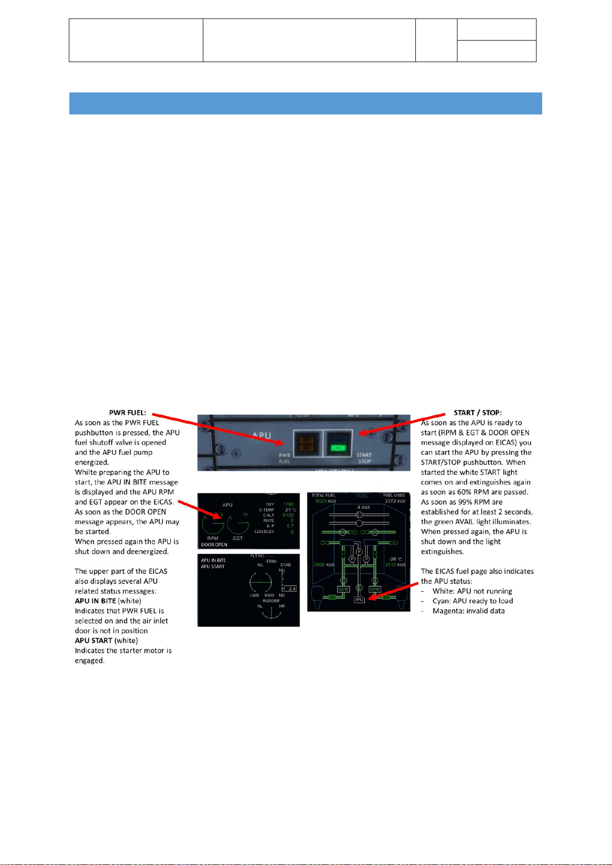
AUXILLIARY POWER UNIT
The CRJ700 and CRJ900 are both equipped with an Allied Signal RE 220 (RJ) auxiliary power unit (APU). The
APU is technically a gas-turbine and it is used to provide electrical power and even more important
compressed air.
The APU is basically comprised of three stages: a compressor followed by a combustion chamber and a
turbine. The APU is started by an electrical motor which rotates the APUs main shaft until it gained enough
speed so that fuel can be injected into the combustion chamber. The fuel burns and hence tries to expand
which accelerates the air even further. The turbine on the other hand drives a generator – so the turbine
converts the accelerated airflow into electrical power. As you can see the basic principle of an APU and an
aircraft engine are technical the same. The major difference is that the APU is not used to produce thrust
therefore APUs are also much smaller than aircraft engines.
Apart from electrical power, bleed air is also drawn from the APU to supply the packs or also the engine
starters (the aircrafts engines are usually started with pneumatic air).
Thus, it is mainly use during aircraft preparation and engine start. Nevertheless, it may also be used as a
backup once an engine failed / was switched off.
The air-inlet-flap of the APU is used to control airflow into the APU. The flaps position is controlled
automatically by the built-in electronics.
Page 6
Aerosoft – Digital Aviation
CRJ-70 & CRJ-900
AOM PART 2
Systems Description
VOL
5
5-1-6
26-Jul-2017
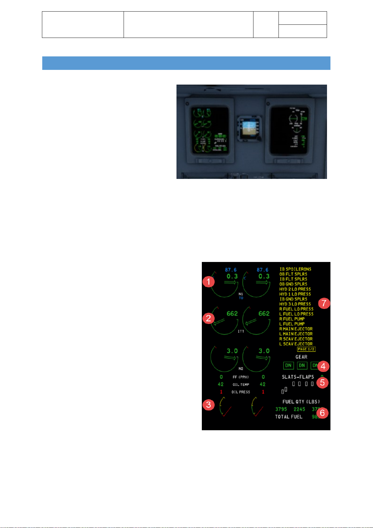
AURAL/VISUAL INDICATING & RECORDING
All aircraft systems do have sensors to detect
abnormal settings or behaviour. All systems –
including the engines – report this information to
two central processing units: the data
concentrator units (1 & 2). The interface to the
pilots is the engine indication and crew alerting
system (EICAS). Certain messages do also trigger
audio signals or trigger the master warning or
master caution light.
The EICAS is comprised of two units – called
EICAS Display 1 & 2 (ED1 and ED2) – basically the
left and the right EICAS display: The left EICAS is called ED1 and the right EICAS ED2.
Normally ED1 displays the primary page and ED2 displays the status page. The EICAS control panel on the
lower pedestal enables the pilots to select if the primary, the secondary or a synoptic page is displayed on
either ED. Please us the display reversion control panels to change whether the primary or secondary is
displayed on ED1 or ED2 respectively. The EICAS source selector panel allows the pilot to select where all EICAS
information is displayed. You may choose between ED1 or ED2 or both (default).
The EICAS primary page displays the following information:
1. Engine compressor and turbine speeds (N1 and N2
rpm)
2. Engine temperature (ITT)
3. Fuel flow (FF)
Oil pressure and temperature
Engine vibration data
4. Landing gear position
5. Slat/flap position
6. Fuel tank quantities and total fuel
7. Crew alerting system (CAS) messages in the form
of red warning and amber caution messages
Page 7
Aerosoft – Digital Aviation
CRJ-70 & CRJ-900
AOM PART 2
Systems Description
VOL
5
5-1-7
26-Jul-2017
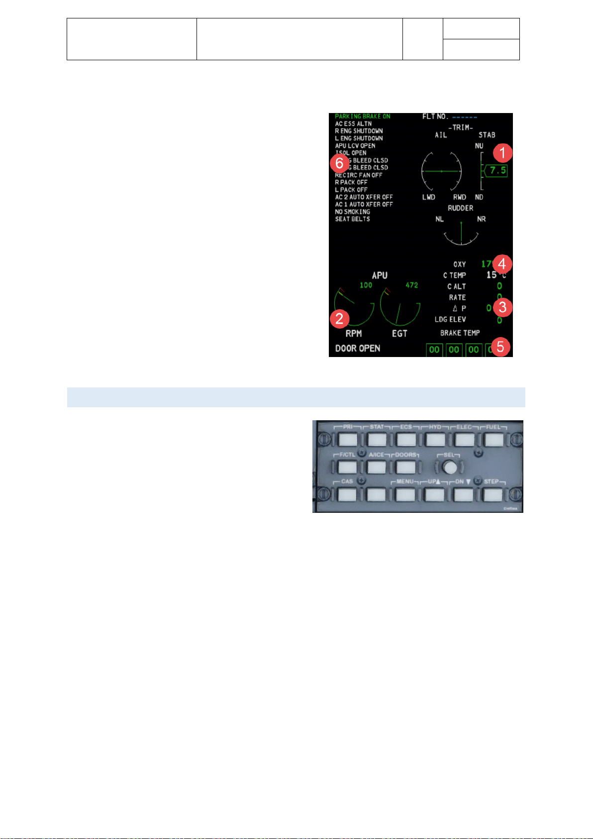
The EICAS status page displays the following information:
1. Flight control trim indications
2. Auxiliary power unit (APU) indications such as APU
RPM, exhaust gas temperature (EGT) and APU inlet
door status
3. Pressurization data such as cabin altitude, cabin rate
of change, cabin pressure differential, and landing
field elevation
4. Oxygen system pressure
5. Brake system temperature readouts
6. Crew alerting system (CAS) messages in the form of
green advisory and white status messages
• Aircraft systems synoptic pages (via the EICAS
control panel)
See next section for more details
• MENU page (via the EICAS control panel) allows
reset of the fuel used indicator and displays the
engine oil quantity
See respective section of this chapter.
EICAS CONTROL PANEL
The EICAS Control Panel enables you to open the
different aircraft system synoptic pages.
The panel itself is found on the upper pedestal. The
following pushbuttons, respective system pages are
available:
• PRI: Opens Primary Page (normally displayed on ED1) on secondary display (ED2)
• STAT: Displays Status Page. A second push removes all status messages / open further status
messages if several pages of status messages exist.
• Synoptic Pages
o ECS: Opens Environmental Control System page
o HYD: Opens Hydraulic system page
o ELEC: Opens Electrical system page
o FUEL: Opens Fuel system page
o F/CTL: Open Flight Controls system page
o A/ICE: Opens Anti-Ice system page
o DOORS: Opens Door system page
o MENU: Opens the menu page
• SEL: Selector – used to activate a selected item. A change in colour will indicate selection
• CAS: Removes caution messages from primary display. Previously invisible messages get displayed
• UP: Controls cursor
• DN: Controls cursor
• STEP: Steps through pages of secondary page if available
Page 8
Aerosoft – Digital Aviation
CRJ-70 & CRJ-900
AOM PART 2
Systems Description
VOL
5
5-1-8
26-Jul-2017
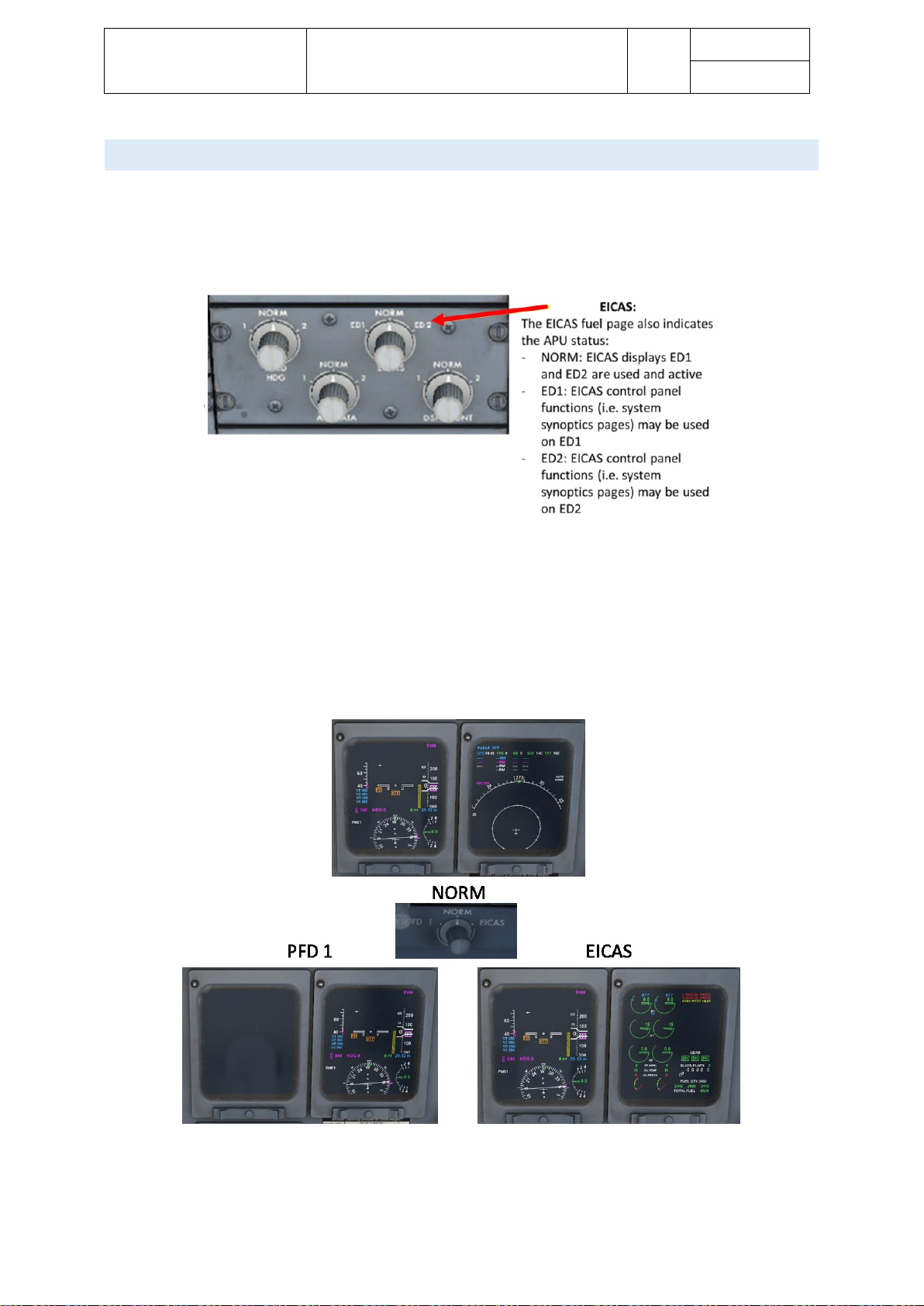
DISP L A Y REVERSION
In case EICAS display ED1 fails, ED2 will automatically switch to primary page. In case EICAS display ED2 fails,
there is no automatic switch. With either display failed, the EICAS control panel is rendered inoperative. Please
switch the EICAS selector on the SOURCE SELECTOR PANEL to the operative display (ED1 or ED2). This reenables you to select and display the EICAS information on the selected display.
Furthermore, a revisionary panel is installed on either pilot’s side panel. They offer three positions:
• PFD 1, respective PFD 2
Switches the respective primary flight display (PFD1 = pilot, PFD 2 = co-pilot) to the adjacent MFD.
• NORM
PFD and MFD in normal operation
• EICAS
Shows the EICAS ED1 display on the MFD.
Page 9
Aerosoft – Digital Aviation
CRJ-70 & CRJ-900
AOM PART 2
Systems Description
VOL
5
5-1-9
26-Jul-2017
AURA L WARNING S / AUDIO SIGNALS
The following table shows the available aural warnings / audio signals.
Sound
Indication
Warbler
Stall
Windshear
Windshear
Whoop – Whoop
GPWS (excessive descent or closure rate)
Fire bell
Fire warnings
Clacker
Excessive stabilizer trim Movement
VMO/MMO exceedance
Airspeed too high for current flap setting
Cavalry Charge
Autopilot disconnect
Horn
Gear warning (not down)
Triple chime
Warning tone (indicates an aircraft system voice advisory)
C-chord
Altitude alert
Single chime
Caution tone (indicates an aircraft system voice advisory)
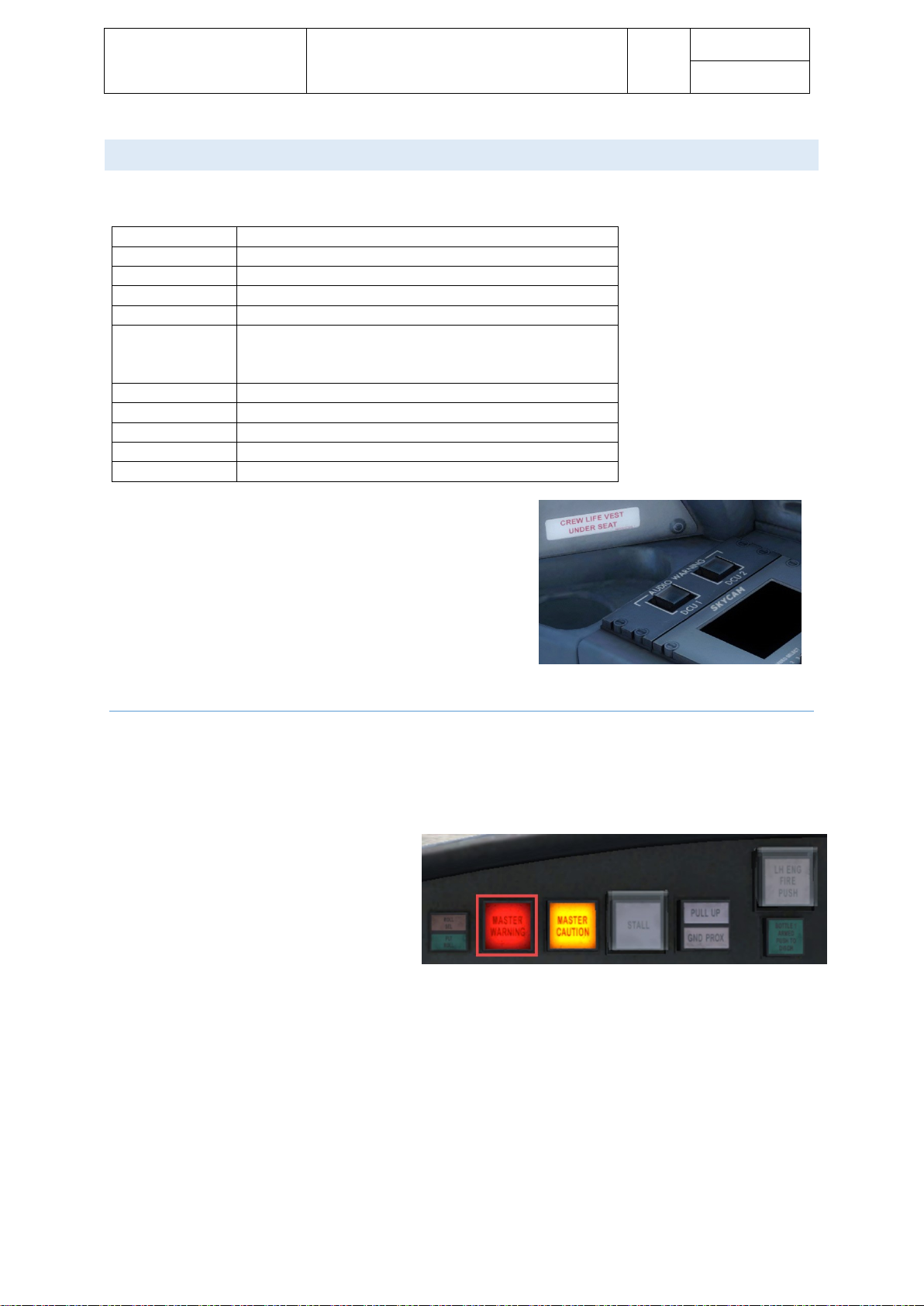
Faulty aural warnings may result from a defective DCU. There are
two guarded pushbuttons on the co-pilots side panel – called the
audio warning panel – to switch off the affected DCU. Open the
guard and press the pushbutton to deactivate the DCU. Switching
a DCU off triggers respective EICAS messages and the pushbutton
will illuminate white.
MASTE R WARNI N G LIGHT
There is a master warning light on either side – the pilot’s and the co-pilot’s side. In case a warning is triggered,
both lights come on and stay flashing if the warning exists or the warning light is pushed by the pilot or copilot. The aural warning and flashing light stay off until the next warning is triggered.
In the following cases the aural warning may
not be muted:
• Stall warbler
• Stabilizer trim clacker
• GPWS/TCAS (voices and aural)
• AP Disconnect cavalry charge
• Overspeed clacker
• Configuration warnings
• Flap clacker
• Gear Horn
Page 10

Aerosoft – Digital Aviation
CRJ-70 & CRJ-900
AOM PART 2
Systems Description
VOL
5
5-1-10
26-Jul-2017
MASTE R CAUTIO N LIGHT
Positioned right next to the master warning
light is the master caution light. It works the
same way the master warning light does.
In the following two cases the master caution
may not be muted:
• GPWS and TCAS voice alerts
• Altitude alert (C-chord) aural
CREW ALERTING SYSTEM ( C AS)
All warning / caution messages are sorted by priority / urgency and order of occurrence. The CAS works with
four categories of messages, with different colour codes and behaviour, indicated in the following table.
In case the triggering condition / fault is removed the message will disappear from the EICAS again. New
messages are added on top according their priority / category.
If the number of message exceeds the available lines in the EICAS, the message “PAGE 1/2” appears in red. All
further messages are available on the following page(s). Press the CAS button to access the messages on the
second side.
When messages are excluded from view by pressing the CAS button a “MSGS” message appears in the EICAS
reminding the crew of the excluded messages. Same goes for advisories and status messages on the STAT
page.
Category
Aural
Warning
Master warning /
master caution
Color
code
Sort order
Displayed
on ED1 /
ED2
Removeable
from EICAS?
Warning
Triple chime
Or voice
Master warning
Red
top
ED1
No
Caution
Single chime
Master caution
amber
Below
warnings
ED1
Yes – CAS
button
Advisory
No
No
Green
Top of ED2
ED2
No – unless
condition is
removed
Status
No
No
White
Below
advisory
ED2
Yes – STAT
button
Page 11

Aerosoft – Digital Aviation
CRJ-70 & CRJ-900
AOM PART 2
Systems Description
VOL
5
5-1-11
26-Jul-2017
To reduce information during flight phases with high stress level, the DCUs filter information:
Inhibit
Inhibit is enabled when:
Inhibit is removed when:
Initial take-off
• Left and right engine N1 is greater than
79%,
• weight-on-wheels, and airspeed is less
than 100 knots.
• Left and right engine N1 is less than
67.6%, or
• Airplane is in the final take-off phase
Final take-off
• Left and right engine N1 is greater
than 79%, and
• airspeed transitions to greater than
100 knots.
• Left and right engine N1 is less than
67.6%, or
• Radio altitude is greater than 400 ft
AGL, or
• 30 seconds after ground to air
transition.
Aircraft System
Warning Message
(Inhibited during take-off)
Aural
(Inhibited during take-off)
Environmental Control
System
CABIN ALT Cabin Pressure
Flight Controls
Overspeed Clacker
Landing Gear
• GEAR DISAGREE
• NOSE DOOR OPEN
• Gear Disagree
• Nose Door
Landing
• Radio altitude transitions to less than
400 ft AGL, and
• landing gear down and locked.
• 30 seconds after air to ground
transition or
• Radio altitude transitions from less
than 400 ft to greater than 400 ft.
Aircraft System
Warning Message
(Inhibited during take-off)
Aural
(Inhibited during take-off)
Auxiliary Power Unit
APU OVERTEMP
APU
Doors
PASSENGER DOOR
Door
Environmental Control
System
• CABIN ALT
• DIFF PRESS
• Cabin Pressure
• Cabin Pressure
Ice and Rain Protection
• ANTI-ICE DUCT
• L COWL A/I DUCT
• R COWL A/I DUCT
• WING OVHT
• Anti-Ice Duct
• Anti-Ice Duct
• Anti-Ice Duct
• Wing Overheat
Landing Gear
NOSE DOOR OPEN
Node Door
Power Plant
• L ENG OIL PRESS
• R ENG OIL PRESS
• Engine Oil
• Engine Oil
Page 12

Aerosoft – Digital Aviation
CRJ-70 & CRJ-900
AOM PART 2
Systems Description
VOL
5
5-1-12
26-Jul-2017
In a similar fashion the cautions are inhibited as well. There are several caution messages which are not
inhibited though:
Airplane system
Caution message (not inhibited)
Automatic Flight Control System
YAW DAMPER
Auxiliary Power Unit
APU LCV CLSD
Fire Protection
FIRE SYS FAULT
Flight Controls
• GLD NOT ARMED
• GLD UNSAFE
• GND SPLR DEPLOY
• IB (OB) FLT SPLRS
• IB (OB) GND SPLRS
• IB (OB) SPOILERONS
• PITCH FEEL
• RUD LIMITER
• SLATS FAIL
• SPOILERONS ROLL
• STAB TRIM
• STAB TRIM LIMIT
• STALL FAIL
Flight Instruments
EFIS COMP MON
Hydraulic Power
HYD 1 (2) (3) LO PRESS
• ICE
• ICE DET FAIL
• L (R) COWL A/I OPEN
• L (R) WING A/I
Landing Gear
• A/SKID INBD (OUTBD)
• IB (OB) BRAKE PRESS
• PROX SYSTEM
• WOW INPUT (OUTPUT)
Pneumatic
• ANTI-ICE DUCT
• L (R) BLEED DUCT
• L (R) COWL LOOP
Power Plant
• L (R) ENG FLAMEOUT
• L (R) ENG SRG CLSD
• L (R) FADEC
• L (R) FADEC OVHT
• L (R) REV INOP
• L (R) REV UNLOCKED
• L (R) REV UNSAFE
Page 13

Aerosoft – Digital Aviation
CRJ-70 & CRJ-900
AOM PART 2
Systems Description
VOL
5
5-1-13
26-Jul-2017
TAKE -OFF WARNI NG
A lot of aircraft do have take-off configuration warning. The actuals aircraft is checked according a
pre-defined logic and in case a deviation is recognized, the crew is informed. The CRJ does this
automatically as soon as the engines are accelerated beyond 70% N1.
The following systems / conditions are checked:
Condition
Voice Message
EICAS Message
Autopilot engaged
Config autopilot
CONFIG AP
Flaps not in take-off position
Config flaps
CONFIG FLAPS
All spoilers not in take-off position
(down)
Config spoilers
CONFIG SPLRS
Horizontal stabilizer outside take-off
range (green band)
Config trim
CONFIG STAB
Parking brake set
Config Brakes
PARKING BRAKE SET
Rudder trim outside of take-off
range (trim > ±1 degree)
Config trim
CONFIG RUDDER
Aileron trim outside of take-off range
(trim > ±1 degree)
Config trim
CONFIG AILERON
If the aircraft detects a deviation it is considered unsafe for take-off. Aural and warning messages
will indicate if such a condition is detected. Furthermore, both MASTER WARNING lights come on.
As soon as the triggering system is corrected, the warning is silenced.
Page 14

Aerosoft – Digital Aviation
CRJ-70 & CRJ-900
AOM PART 2
Systems Description
VOL
5
5-1-14
26-Jul-2017
LANDI NG CONFIG WARNING
Like the take-off configuration the landing configuration is automatically checked, too. A deviation will be
indicated by the landing gear horn. Two minutes after lift-off (ground to air transition) the mechanism is armed
and will sound if one of the following conditions exists:
OR
AND
AND
OR
AND
OR
• Radio altitude < 500 ft
• Both throttles at less than maximum landing setting
OR
• Flaps > 30°
• Both throttles at less than maximum landing setting
OR
• Any one throttle is at IDLE with the landing gear warning horn muted
• Airspeed < 170 kts
• Flaps > 30°
OR
• Airspeed < 190 kts
• Flats / slats = 0
• Radio altimeter OR throttle is not valid
• Radio altitude is less than 1000 ft AGL
• vertical speed less than -400 ft/min
• No windshear warning or a windshear warning with a windshear monitor failure
• Radio altitude is less than 1000 ft AGL
• vertical speed OR GPWS not valid
The “Too low gear” aural warning is heard if:
• any landing gear is not down and locked
• radio altitude less than 500 ft AGL
• indicated airspeed at less than 190 knots.
Page 15
Aerosoft – Digital Aviation
CRJ-70 & CRJ-900
AOM PART 2
Systems Description
VOL
5
5-1-15
26-Jul-2017
MENU PAGE
The MENU page is divided into three sections: menu section, confirmation section and parameter readout. A
cursor on the left side of the screen is controlled by the UP/DN buttons on the EICAS control panel (ECP). The
SELECT button on the ECP is used to select a line item.
The menu list contains a single FUEL USED RESET line. When the line is selected, the ACCEPT/CANCEL
selections in the confirmation section are used to accept or cancel the request to reset to zero the “Fuel Used”
indication, on the FUEL synoptic page.
The parameter readouts section contains the engine OIL LEVEL indications.
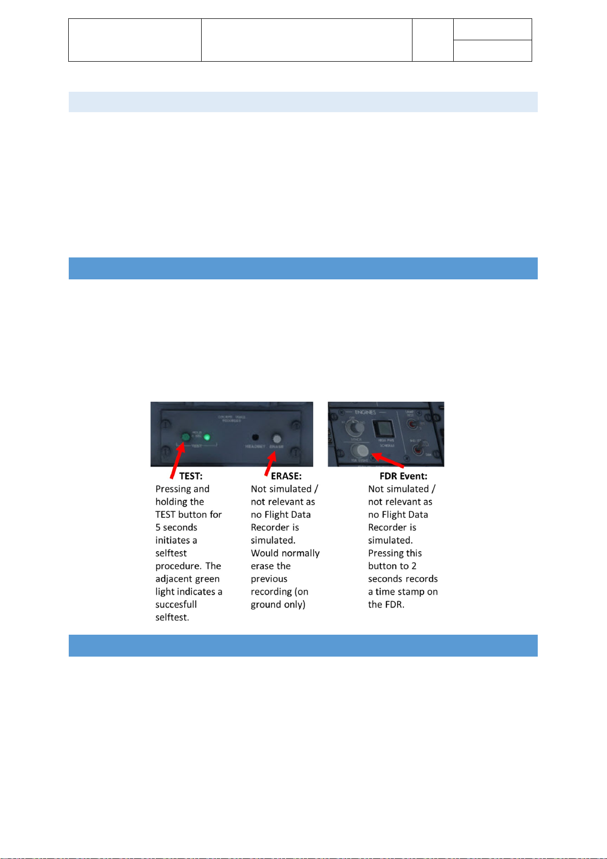
FLIG HT DATA RECORDER
Real aircraft are equipped with flight data and voice recorders. The CRJ’s flight data recorder saves different
information for 25hrs of flight. The FDR automatically starts recording as soon as the BEACON light, STROBE
light is switched ON or a take-off-like condition is detected via the wheels. In case the pilots want to mark a
certain event, they can push the FDR event button for 2 seconds and a timestamp is saved.
The voice recorder saves the last 120 minutes of cockpit communication and passenger announcements as
soon as the aircraft is powered up.
AUTOMATIC FLIGHT CONTROL SYSTEM
The automatic flight control system consists of several systems:
• Flight Director
• Autopilot
• Flight control computers
• Two yaw dampers
• Automatic elevator trim
• Servos / actuators
The flight director computes a flight path which needs to be followed to archive certain pre-set constraints (i.e.
climb at a pre-defined speed to a pre-set altitude). The autopilot computes the required flight control’s
Page 16

Aerosoft – Digital Aviation
CRJ-70 & CRJ-900
AOM PART 2
Systems Description
VOL
5
5-1-16
26-Jul-2017
deflections / trim adjustment to archive the commanded flight path. The flight control computers, FCCs,
calculation are based on data from the inertial reference system and air data computers.
Further input sources are selections made on the flight control panel, flight management computer outputs
and radio system outputs.
FLIG H T DIRECTOR
At this point we like to emphasize the difference between the flight director and the autopilot again. The flight
director indicates the needed attitude to archive a pre-set flight path based on selected mode by means of two
cross-hair bars or a v-shaped indication on the PFD’s attitude direction indicator. The flight director does not
control any actuator, flight controls, engine parameters or such to follow the flight path. It is solely for
indication.
The autopilot on the other hand controls the flight control’s servos and actuators to make the aircraft fly along
the pre-set flight path in accordance with the programmed modes. Basically, the autopilot will do everything
needed to follow the flight director.
Bear in mind that the CRJ has no auto throttle – during take-off, climb and go-around you get help from the
FADEC and fixed throttle detents (see later chapters) but especially during descent and levelling off after
descent you must monitor speed closely and adjust thrust as necessary.
The programmed / selected modes are split up in lateral and vertical modes and are presented on the PFD on
top of the attitude direction indicator. The following section introduces and explains the available modes.
Click the FD pushbutton to activate and deactivate the flight director.
Dave allows you to select different types of flight directors as this
differs between companies.
Page 17

Aerosoft – Digital Aviation
CRJ-70 & CRJ-900
AOM PART 2
Systems Description
VOL
5
5-1-17
26-Jul-2017
FLIG H T MODE AN NUNCIATO R – LATERAL MODES
Mode
Commanded attitude
Annunciation
Select
Cancel
Take-off
mode
On ground: wings level
After lift-off: heading hold
Bank angle ≤ 5°
TOGA button
on thrust
lever
Synchronize FDs
Select different
lateral mode
Navigation
mode
Capture and follow a track to a
navigation source
Nav source
„VOR1/2,
LOC1/2 or
FMS1/2“
illuminates in
green
NAV button
Heading
select
mode
Capture and hold selected heading
Green HDG
message
Push HDG
knob
Select different
lateral mode
Back
course
mode
Capture and hold selected back
course
Green B/C ½
message
Push B/C
switch
Push B/C switch
again or selecting
another lateral
mode
Roll mode
Holds the existing heading. Given
the roll angle upon initiation was
not over 5°
Green ROLL
message
Roll mode is
selected
automatically
if no other
lateral mode
is active
Selecting any
other lateral
mode
Half bank
mode
Reduces maximum bank angle by
50%
White ½ BNK
message
Push ½ BANK
switch or
climbing
through
31,600ft
Pushing ½ BANK
again
Lateral goaround
mode
Heading Hold command, 5° bank
limit, clears all other modes, turns
on both flight directors and turns
off the autopilot
Green GA
message
Press of
TOGA button
on thrust
lever
Selecting
Synchronization
or selecting
another lateral
mode
Approach
mode
Commands to capture and track
the selected navigation source. In
case no valid navigation source is
received, the mode arms but
tracking won’t work. Automatically
selects glideslope mode
Green message
of the used
navigation
source: VOR ½,
LOC ½, FMS ½.
Press APPR
switch.
Press APPR
switch again,
selecting another
lateral mode,
changing nav
source
Page 18

Aerosoft – Digital Aviation
CRJ-70 & CRJ-900
AOM PART 2
Systems Description
VOL
5
5-1-18
26-Jul-2017
FLIG H T MODE AN NUNCIATO R – VERTICAL MODES
Mode
Commanded attitude
Annunciation
Select
Cancel
Vertical
Take-off
mode
Generates a fixed pitch-up
command (pitch angle depends
on take-off speed and difference
between V2 and VR – loss of an
engine reduces commanded
pitch)
clears all other modes, turns on
both flight directors and turns
off the autopilot
Green TO
message
Press of TOGA
button on thrust
lever
Press TOGA switch
again
Engage autopilot
Select
synchronization
Select another
active mode
Pitch
mode
Command to maintain pitch
angle at activation.
Reference value may be altered
using the VS pitch wheel (1/2degree change per click).
When preselecting an altitude –
altitude preselect mode must be
activated before activating pitch
mode
Green PTCH
message
Pitch mode is
automatically
selected when
the flight
director is
activated.
Rotating the VS
pitch wheel also
activates the
pitch mode
(unless in
glideslope
capture or VS
mode)
Selecting a vertical
hold mode
Selecting a vertical
mode capture
Altitude
Hold
mode
Generates commands to
capture and hold selected
altitude.
When the mode is selected, it
sets the current altitude as
reference.
Green ALT
message
Press ALT switch
Press ALT switch
again
Selecting a vertical
hold mode
Vertical mode
capture
Altitude
preselect
mode
Generates commands to
capture and maintain a
preselected altitude. The
preselected value is displayed
on the PFD.
The capture point depends on
the closure rate.
In case the altitude is reselected
during altitude capture (within
200ft of the preselected
altitude), the flight director will
ignore the new setting and
capture the preselected
altitude.
As soon as altitude is captured,
the flight director switches to
altitude hold mode.
Annunciated
by white ALTS
message.
Alt capture is
indicated by
green ALT CAP
message.
It is
automatically
selected as soon
as any vertical
mode (except
glideslope
capture) is
activated.
Cleared by
glideslope capture
or altitude capture
and switching to
altitude hold mode.
Speed
mode
(CLB, DES,
IAS)
Commands pitch in order to
capture and maintain and
preselected airspeed.
Speed is selected by turning the
speed knob.
IAS CLB or IAS
DES
Push the SPEED
knob
Selecting another
vertical capture
mode
Deactivate autopilot
and flight director.
Page 19

Aerosoft – Digital Aviation
CRJ-70 & CRJ-900
AOM PART 2
Systems Description
VOL
5
5-1-19
26-Jul-2017
As soon as the autopilot is
activated or synchronization is
activated the current airspeed is
selected as the reference speed.
Capture of
preselected altitude
automatically
deactivates speed
mode.
Vertical
speed
mode
Generates commands to
maintain and preselected
vertical speed.
The selected vertical speed is
displayed on the PFD and may
be selected in a range of ±
12,000 ft/min using the pitch
wheel.
As soon as the autopilot is
engaged or synchronization
selected, the reference vertical
speed is set to the current
vertical speed.
In case a new altitude is
preselected, the altitude must
be preset before activating VS
mode.
Green
VS #.# or
VS #.#
The #.# shows
the current
vertical speed
in thousands
of feet/minute
Push the VS
switch
Push VS switch
again.
Selecting a different
vertical mode
Capture of
preselected altitude
automatically
deactivates vertical
speed mode.
Glideslope
mode
Generates commands to
capture and follow a glideslope
signal. Capture may be
performed from above and
below the glideslope.
Green GS
message
Glideslope mode
is activated
automatically,
when APR mode
is active, the
aircraft is flying
towards
(inbound) a
navigation
source with a
valid glideslope
signal.
Turning outbound
or dialling in a
different navigation
source, deactivating
APP mode clears
glideslope mode.
Vertical
go-around
mode
Fixed pitch-up command. The
commanded pitch angle
depends on if both engines are
running or one engine is
inoperative.
Activation automatically turns
on both flight directors
disengages both autopilots and
clears all other modes.
The resulting autopilot
disengagement warning sound
may be cancelled by pressing
the TOGA switch again.
Green GA
message
Press TOGA
switch on thrust
lever
Engaging the
autopilot.
Selecting
synchronization.
Selection /
capturing or
another active
mode.
Page 20
Aerosoft – Digital Aviation
CRJ-70 & CRJ-900
AOM PART 2
Systems Description
VOL
5
5-1-20
26-Jul-2017
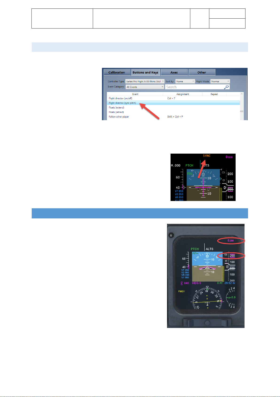
SYNC H RONIZATION
Synchronization enables you to synchronize the flight director bars with the current flight attitude.
The Sync switch on the yoke is
not simulated (because it is
hidden on the backside of the
yoke), so you must use the
standard key assignment “flight
director synchronization”. Please
note this standard key is NOT
assigned in FS/P3D so you must
assign a key to it before it can be used. We used [control]-[shift]-[s].
It has no effect in case the autopilot is engaged and only certain lateral and vertical modes allow
synchronization:
• Lateral
• Bank mode
• Vertical
• IAS mode
• MACH mode
• VS mode
Synchronization is annunciated by an amber SYNC indication on the
PFD. The message disappears after 3 seconds.
ALTITUDE ALERT SYSTEM
The pilots are notified on the PFD in case they are reaching /
leaving a preselected or selected altitude. The respective advisories
are all displayed on the PFD but in two different places:
• The readouts and bugs change colours and state according
the following rules:
• Approx. 1,000ft before reaching a preselected altitude an
aural warning for approx. 1 second is sounded, and the
readout and bugs flash in magenta for approx. 4 seconds
• Within 200ft of the (pre-)selected altitude the readout and
bugs come steady to indicate altitude capture
• In case the aircraft deviates for more than 200ft from the
selected altitude after capture, a 1 second tone will sound
and the readout and altitude bugs will start to flash amber
(and continue if the deviation occurs or the warning is
cancelled by pressing the ALT switch or selecting a
different altitude)
• In case the aircraft is 200ft below the selected altitude the flashing magenta bugs and readout will
cancel
• If the aircraft deviates further (± 1,000ft) from the selected altitude a 1 second tone sounds
• As soon as the aircraft is again within 200ft of the selected altitude the readout and bugs will cease to
flash
Page 21

Aerosoft – Digital Aviation
CRJ-70 & CRJ-900
AOM PART 2
Systems Description
VOL
5
5-1-21
26-Jul-2017
AUTOPILOT
The installed autopilot is a two-axes, digital, fail-passive autopilot. It commands input to the ailerons, elevators
and rudder via the flight control computers, FCCs.
To activate the autopilot the following requirements need to be fulfilled:
• All flight control computers (FCC) are operative
• At least one channel of horizontal trim is available
• At least one yaw damper is engaged
• At least one IRS system is available
• At least one air data computer (ADC) is available
• No significant instability of the aircraft
When flying through turbulent weather autopilot’s corrective signals might reduce passenger comfort. By
selecting the turbulence mode, the intensity of signals is reduced to smooth aircraft motion. Turbulence mode
is automatically cleared as soon as a localizer is captured. The autopilot is activated with the AP ENG
pushbutton and can be deselected by the AP DISC push bar.
The autopilot can also be disengaged by any of the following
controls.
1. Push AP/SP DISC switch on control when – this
equals the autopilot disengage button / key
assignment within FS.
2. Push the AP ENG switch on the flight control panel
3. Lower the AP DISC switch-bar on the right flight control panel
4. Operating the stabilizer trim
5. Pressing the TOGA switch on the thrust levers
6. Disengaging yaw damper by pressing the DISC pushbutton on the yaw damper panel
Disengagement of the autopilot is indicated by an aural warning (cavalry charge) and the AP indications on the
PFDs turns red. After two repetitions of the cavalry charge the warning is cancelled automatically.
Automatic disengagement of the autopilot occurs:
• In case both yaw dampers are disengaged or fail
• In case a failure in the FCC monitoring circuit is detected (not simulated)
• In case a stall warning is triggered
• During a windshear and the subsequent clearance procedure.
It automatically disconnects approx. 2 seconds after the windshear warning
In case the autopilot is disengaged automatically, the following warnings (aural and flashing red AP indication
on the PFD) may be cancelled by pressing the AP/SP DISC switch or either TOGA switch.
Page 22
Aerosoft – Digital Aviation
CRJ-70 & CRJ-900
AOM PART 2
Systems Description
VOL
5
5-1-22
26-Jul-2017
COMMUNICATIONS
Some parts of the communication systems cannot be modelled and are not integrated in this package like the
crew / passenger addressing system, boarding music system, external communication panels, attendant
headsets or similar. So, the communication system basically consists of the
• Audio control panel
• Interphone panel on the centre pedestal
• Intercom control panel
• The radio tuning units
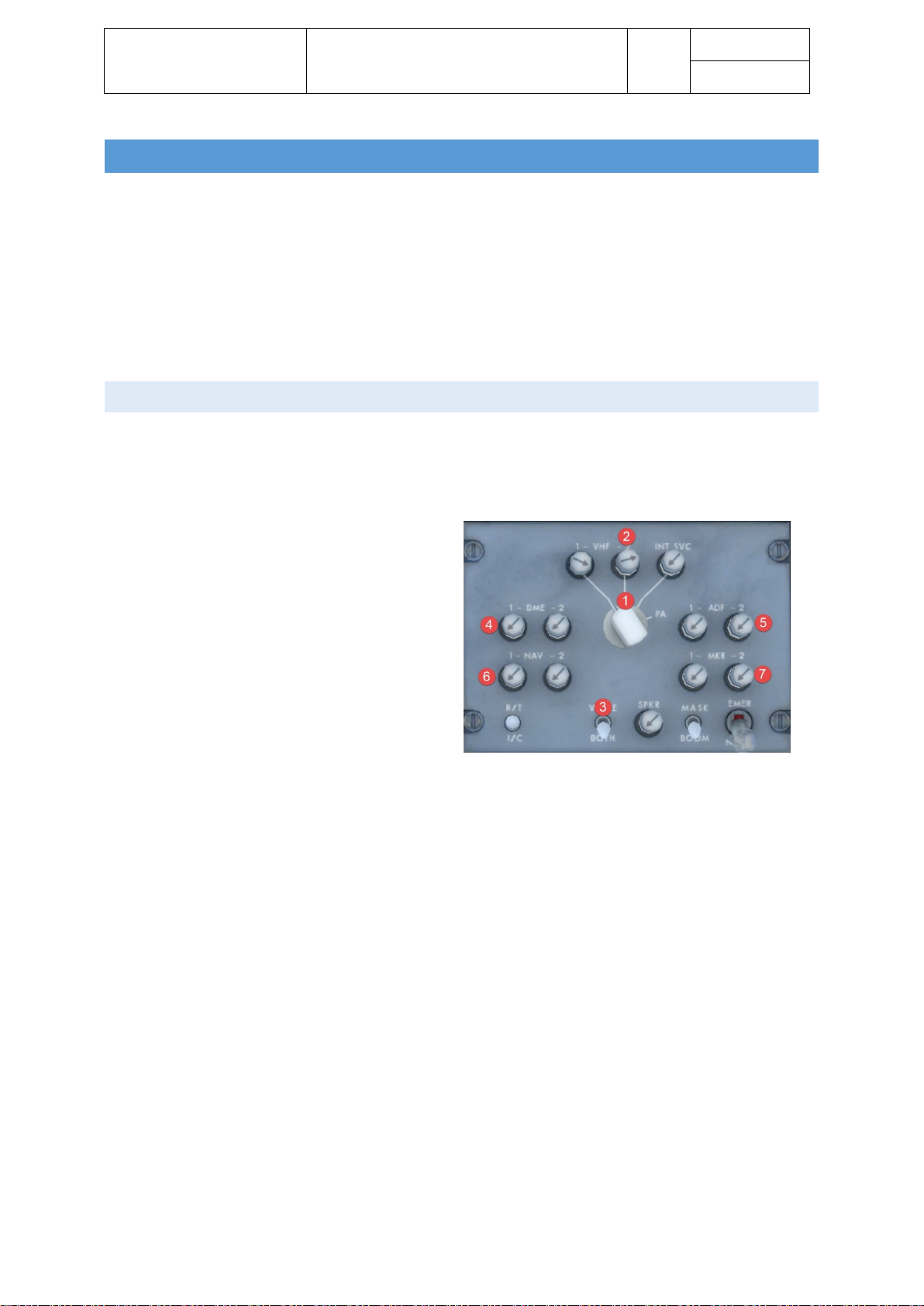
AUDI O CONTROL PANEL
The audio control panel is part of the audio integrating system. The audio integrating system provides display
and control for all incoming and outgoing audio signals of the aircraft’s navigation and communication system.
Three audio control panels are the interface between the crew and the audio integrating system.
1. Transmit Selector: Selects the
communication system, only one can be
active.
2. Receive pushbuttons: Click to select and
deselect.
3. Voice/Both: At voice only the voice
transmissions are audible, at both voice and
station indentification are audible.
4. DME Ident selector: Press to select
5. ADF Ident selector: Press to select
6. NAV Ident selector: Press to select
7. MKR Ident selector: Press to select
The other functions are not simulated.
Page 23
Aerosoft – Digital Aviation
CRJ-70 & CRJ-900
AOM PART 2
Systems Description
VOL
5
5-1-23
26-Jul-2017
INTE RPHONE AND INTERC O M CONTROL PANEL
The interphone panel on the centre pedestal is part of the ground crew
interphone. The ground crew interphone is used to establish
communication between crew in- and outside of the aircraft (like during
pushback, engine start, aircraft maintenance). Hence there are several
panels in and outside the aircraft to establish communication. The interphone panel on the pedestal is the only
one modelled and as the counterparts are missing as outside crew there is no function associated with the
ground crew call button which is normally used to establish communication to an outside crew.
The intercom control panel is used for in-airplanecommunication and it faces similar limitations like the
interphone panel. It is not simulated, on the real plane, it offers
four modes of communication:
• PA: Used to address passengers – turns green when activated / pushed
• CHIME: Sounds a chime in the cabin
• CALL: Sounds a chime in the cabin and enables intercom to the flight attendants – turns green when
activated / pushed
• EMER: Used for emergency calls from the flight deck to the flight attendants – flashed in amber when
activated / pushed
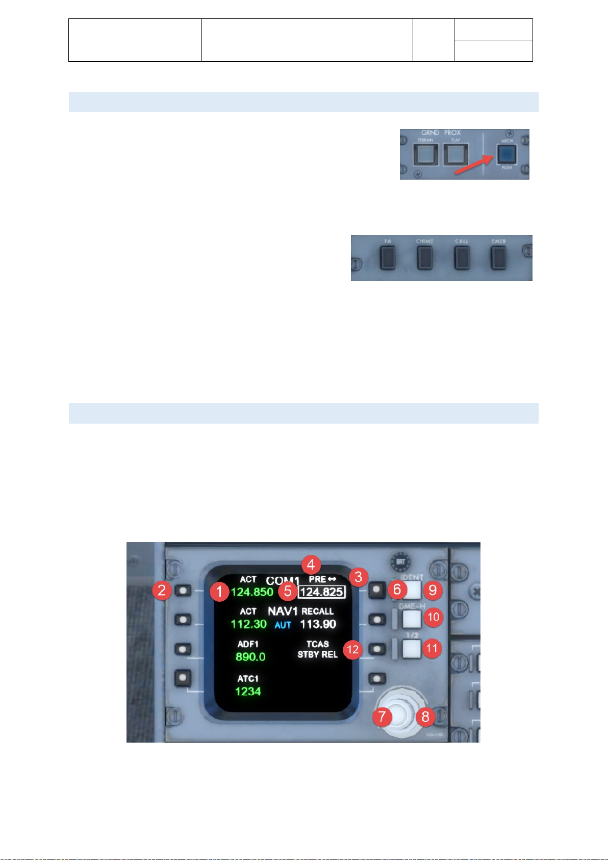
RADI O TUNING UNIT (RTU)
Two VHF (very high frequency) communication systems provide AM (amplitude modulation) voice
communication with ground stations and other aircraft. They operate in a range from 118.000 to 136.975 MHz
They are tuned by via the radio tuning units in normal operation and in case both RTUs fail a backup tuning
unit provides tuning for communication system 1.
The radio tuning units, RTU, are associated with the side they are installed on. Hence the left RTU controls
COM 1 and NAV 1 and the right RTU controls COM 2 and NAV 2.
1. FREQUENCY READOUT: The current active frequency is shown in green
2. SELECT KEY: Push once to directly tune the active frequency, push twice to open COM main page
3. TUNING WINDOW: The while box indicates the frequency that can be adjusted
Page 24
Aerosoft – Digital Aviation
CRJ-70 & CRJ-900
AOM PART 2
Systems Description
VOL
5
5-1-24
26-Jul-2017
4. PRE /RECALL: PRE-indicates the frequency was changed, RECALL indicates the frequency was
swapped with the active frequency
5. PRE-SET FREQUENCY: The Preset frequency (shown in white) can be swapped with the active
frequency
6. FREQUENCY SWAP: Push to swap active with Preset
7. ADJUST FREQUENCY: in 25 kHz steps (COM) or 50 kHz steps (NAV)
8. ADJUST FREQUENCY: in 1 MHz steps
9. IDENT: Sends ATC Ident
10. DME-H: Locks frequency for DME measuring.
11. 1/2: Swaps COM1/NAV1/ADF1 with COM2/NAV2/ADF2
12. TCAS: Push to open TCAS menu
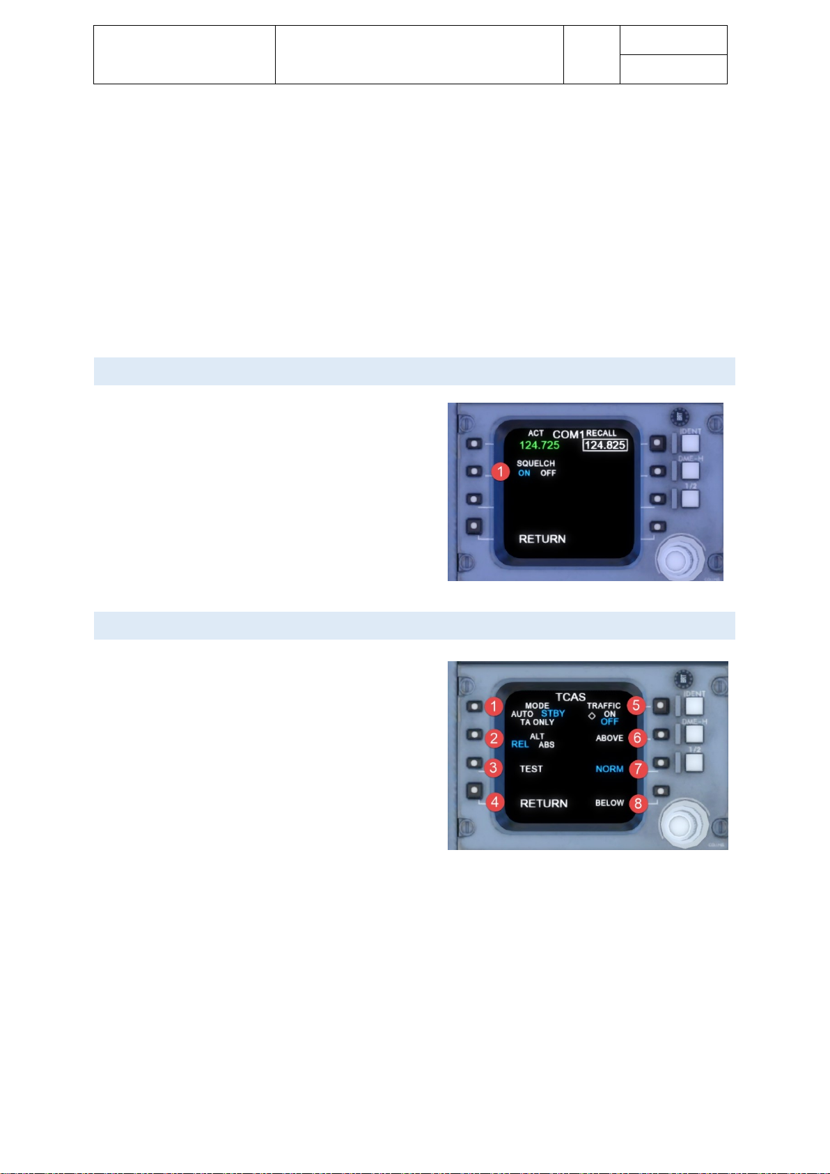
COMS MENU
The COMS menu can be accessed by double clicking the
COM select button (see #2 in previous image). It allows the
toggling of Squelch.
TCAS MENU
The TCAS menu can be opened with the TCAS select
button (see #12).
1. MODE: switch between Auto, Standby and Traffic
Advisory Only
2. ALT: Toggles between relative (difference in
altitude between aircraft and target) or absolute
altitude display
3. TEST: Runs a test program
4. RETURN: back to main RTU menu
5. TRAFFIC: toggles display of traffic symbols on
MDF
6. ABOVE: Shows traffic above altitude (can be selected with BELOW)
7. NORM: Standard display
8. BELOW: Shows traffic below altitude (can be selected with ABOVE)
Page 25
Aerosoft – Digital Aviation
CRJ-70 & CRJ-900
AOM PART 2
Systems Description
VOL
5
5-1-25
26-Jul-2017
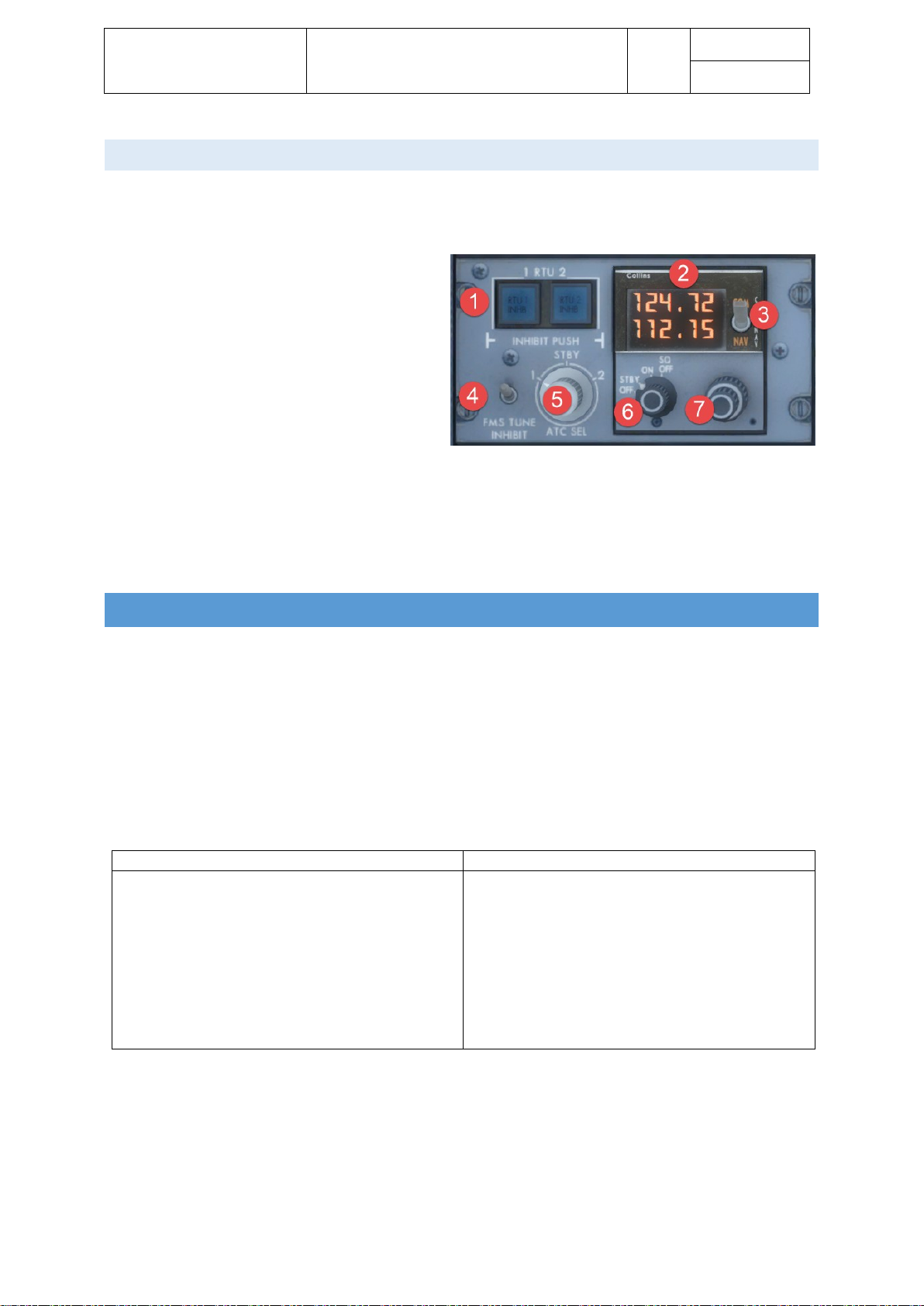
BACKUP TUNING UNIT
The backup tuning unit provides a spare / backup in case both RTUs fail. Normally the backup tuning unit stays
in standby mode the entire flight. As soon as it is switched on it takes control of COM1 and NAV 1.
1. RTU INHIBIT: Disables either RTU
2. FREQUENCY DISPLAY: Shows COM1
(upper) and NAV1) lower, TX is displayed
to indicate transmission
3. TUNING SELECTOR: Toggles between
tuning COM1 and NAV1
4. FMS TUNE INHIBIT: Stops FMS Autotune
function
5. ATC SEL: To select the active transponder
6. MODE SELECTOR:
a. OFF: Display off
b. STB: Displays the frequency shown in RTU1
c. ON: Frequency is controlled by the tuning knob
d. SQ OFF: Squelch selected off
7. TUNING KNOB: To set frequency
ELECTRICAL
The CRJ’s electrical system can be split into an alternating current, AC, subsystem and a direct current, DC,
subsystem. The alternating current, AC system is supplied with power from the engine generators (integrated
drive generators, IDGs), the auxiliary power unit’s generator or the air driven generator, ADG (which is a
backup in case both IDGs fail). The direct current, DC, system is supplied with power from two transformer
rectifier units, TRUs, the main battery, or the APU battery. The TRUs convert alternating current to direct
current. To reload both batteries, battery chargers are installed as well.
Both subsystems use computers to ensure the proper power distribution to the respective systems. The
following table shows the available AC and DC busses.
AC busses
DC busses
• AC BUS 1
• AC BUS 2
• AC ESSENTIAL BUS
• AC SERVICE BUS
• ADG BUS
• DC BUS 1
• DC BUS 2
• DC ESSENTIAL BUS
• DC SERVICE BUS
• DC BATTERY BUS
• DC EMERGENCY BUS
• DC UTILITY BUS
• MAIN BATTERY DIRECT BUS
• APU BATTERY DIRECT BUS
Furthermore – when on ground – an external power receptacle is available which allows the CRJ to be supplied
with ground power. The electrical power panel on the overhead panel is used to control the electrical systems.
Error messages, warning or advisories are indicated on the EICAS.
Page 26
Aerosoft – Digital Aviation
CRJ-70 & CRJ-900
AOM PART 2
Systems Description
VOL
5
5-1-26
26-Jul-2017
ALTE RNATING CURRENT, A C SYSTEM
During normal operation, the IDGs supply alternating current. The APU
may be used as a backup in case both IDGs fail. In case even the APU
fails, the CRJ is equipped with an Air Driven Generator, ADG, which is
basically a propeller which is extended into the airstream. The ADG can
provide enough power for the most important aircraft systems to be
still able to fly the aircraft.
The IDGs are monitored regarding temperatures, oil pressure and
supplied power. In case of exceedances the affected IDG can be
disconnected automatically. Nevertheless, there is also a possibility by
means of a switch light on the electrical power panel, to disconnect the
IDG manually.
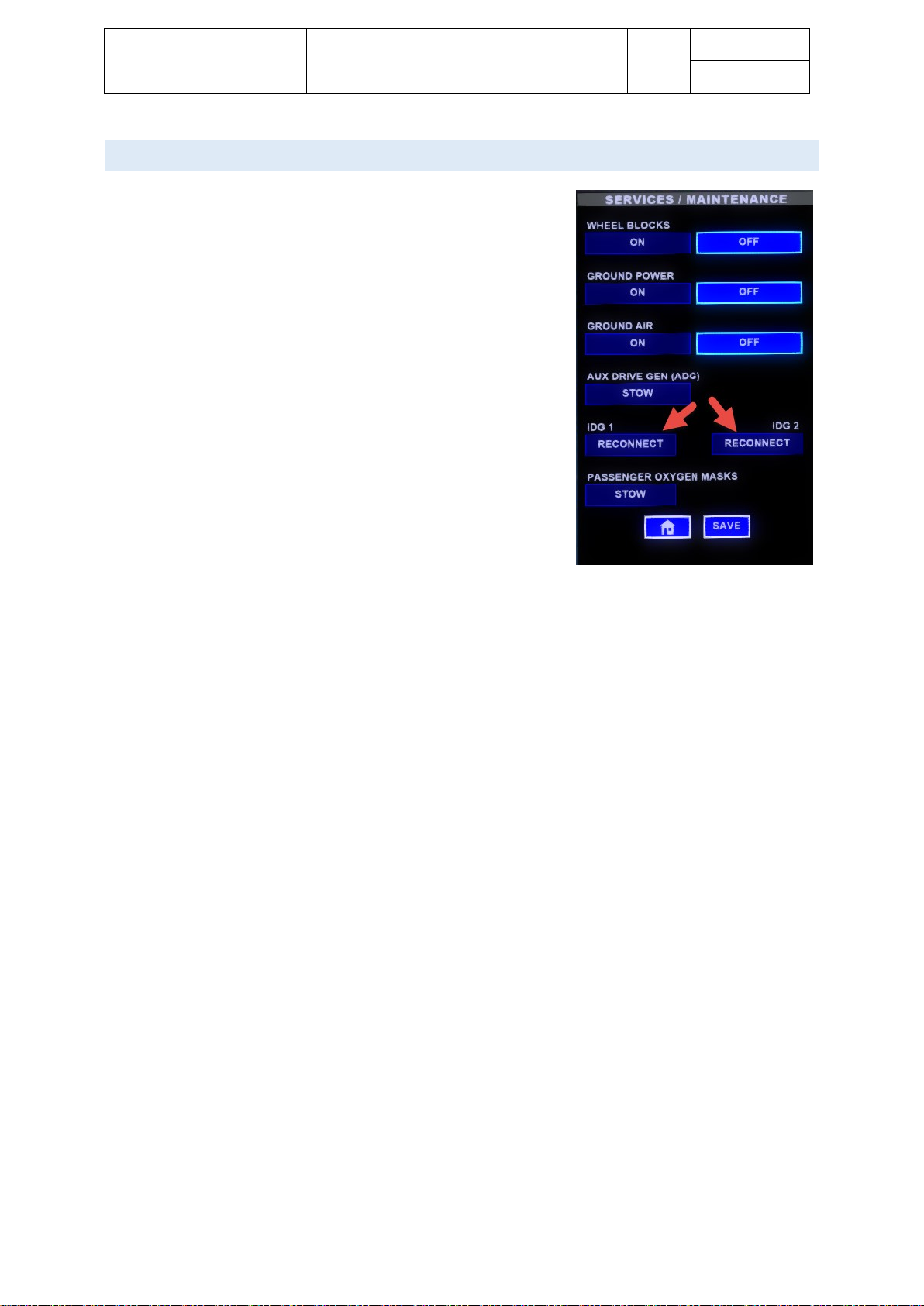
Please bear in mind that a disconnected IDG (no matter if disconnected
automatically or manually) can only be reconnected on ground. Please
open Dave, go to the “Services / Maintenance” page to reconnect the
IDG. Disconnected IDGs are displayed in blue. Press on “Reconnect”
and “Save” to reconnect.
Before disconnecting you may try to reset the IDG by switching the generator switch on the electrical control
panel to OFF/RESET and then back to ON.
Page 27

Aerosoft – Digital Aviation
CRJ-70 & CRJ-900
AOM PART 2
Systems Description
VOL
5
5-1-27
26-Jul-2017
The following table shows the power distribution in the AC system for normal operation:
AC BUS 1
AC BUS 2
AC ESSENTIAL
• Flight Recorder Power
• TRU 1
• Main Battery Charger
• Recirculating Fan 1
• Display Cooling Fan 2
• Lavatory Exhaust Fan
• Baggage Compartment
• Heater
• Slats and Flaps
Channel 1
• Pitch Trim Channel 1
• Hydraulic Pumps 3B
and 2B
• Hydraulic System Fan
• Left Windshield Heater
• TAT Probe Heater
• Right AOA Heater
• Right Pitot Heater
• Enhanced Ground
Proximity
• Warning System
(EGPWS)
• Engine Vibration
Monitor
• Avionics Cooling Fan 2
• ADG Heater
• TRU 2
• Essential TRU 2
• Recirculating Fan 2
• Galley Exhaust Fan
• Galley Heater
• Slats and Flaps
Channel 2
• Pitch Trim Channel 2
• Hydraulic Pumps 3A
and 1B
• Right Windshield
Heaters
• Right Window Heater
• Ice Detector 2
• Co-pilot Panel Integral
Lights
• Inertial Reference Unit
Fan
• Essential TRU 1
• Display Cooling Fan 1
• Avionics Cooling Fan 1
• Crossflow Pump
• Left Pitot Heater
• Standby Pitot Heater
• Left AOA Heater
• Ice Detector 1
• Left Window Heater
• Cabin Ceiling Lighting
• CB Panel Integral Lights
• Pilot Panel Integral Lights
• Overhead Panel Integral
• Lights
• Centre Panel Integral Lights
• Traffic Alert and Collision
• Avoidance System (TCAS)
• Engine Ignition A
AC SERVICE BUS
ADG BUS
• APU Charger
• Logo Lights
• Cabin Sidewall Lighting
• Cabin Ceiling Lighting
• Toilet
• Water System
• Hydraulic Pump 3B
• Pitch Trim 2
• Slats and Flaps #1
• Slats and Flaps #2
Page 28
Aerosoft – Digital Aviation
CRJ-70 & CRJ-900
AOM PART 2
Systems Description
VOL
5
5-1-28
26-Jul-2017
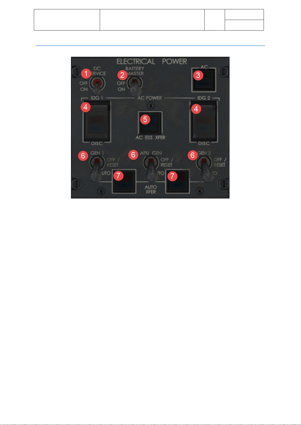
CONTR OLS ON O VERHEAD PANEL
1. DC SERVICE: Connects the DC service bus to the APU battery direct bus
2. BATTER MASTER: Used to supply the battery bus with power from the APU or main direct busses.
Always ON in flight!
3. AC: External Power toggle
- AVAIL indicates connected source
- IN USE indicates AC busses are connected to external power unit
4. IDG1/2 DISCONNECT: Open guard and press push button to disconnect IDG1 (reconnect on ground
only!)
- DISC (white) indicates IDG is disconnected
- FAULT (amber) indicates low oil pressure or high temperature
5. AC ESS XFER: Switches essential bus feed from AC bus 1 to AC bus 2, switches automatic in case of
IDG1 failure
- ALTN (white) indicates essential bus is fed from AC bus 2
6. GEN 1: Used to switch generators between AUTO and OFF
7. AUTO XFER: Disables automatic transfer of respective IDG
- OFF indicates autotransfer is deactivated
- FAIL indicates a fault is preventing autotransfer
Page 29
Aerosoft – Digital Aviation
CRJ-70 & CRJ-900
AOM PART 2
Systems Description
VOL
5
5-1-29
26-Jul-2017
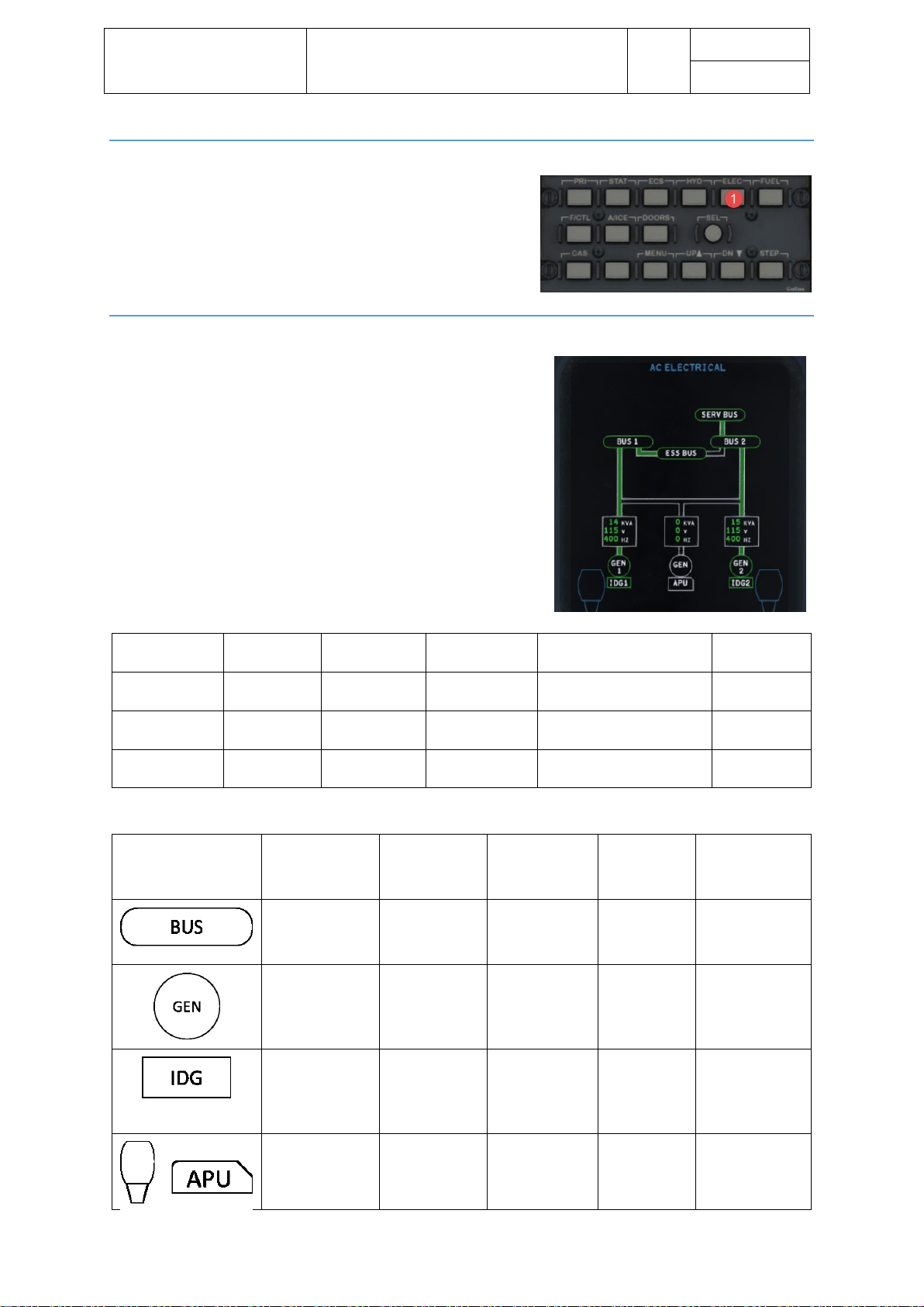
EICAS SYNOPTI C PAGE – HOW TO OPEN AC & DC E LECTRIC A L SYNOPTI C PAGES
The AC and DC electrical synoptic page is opened via the EICAS
control panel by pressing the ELEC key (1) once to open the AC
electrical synoptic page and twice to open the DC electrical
synoptic page.
EICAS SYNOPTI C PAGE – ELE C TRICAL POWER SUPPLIED FROM ENGINES
On the EICAS Electrical displays the green flow lines show energized
busses, white lines show not energized busses.
EICAS DIGITAL
READOUT
GREEN
AMBER
WHITE
HALF INTENSITY AMBER
AMBER
DASHES
XXX kVA
Generator
loaded
Generator
overload
Generator not
loaded
Insufficient data
Invalid data
XXX V
Voltage in
range
-
Voltage not in
range
Insufficient data
Invalid data
XXX HZ
Frequency
in range
-
Frequency not
in range
Insufficient data
Invalid data
EICAS OUTLINE
GREEN
AMBER
WHITE
HALF
INTENSITY
AMBER
HALF
INTENSITY
CYAN
Bus powered
Bus not
powered or
voltage low
-
Invalid data
-
Generator on
Generator off
with engine /
APU running
Both
generator and
engine / APU
are off
Invalid data
-
Constant speed
drive on
Low oil
pressure or
high oil
temperature
Engine is off or
IDG is
disconnected
Invalid data
-
-
-
Engine / APU
off
Invalid data
Engine / APU
running and
ready to load
Page 30
Aerosoft – Digital Aviation
CRJ-70 & CRJ-900
AOM PART 2
Systems Description
VOL
5
5-1-30
26-Jul-2017
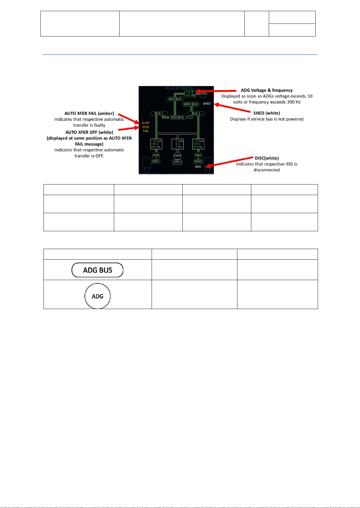
EICAS SYNOPTI C PAGE – ELE C TRICAL POWER SUPPLIED FROM AIR DRI VEN GENER A TOR
EICAS DIGITAL READOUT
GREEN
WHITE
AMBER DASHES
XXX V
Between 108 and 130
volts
Less than 108 or more
than 130 volts
Invalid data
XXX HZ
Between 360 and 440 Hz
Less than 360 or more
than 440 Hz
Invalid data
EICAS OUTLINE
GREEN
WHITE
ADG outline green
ADG outline white
Voltage and frequency digital
readouts green
Voltage or frequency digital
readouts white
Page 31

Aerosoft – Digital Aviation
CRJ-70 & CRJ-900
AOM PART 2
Systems Description
VOL
5
5-1-31
26-Jul-2017
EICAS SYNOPTI C PAGE – ELE C TRICAL POWER SUPPLIED FROM EXTERNA L POWER
Before you can connect an external power supply to your aircraft you need to set the parking brake and/or
chocks and then activate the power cart via Dave. So please open Dave and proceed to the “Services /
Maintenance” menu, then activate the chocks and ground power. Then press SAVE.
The green AVAIL light of the AC pushbutton on the overhead panel
will illuminate as soon as the power supply is connected to the
aircraft. Press pushbutton to accept power supply. Please note that
engines and APU generators need to be off.
1. When External Power is available SERVICE
CONFIGURATION will be displayed
2. When External Power is connected to the busses the
Generator load, Voltage and Frequency will be displayed
EICAS MESSAG ES
For certain occurrences, messages are triggered on the EICAS ED1 and ED2 display.
• IDG 1/2 CAUTION (amber): Low oil pressure or high temperature
• GEN 1/2 CAUTION (amber): Generator(s) off
• GEN 1/2 CAUTION (amber): Generator load over 40 kVA
• APU GEN OFF CAUTION (amber): APU generator ready but off
• APU GEN OVLD CAUTION (amber): APU generator load over 40 kVA
• IDG 1/2 DISC (white): IDG(s) disconnected
• EMER PWR ONLY WARNING (red): ADG deployed
• AC BUS 1/2 CAUTION (amber) : Bus not powered
• AC ESS BUS CAUTION (amber) : AC essential bus voltage under 90 Volts
• AC 1/2 AUTOXFER CAUTION (amber) : Automatic bustransfer failed
• AC 1/2 AUTOXFER OFF (white): Automatic bustransfer deactivated
• AC ESS ALTN (white): Essential bus fed from AC bus 2
• ADG FAIL (white): Generator control unit failed
• ADG AUTO FAIL (white): ADG deployment control unit failed
Page 32
Aerosoft – Digital Aviation
CRJ-70 & CRJ-900
AOM PART 2
Systems Description
VOL
5
5-1-32
26-Jul-2017
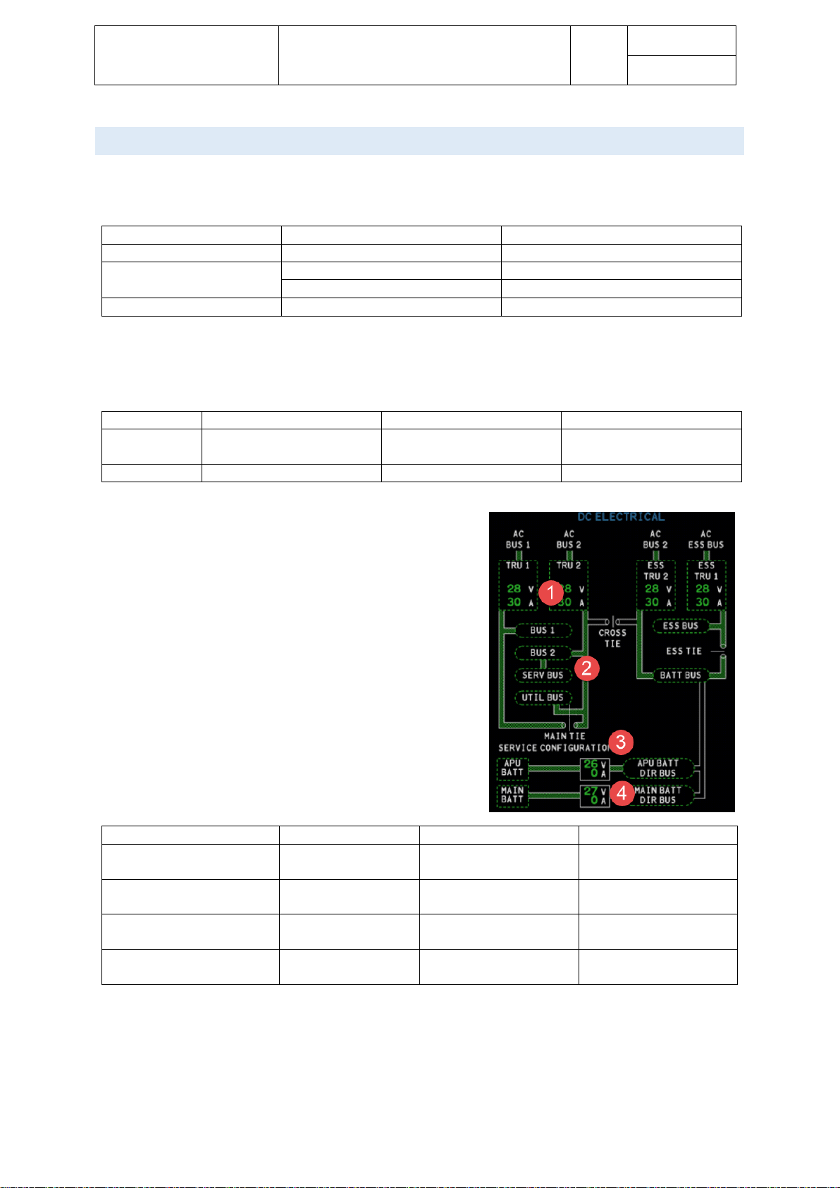
DIREC T CURRENT, DC SYSTEM
Direct power is supplied by four transformer rectifier units, TRUs and two batteries.
The following table shows normal power distribution from the AC to the DC system:
INPUT BUS
TRU
OUTPUT BUS
AC BUS 1
TRU 1
DC BUS 1
AC BUS 2
TRU 2
DC BUS 2 / DC UTILITY BUS
ESSENTIAL TRU 2
DC BATTERY BUS
AC ESSENTIAL BUS
ESSENTIAL TRU 1
DC ESSENTIAL
ESS TRU 2 is normally supplied AC power from AC BUS 2. If AC BUS 2 is not available, ESS TRU 2 will be
automatically supplied from the AC ESS BUS, via the ESS TRU 2 XFR switch.
Battery
location
Output voltage
Capacity
APU
Aft equipment
compartment
24V DC
43 Ah (ampere hours)
MAIN
Nose avionics compartment
24V DC
17 Ah (ampere hours)
1. TRU VOLTAGE / TRU LOAD
2. FLOW LINES: Green indicates bus energized, white
indicates bus not energized
3. SERVICE CONFIGURATION: Indicates DC service is
selected ON
4. BATTERY VOLTAGE / BATTERY LOAD
EICAS DIGITAL READOUT
GREEN
WHITE
AMBER DASHES
XX V (TRU)
Between 22 and 29
volts
Less than 22 volts or
more than 29 volts
Invalid data
XX V (BAT)
Between 18 and 32
volts
Less than 18 volts or
more than 32 volts
Invalid data
XX A (TRU)
Between 3.7 and
120.7 amps
Less than 3.7 amps or
more than 120.7 amps
Invalid data
XX A (BAT)
Between 1.7 or not
less than 12 volts
Less than 1.7 amps and
less than 12 volts
Invalid data
Page 33

Aerosoft – Digital Aviation
CRJ-70 & CRJ-900
AOM PART 2
Systems Description
VOL
5
5-1-33
26-Jul-2017
EICAS OUTLINE
GREEN
AMBER
WHITE
AMBER DASHES
ll
Bus powered
Bus not powered
-
Invalid data
Not less than 18
volts
Less than 18
volts
-
Invalid data
Not less than 3.7
amps and not less
than 18 volts
-
Less than 3.7 amps
and less than 18
volts
Invalid data
Not less than 18
volts
Less than 18
volts
-
Invalid data
EICAS MESSAG E S
For certain occurrences, messages are triggered on the EICAS ED1 and ED2 display.
• APU / MAIN BATT OFF CAUTION (amber): APU or main battery is not available
• DC BUS 1/2 CAUTION (amber): DC bus not powered and AC bus 1 or 2 online
• DC EMER BUS CAUTION (amber): Emergency bus not powered
• DC ESS BUS CAUTION (amber): Essential bus not powered in flight / Essential bus not powered and AC
or APU generator on line on ground
• DC SERV BUS CAUTION (amber): Service bus not powered AND either DC bus 2 OR DC SERVICE is
selected AND APU voltage > 18 volts
• BATTERY BUS CAUTION (amber): Battery bus not powered
• DC CROSS / DC MAIN / DC ESS TIE CLSD (white): Respective bus tie closed
• ESS TRU 2 XFR (white): Displayed when essential TRU 2 is powered by AC essential bus
• APU BAT / MAIN BAT CHGR (white): Battery not charging or overheating
• TRU 1/2 FAIL (white): TRU 1/2 voltage < 18 volt with AC BUS 1/2 online
OR main is closed with TRU 1/2 load < 3.7 amps
• ESS TRU 1/2 FAIL (white): Essential TRU 1/2 voltage < 18 volt with AC BUS 1/2 online
OR main is closed with essential TRU 1/2 load < 3.7 amps
DC BUS 1
Flight Recorder Control
EICAS Primary Display
EICAS Secondary Display
Left Lamp Driver Unit
EICAS Dimming
Data Loader
Left IAPS
Boarding Music
Passenger Door Actuator
ACPC Control 1
Baggage Compartment Control
Fan Monitor
Cabin Pressure Control 1
Cockpit Temperature Sensors
Aft Cabin Temperature Sensors
ACS Control 2 Channel A
Lavatory Smoke Detector
SSCU 1 Channel A
Pitch Feel 1
Radio Altimeter 1
Hydraulic Pump 2 and 3B
Control
Hydraulic System Fan Control
Hydraulic System 2 Indication
Anti-Ice Control Channel A
Left T2 Heater
Pilot Windshield Wiper
Left Windshield Heater Control
ADS Heater Control 2
Right Static Heaters
Brake Pressure Application
PSEU Channel A
Nose Wheel Steering
Anti-Skid
Left Cabin Reading Lights
Cockpit Dome Light
Taxi Lights
Nose Landing Lights
Cockpit Floor Lights
Rear Anti-Collision Lights
Wing Inspection Lights
Maintenance Lights
GPS 1
DME 1
Weather Radar
Page 34

Aerosoft – Digital Aviation
CRJ-70 & CRJ-900
AOM PART 2
Systems Description
VOL
5
5-1-34
26-Jul-2017
DC BUS 2
Right IAPS
Right AFCS
Right IAPS Fan
Observer Audio
VHF Communication 2
RTU 2
Service Bus Feed
ACPC Control 2
Left ACS Pressure Sensors
Cabin Pressure Control 2
Galley Heater Control
Fwd Cabin Temperature Sensors
ACS Control 1 Channel B
Right ACS Manual
SSCU 1 Channel B
Aileron and Rudder Trim
Clock 2
Radio Altimeter 2
Air Data Computer 2
Primary Flight Director 2
Multifunctional Display 2
EFIS Control Panel 2
Attitude Heading 2
Right Fuel Pump and Control
Hydraulic System 1 Indication
Hydraulic Pump 1 and 3A
Control
Right T2 Heater
Copilot Windshield Wiper
Right Windshield Heater Control
Right EFIS CRT Dimming
Right Window Heater Control
PSEU Channel B
Nose Wheel Steering
Brake Pressure Indication
Anti-Skid
Chart Holder Lights
Copilot Map Light
Wing Anti-Collision Lights
ADF 2
Transponder 2
VHF Navigation 2
DME 2
AHRS Fan 2
GPS 2
EMERGENCY BUS
SERVICE BUS
UTILITY BUS
APU Battery Direct Bus Feed
FIREX
Engine and APU Fuel SOVs
Hydraulic SOVs
Service Lights
Boarding Lights
Navigation Lights
Toilet Lights
Galley Area Lights
Beacon Lights
Water System
Right Cabin Reading Lights
ESSENTIAL BUS
EICAS DCU 1
RTU 1
Pilot Audio
Cockpit Voice Recorder
Door Indication 1 and 2
ACS Control 2 Channel B
Left ACS Manual
Display Fan Control
Right ACS Pressure Sensors
Flap and Slat Control Channel 1
SSCU 2
Pitch Feel 2 Rudder Travel Limit
Stall Protection Right Channel
Left EFIS CRT Dimming
EFIS Control Panel 1
Air Data Computer 1
Primary Flight Director 1
Multifunctional Display 1
Crossflow Pump Control
Fuel System Control
Left Static Heater
ADS Heater Control 1
ADS Standby Heater Control
Left Window Heater Control
Anti-Ice Control Channel B
Instrument Flood Lights
Emergency Lights
ADF 1
Transponder 1
VHF Navigation 1
Attitude Heading 1
AHRS Fan 1
Bleed Air SOVs
Thrust Reversers
Right Engine Oil Pressure
Left T2 Heater
Page 35

Aerosoft – Digital Aviation
CRJ-70 & CRJ-900
AOM PART 2
Systems Description
VOL
5
5-1-35
26-Jul-2017
BATTERY BUS
EICAS DCU 1 and 2
EICAS Primary Display
EICAS Secondary Display
EICAS Control Panel
Right Lamp Driver Unit
EICAS Dimming
Left AFCS
MDC
Left IAPS Fan
APU Control
APU ECU Primary
VHF Communication 1
Emergency Tuning
Pilot, Copilot and Observer Audio
Cabin Interphone
Passenger Address
Emergency Bus Feed
IDG Disconnect
Generator Control Units
ACPC Control 3
ADG Deployment
ACS Control 1 Channel A
Ram Air SOV
Manual Cabin Pressure Control
Passenger Oxygen Deployment
Crew Oxygen Monitor
Cargo Smoke Detection
Fire Detection
MLG Bay Overheat Detection
Flap and Slat Control Channel 2
Aileron and Rudder Trim
Indication
Stall Protection Stick Pusher
Stall Protection Left Channel
Standby Instrument
Clock 1
Left Fuel Pump and Control
Fuel System Control
Right T2 Heater
Gravity Fuel Crossflow
Fuel Transfer SOVs
APU Fuel Pump
Hydraulic System 3 Indication
Cowl Anti-Ice Valves
Wing Anti-ice Isolation Valve
PSEU Channel A and B
Weight-On-Wheels
Passenger Signs
Wing Landing Lights
Map Lights
Cabin Utility Lights
Overhead Panel Lights
EICAS and RTU Dimming
Left Engine Oil Pressure
Engine Starting
FADEC
Engine Ignition B
MAIN BATTERY DIRECT BUS
APU BATTERY DIRECT BUS
Main Battery Power Sensors
Main Battery Control
External AC Power
DCPC 2
Main Battery Charger Output
Clocks
Cockpit Dome Lights
APU ECU Secondary
APU Door Actuator
APU Battery Power Sensors
APU Battery Control
DCPC 1
External AC Power
Service Bus Feed
Emergency Bus Feed
Refuel/Defuel Control
Emergency Refuel
Engine Oil Indication
Engine Oil Replenishment
Page 36

Aerosoft – Digital Aviation
CRJ-70 & CRJ-900
AOM PART 2
Systems Description
VOL
5
5-1-36
26-Jul-2017
ENVIRONMENTA L CONTROL SYSTEM
The environmental control system controls mainly the cabin temperature and cabin pressure of the aircraft.
Even though this sounds very simple several different systems are needed to perform these tasks:
• Air condition units / Packs
• Cabin pressurization system
• Recirculation fans
AIR CONDITION I NG SYSTEM / PAC KS
With increasing altitude, the surrounding air gets thinner and colder as well. Above 12,000ft breathing is barely
possible and the air temperature is below freezing point. With aircraft cruising at high altitudes processing the
outside air before letting it enter the cabin is necessary. The air conditioning systems, also called packages, or
packs perform this task by mixing and filtering cabin air and outside air. Hot bleed air from the engines is used
to heat the air from outside before mixing it with the air from the cabin. Bleed air and outside air are not
missed though. In case the engines are not running, bleed air from the auxiliary power unit, APU, may be used
as well.
The CRJ is equipped with two packs. The left pack normally supplies the flight deck and the right pack supplies
the cabin.
1. LEFT (L) / RIGHT (R) PACK:
controls the operation of
the conditioning packs.
2. RECIRCULATION FANS:
controls the recirculation
fans
3. RAM AIR (guarded): Used
when both packs failed to
let ambient air into the left
(cockpit) air condition duct
4. MANUAL MODE VALVE
CONTROL: Directly controls
the valve positions for air
condition in manual mode (cockpit/cabin)
5. MANUAL MODE CONTROL: Selects manual temparature control (cockpit/cabin)
6. AUTOMATIC MODE TEMPERATURE CONTROL: Used to set desired temparature (cockpit/cabin)
7. AFT CARGO BAY AIR CONDITIONING: Activates air conditioning in aft cargo bay. Should be set to
COND after take-off
In case both packs fail and outside air needs to be ventilated into the cabin, you must descend to a suitable
altitude (12,000ft or lower) and activate the RAM air ventilation by pressing the guarded RAM air pushbutton.
OPEN illuminates in white after pressing / activating RAM air ventilation.
To ensure that the air cycles through the cabin, recirculation fans – which are installed in the mixing manifolds
– support cycling. To activate the recirculation fans, move the RECIRC FAN switch to ON.
Page 37

Aerosoft – Digital Aviation
CRJ-70 & CRJ-900
AOM PART 2
Systems Description
VOL
5
5-1-37
26-Jul-2017
1. SELECTED TEMPERATURE (cyan): Indicates the selected
temperature
2. ACTUAL TEMPERATURE (white): Indicates sensed
temperature
3. MANUAL (white): Indicates manual mode is selected.
4. SUPPLY DUCT TEMPERATURE (white): Displays sensed
temperature in the supply duct
ECAM MESSAGES
• HI TEMP (amber): High temperature detected
• AUTOFAIL (amber): Failure or pack in automatic mode is detected
• L/R PACK AUTOFAIL CAUTION (amber): Pack failed in automatic mode and is NOT switched to manual
mode
• L/R PACK TEMP CAUTION (amber): Temperature is > 85 °C
• L/R PACK CAUTION (amber): Pack failed independent of mode (manual / automatic)
• L/R PACK FAULT STATUS (white): Indicates a fault in the pack
• L/R PACK OFF STATUS (white): Indicates pack is switched off
• CKPT /CABIN TEMP MAN STATUS (white): Indicates that manual mode is selected
• RAM AIR STATUS (white): Indicates ram air valve is open.
• AFT CARGO OVHT CAUTION (amber): Temperatures over 40° sensed
• AFT CARGO SOV STATUS (white): Air-inlet shut-off valve failed to open.
AVIONICS COOL I NG SYSTEM
All electrical systems heat up during use. Same goes for all the avionic in the cockpit. Given the restricted
space, cooling is necessary to prevent the avionic from overheating. Two display (DSPLY) fans supply cold air to
the displays – only one of them is running during normal operation: on ground fan 2 and in flight fan 1.
Furthermore, two AVIONIC fans extract the heated air from behind the avionics. On ground fan 2 is powered
and in flight fan 1 is powered.
1. DISPLAY FANS CONTROLS
• GND ALT: Select fan 1
during ground operations
• NORM: Fans in exhaust
duct operate in automatic
mode to exhaust hot air from display and avionics compartments. Fan 1 used in flight, fan 2
used for ground operations
Page 38

Aerosoft – Digital Aviation
CRJ-70 & CRJ-900
AOM PART 2
Systems Description
VOL
5
5-1-38
26-Jul-2017
• FLT ALT: Select fan 2 during flight
• STDB: Selects conditioned air shut-off valve open
2. AVIONICS FANS CONTROLS
• GND ALT: Selects fan 1 during ground operations
• NORM: Fans operate in automatic mode: fan 1 supplies air in flight and fan 2 supplies air
during ground operations
• FLT ALT: Selects fan 2 during flight
ECAM MESSAGES
• OVBD COOL CAUTION (amber): Displayed when overboard exhaust shut-off valve is not closed AND
passengers and service doors are closed. Unable to pressurize in this state.
• DISPLAY COOL CAUTION (amber): Displays when low airflow in cockpit cooling duct is detected.
CABI N PRESSUR I ZATION SYS TEM
Cabin pressure is regulated by controlling the flow of outflowing valve by adjusting the outflow valve’s
position. To limit differential pressure when on ground a ground valve is installed to prevent excessive
differential pressure when on ground.
1. LDG LEVEL: Used to set
destination airport altitude,
selected value displayed on
EICAS
2. MAN ALT: Controls for
pressurization in manual
mode:
• UP: Opens outflow
valve, increase
cabin altitude
• HOLD: All manual selections disabled
• DN: Closes outflow valve, decreases cabin altitude
3. EMER DEPRESS (guarded): Depressurizes airplane in case of emergency, outflow valve is fully opened,
cabin altitude is dumped to 14.500ft
4. PRESS CONTROL: Selects between automatic and manual control
• MAN (white) light indicates manual mode is selected
• FAULT (amber) light indicates a fault of both pressure controllers
• OFF (no light) indicates automatic mode
5. MAN RATE: Adjusts altitude adjustment
• UP RANGE: +150 to +4.000 fpm
• DN RANGE: -100 to -2.500 fpm
ECAM MESSAGES
• CABIN ALT WARNING (red): Cabin altitude exceeds 10.000ft
• DIFF PRES WARNING (red): Differential pressure exceeds 8.6 PSI
• AUTO PRESS CAUTION (amber): Automatic pressurization control is unserviceable
• CABIN ALT CAUTION (amber): Cabin altitude between 8.500 and 10.000ft
• EMER DEPRESS CAUTION (amber): Emergency decompression activated
Page 39
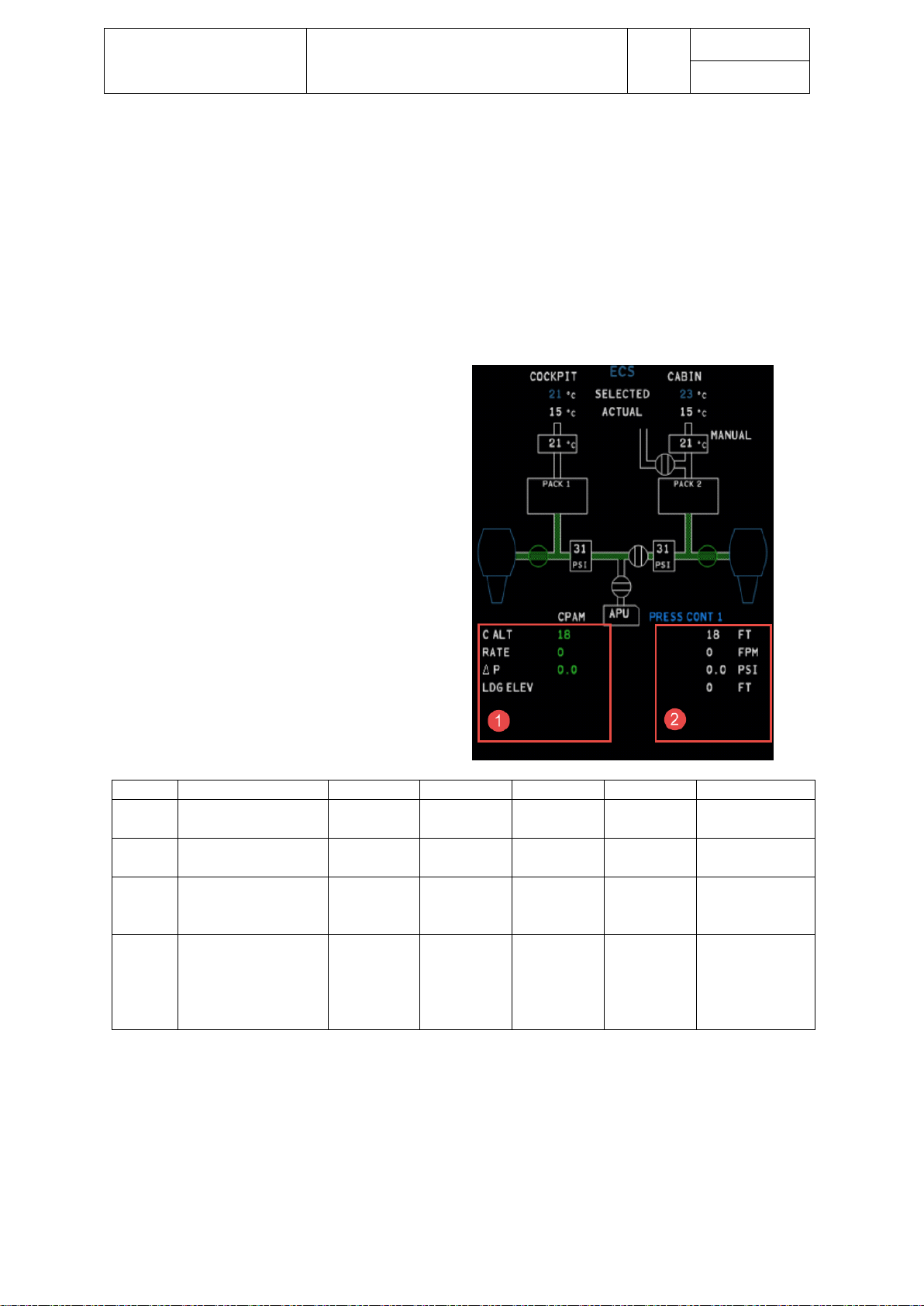
Aerosoft – Digital Aviation
CRJ-70 & CRJ-900
AOM PART 2
Systems Description
VOL
5
5-1-39
26-Jul-2017
• ALT LIMITER CAUTION (amber): Altitude limitation function unserviceable
• OVDB COOL CAUTION (AMBER): Ground valve open in flight
• AUTO PRESS 1/2 FAIL STATUS (white): Cabin pressure control unserviceable
• AUTO PRS 1/2 FAIL STATUS (white): Active channel is lost in manual mode
• CABIN PRESS MAN STATUS (white): Landing elevation set above 8.000ft
• CPAM FAIL STATUS (white): Ground valve has closed on ground
• OUTFLOW VLV OPEN STATUS (white): Outflow valve in fully open position
1. MONITORED DATA
2. ACTIVE DATA
Item
Description
Green font
White font
Amber font
Red font
Amber dashes
C ALT
Cabin altitude in
100ft increments
Monitored
data
Active data
> 8.500ft
> 10.000ft
Invalid data
RATE
Rate of climb of
cabin altitude
Monitored
data
Active data
- - Invalid data
DELTA
P
Differential pressure
between ambient
and cabin pressure
Monitored
data
Active data
-
> 8.6PSI
Invalid data
LDG
ELEV
Selected landing
field elevation in
20ft increments.
Displayed in cyan
Invalid data,
elevations
above 15.000ft
and below
-2.000ft
Two cabin pressure controllers are available to regulate cabin pressure. Only one cabin pressure controller is
active at a time – the other one is on standby but automatically updates the status of the cabin pressurization
system. The pressure controller will automatically adjust the outflow valves position to maintain a differential
pressure of 8.3 PSI.
Page 40

Aerosoft – Digital Aviation
CRJ-70 & CRJ-900
AOM PART 2
Systems Description
VOL
5
5-1-40
26-Jul-2017
The following table shows typical cabin altitude in relation to the aircrafts altitude.
Aircraft altitude (feet)
Cabin altitude (feet)
10‘000
-200
15’000
600
20’000
1’500
25’000
2’700
30’000
4’200
35’000
6’000
41’000
8’000
PRES S U RIZATI O N MODES – AU TOMATIC MODES
Mode
Trigger
Behaviour
Ground mode
A/C on ground
Outflow valve & ground valve → full open
Pre-pressure mode
(Packs ON)
Thrust levers advanced to take-off
Cabin climb rate = 300 ft./min, limited at a
diff. pressure of 150 ft./min
Pre-pressure mode
(Packs OFF)
Thrust levers advanced to take-off
Outflow valve and ground valve closed
Take-off abort
mode
Thrust-levers retarded to idle
Cabin ascends for 20 seconds at approx. 500
ft./Min, then outflow valve full open
Climb mode
Fixed schedule cabin alt. vs. aircraft alt.
Climb rates 500 to 800ft/min dependant on
the aircrafts rate of climb
Flight abort mode
Aircraft maintained altitude 6’000ft
above take-off field elevation for 10
minutes and has initiated descend of
1’000ft/min
System assumes landing elevation
regardless of pre-selected landing elevation
Descent mode
descent
Cabin rate of descent approx. 300 to 700
ft/min to either landing field elevation or
maximum differential.
In case the landing field elevation is higher
than 8’000ft, cabin altitude will be
maintained at maximum differential, until
the airplane descends, then the cabin
altitude will rate up to the pre-selected
landing elevation.
Landing mode
The cabin altitude is driven below field
elevation or the airplane is
unpressurized
When the cabin is below field elevation,
then the cabin is rated up at approximately
600 ft/min for 30 seconds, then the outflow
valve is driven full open
Touch and Go
mode
Landing mode activated and thrust
levers are advanced
System will switch to pre-pressure mode
PRES S U RIZATI O N MODES – M A NUAL MOD ES
Caution: In manual mode, you must manually select HOLD mode as soon as the required altitude is reached
Mode
Trigger
Behaviour
UP Cabin ascends at selected rate of 150 (±150)
to 3,000 (±500) fpm
DN Cabin descends at selected rate -100 (±100)
to -2,500 (±500) fpm
HOLD
Disables all previous MAN ALT selections
Page 41

Aerosoft – Digital Aviation
CRJ-70 & CRJ-900
AOM PART 2
Systems Description
VOL
5
5-1-41
26-Jul-2017
SAFET Y VALVES
Two safety valves prevent the differential pressure exceeding its maximum.
• Maximum positive differential pressure limit 8.6 PSI (tolerance ±0.1PSI)
• Maximum negative differential pressure limit -0.5 PSI
GROUND VALVE
On ground the ground valve is normally open if passenger and/or service doors are open. The valve limits
differential pressure drop due to discharging air from the avionics cooling. As soon as the passenger and
service doors are closed and locked, or the pre-pressurization mode is initiated, the valve is driven to the
CLOSED position.
In case the ground valve fails to open on ground an OVBD COOL FAIL status message appears on the EICAS
status page.
CABI N ALTITUD E LIMIT
To prevent an increase of cabin altitude after passing 14’500 ft. (±500 feet) with the aircraft, the outflow valve
closes automatically.
EMER G ENCY DEP R ESSURIZA TION
As soon as the EMER DEPRESS pushbutton is pressed, the outflow valve is driven open. In case the aircraft
cruises at a higher altitude, the altitude limiter will limit cabin al to 15’000ft.
Page 42

Aerosoft – Digital Aviation
CRJ-70 & CRJ-900
AOM PART 2
Systems Description
VOL
5
5-1-42
26-Jul-2017
EMERGENCY EQUIPMENT
As most parts of the emergency equipment are hardware, there is not much to simulate within FS. You’ll find
four parts of the emergency equipment which are represented but without further function:
1. The oxygen masks on the pilots and co-pilots side, click to hear test the flow of oxygen
2. The PASS OXY switch on the overhead panel: Activates the oxygen supply for the passengers – not
simulated obviously
3. The Emergency Locator Transmitter, ELT, switch.
It is located on the overhead panel as well. It has two positions: ARM/RESET which is the usual
position and ON. The ELT normally activates automatically as soon as a crash is detected.
Nevertheless, this detection may be overridden by setting the switch to ON. The ELT sends a location
signal as soon as activated to ease search and rescue crews finding the aircraft.
4. Skycam: After 9/11 authorities and manufacturers developed concepts to prevent other people than
the flight crew from entering the cockpit in flight. Hence a reinforced and bulletproof cockpit door
was developed which is supposed to stay locked throughout the flight. As the need to leave and enter
the cockpit can’t be prevented, a camera system was installed so pilots can check certain spots in the
cabin via cameras and a display unit in the cockpit. This unit is represented In the CRJ’s cockpit even
though only static pictures are called when cycling through the Skycam-views.
Page 43

Aerosoft – Digital Aviation
CRJ-70 & CRJ-900
AOM PART 2
Systems Description
VOL
5
5-1-43
26-Jul-2017
FIRE PROTECTION
The following aircraft components are protected by the fire detection and protection system:
• Engines
• Auxiliary power unit, APU
• Forward and aft cargo compartment
• Main wheel well
• Lavatories
Fire detection is indicated by aural and visual warnings as well as EICAS warnings.
The engines, APU, forward and aft cargo compartment are monitored by the same fire detection and
extinguishing system (called FIDEEX).
Fire loops, installed in the engines and the APU, indicate a fire and trigger the respective fire warning. To
extinguish a fire, the engines are equipped with two FIREX bottles. Each bottle contains two squibs of halon
which is injected with 600 PSI into the engine when triggered by the pilot. There is another bottle with just one
squib for extinguishing APU fires.
ENG I NE FIRE CONTROLS & M ESSAGES
On the pilot’s side, only the left engine fire controls are available, the right hand of the glare shield there are
controls for both engines (shown here)
1. LH/RH FIRE PUSH: Red light
indicates a fire was detected. Press
to isolate the engine from the fuel
transfer, hydraulic, bleed air
systems. This results in an engine
shut down.
2. BOTTLE 1/2 DISCHARGE: Press to
discharge, green light indicates the
squib is armed and bottle is
charged.
ECAM MESSAGE
• L/R ENG FIRE WARNING (red): Engine fire detected
• L/R ENG SQB CAUTION (amber): Appears when either or both bottles have fired or have failed
• L/R FIRE FAIL CAUTION (amber): Indicates a failure in either fire detection system
• ENG BTL1/2 CAUTION (amber): Indicates respective bottle was discharged
• L/R ENG SQB STATUS (white): Appears when either or both bottles have fired or have failed
Page 44
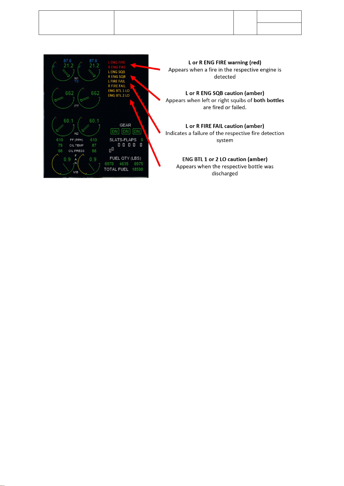
Aerosoft – Digital Aviation
CRJ-70 & CRJ-900
AOM PART 2
Systems Description
VOL
5
5-1-44
26-Jul-2017
Page 45

Aerosoft – Digital Aviation
CRJ-70 & CRJ-900
AOM PART 2
Systems Description
VOL
5
5-1-45
26-Jul-2017
ENGINE FIRE EXTINGUISHING
EVENT
(Left engine fire
procedure is described;
the right engine fire
procedure is similar)
RESULT
GLARESHIELD INDICATIONS
LH ENG
FIRE
PUSH
BOTTLE 1
ARMED
PUSH TO
DISCH
BOTTLE 2
ARMED
PUSH TO
DISCH
MASTER
WARNING
1
Fire condition
occurs in the left
engine fire zone
Fire bell sounds
MASTER WARNING
LH FIRE PUSH switch lights come on
ON OUT
OUT ON
2
MASTER WARNING
switch light is
pressed in.
Fire bell is silenced
MASTER WARNING switch out
System is reset
ON OUT
OUT OUT
3
Left thrust lever is
set to the SHUTOFF
position
LH ENG FIRE PUSH
switch light remains on
ON OUT
OUT OUT
4
LH ENG FIRE PUSH
switch light is
pressed in
BOTTLE 1 ARMED PUSH
TO DISCH switch light comes on
BOTTLE 2 ARMED PUSH
TO DISCH switch light comes on
Left squibs of bottles 1 and 2 armed
Left engine fuel SOV closes
Left bleed air SOV closes
Left hydraulic SOV closes
ON
ON
ON
OUT
5
BOTTLE 1 ARMED
PUSH TO DISCH
switch light is
pressed in
Left squib on bottle 1 fires
FIREX agent from bottle 1 discharges
into left power plant nacelle
ON ON ON OUT
6
Bottle 1 fully
discharges
The pressure switch on bottle 1 opens
as pressure drops below the set point
ENG BTL 1 LO is displayed on the EICAS
ON OUT
ON OUT
7
Fire condition in left
engine persists
LH ENG FIRE PUSH
switch light remains on
ON
OUT
ON
OUT
8
BOTTLE 2 ARMED
PUSH TO DISCH
switch light is
pressed in
Left squib on bottle 2 fires
FIREX agent from bottle 2 discharges
into left engine nacelle
ON OUT
ON OUT
9
Bottle 2 fully
discharges
The pressure switch on bottle 2 opens
as pressure drops below the set point
ENG BTL 2 LO is displayed on EICAS
OUT OUT
OUT OUT
Page 46
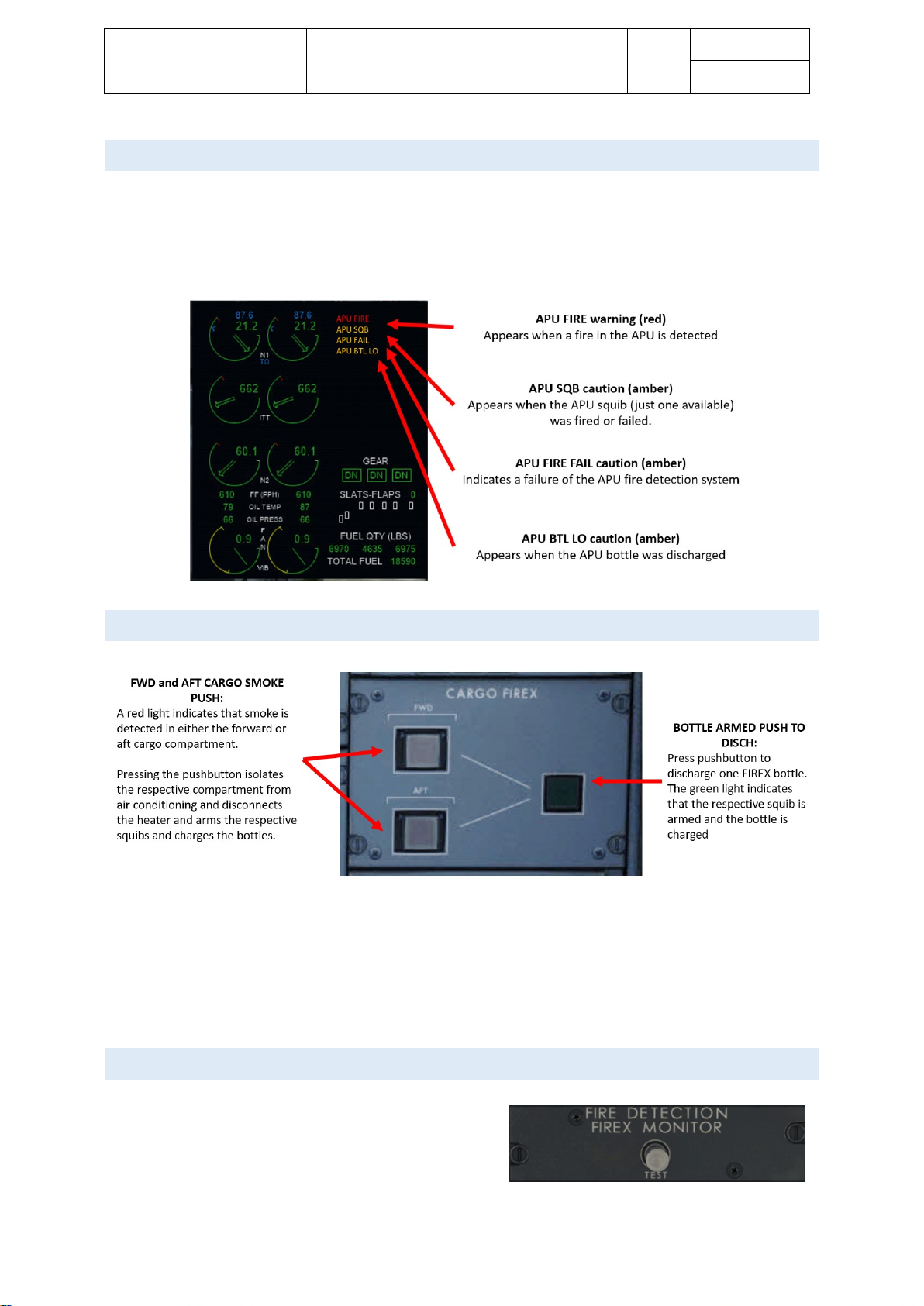
Aerosoft – Digital Aviation
CRJ-70 & CRJ-900
AOM PART 2
Systems Description
VOL
5
5-1-46
26-Jul-2017
APU FIRE CONTROLS & M E S SAGES
• APU FIRE WARNING (red): Appears when APU fire is detected
• APU SQB CAUTION (amber): Appears when APU squib was fired or failed
• APU FIRE FAIL CAUTION (amber): Indicates a failure of the APU fire detection system
• APU BTL LO CAUTION (amber): indicates APU bottle was discharged
CARG O COMPARTM ENT FIRE CONTROLS & MESSAG ES
ECAM MESSAGES
• SMOKE AFT / FWD WARNING (red): Smoke in aft/forward cargo area detected
• AFT / FWD CARGO SQB 1/2 CAUTION (amber): Respective squib was fired or failed
• AFT / FWD CARGO DET CAUTION (amber): Failure of fire detection system
• APU BTL LO CAUTION (amber): One or both bottles discharged
FIRE S YSTEM TES T
Pressing and releasing the FIRE DETECTION test button will
initiate a test sequence. The engine fire controls will light up
and FIRE SYS OK will show on EICAM to indicate a successful
test.
Page 47

Aerosoft – Digital Aviation
CRJ-70 & CRJ-900
AOM PART 2
Systems Description
VOL
5
5-1-47
26-Jul-2017
MAIN LANDING G EAR OVER HEAT DETE C TION
1. MLG BAY OVHT: Tests the landing gear overheat detection
system. Will show MLG OVHT FAIL CAUTION (red) in
EICAM and will light MASTER WARNING light
2. MLG OVHT FAIL: Used to simulate a failure in the landing
gear bay overheat detection. Will show MLG OVHT FAIL
WARNING (amber) in EICAM and will light MASTER
CAUTION light
Page 48
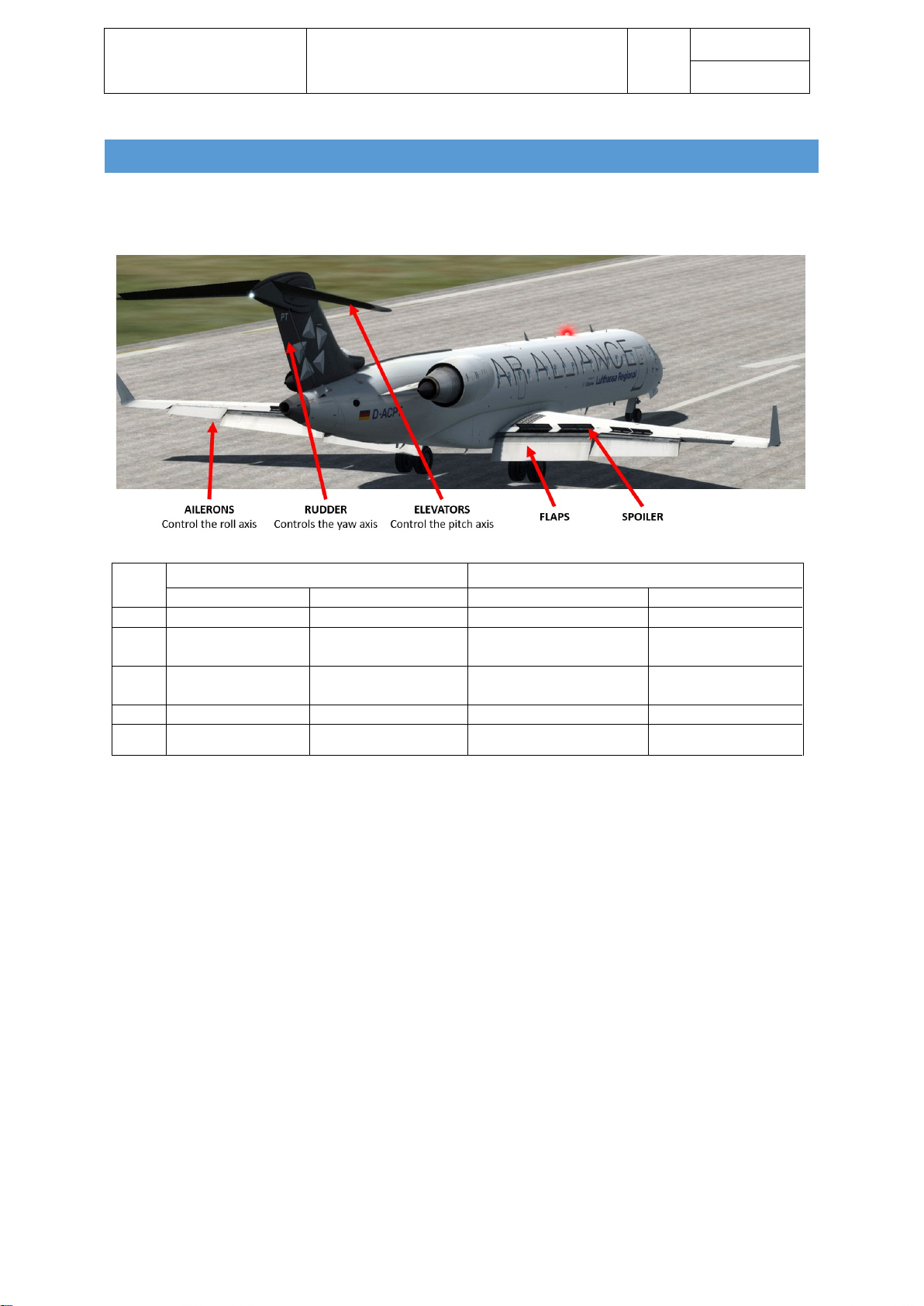
Aerosoft – Digital Aviation
CRJ-70 & CRJ-900
AOM PART 2
Systems Description
VOL
5
5-1-48
26-Jul-2017
FLIG HT CONTR OLS
The flight controls enable the aircraft to be moved on all three axes. They are divided into primary and
secondary flight controls.
Axis
Primary flight control
Secondary flight control
Input device
Control surface
Input device
Control surface
Pitch
Steering column
Elevator
Pitch trim
Horizontal stabilizer
Roll
Steering column
Aileron
assisted by spoilers
Aileron trim
Ailerons
Yaw
Rudder pedals
Rudder
assisted by yaw damper
Rudder trim
Rudder
N/A
Flap lever
Slats / Flaps
N/A
Spoiler lever
Spoiler
The basic principle stays the same for all flight control systems – any deflection of the steering column or
rudder pedals is transported through the aircraft by cables, pulleys, rods to an actuator which controls the
actual deflection of an associated control surface.
This chapter is divided into several sections:
• Ailerons
• Rudder
• Elevator
• Horizontal Stabilizer Trim
• Flaps and Slats
• Spoilers
• Stall Protection System
Before diving into the different sections and details on flight controls, we’d like to introduce some features
which are visible in the virtual cockpit but not further simulated. These are failure related and hence not
further simulated.
The real CRJ offers two handles to disconnect the yokes in case either one is jammed. As flightsim does not
simulate jammed controls, these handles may be moved and the animation is visible but it has no influence on
controlling the CRJ. The associated failure messages are not simulated as well.
Page 49

Aerosoft – Digital Aviation
CRJ-70 & CRJ-900
AOM PART 2
Systems Description
VOL
5
5-1-49
26-Jul-2017
AILER O NS
The CRJ is equipped with two ailerons, one mounted on each wing near each wingtip. By turning the steering
column to the left the left aileron will move up, the right aileron will move down. For steep turns the spoiler on
the wing which is moving downwards will deflect to assist the turn. The left ailerons are supplied by hydraulic
system 1 and 3, while the right aileron is supplied by hydraulic system 2 and 3. The movement up and down is
25.1°.
The current position of the flight controls and aileron trim can be checked on the Flight Control synoptic page.
Page 50
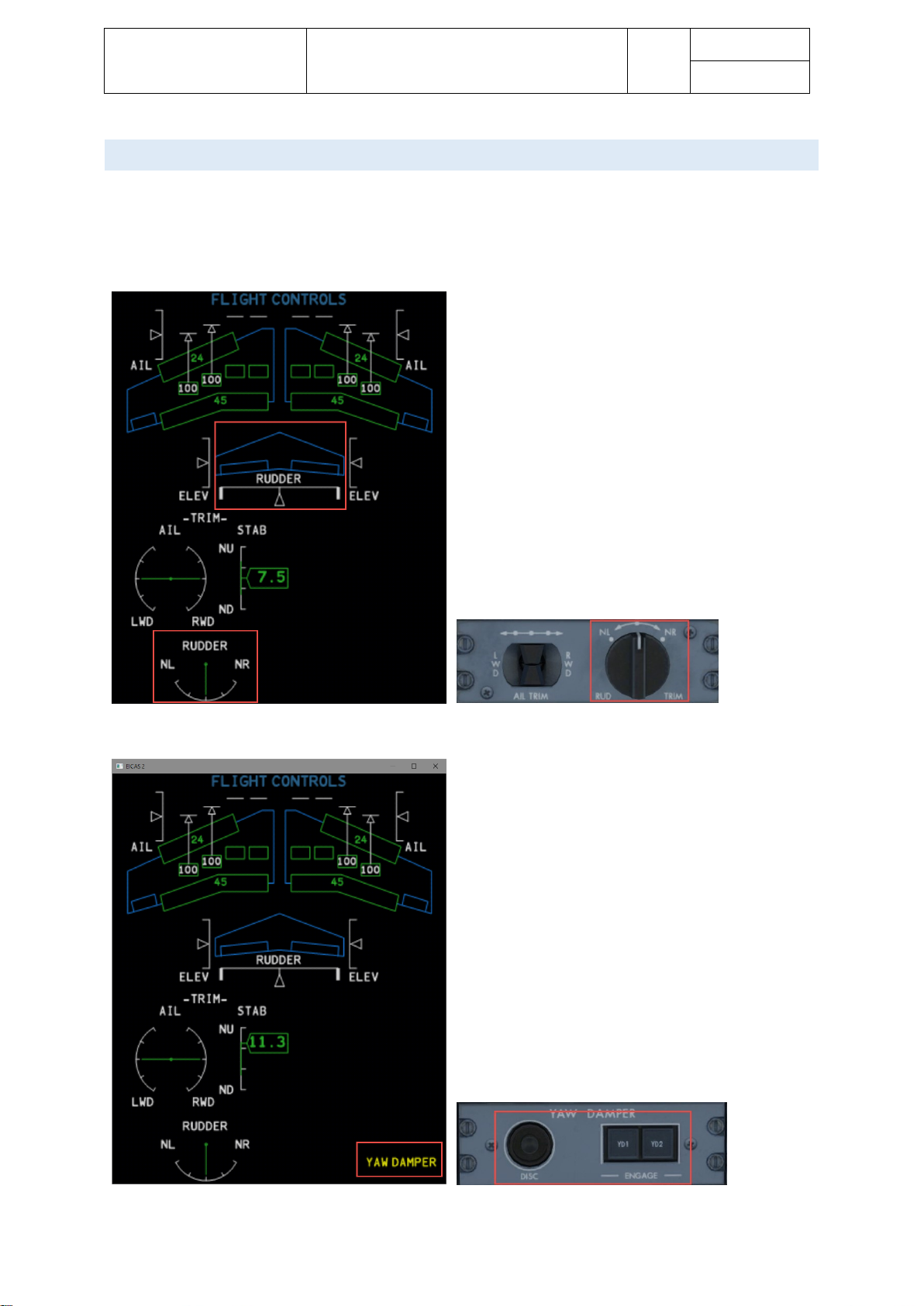
Aerosoft – Digital Aviation
CRJ-70 & CRJ-900
AOM PART 2
Systems Description
VOL
5
5-1-50
26-Jul-2017
RUDDER
Yaw axis is controlled by the rudder mounted to the empennage. The rudder is controlled via the pedals. Two
yaw dampers add to the aircrafts directional stability and keep the aircraft coordinated during turns. The input
signal from the rudder pedals is transferred to the actuators, which deflect the rudder. To minimize side slip
during high speeds, the rudder deflection angle is automatically adjusted over speed (from 33° to 4°).
A yaw damper system can reduce reduce the rolling and yawing oscillations known as the Dutch roll.
Page 51

Aerosoft – Digital Aviation
CRJ-70 & CRJ-900
AOM PART 2
Systems Description
VOL
5
5-1-51
26-Jul-2017
ELE VATOR
The CRJ’s elevators are mounted to the empennage and controlled by either pilot’s yoke. The elevators have
18.4° up movement and 23.6° down movement.
Page 52

Aerosoft – Digital Aviation
CRJ-70 & CRJ-900
AOM PART 2
Systems Description
VOL
5
5-1-52
26-Jul-2017
HORI Z ONTAL ST A BILIZER T RIM
The horizontal trim works a little bit different than the other systems;
when adjusting the trim, the entire stabilizer is moved by two motors and
a jack screw. Pitch trim is limited to +2° up and -13° down.
There are four elevator trim modes:
- Manual trim: The stabilizer is moved according the input from
the trim switches. The adjustment of the stabilizer is adjusted
over speed.
- Autopilot trim: With the autopilot activated it trims
automatically as soon as it detects that loads are building up on
the control surfaces
- AUTO trim: With flaps moving between 0 and 20° AUTO trim
helps to reduce pitch input resulting from moving flaps.
- Mach trim: Helps to compensate the aircrafts tendency of
putting the nose down with increasing Mach numbers
1. Stabilator trim channel engage
2. Mach trim engages
Amber light indicates Mach trim is unserviceable
3. Trim switches (of course the default trim key commands from FS
can also be used.
The trim position is shown on the Flight Control display and
is colour coded:
• Green: Take-off configuration
• White: NOT in Take-off configuration
Page 53

Aerosoft – Digital Aviation
CRJ-70 & CRJ-900
AOM PART 2
Systems Description
VOL
5
5-1-53
26-Jul-2017
FLAPS AND SLAT S
The slats and flaps enable the aircraft to fly at lower speeds without stalling. On the other hand flaps and slats
increase drag and hence fuel flow. Thus, the flaps and slats are moveable to extend and retract them as
needed. The CRJ offers the following positions:
Position
Slats
Flaps
0
Fully retracted
Fully retracted
1
20°
Fully retracted
8
20°
8°
20
8°
20°
30
25° (fully extended)
20°
45
25° (fully extended)
45° (fully extended)
The Slat/flap Position Indicator is shown in degrees
on the engine display and is colour coded:
• Green: Normal operation
• White: Flaps disagree
• Amber dashes: Invalid data
The Slat/flaps Position Bar displays slat/flaps
deployment with the white markers as detents:
• Green: Normal operation
• White: Flaps disagree
• Amber dashes: Invalid or missing data
The Slat/flap Position Indicator is also shown in
degrees on the Flight Control display.
• Green: Normal operation
• White: Flaps/slats disagree
• Amber dashes: Invalid or missing data
Flaps lever controls the extension of slats and flaps, of course the standard FSX
controls can also be used. Please note the Emergency Flaps extension is not
simulated.
Page 54
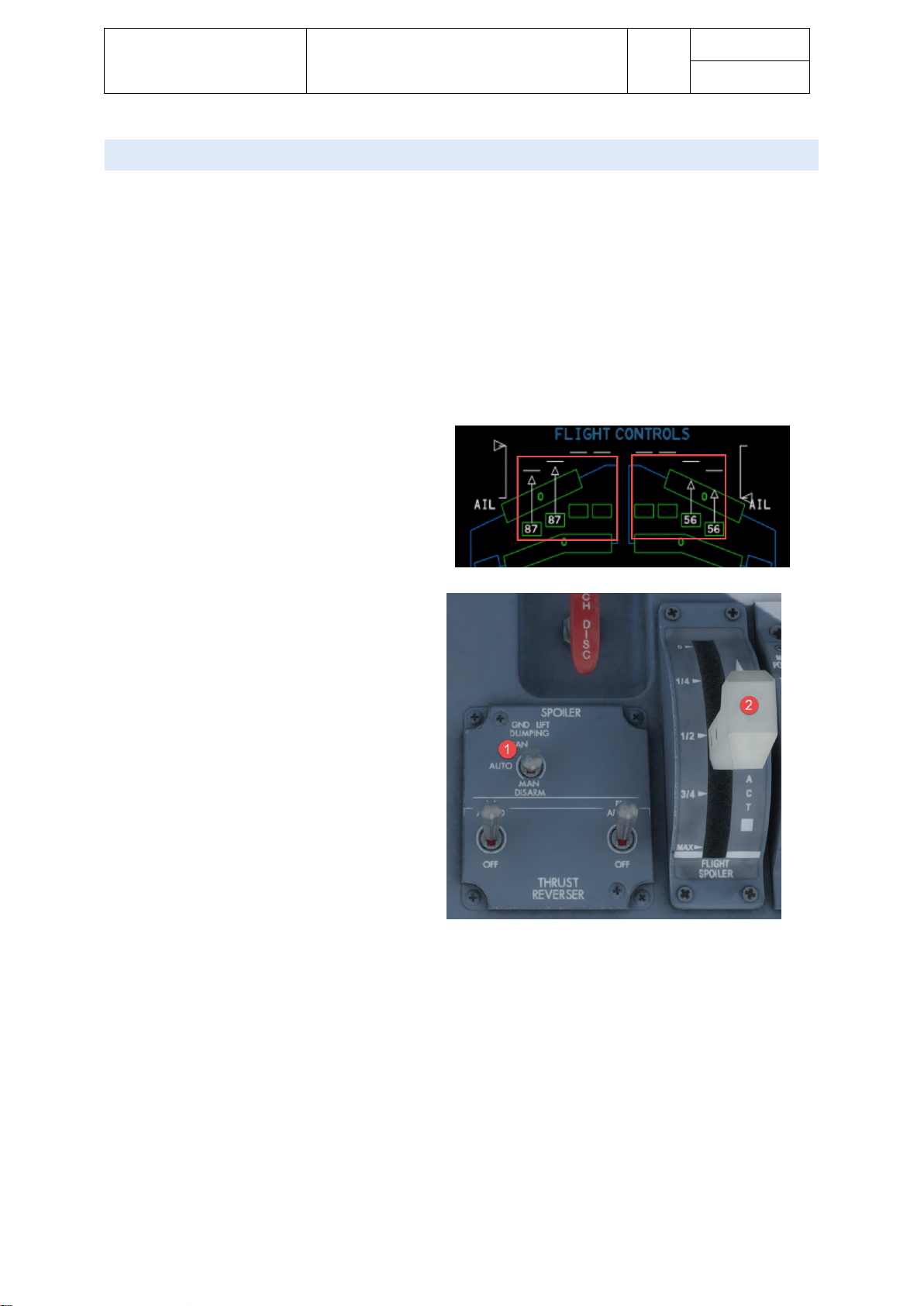
Aerosoft – Digital Aviation
CRJ-70 & CRJ-900
AOM PART 2
Systems Description
VOL
5
5-1-54
26-Jul-2017
SPOIL ERS
To speedup descends, assist in turns and prevent bouncing during landing / touchdown the CRJ is equipped
with spoilers. As already indicated they may be used for different purposes. Accordingly, the spoilers itself are
divided into multifunctional (2 per wing) and ground spoilers (2 per wing)
To extend the spoilers to speed up a descent or to bleed off speed simply pull the spoiler lever back as
required. The multifunctional spoilers will deploy according the setting of the spoiler lever.
Assistance during steep turns is performed automatically by the multifunction spoilers as well.
If the GND LIFT DUMPING switch is not moved to the MAN DISARM position all spoilers will extend as soon as
the aircraft sensed a touchdown or an aborted take-off.
Spoiler positions is shown on the Flight Control
display. The outer two indicated multi-functions
spoilers, the inner two ground spoilers (only deply
on ground).
1. GND LIFT DUMPING: Three-position
switch to select ground lift dumping
mode that prevents the aircraft from
bouncing back into the air on landing:
a. AUTO: Spoiler armed to deploy
on touchdown.
b. MAN ARM: Manually arm
spoilers for deployement
(backup mode for AUTO)
c. MAN DISARM: Disable
automatic deployment.
2. Flight Spoiler Control Lever
Page 55

Aerosoft – Digital Aviation
CRJ-70 & CRJ-900
AOM PART 2
Systems Description
VOL
5
5-1-55
26-Jul-2017
STAL L PROTECTION SYSTEM
As previously mentioned a stall needs to be prevented any time. Accordingly, all aircraft are equipped with at
least a stall warning. The CRJ is equipped with a stall warning and a stick pusher – both together are called the
stall protection system. The angle of attack (AoA) is monitored throughout all flight phases and as soon as the
AoA reaches a critical value the stall computer warns the crew by:
- Activating the stick shaker
- Activates the engines auto-ignition system (to prevent flameout)
- Disengages the autopilot
In case the angle of attack continues to approach the stall point, the stick pusher is activated. The stick pusher
moves the steering column forward to command a nose down attitude to gain speed and prevent the stall.
The STALL PTCT PUSHER switch engages and disengages the stick pusher system.
The STALL pushbutton (guarded) flashes red when the aircraft is approaching
stall conditions. When pushed on the ground it will initiate the stall test
sequence:
• Auti-ignition activated
• Pilot Stick shakers activated for 3 seconds
• Co-Pilot Stick shakers activated for 3 seconds
• After 7 seconds stick pusher is activated
• Stall light flashes
• Press AP/DISC to verify the stick pusher disengages and stall warning are
off.
Page 56

Aerosoft – Digital Aviation
CRJ-70 & CRJ-900
AOM PART 2
Systems Description
VOL
5
5-1-56
26-Jul-2017
FLIG HT INSTRUMENTS
The flight instruments comprise the electronic flight instrument systems, standby instruments and clocks.
The instruments receive data from the aircraft’s sensors via the air data system, radio altimeter and inertial
reference system. All this information is processed to provide the pilots with the following parameters:
• Barometric and radio Altitude
• Vertical speed
• True and indicated airspeed as well as Mach number
• Airspeed trend
• Overspeed warning
• Airplane attitude
• Heading information
• Navigation information
• Temperature
The electronic flight instruments consist of:
• Two primary flight displays, PFDs (one for each pilot)
• Two multi-function flight displays, MFDs (one for each pilot)
The integrated standby instrument (ISI) provides a backup with the following information:
• Aircraft attitude
• Altitude
• Airspeed information
An independent standby compass (Whiskey compass) provides heading information in relation to magnetic
north. The sources of information are:
• Air data system
o Speed
o Altitude
o Temperature data
• Radio altimeter
o Accurate measurement of height above terrain at low altitudes
• Inertial reference system
o Aircraft attitude
o Heading
o Aircraft position
o Angular rate
o Linear acceleration
• Electronic clock
o Time
Page 57

Aerosoft – Digital Aviation
CRJ-70 & CRJ-900
AOM PART 2
Systems Description
VOL
5
5-1-57
26-Jul-2017
ELE C TRONIC FLIGHT INSTRUMENT SYS TEM (EF I S )
Each pilot has a primary flight display, PFD and a multi-functional display, MFD. All 4 units are technically
identical and interchangeable. The PFD’s primary function is to show aircraft attitude, airspeed, altitude, flight
director commands and flight mode annunciations. The MFD’s primary function on the other hand is to
provide navigational information, like heading, bearings.
Page 58

Aerosoft – Digital Aviation
CRJ-70 & CRJ-900
AOM PART 2
Systems Description
VOL
5
5-1-58
26-Jul-2017
DISP L A Y REVERSION
Display reversion is needed in case one PFD fails. It allows to display the PFDs information or EICAS pages on
the MFD. The MFD information cannot be displayed on the PFD though.
DISP L A Y CONTRO L
On either pilot’s side display control panel is installed. It allows selecting of the following:
• MFD format selection
• Bearing point selection
• Navigation source selection
• Cross side navigation data and course display (depends on selected format)
The following formats are available by turning the FORMAT knob:
• HSI compass
• Navaid selector map
• TCAS
• FMS present position map
• FMS plan map
• Weather radar
In case one display control panels fails (this situation is not simulated) the DISPL CONT selector allows the
remaining display control panel to manage all four PFDs and MFDs.
Page 59

Aerosoft – Digital Aviation
CRJ-70 & CRJ-900
AOM PART 2
Systems Description
VOL
5
5-1-59
26-Jul-2017
AIR DATA SYSTEM
The air data system collects information from several sensors of the aircraft (like pitot probes, static ports) to
forward this information directly as well as computing new information from the gathered information to
supply further aircraft systems with.
We’d like to pro provide just some basic information on the air data system as the atmosphere and hence all
parameters which are measurable in real-world are simulated in FS and furthermore faults or failures are not
simulated within this system.
PITOT STATIC S YSTEM
The pitot static system collects dynamic pressure, static pressure and ambient temperature from the pitot
tube, static port and total air temperature probe (TAT probe). It supplies the air data system, integrated standby
instruments and cabin pressure control panel.
Please note that the TAT probes readings are inaccurate when the aircraft is on ground. The TAT probe is heated
to protect it from icing and this leads to inaccurate readings when on ground. During flight the influence of the
heating is neglectable.
AIR DATA
The air data system supplies the following information:
• Corrected pressure altitude (static pressure errors are corrected)
• Vertical speed
• Calibrated and indicated airspeed (CAS / IAS)
• Mach number
• True airspeed
• Static air temperature (SAT)
• Total air temperature (TAT)
• Temperature variations from standard atmosphere (ISA deviation)
Furthermore, the air data system computes and controls the following values and parameters:
• Preselected altitude
• Airspeed trend vector
• Maximum allowable speed (VMO)
• Maximum allowable Mach number (MMO)
• Baro corrected value
• Vertical speed references
Page 60
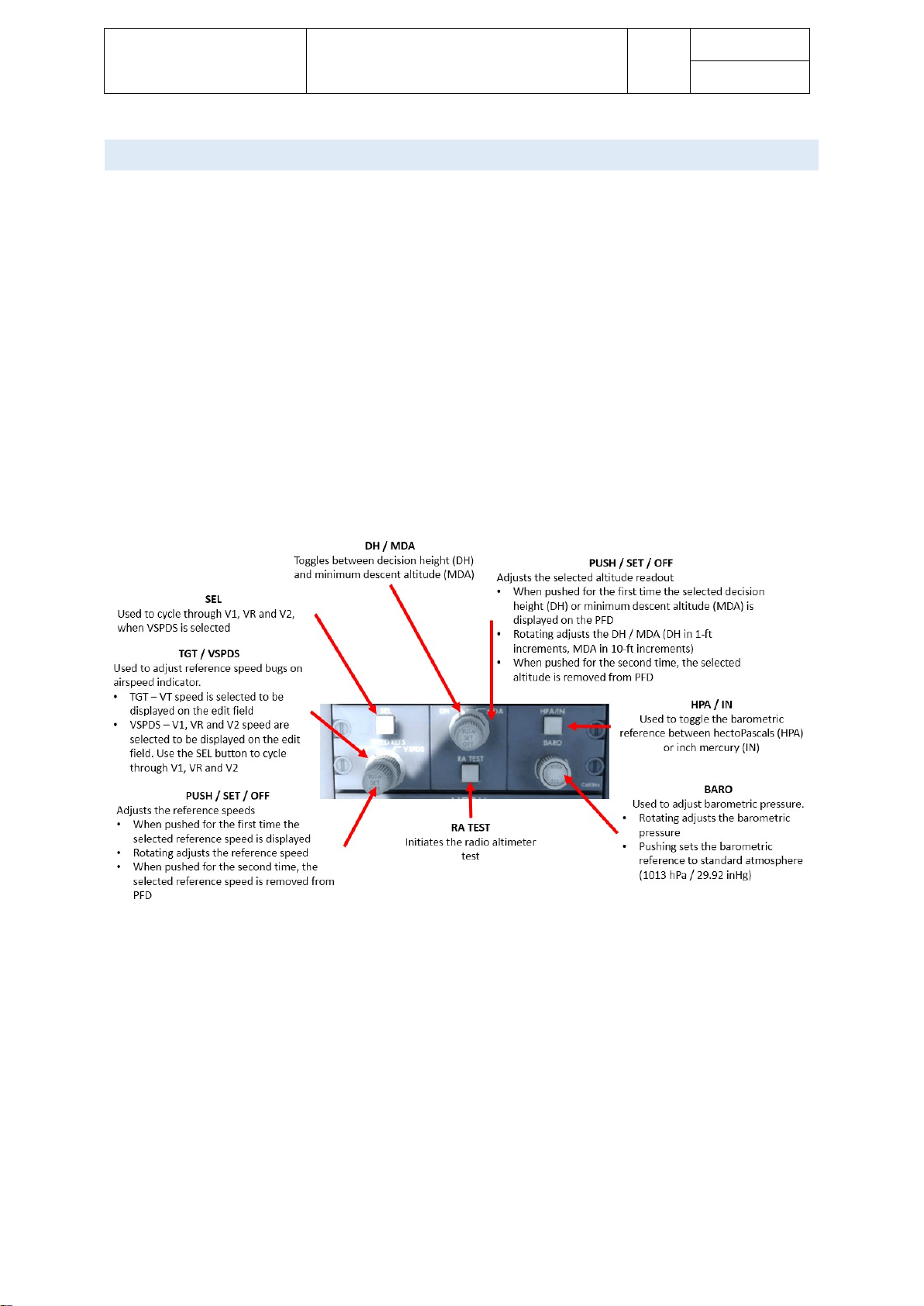
Aerosoft – Digital Aviation
CRJ-70 & CRJ-900
AOM PART 2
Systems Description
VOL
5
5-1-60
26-Jul-2017
AIR DATA REFER ENCE (ARP) PANELS
The air data reference panels – located on either pilot’s side – enable the pilots to enter airspeed reference
pointers and barometric correction for altitude.
The air data reference panels maybe divided into three sections:
- The speed reference section
This section enables the pilot to enter several reference speeds (V1, V2, VR and VT). Both PFDs show the
same values.
- The altitude reference section
Enables the pilot to select minimum descent altitude, MDA, and decision height, DH, value.
Furthermore the radio altimeter self-test is initiated from this section of the ARP panel.
- The barometric reference section
Each PFD may have different barometric pressure settings. The last selected value is saved and
restored after the next power-on. This section allows to:
o Select the barometric pressure for barometric altitude correction
o Switch between hPa or inHg
o Set standard barometric pressure when climbing through transition altitude
Page 61
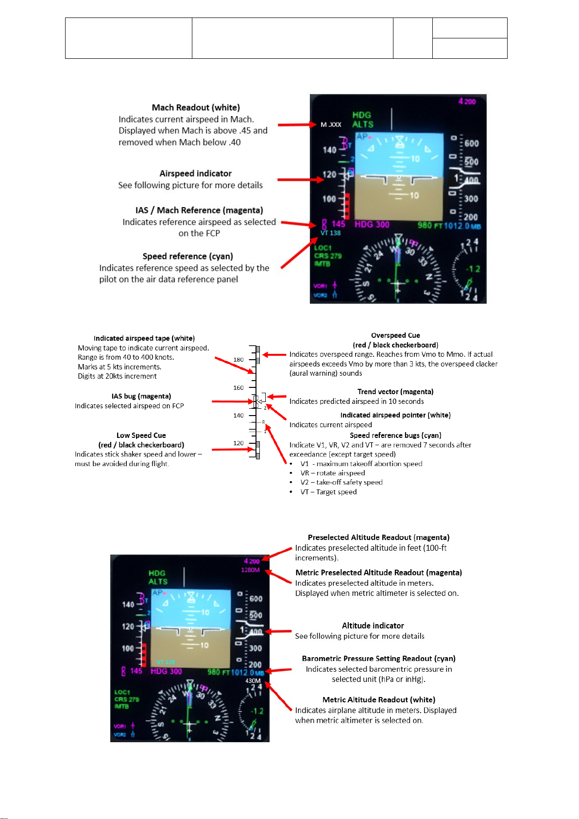
Aerosoft – Digital Aviation
CRJ-70 & CRJ-900
AOM PART 2
Systems Description
VOL
5
5-1-61
26-Jul-2017
Page 62

Aerosoft – Digital Aviation
CRJ-70 & CRJ-900
AOM PART 2
Systems Description
VOL
5
5-1-62
26-Jul-2017
Page 63

Aerosoft – Digital Aviation
CRJ-70 & CRJ-900
AOM PART 2
Systems Description
VOL
5
5-1-63
26-Jul-2017
ALTI TUDE ALERTS
The altitude alerts notifies the crew that preselected altitudes are going to be captured or a deviation from a
preselected altitude occurs.
Three types of altitude alerts may occur:
• Acquisition mode
• Cross side tracking
• Deviation mode
Mode
Short Description
Aural warning
Visual warning
How to cancel
Acquisition mode
Present altitude is
within ±1,000ft or
preselected altitude.
C-chord
Preselected altitude
flashes.
Flashing stops when ±200ft
within preselected altitude
Press altitude
knob on flight
control panel
Cross side tracking
In case a difference
between the
preselected altitudes
from ADC 1 and 2 is
detected
None
Altitude digits change from
magenta to cyan
NIL
Deviation mode
Altitude deviates
more than ±200ft
from preselected
altitude.
OR
Altitude capture is
active and aircraft
deviates from
preselected altitude
by more than ±100ft
C-Chord
Preselected altitude and
bug change from magenta
to amber and start
flashing.
LOW SPEED CUE
The low speed cure displays the speed margin to stick shaker during normal low speed manoeuvers and
approaches to stall. The top of the low speed cue corresponds to stick shaker speed.
AIR DATA REVERSION
During normal operation, each air data computer supplies one pilot’s side with data. In case one air data
computer fails or provides unreliable data, the pilots may switch to the remaining air data computer, which
supplies both pilots’ instruments then.
As failure of an air data computer is not simulated, this function has no relevance in FS even though switching
the selector and the respective message is implemented.
Page 64
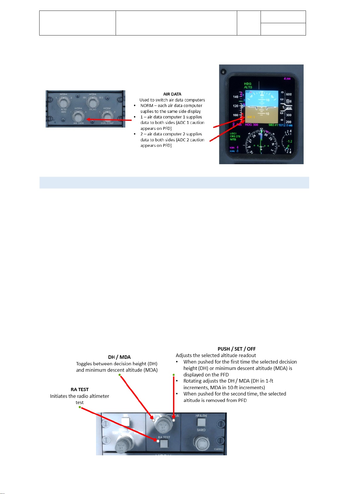
Aerosoft – Digital Aviation
CRJ-70 & CRJ-900
AOM PART 2
Systems Description
VOL
5
5-1-64
26-Jul-2017
RADI O ALTIMETE R SYSTEM
Two radio altimeter systems provide an accurate measurement of the aircrafts altitude over ground within -20
to 2,500ft AGL. The following systems receive data from the radio altimeter:
• PFDs
• Spoiler and stabilizer control units (SSCU)
• Enhanced ground proximity system (EGPWS)
• Traffic alert and collision avoidance system (TCAS)
The PFDs specifically receive the following information from the radio altimeter system:
• Radio altitude readout
Shown as a digital readout as soon as the aircraft descends through 2,500ft.
A moving tape / analogue scale is added as soon as the aircraft descends through 1,225ft.
• Decision height readout
Decision height is selected on the air data reference panel
• Decision height alerts and radio altimeter fail flags
• In case a failure of the radio altimeter is detected, a fail flag is indicated.
A test button on the air data reference panel allows initiating a self-test of the radio altimeter system.
Page 65

Aerosoft – Digital Aviation
CRJ-70 & CRJ-900
AOM PART 2
Systems Description
VOL
5
5-1-65
26-Jul-2017
INER TI AL REFER ENCE SYSTEM
Back in the 1960’s the first inertial reference systems replaced the navigator for trans-oceanic flights. The first
IRS systems used gyros oriented in all three axes. The gyros enable to detect and compute motion the IRS
experiences. Now add a reference / starting point and this enables you to compute the track of an aircraft.
Until today IRS systems were developed further and in conjunction with a GPS system this enables very
accurate computing of the aircrafts position and the flown track as well as attitude changes.
The inertial reference system provides several information to other aircraft systems:
- Attitude
- Heading
- Angular rate
- Linear acceleration
- Present position
The following systems are supplied with those information:
- Flight Control Computers
- Flight Management Computers
- TCAS
- EGPWS
- Fuel system
- Stall protection system
- Flight data recorder
- EFIS
o Attitude Director Indicator, ADI
o Horizontal Situation Indicator, HIS
The IRS normally operates in navigation, NAV, mode. The other available mode, attitude, ATT, mode is used,
when a failure of the unit is detected. As failures of the IRS are not simulated, this mode is not simulated.
Page 66
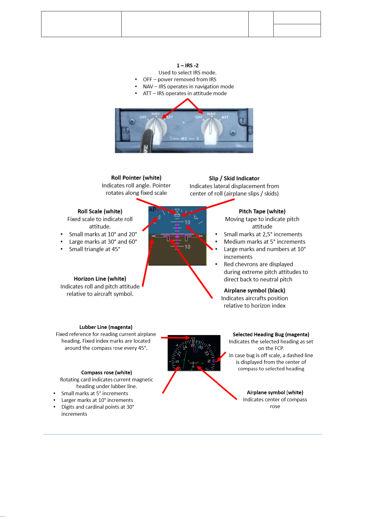
Aerosoft – Digital Aviation
CRJ-70 & CRJ-900
AOM PART 2
Systems Description
VOL
5
5-1-66
26-Jul-2017
DISP L A Y REVERSION
Normally each Inertial Reference System supplies data to the respective PFD / MFD. The ATT HDG knob on the
source selector panel allows to switch between normal configurations (each IRS supplies the same side
displays) or select the specific IRS 1 or 2. The selection is indicated by a yellow single source flag on the PFD.
Page 67
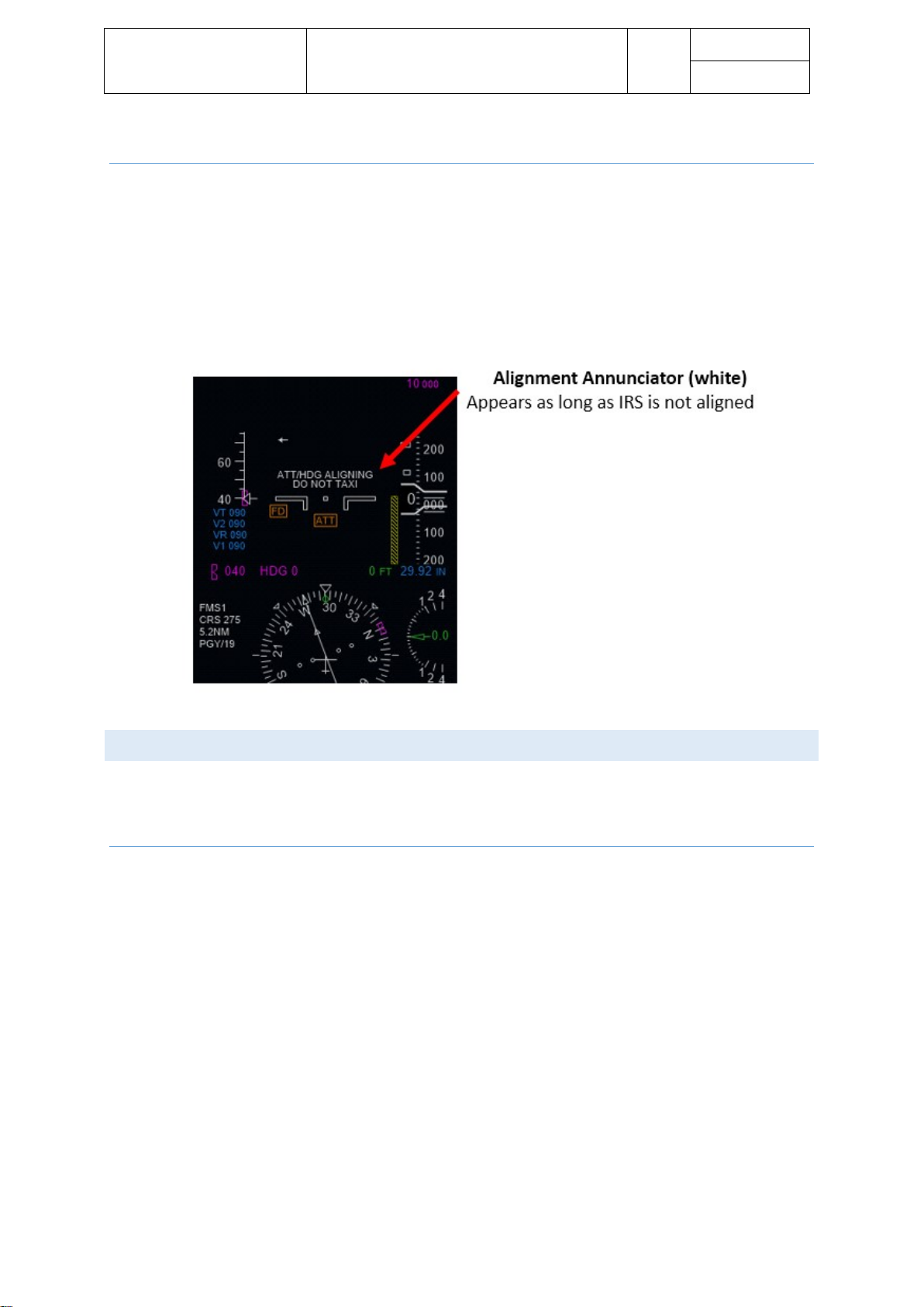
Aerosoft – Digital Aviation
CRJ-70 & CRJ-900
AOM PART 2
Systems Description
VOL
5
5-1-67
26-Jul-2017
INITIALIZATION AND ALIGNMENT
Initialization of the IRS systems takes approximately 7 minutes. To complete the process the present position
needs to be entered in the POS INIT page of the flight management system. During initialization, an
initialization alignment message is flashing on the PFD.
Dave allows you to modify initialization time. You may choose between
• Realistic – initialization takes 6 to 17 minutes
• Fast - initialization takes 3 minutes
• Instant – as soon as the switches are set to NAV and position initialization on the FMS is done, the IRS
is aligned
STAN D BY INSTR U M ENTS A N D CLOCKS
The integrated standby instrument is located between the EICAS displays on the center instrument panel. The
standby compass sits under the overhead panel on the center window post. Each pilot has a clock on his side
panel.
INTE G R ATED STA NDBY INSTRUMENT
The integrated standby instrument, ISI, is supplied with electrical power from the battery bus to ensure
operation even under emergency conditions. They provide attitude, altitude and airspeed information. Air data
input is coming from the alternate pitot probe and static ports.
The ISI is capable to display the following information:
• Attitude
• ILS deviation
• Corrected altitude
• VMO display
• Airspeed
• Static source error correction (SSEC)
• Mach number
• Barometric pressure
• Slip-skid indication
Page 68

Aerosoft – Digital Aviation
CRJ-70 & CRJ-900
AOM PART 2
Systems Description
VOL
5
5-1-68
26-Jul-2017
STAN D BY COMPA S S
The standby compass is a self-contained dry compass with damping to reduce overshooting. It is independent
from all other aircraft systems. A miniature aircraft symbol indicates the aircrafts heading in relation to
magnetic north.
Page 69
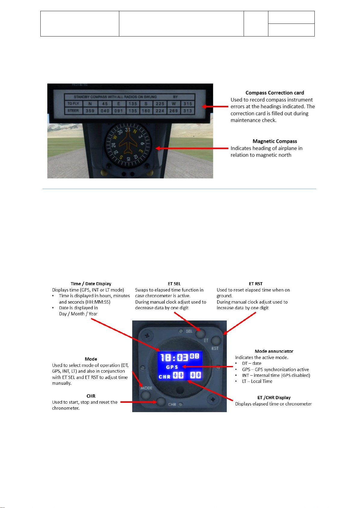
Aerosoft – Digital Aviation
CRJ-70 & CRJ-900
AOM PART 2
Systems Description
VOL
5
5-1-69
26-Jul-2017
The compass correction card, sitting above the compass rose, shows the correction values to subtract or add to
the indicated heading for compensation of metallic or magnetic materials in the aircraft, influencing the
compass rose.
CLOC K S
A digital clock is installed on either pilots’ side panel. The clock is normally synchronized with a time signal from
the GPS, which happens automatically during aircraft start-up. In case the GPS sync is interrupted, the clock
switches to internal (INT) mode.
The clock features the following modes
• Display date (GPS or UTC)
• Display current time (GPS, internal UTC or local)
• Chronometer (CHR) function
• Elapsed Timer (ET)
Page 70
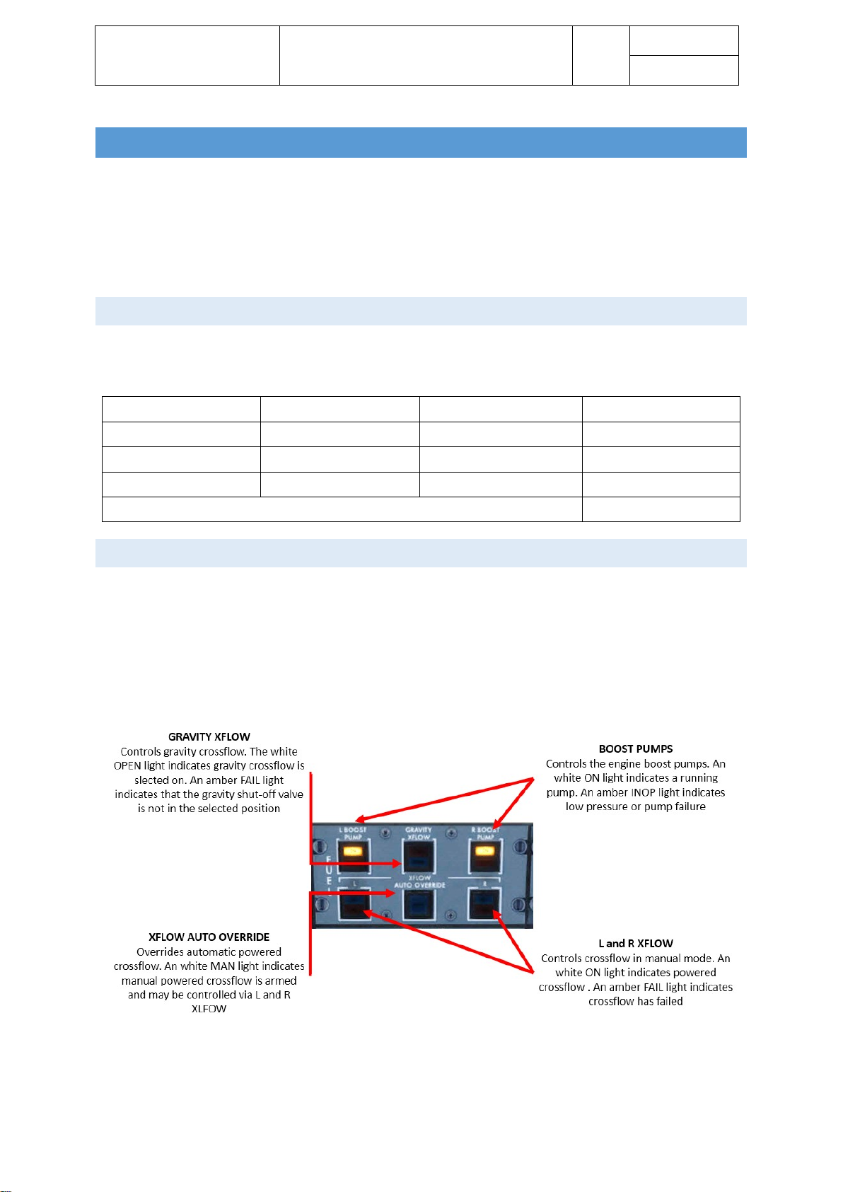
Aerosoft – Digital Aviation
CRJ-70 & CRJ-900
AOM PART 2
Systems Description
VOL
5
5-1-70
26-Jul-2017
FUE L SYSTEM
The fuel system is comprised of the following subsystems:
• Fuel tanks / storage
The CRJ has three tanks: two wing and one center tank
• Fuel management (transfer/crossflow) & distribution
• Fuel quantity gauging
FUEL TANKS / S T ORAGE
Fuel is stored in both wing and the center tank. The wing tanks are emptied first. With decreasing fuel in the
wing tanks, fuel is transferred from the center tank into the wing tanks, in case the center tank is filled.
Tank
Useable fuel
Unusable fuel
Total fuel
Left wing tank
7’493 lbs / 3’399 kg
62 lbs / 28 kg
7’554 lbs / 3’427 kg
Center tank
4’610 lbs / 2’091 kg
32 lbs / 14 kg
4’642 lbs / 2’106 kg
Right wing tank
7’493 lbs / 3’399 kg
62 lbs / 28 kg
7’554 lbs / 3’427 kg
Total
19’750 lbs / 8’960 kg
FUEL MANAGEM E NT (TRANS F ER/CROSSFLOW) & DI STRIBUTI ON
Fuel transfer from the center to the wing tanks is done automatically. The monitoring computer stars transfer
as soon as the wing tank’s quantity drops below 93% and ends transfer either when the center tank is empty or
the wing tank reaches 97%. Fuel crossflow between the wing tanks may be performed powered or by gravity.
Fuel crossflow is used to equalize imbalances between the wing tanks to maintain lateral stability.
A pump in the center tank provides powered crossflow either in automatic or in manual mode. In automatic
mode, a computer monitors imbalanced and starts equalizing on its own. This mode may be overridden by the
crew and crossflow controlled manually.
The following graphic shows how valve positions are displayed on the Fuel EICAS Synoptic page.
Page 71

Aerosoft – Digital Aviation
CRJ-70 & CRJ-900
AOM PART 2
Systems Description
VOL
5
5-1-71
26-Jul-2017
Page 72

Aerosoft – Digital Aviation
CRJ-70 & CRJ-900
AOM PART 2
Systems Description
VOL
5
5-1-72
26-Jul-2017
The engines are supplied with fuel from the so-called side collective tanks. These two tanks are structural part
of the central tank but are separate tanks though. To prevent fuel starvation during manoeuvring, the
collective tanks are continuously filled up by the monitoring computer system. Boost pumps support fuel feed
to the engines in case of a pressure drop in the fuel line. The boost pumps are normally on standby but as soon
as a pressure drop is sensed, the boost pumps are activated. During engine start the boost pumps are
activated as well, independent of the pressure in the fuel line.
The APU is supplied from the left collective tank. The APU fuel pump ensures sufficient pressure on the fuel
line to the APU. Activating the APU also activates the APU fuel pump.
FUEL Q UANTITY GAUGING
Several probes in the wing center and collective tanks determine the amount of fuel in the respective tank,
fuel temperature and fuel density. These signals are processed by a computer system to correct errors due to
wing deflection, or density changes. The resulting fuel quantities, temperature and amount of used fuel are
displayed on the EICAS.
Page 73

Aerosoft – Digital Aviation
CRJ-70 & CRJ-900
AOM PART 2
Systems Description
VOL
5
5-1-73
26-Jul-2017
Page 74

Aerosoft – Digital Aviation
CRJ-70 & CRJ-900
AOM PART 2
Systems Description
VOL
5
5-1-74
26-Jul-2017
HYDRAULIC POWER
The CRJ has three hydraulic systems. Systems 1 and 2 are identical. All three systems operate on a nominal
pressure of 3,000 PSI. Each system has two pumps. A main pump (A) for normal power and a backup pump (B).
System 1 and 2’s main pumps are engine driven pumps (EDP). The backup-pumps are AC-motor pumps
(ACMP). Pump 1A is driven by the left engine, while pump 2A is driven by the right engine.
System 3 has two AC motor pumps. Pump A runs continuously whereas pump B is only running when high
flows of hydraulic are required. In case supply of AC fails, pump 3B may be supplied by the ADG.
Except pump 3A all pumps have three operation-Modes:
• ON
• AUTO
• OFF
In AUTO mode, the pumps will start running automatically under the following conditions:
• AC BUS 2 must be powered for pump 2B operation
• AC BUS 1 must be powered for pump 1B operation
• Flaps are out if the 0° position
In case of an engine fire the engine-driven pump of the affected engine needs to be shut off with the engine
being shut off. Hence a shut-off valve is installed for pumps 1A and 2A to shut them off as well as son as the
fire handle for the engine is pulled. Closing this shut-off valve can also be done manually.
Page 75

Aerosoft – Digital Aviation
CRJ-70 & CRJ-900
AOM PART 2
Systems Description
VOL
5
5-1-75
26-Jul-2017
The following table shows which aircraft system is supplied by which hydraulic system.
System 1
System 3
System 2
Engine driven
pump (1A)
AC motor
pump (1B)
AC motor
pump (3A)
AC motor
pump (3B)
Engine driven
pump (2A)
AC motor
pump (2B)
Rudder
Rudder
Rudder
Left and right elevator
Left and right elevators
Left and right elevator
Left aileron
Left and right aileron
Right aileron
Left and right outboard spoilerons
Main and nose landing gear
Left and right MLG and NLG assist
actuators
Left and right outboard spoilers
Left and right inboard brakes
Left and right outboard brakes
Left and right outboard ground
spoilers
Left and right inboard ground
spoilers
Left and right inboard spoilerons
Left thrust reversers
Nosewheel steering
Left and right inboard spoilers
Right thrust reversers
Further information on valve positions, pressures and hydraulic fluid quantities may be obtained on the
Hydraulic (HYD) EICAS Synoptic page.
Hydraulic systems 1 & 2:
Page 76
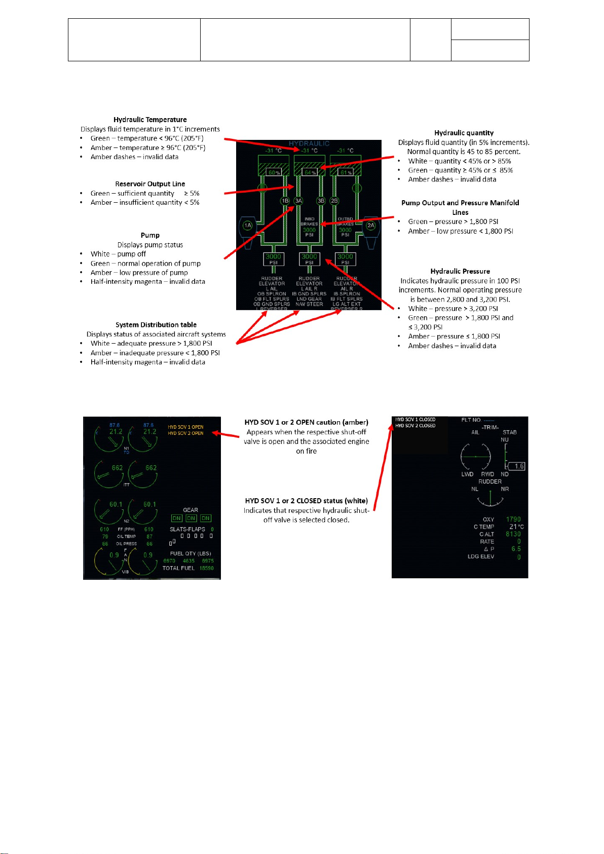
Aerosoft – Digital Aviation
CRJ-70 & CRJ-900
AOM PART 2
Systems Description
VOL
5
5-1-76
26-Jul-2017
Hydraulic systems 3:
Just a few cautions and status messages may be triggered by the hydraulic system.
Page 77

Aerosoft – Digital Aviation
CRJ-70 & CRJ-900
AOM PART 2
Systems Description
VOL
5
5-1-77
26-Jul-2017
ICE & RAIN PR OTECTION
The aircraft does not need much protecting from rain if no icing conditions persist (definition is coming up in a
second), hence windshield wipers are the only system for rain protection.
Icing conditions are defined as follows:
TAT of 10°C and less and visible moisture like fog, clouds, any form of precipitation,
except the SAT is -40°C (-40°F) or below.
Icing may affect the functionality of certain aircraft systems, alter the aerodynamic of the aircraft’s wings and if
sucked into the engine lead to engine trouble. Hence several systems need to be protected from icing:
• The wings leading edges
• Air data sensors like pitot tubes, angle of attack sensors, static ports, etc. pp)
• The engine intakes / cowls
• The cockpit windows
There are two approaches to heat the mentioned systems / areas: either by extracting bleed air from the
aircraft engines or by means of an electrical heating.
Apparently extracting bleed air from the engines reduces the available amount of thrust. Accordingly, the
engines RPM must be increased a little to compensate the extracted air for heating. Therefore, you’ll
experience an increase of N1, when activating the anti-ice systems. The more systems are supplied with bleed
air the bigger the increase of N1 is going to get.
The following systems are heated with bleed air:
• Wing anti-ice
• Engine intake cowl anti-ice
Whereas the following systems are electrically:
• Windshields and side windows
• Air data probes and sensors
An ice detection system assists the crew by warning of possible ice accumulation. The ice detection system is
operational as soon as AC power is available. In case either detector senses icing conditions an amber caution
“ICE” is indicated on the EICAS if either the wing- or cowl-anti-ice system is still off. Failures of the anti-ice
systems as well as bleed air leakages are not simulated.
The following sections introduce the controls for each sub-system, the indications on the Anti-Ice EICAS
Synoptic Page as well as possible EICAS messages.
Page 78

Aerosoft – Digital Aviation
CRJ-70 & CRJ-900
AOM PART 2
Systems Description
VOL
5
5-1-78
26-Jul-2017
ICE DETECTION SYSTEM
Page 79

Aerosoft – Digital Aviation
CRJ-70 & CRJ-900
AOM PART 2
Systems Description
VOL
5
5-1-79
26-Jul-2017
WING A ND COWL ANTI-ICE S YSTEM
Page 80

Aerosoft – Digital Aviation
CRJ-70 & CRJ-900
AOM PART 2
Systems Description
VOL
5
5-1-80
26-Jul-2017
AIR DATA ANTI -IC E SYSTEM
Page 81

Aerosoft – Digital Aviation
CRJ-70 & CRJ-900
AOM PART 2
Systems Description
VOL
5
5-1-81
26-Jul-2017
WIND S HIELD AND SIDE WI NDOW ANTI -ICE SYSTEM
WIND S HIELD WI P ER SYSTEM
Page 82

Aerosoft – Digital Aviation
CRJ-70 & CRJ-900
AOM PART 2
Systems Description
VOL
5
5-1-82
26-Jul-2017
LANDING GEAR
The CRJ is equipped with two main landing gear assemblies mounted in either wing-root, and a forward,
steerable, fuselage mounted nose gear assembly. Each assembly is equipped with two wheels and a braking
system.
Gear extraction and retraction is triggered electrically by the landing gear selector whereas the extension and
retracting is actuated hydraulically (by hydraulic system 3).
In case the normal extension mechanism fails an alternate gear extension mechanism is available: just pull the
landing gear manual release handle to unlock the gear uplocks. Due to gravity, the gear will partially extend. A
combination of valves in the hydraulic system is activated to divert pressure from the No. 2 system to complete
the gear extension and lock the gear in the down position.
Page 83

Aerosoft – Digital Aviation
CRJ-70 & CRJ-900
AOM PART 2
Systems Description
VOL
5
5-1-83
26-Jul-2017
BRAK E SYSTEM
Each wheel of the gear assembly is equipped with self-adjusting multi-disc brakes. The inboard brakes are
actuated by hydraulic system no. 3. Brake pressure is applied by pressing the rudder pedals. To enable this
feature within your flightsim make sure that the toe brake axis is assigned to your rudder pedals brake axis or
whichever axis you prefer.
PARKI NG BRAKE
To activate the parking brake fully press the brake/rudder pedals, pull the parking brake lever and twist it 90° in
either direction. The inboard brake control valves and the parking shutoff valve prevent a pressure drop in the
system due to leakages when the parking brake is set.
Page 84

Aerosoft – Digital Aviation
CRJ-70 & CRJ-900
AOM PART 2
Systems Description
VOL
5
5-1-84
26-Jul-2017
BRAK E TEMPERATURE MONI TORING SYS TEM
The main wheel brakes temperature is monitored and indicated on the EICAS as long as the gear and flap/slats
position are indicated on the EICAS. In case an overheat condition is detected and no longer persists, the
warning may be reset by the BTMS overheat warning reset switch.
Each brakes temperature is indicated as a colour-coded numerical value:
Colour-code
Numerical values
Temperature range
Green
01 – 06
≤ 220°C
White
07 – 14
≥ 221°C and ≤ 492°C
Red
≥ 14
≥ 493°C
Page 85

Aerosoft – Digital Aviation
CRJ-70 & CRJ-900
AOM PART 2
Systems Description
VOL
5
5-1-85
26-Jul-2017
ANTI - S KID
The anti-skid-system controls the hydraulic pressure applied to the wheel brakes and performs the following
functions:
- Prevent skidding
- Protection during touchdown – even though the brake pedals may be pressed / applied, a landing with
locked wheels is prevented
- Recovering of a wheel from deep skid
The anti-skid-system comprises four-wheel speed transducers and two dual anti-skid control valves.
It may only be activated when both main gears are locked in the down position and the parking brake is not
activated. The anti-skid switch needs to be switched to the ARM position and the system becomes operation
automatically as soon as passing 35 knots on ground (weight-on-wheels signal is present).
As soon as the aircraft is in the air (and there is no weight-on-wheels signal) brake pressure is dumped to
prevent a landing with locked wheels.
Page 86
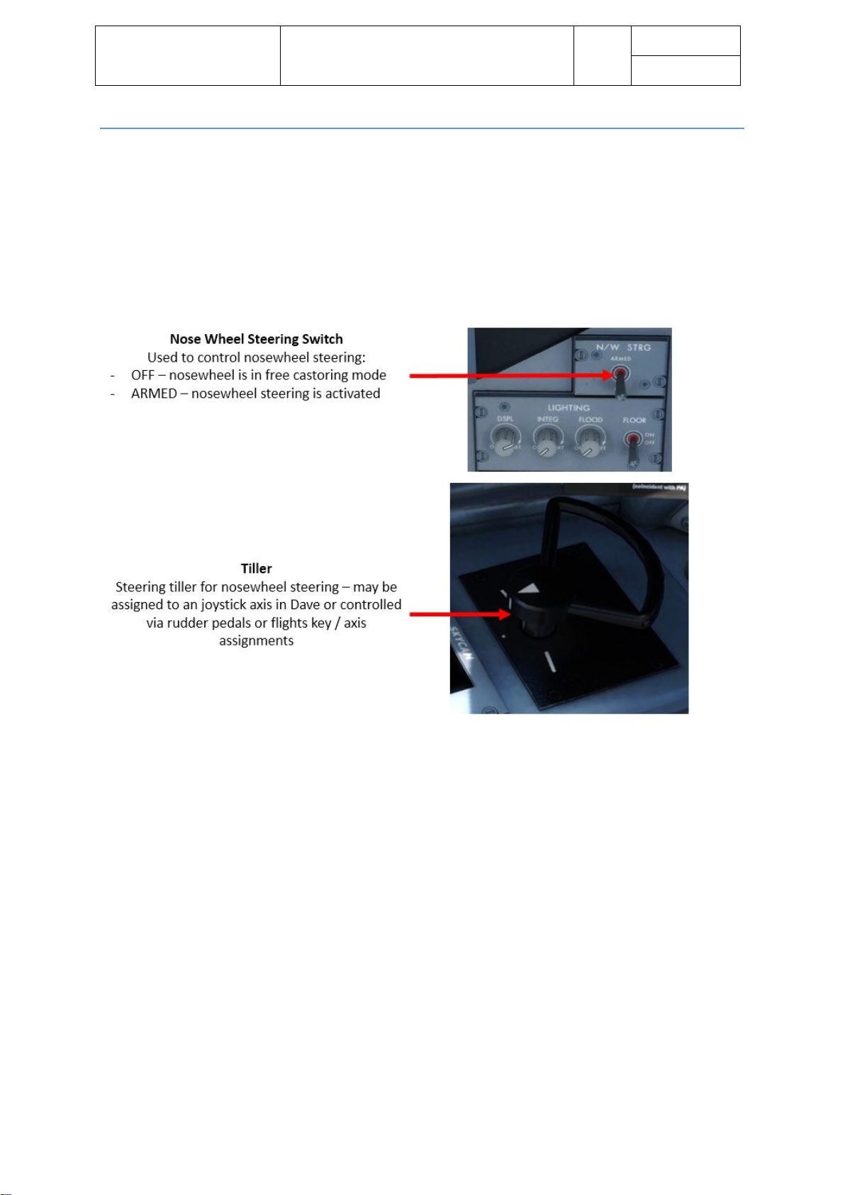
Aerosoft – Digital Aviation
CRJ-70 & CRJ-900
AOM PART 2
Systems Description
VOL
5
5-1-86
26-Jul-2017
NOS E WHEEL S TEERING SYSTEM
Unlike in most other aircraft the CRJ’s nosewheel steering needs to be activated manually by selecting the N/W
STRG switch to the ARMED position. Then you can turn the nosewheel up to 80° either side of center with the
steering tiller mounted on the pilot’s side panel. Deflection controlled by the rudder pedals is limited to 8°
either side of center.
As soon as the aircraft is in the air (no weight-on-wheel signal detected) the systems commands straight ahead.
In case the steering tiller is deflected more than 2° while in air (i.e. before touchdown) the STEERING INOP
caution message will appear on the EICAS
.
Page 87

Aerosoft – Digital Aviation
CRJ-70 & CRJ-900
AOM PART 2
Systems Description
VOL
5
5-1-87
26-Jul-2017
LIGHTING
This chapter is divided into the following sections:
• Cockpit lighting
Controls on overhead panel
• Passenger compartment lighting
Controls on forward attendant’s panel → not simulated
• External lighting
Controls on overhead panel
• Emergency lighting
Controls on overhead panel
COCK PIT LIGHTI NG
Several types of lighting are available in the cockpit:
- General area illumination
o Dome light
Not simulated
o Floor lights
Not simulated
- Instrument and panel lighting
o CRT intensity control
Allows to control intensity of the pilots displays (PFD, MFD, EICAS)
o Integral lighting
Switches cockpit internal lighting on and off
o CB braker panel lighting
Not simulated
- Map and reading lights
Not simulated
Page 88

Aerosoft – Digital Aviation
CRJ-70 & CRJ-900
AOM PART 2
Systems Description
VOL
5
5-1-88
26-Jul-2017
PASSENGER COM PARTMENT LIGHTI NG
The real aircraft offers several types of lighting for the passenger compartment, like ceiling and sidewall
fluorescent lights.
The only lights that may be controlled in FS are the NO SMOKING and FASTEN SEAT BELTS signs.
Page 89
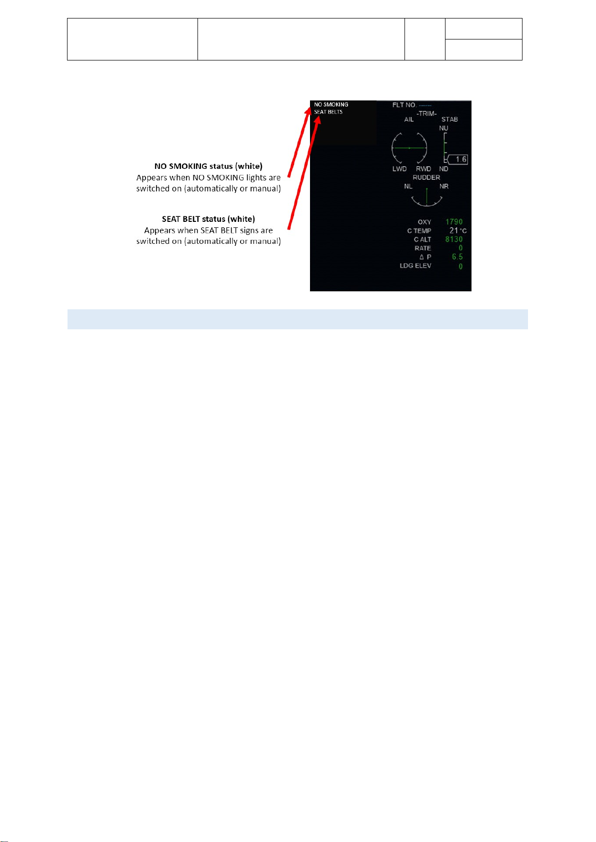
Aerosoft – Digital Aviation
CRJ-70 & CRJ-900
AOM PART 2
Systems Description
VOL
5
5-1-89
26-Jul-2017
EXTERNAL LIGHTI NG
External lighting is simulated identical to the real aircraft. The external lights comprise:
- Landing and taxi lighting
The CRJ has three landing lights – one in each wing’s leading edge and one installed on the nose gear.
The 2 taxi lights are installed next to the landing lights in the wind’s leading edge.
- Navigation lighting
The navigation lights are installed in each wingtip. Each navigation light assembly consists of two lights
– two green lights on the right hand side and two red lights on the left hand side.
The lights are controlled via the NAV light switch on the overhead panel.
- Beacon light
Two beacon lights are installed on the CRJ – one on top of the fuselage and the other one on the
bottom of the fuselage. Activated beacon lights indicate that the aircraft is powered and the engines
may be running.
The BEACON light switch controls the beacon lights.
- Anti-Collision strobe lights
Three anti-collision lights are installed on the aircraft. Two on either wingtip and one on the aft end of
the vertical stabilizer. The anti-collision lights flash continuously as soon as activated and are normally
activated after take-off clearance is received and switched off when leaving the runway.
The STROBE switch is used to switch the anti-collision lights on and off.
- Logo lights
As the name suggests the logo lights illuminate the aircrafts logo depicted on the tail. Two white lights
are installed in the engine pylons – one on either side.
The lights are controlled by the LOGO switch.
- Wing inspection lighting
The wing inspection lights are used to inspect the forward part of the wing for ice accumulation. The
wing inspection lights are installed on either side of the fuselage and controlled by the WING INSP
switch.
Page 90

Aerosoft – Digital Aviation
CRJ-70 & CRJ-900
AOM PART 2
Systems Description
VOL
5
5-1-90
26-Jul-2017
Page 91

Aerosoft – Digital Aviation
CRJ-70 & CRJ-900
AOM PART 2
Systems Description
VOL
5
5-1-91
26-Jul-2017
EMER G ENCY LIGHT I NG
Emergency lighting of the real airplane consists of the overwing exit paths, the exterior area around the
passenger doors / emergency exits, interior exit paths, lighting of the emergency exits and so on.
Even though the controls are available in the virtual cockpit, the emergency lighting is not simulated and hence
not further explained.
NAVIGATION SY STEMS
This chapter describes several navigation systems, each is described in its own section. The chapter is
comprised of the following sections:
• Flight Management System (FMS)
• Global Positioning System (GPS)
• VHF Navigation (VNAV)
• Automatic Direction Finder (ADF)
• Distance Measuring Equipment (DME)
• Air Traffic Control Transponder System (ATC)
• Traffic Alert and Collision Avoidance System (TCAS)
• Ground Proximity Warning System (GPWS)
• Weather Radar (WXR)
Page 92
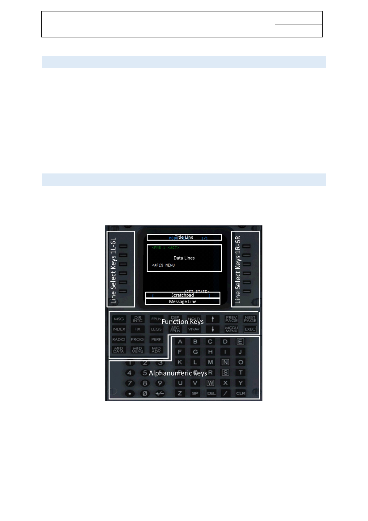
Aerosoft – Digital Aviation
CRJ-70 & CRJ-900
AOM PART 2
Systems Description
VOL
5
5-1-92
26-Jul-2017
FLIG H T MANAG E M ENT SYSTEM (FMS)
The CRJ is powered by two Collins FMS-4200 flight management computers. The control display units (CDU)
are the interface between pilots and the FMS units itself by means of data / information display and data
entry. The FMS provides lateral guidance and vertical advisories based on the entered flight route,
performance data and data collected from several sensors.
The stored performance database is advisory only, as the FMS has no ability to control vertical or speed modes
of the autopilot. Only heading information based on the programmed route are provided to the autopilot in
LNAV mode.
This chapter in the systems manual only provides a very basic introduction to the flight management system.
More details will be introduced in a dedicated manual (Vol. 6).
WHE RE TO FIND THE FMS/ CDU AND B A SIC LAYOUT
The control display units, CDUs sit on the upper part of the pedestal. Both CDUs are identical regarding
functionality and layout.
The following picture shows the basic layout of the control display unit, CDU.
- Title line
The title line shows the page title, or mode as well as the current page number and number of total
pages, of applicable
- Label line
The label lines are aligned with the respective line select keys. They show information related to the
current page. Pressing the line select key adjacent to the label line, allows copying the indicated
information into the scratchpad or vice versa.
Page 93

Aerosoft – Digital Aviation
CRJ-70 & CRJ-900
AOM PART 2
Systems Description
VOL
5
5-1-93
26-Jul-2017
- Prompts / Dashes
Boxes indicate where information need to be entered in the FMS.
Dashes indicate where information may be entered.
- Data lines
Provide further information to the indicated data in the same label line (i.e. distance information on
the LEGS page)
- Scratchpad
Text entered via the keypad or copied from a label line via the line select key is displayed in the
scratchpad
- Message line
The message line indicates system generated
- Left Line Select Keys LSL1L to LSK6L
Allow to enter and copy data from the data lines into the scratchpad and vice versa.
- Right Line Select Keys LSL1R to LSK6R
Allow to enter and copy data from the data lines into the scratchpad and vice versa.
- Function Keys
Pressing a function key calls /opens the associated page
o MSG
Opens the FMS message page
o DIR/INTC
Opens the DIRECT-TO page
o FPLN
Opens the Flightplan page to enter and modify a flightplan
o DEP/ARR
Opens the Departure and Arrival page to select SIDs and STARs
o HOLD
Opens the HOLDING page to program holdings
o ↑ and ↓
For scrolling up and down – for example to modify the center for the flight plan page
o PREV PAGE
Opens previous page
o NEXT PAGE
Opens next page
o INDEX
Opens INDEX page to access FMS functions which have no direct-access-keys
o FIX
Opens the FIX INFO page
o LEGS
Opens the LEGS page to modify a flightplan’s legs
o SEC FPLN
Opens secondary fligthplan page
o VNAV
Opens VNAV page for VNAV advisories
o MCDU MENU
Opens the ENU page
o EXEC
The EXEC button executes modifications made
o RADIO
Opens the radio programming page (NAV, COM, ADF)
Page 94

Aerosoft – Digital Aviation
CRJ-70 & CRJ-900
AOM PART 2
Systems Description
VOL
5
5-1-94
26-Jul-2017
o PROG
Opens the Progress page to show a summary of the current flight status
o PERF
Opens the Performance page
o MFD DATA
Allows to switch between map and text display
o MFD MENU
Allows to look deeper into the FMS data source regarding airports, navaids, fixes and modify
data
o MFD ADV
Opens the DISPLAY ADVANCE page to move through the MFD text pages.
- Keypad
Used to enter alpha-numerical data in to the scratchpad.
You may use your mouse to enter data into the FMS and select certain functions, nevertheless you may also
activate a mode to use keyboard commands to directly enter data / select functions from the FMS. Please bear
in mind that as long as the keyboard mode is activated other key assignments in your flightsim won’t work.
Note
In case you are using the keyboard entry mode do not forget to deactivate it when entries are completed to
gain full function of regular flightsim functions.
The table on the following page shows the available key commands.
Page 95

Aerosoft – Digital Aviation
CRJ-70 & CRJ-900
AOM PART 2
Systems Description
VOL
5
5-1-95
26-Jul-2017
Function
German Keyboard
U.S. Keyboard
Toggles left MCDU keyboard entry mode ON/OFF
Strg+Umschalt+1
Ctrl+Shift+1
Toggles right MCDU keyboard entry mode ON/OFF
Strg+Umschalt+2
Ctrl+Shift+2
LSK 1L
F1
F1
LSK 2L
F2
F2
LSK 3L
F3
F3
LSK 4L
F4
F4
LSK 5L
F5
F5
LSK 6L
F6
F6
LSK 1R
F7
F7
LSK 2R
F8
F8
LSK 3R
F9
F9
LSK 4R
F10
F10
LSK 5R
F11
F11
LSK 6R
F12
F12
MSG
Strg+F1
Ctrl+F1
Dir/Intc
Strg+F2
Ctrl+F2
Fpln
Strg+F3
Ctrl+F3
Dep/Arr
Strg+F4
Ctrl+F4
Hold
Strg+F5
Ctrl+F5
MCDU Menu
Strg+F6
Ctrl+F6
Index
Strg+F7
Ctrl+F7
Fix
Strg+F8
Ctrl+F8
Legs
Strg+F9
Ctrl+F9
Sec Fpln
Strg+F10
Ctrl+F10
VNAV
Strg+F11
Ctrl+F11
Exec
Return oder Strg+F12
Return or Ctrl+F12
Radio
Umschalt+F1
Shift+F1
Prog
Umschalt+F2
Shift+F2
Perf
Umschalt+F3
Shift+F3
MFD Data
Umschalt+F4
Shift+F4
MFD Menu
Umschalt+F5
Shift+F5
MFD Adv
Umschalt+F6
Shift+F6
A-Z
A-Z
A-Z
0-9
0-9
0-9
.
.
.
+
+
+ - -
- / /
/
SP
Leertaste
Space
DEL
Entf
Delete
CLR
Zurück
Backspace
Page 96

Aerosoft – Digital Aviation
CRJ-70 & CRJ-900
AOM PART 2
Systems Description
VOL
5
5-1-96
26-Jul-2017
PREF LIGHT SETUP AND SE Q UENCE OF PAGES
During flight preparation the FMS is set up as well. This setup follows a certain sequence of events which will
be briefly introduced in this chapter. Check the tutorial flight and FMS manual for more information.
1. Status Page
After startup the FMS displays the STATUS page – review the displayed information for consistency
2. POS Init
Now you need to enter the aircrafts position.
3. FLTPLN
a. Enter Origin
b. Enter Destination
c. Enter Origin Runway
d. Enter Alternate airport
e. DEP/ARR
i. Enter a SID
ii. Enter a STAR
f. Modify SID/STAR
g. Enter route in FLTPLN page according your route string
4. LEGS
Check route & altitude / speed restrictions
5. PERF
Review / set up the selected climb, cruise and descent profiles
6. PROG
Review the data on the progress page
Page 97

Aerosoft – Digital Aviation
CRJ-70 & CRJ-900
AOM PART 2
Systems Description
VOL
5
5-1-97
26-Jul-2017
GLOBAL POSITI O NING SYSTEM (GPS)
The global positioning system works according the same principle as smartphones or handheld GPS-units – the
unit receives satellite signals to compute the current positions, altitude and velocity. The main difference
between the CRJs GPS and a handheld device is the accuracy of the GPS signals and hence the aircrafts position
as well as redundancy.
The CRJ has two independent antennas and receivers which have an interface to the integrated avionics
processor system (IAPS). The IAPS connects data from the FMS, the inertial reference systems and other
navigation sources to provide navigation, position information and guidance.
GPS data may be considered via opening the respective FMS pages on the control display unit.
VHF NA V IGATION
Two VHF navigation systems NAV 1 and NAV 2 are available on the CRJ. Both provide receiving and processing
of the following signals
• VOR stations
• Localizer (LOS) / glideslope (GS) / ILS stations
• Marker beacon (MB)
The radio tuning unit is the primary device to tune navigation or communication frequencies. Nevertheless,
there is a backup tuning unit to tune NAV 1 and 2:
Bild und Kontrollen Backup Tuning unit
The VOR/LOC receivers operate in the following ranges:
• VOR frequencies all even frequencies from 108.00 to 111.90 MHz and all frequencies from 112.00 to
117.95 MHz.
• LOC frequencies all odd frequencies from 108.10 to 111.95 MHz
The received data is displayed on the pilot and copilots PFD and MFD depending on the selected modes.
In case an ILS is tuned horizontal and glideslope information are displayed accordingly.
The marker beacons provide information on the distance to runway threshold by aural signals and visual cues
on the PFD and MFD.
VOR/LOC stations may be identified by aural designators when selected accordingly on the audio’s integrated
system.
Page 98

Aerosoft – Digital Aviation
CRJ-70 & CRJ-900
AOM PART 2
Systems Description
VOL
5
5-1-98
26-Jul-2017
Page 99

Aerosoft – Digital Aviation
CRJ-70 & CRJ-900
AOM PART 2
Systems Description
VOL
5
5-1-99
26-Jul-2017
Page 100
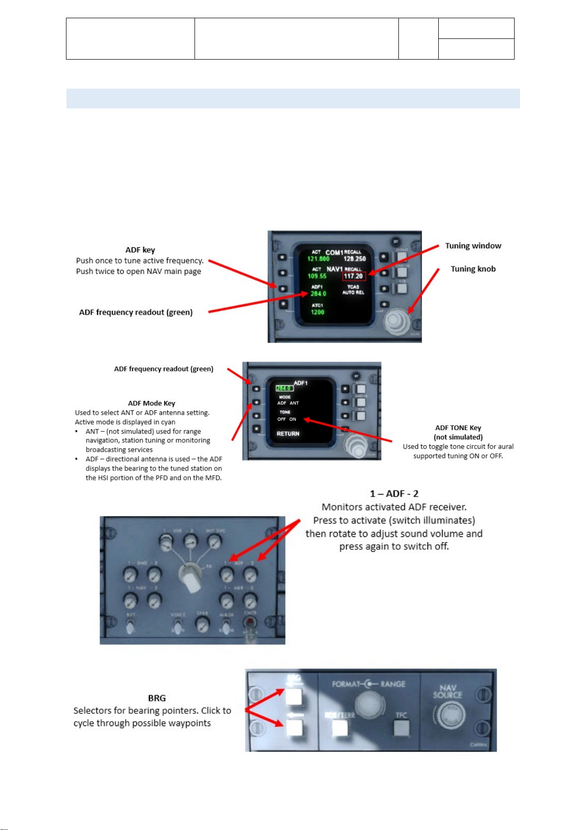
Aerosoft – Digital Aviation
CRJ-70 & CRJ-900
AOM PART 2
Systems Description
VOL
5
5-1-100
26-Jul-2017
AUTO M A TIC DI R ECTION FI NDER (AD F )
The ADF system is used to display the bearing from the aircraft to a ground station. The ground station may
either be a non-directional beacon (NDB) or a standard amplitutde modulation (AM) broadcast station sending
within the frequency range of 190.0 to 1799,5 kHz.
The CRJ has two ADF receivers ADF 1 and ADF 2 which may be operated independently.
Bearing selection is made on the pilot or copilots display control panel (DCP) whereas the bearing-to-station
data is displayed in the HSI section of the PFD or on the MFDs.
 Loading...