


|
Aerosoft – Digital Aviation |
|
|
AOM PART 2 |
VOL |
5-1-1 |
||
|
CRJ-700 CRJ-900 |
|
|
Revision Info |
5 |
26-Jul-2017 |
||
|
|
|
|
|
|
|
|
|
|
|
|
|
|
|
|
|
|
|
Rev # |
Date |
Author |
Change |
|
|
Version |
|
|
001 |
11-Oct-15 |
IV |
Start of documentation |
|
|
0.90 |
|
|
002 |
31-Dec-16 |
MK |
Updating to new software |
|
|
0.92 |
|
|
003 |
20- Apr-17 |
MK |
Finalizing |
|
|
1.00 |
|
|
004 |
01-May-17 |
MK |
Updating to latest files |
|
|
1.00 |
|
|
|
|
|
|
|
|
|
|
|
|
|
|
|
|
|
|
|
|
|
|
|
|
|
|
|
|
|
|
|
|
|
|
|
|
|
|
|
|
|
|
|
|
|
|
|
|
|
|
|
|
|
|
|
|
|
|
|
|
|
|
|
|
|
|
|
|
|
|
|
|
|
|
|
|
|
|
|
|
|
|
|
|
|
|
|
|
|
|
|
|
|
|
|
|
|
|
|
|
On behalf of Authority
|
Aerosoft – Digital Aviation |
|
AOM PART 2 |
|
VOL |
|
5-1-2 |
|
|
|
CRJ-70 & CRJ-900 |
|
Systems Description |
|
5 |
|
26-Jul-2017 |
|
|
|
|
|
|
|
|
|
|
|
|
|
|
|
|
|
|
|
|
|
|
|
TABLE OF CONTENTS |
|
|
|
|
|
|
|
|
|
|
|
|
|
|
|
|
||
|
AUXILLIARY POWER UNIT ..................................................................................................................... |
|
|
|
|
|
5 |
||
|
AURAL/VISUAL INDICATING & RECORDING .......................................................................................... |
|
|
|
6 |
||||
|
EICAS CONTROL PANEL ..................................................................................................................... |
|
|
|
|
|
7 |
||
|
DISPLAY REVERSION.......................................................................................................................... |
|
|
|
|
|
8 |
||
|
AURAL WARNINGS / AUDIO SIGNALS |
............................................................................................... |
|
|
|
|
9 |
||
|
MASTER WARNING LIGHT................................................................................................................. |
|
|
|
|
|
9 |
||
|
MASTER CAUTION LIGHT ................................................................................................................ |
|
|
|
|
|
10 |
||
|
CREW ALERTING SYSTEM (CAS) .................................................................................................. |
|
|
|
|
|
10 |
||
|
TAKE-OFF WARNING ....................................................................................................................... |
|
|
|
|
|
13 |
||
|
LANDING CONFIG WARNING .......................................................................................................... |
|
|
|
|
|
14 |
||
|
MENU PAGE .................................................................................................................................... |
|
|
|
|
|
15 |
||
|
FLIGHT DATA RECORDER..................................................................................................................... |
|
|
|
|
|
15 |
||
|
AUTOMATIC FLIGHT CONTROL SYSTEM.............................................................................................. |
|
|
|
|
|
15 |
||
|
FLIGHT DIRECTOR............................................................................................................................ |
|
|
|
|
|
16 |
||
|
FLIGHT MODE ANNUNCIATOR – LATERAL MODES.......................................................................... |
|
|
|
17 |
||||
|
FLIGHT MODE ANNUNCIATOR – VERTICAL MODES ........................................................................ |
|
|
|
18 |
||||
|
SYNCHRONIZATION......................................................................................................................... |
|
|
|
|
|
20 |
||
|
ALTITUDE ALERT SYSTEM.................................................................................................................... |
|
|
|
|
|
20 |
||
|
AUTOPILOT ......................................................................................................................................... |
|
|
|
|
|
21 |
||
|
COMMUNICATIONS ............................................................................................................................ |
|
|
|
|
|
22 |
||
|
AUDIO CONTROL PANEL ................................................................................................................. |
|
|
|
|
|
22 |
||
|
INTERPHONE AND INTERCOM CONTROL PANEL............................................................................. |
|
|
|
23 |
||||
|
RADIO TUNING UNIT (RTU)............................................................................................................. |
|
|
|
|
|
23 |
||
|
COMS MENU................................................................................................................................... |
|
|
|
|
|
24 |
||
|
TCAS MENU..................................................................................................................................... |
|
|
|
|
|
24 |
||
|
BACKUP TUNING UNIT .................................................................................................................... |
|
|
|
|
|
25 |
||
|
ELECTRICAL ......................................................................................................................................... |
|
|
|
|
|
25 |
||
|
ALTERNATING CURRENT, AC SYSTEM ............................................................................................. |
|
|
|
|
|
26 |
||
|
CONTROLS ON OVERHEAD PANEL .............................................................................................. |
|
|
|
|
|
28 |
||
|
EICAS SYNOPTIC PAGE – HOW TO OPEN AC & DC ELECTRICAL SYNOPTIC PAGES ....................... |
|
29 |
||||||
|
EICAS SYNOPTIC PAGE – ELECTRICAL POWER SUPPLIED FROM ENGINES................................... |
|
|
|
29 |
||||
|
EICAS SYNOPTIC PAGE – ELECTRICAL POWER SUPPLIED FROM AIR DRIVEN GENERATOR.......... |
30 |
|||||||
|
EICAS SYNOPTIC PAGE – ELECTRICAL POWER SUPPLIED FROM EXTERNAL POWER.................... |
|
31 |
||||||
|
EICAS MESSAGES............................................................................................................................. |
|
|
|
|
|
31 |
||
|
DIRECT CURRENT, DC SYSTEM ........................................................................................................ |
|
|
|
|
|
32 |
||
|
EICAS MESSAGES......................................................................................................................... |
|
|
|
|
|
33 |
||
|
ENVIRONMENTAL CONTROL SYSTEM ................................................................................................. |
|
|
|
|
|
36 |
||
|
AIR CONDITIONING SYSTEM / PACKS.............................................................................................. |
|
|
|
|
|
36 |
||
|
ECAM MESSAGES ........................................................................................................................ |
|
|
|
|
|
37 |
||
|
AVIONICS COOLING SYSTEM ....................................................................................................... |
|
|
|
|
|
37 |
||
|
ECAM MESSAGES ........................................................................................................................ |
|
|
|
|
|
38 |
||
|
CABIN PRESSURIZATION SYSTEM.................................................................................................... |
|
|
|
|
|
38 |
||
|
ECAM MESSAGES ........................................................................................................................ |
|
|
|
|
|
38 |
||
|
PRESSURIZATION MODES – AUTOMATIC MODES....................................................................... |
|
|
|
40 |
||||
|
PRESSURIZATION MODES – MANUAL MODES ............................................................................ |
|
|
|
40 |
||||
|
SAFETY VALVES ........................................................................................................................... |
|
|
|
|
|
41 |
||
|
GROUND VALVE .......................................................................................................................... |
|
|
|
|
|
41 |
||
|
CABIN ALTITUDE LIMIT................................................................................................................ |
|
|
|
|
|
41 |
||
|
EMERGENCY DEPRESSURIZATION............................................................................................... |
|
|
|
|
|
41 |
||
Aerosoft – Digital Aviation |
|
AOM PART 2 |
VOL |
5-1-3 |
CRJ-70 & CRJ-900 |
|
Systems Description |
5 |
26-Jul-2017 |
|
|
|
|
|
EMERGENCY EQUIPMENT................................................................................................................... |
|
|
42 |
|
FIRE PROTECTION ............................................................................................................................... |
|
|
43 |
|
ENGINE FIRE CONTROLS & MESSAGES |
............................................................................................ |
|
43 |
|
ECAM MESSAGE.......................................................................................................................... |
|
|
43 |
|
APU FIRE CONTROLS & MESSAGES ................................................................................................. |
|
|
46 |
|
CARGO COMPARTMENT FIRE CONTROLS & MESSAGES.................................................................. |
|
46 |
||
ECAM MESSAGES ........................................................................................................................ |
|
|
46 |
|
FIRE SYSTEM TEST ........................................................................................................................... |
|
|
46 |
|
MAIN LANDING GEAR OVERHEAT DETECTION................................................................................ |
|
47 |
||
FLIGHT CONTROLS .............................................................................................................................. |
|
|
48 |
|
AILERONS........................................................................................................................................ |
|
|
49 |
|
RUDDER .......................................................................................................................................... |
|
|
50 |
|
ELEVATOR ....................................................................................................................................... |
|
|
51 |
|
HORIZONTAL STABILIZER TRIM ....................................................................................................... |
|
|
52 |
|
FLAPS AND SLATS............................................................................................................................ |
|
|
53 |
|
SPOILERS ......................................................................................................................................... |
|
|
54 |
|
STALL PROTECTION SYSTEM ........................................................................................................... |
|
|
55 |
|
FLIGHT INSTRUMENTS ........................................................................................................................ |
|
|
56 |
|
ELECTRONIC FLIGHT INSTRUMENT SYSTEM (EFIS) .......................................................................... |
|
57 |
||
DISPLAY REVERSION........................................................................................................................ |
|
|
58 |
|
DISPLAY CONTROL .......................................................................................................................... |
|
|
58 |
|
AIR DATA SYSTEM ........................................................................................................................... |
|
|
59 |
|
PITOT STATIC SYSTEM ..................................................................................................................... |
|
|
59 |
|
AIR DATA......................................................................................................................................... |
|
|
59 |
|
AIR DATA REFERENCE (ARP) PANELS............................................................................................... |
|
|
60 |
|
ALTITUDE ALERTS............................................................................................................................ |
|
|
63 |
|
LOW SPEED CUE.............................................................................................................................. |
|
|
63 |
|
AIR DATA REVERSION...................................................................................................................... |
|
|
63 |
|
RADIO ALTIMETER SYSTEM............................................................................................................. |
|
|
64 |
|
INERTIAL REFERENCE SYSTEM......................................................................................................... |
|
|
65 |
|
DISPLAY REVERSION.................................................................................................................... |
|
|
66 |
|
STANDBY INSTRUMENTS AND CLOCKS ........................................................................................... |
|
67 |
||
INTEGRATED STANDBY INSTRUMENT ......................................................................................... |
|
67 |
||
STANDBY COMPASS .................................................................................................................... |
|
|
68 |
|
CLOCKS........................................................................................................................................ |
|
|
69 |
|
FUEL SYSTEM ...................................................................................................................................... |
|
|
70 |
|
FUEL TANKS / STORAGE .................................................................................................................. |
|
|
70 |
|
FUEL MANAGEMENT (TRANSFER/CROSSFLOW) & DISTRIBUTION.................................................. |
|
70 |
||
FUEL QUANTITY GAUGING.............................................................................................................. |
|
|
72 |
|
HYDRAULIC POWER ............................................................................................................................ |
|
|
74 |
|
ICE & RAIN PROTECTION..................................................................................................................... |
|
|
77 |
|
ICE DETECTION SYSTEM .................................................................................................................. |
|
|
78 |
|
WING AND COWL ANTI-ICE SYSTEM ............................................................................................... |
|
|
79 |
|
AIR DATA ANTI-ICE SYSTEM ............................................................................................................ |
|
|
80 |
|
WINDSHIELD AND SIDE WINDOW ANTI-ICE SYSTEM ...................................................................... |
|
81 |
||
WINDSHIELD WIPER SYSTEM .......................................................................................................... |
|
|
81 |
|
LANDING GEAR ................................................................................................................................... |
|
|
82 |
|
BRAKE SYSTEM................................................................................................................................ |
|
|
83 |
|
PARKING BRAKE .......................................................................................................................... |
|
|
83 |
|
BRAKE TEMPERATURE MONITORING SYSTEM............................................................................ |
|
84 |
||
ANTI-SKID.................................................................................................................................... |
|
|
85 |
|
NOSE WHEEL STEERING SYSTEM................................................................................................. |
|
|
86 |
|
Aerosoft – Digital Aviation |
|
AOM PART 2 |
VOL |
5-1-4 |
CRJ-70 & CRJ-900 |
|
Systems Description |
5 |
26-Jul-2017 |
|
|
|
|
|
LIGHTING ............................................................................................................................................ |
|
|
87 |
|
COCKPIT LIGHTING.......................................................................................................................... |
|
|
87 |
|
PASSENGER COMPARTMENT LIGHTING.......................................................................................... |
|
88 |
||
EXTERNAL LIGHTING ....................................................................................................................... |
|
|
89 |
|
EMERGENCY LIGHTING ................................................................................................................... |
|
|
91 |
|
NAVIGATION SYSTEMS........................................................................................................................ |
|
|
91 |
|
FLIGHT MANAGEMENT SYSTEM (FMS) ........................................................................................... |
|
92 |
||
WHERE TO FIND THE FMS/CDU AND BASIC LAYOUT ...................................................................... |
|
92 |
||
PREFLIGHT SETUP AND SEQUENCE OF PAGES ................................................................................ |
|
96 |
||
GLOBAL POSITIONING SYSTEM (GPS) |
.............................................................................................. |
|
97 |
|
VHF NAVIGATION............................................................................................................................ |
|
|
97 |
|
AUTOMATIC DIRECTION FINDER (ADF) ......................................................................................... |
|
100 |
||
DISTANCE MEASURING EQUIPMENT (DME) ................................................................................. |
|
101 |
||
AIR TRAFFIC CONTROL TRANSPONDER SYSTEM (ACT).................................................................. |
|
103 |
||
TRAFFIC ALERT AND COLLISION AVOIDANCE SYSTEM (TCAS) ....................................................... |
|
104 |
||
TRAFFIC ADVISORY (TA) ............................................................................................................ |
|
|
106 |
|
RESOLUTION ADVISORY (RA) .................................................................................................... |
|
|
106 |
|
AURAL WARNING...................................................................................................................... |
|
|
107 |
|
GROUND PROXIMITY WARNING SYSTEM (GPWS) ........................................................................ |
|
107 |
||
MODE 1 – EXCESSIVE DESCENT RATE........................................................................................ |
|
109 |
||
MODE 2 – EXCESSIVE TERRAIN CLOSURE RATE......................................................................... |
|
109 |
||
MODE 3 – ALTITUDE LOSS AFTER TAKE-OFF ............................................................................. |
|
109 |
||
MODE 4 – UNSAFE TERRAIN CLEARANCE.................................................................................. |
|
110 |
||
MODE 5 – BELOW GLIDESLOPE ALERT ...................................................................................... |
|
110 |
||
MODE 6 – CALLOUTS (DESCENT BELOW MINIMUM, ALTITUDE CALLOUTS AND BANK ANGLE |
||||
ALERT)....................................................................................................................................... |
|
|
110 |
|
MODE 7 –WINDSHEAR DETECTION AND ALERTING.................................................................. |
|
110 |
||
TERRAIN / OBSTACLE AWARENESS ALERTING AND DISPLAY .................................................... |
|
112 |
||
WEATHER RADAR (WXR)............................................................................................................... |
|
|
113 |
|
POWER PLANT .................................................................................................................................. |
|
|
114 |
|
THRUST CONTROL......................................................................................................................... |
|
|
115 |
|
FULL AUTHORITY DIGITAL ELECTRONIC CONTROL (FADEC) .......................................................... |
|
117 |
||
FLEX POWER ................................................................................................................................. |
|
|
118 |
|
AUTOMATIC POWER RESERVE (APR) ............................................................................................ |
|
|
118 |
|
HIGH POWER SCHEDULE ........................................................................................................... |
|
|
119 |
|
N1 AND N2 SYNCHRONISATION ..................................................................................................... |
|
|
119 |
|
ENGINE OVERSPEED PROTECTION ................................................................................................ |
|
|
119 |
|
ENGINE N2 INDICATIONS WHEN USING WING ANTI-ICE ............................................................... |
|
119 |
||
STARTING AND IGNITION SYSTEM ................................................................................................ |
|
|
119 |
|
OIL SYSTEM ................................................................................................................................... |
|
|
121 |
|
FUEL SYSTEM ................................................................................................................................ |
|
|
122 |
|
INTERTURBINE TEMPERATURE (ITT) MONITORING ...................................................................... |
|
123 |
||
VIBRATION MONITORING ............................................................................................................. |
|
|
123 |
|
REVERSE THRUST .......................................................................................................................... |
|
|
124 |
|
PNEUMATICS .................................................................................................................................... |
|
|
125 |
|

Aerosoft – Digital Aviation |
AOM PART 2 |
VOL |
5-1-5 |
CRJ-70 & CRJ-900 |
Systems Description |
5 |
26-Jul-2017 |
|
|
|
|
AUXILLIARY POWER UNIT
The CRJ700 and CRJ900 are both equipped with an Allied Signal RE 220 (RJ) auxiliary power unit (APU). The APU is technically a gas-turbine and it is used to provide electrical power and even more important compressed air.
The APU is basically comprised of three stages: a compressor followed by a combustion chamber and a turbine. The APU is started by an electrical motor which rotates the APUs main shaft until it gained enough speed so that fuel can be injected into the combustion chamber. The fuel burns and hence tries to expand which accelerates the air even further. The turbine on the other hand drives a generator – so the turbine converts the accelerated airflow into electrical power. As you can see the basic principle of an APU and an aircraft engine are technical the same. The major difference is that the APU is not used to produce thrust therefore APUs are also much smaller than aircraft engines.
Apart from electrical power, bleed air is also drawn from the APU to supply the packs or also the engine starters (the aircrafts engines are usually started with pneumatic air).
Thus, it is mainly use during aircraft preparation and engine start. Nevertheless, it may also be used as a backup once an engine failed / was switched off.
The air-inlet-flap of the APU is used to control airflow into the APU. The flaps position is controlled automatically by the built-in electronics.
Aerosoft – Digital Aviation |
AOM PART 2 |
VOL |
5-1-6 |
CRJ-70 & CRJ-900 |
Systems Description |
5 |
26-Jul-2017 |
|
|
|
|
AURAL/VISUAL INDICATING & RECORDING
All aircraft systems do have sensors to detect abnormal settings or behaviour. All systems – including the engines – report this information to two central processing units: the data concentrator units (1 & 2). The interface to the pilots is the engine indication and crew alerting system (EICAS). Certain messages do also trigger audio signals or trigger the master warning or master caution light.
The EICAS is comprised of two units – called EICAS Display 1 & 2 (ED1 and ED2) – basically the
left and the right EICAS display: The left EICAS is called ED1 and the right EICAS ED2.
Normally ED1 displays the primary page and ED2 displays the status page. The EICAS control panel on the lower pedestal enables the pilots to select if the primary, the secondary or a synoptic page is displayed on either ED. Please us the display reversion control panels to change whether the primary or secondary is displayed on ED1 or ED2 respectively. The EICAS source selector panel allows the pilot to select where all EICAS information is displayed. You may choose between ED1 or ED2 or both (default).
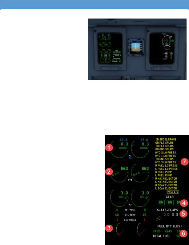
The EICAS primary page displays the following information:
1.Engine compressor and turbine speeds (N1 and N2 rpm)
2.Engine temperature (ITT)
3.Fuel flow (FF)
Oil pressure and temperature Engine vibration data
4.Landing gear position
5.Slat/flap position
6.Fuel tank quantities and total fuel
7.Crew alerting system (CAS) messages in the form of red warning and amber caution messages
Aerosoft – Digital Aviation |
AOM PART 2 |
VOL |
5-1-7 |
CRJ-70 & CRJ-900 |
Systems Description |
5 |
26-Jul-2017 |
|
|
|
|
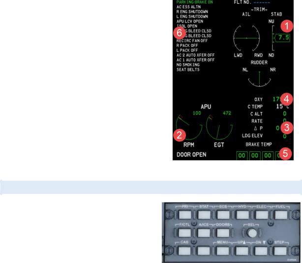
The EICAS status page displays the following information:
1.Flight control trim indications
2.Auxiliary power unit (APU) indications such as APU RPM, exhaust gas temperature (EGT) and APU inlet door status
3.Pressurization data such as cabin altitude, cabin rate of change, cabin pressure differential, and landing field elevation
4.Oxygen system pressure
5.Brake system temperature readouts
6.Crew alerting system (CAS) messages in the form of green advisory and white status messages
•Aircraft systems synoptic pages (via the EICAS control panel)
See next section for more details
•MENU page (via the EICAS control panel) allows reset of the fuel used indicator and displays the engine oil quantity
See respective section of this chapter.
EICAS CONTROL PANEL
The EICAS Control Panel enables you to open the different aircraft system synoptic pages.
The panel itself is found on the upper pedestal. The following pushbuttons, respective system pages are available:
•PRI: Opens Primary Page (normally displayed on ED1) on secondary display (ED2)
•STAT: Displays Status Page. A second push removes all status messages / open further status messages if several pages of status messages exist.
•Synoptic Pages
o ECS: Opens Environmental Control System page o HYD: Opens Hydraulic system page
o ELEC: Opens Electrical system page o FUEL: Opens Fuel system page
o F/CTL: Open Flight Controls system page o A/ICE: Opens Anti-Ice system page
o DOORS: Opens Door system page
oMENU: Opens the menu page
•SEL: Selector – used to activate a selected item. A change in colour will indicate selection
•CAS: Removes caution messages from primary display. Previously invisible messages get displayed
•UP: Controls cursor
•DN: Controls cursor
•STEP: Steps through pages of secondary page if available
Aerosoft – Digital Aviation |
AOM PART 2 |
VOL |
5-1-8 |
CRJ-70 & CRJ-900 |
Systems Description |
5 |
26-Jul-2017 |
|
|
|
|
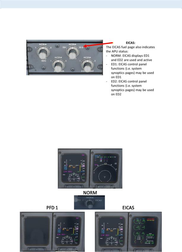
DISPLAY REVERSION
In case EICAS display ED1 fails, ED2 will automatically switch to primary page. In case EICAS display ED2 fails, there is no automatic switch. With either display failed, the EICAS control panel is rendered inoperative. Please switch the EICAS selector on the SOURCE SELECTOR PANEL to the operative display (ED1 or ED2). This reenables you to select and display the EICAS information on the selected display.
Furthermore, a revisionary panel is installed on either pilot’s side panel. They offer three positions:
•PFD 1, respective PFD 2
Switches the respective primary flight display (PFD1 = pilot, PFD 2 = co-pilot) to the adjacent MFD.
•NORM
PFD and MFD in normal operation
•EICAS
Shows the EICAS ED1 display on the MFD.
|
|
Aerosoft – Digital Aviation |
|
AOM PART 2 |
VOL |
5-1-9 |
|
||
|
|
CRJ-70 & CRJ-900 |
|
Systems Description |
5 |
26-Jul-2017 |
|
||
|
|
|
|
|
|
|
|
|
|
|
|
|
|
|
|
|
|
|
|
|
|
AURAL WARNINGS / AUDIO SIGNALS |
|
|
|
|
|
||
|
|
|
|
|
|
|
|
||
|
|
The following table shows the available aural warnings / audio signals. |
|
|
|
||||
|
|
|
|
|
|
|
|
|
|
|
|
Sound |
Indication |
|
|
|
|
|
|
|
|
Warbler |
Stall |
|
|
|
|
|
|
|
|
Windshear |
Windshear |
|
|
|
|
|
|
|
|
Whoop – Whoop |
GPWS (excessive descent or closure rate) |
|
|
|
|
||
|
|
Fire bell |
Fire warnings |
|
|
|
|
|
|
|
|
Clacker |
Excessive stabilizer trim Movement |
|
|
|
|
||
|
|
|
VMO/MMO exceedance |
|
|
|
|
||
|
|
|
Airspeed too high for current flap setting |
|
|
|
|
||
|
|
Cavalry Charge |
Autopilot disconnect |
|
|
|
|
|
|
|
|
Horn |
Gear warning (not down) |
|
|
|
|
||
|
|
Triple chime |
Warning tone (indicates an aircraft system voice advisory) |
|
|
|
|
||
|
|
C-chord |
Altitude alert |
|
|
|
|
|
|
|
|
Single chime |
Caution tone (indicates an aircraft system voice advisory) |
|
|
|
|
||
Faulty aural warnings may result from a defective DCU. There are two guarded pushbuttons on the co-pilots side panel – called the audio warning panel – to switch off the affected DCU. Open the guard and press the pushbutton to deactivate the DCU. Switching a DCU off triggers respective EICAS messages and the pushbutton will illuminate white.
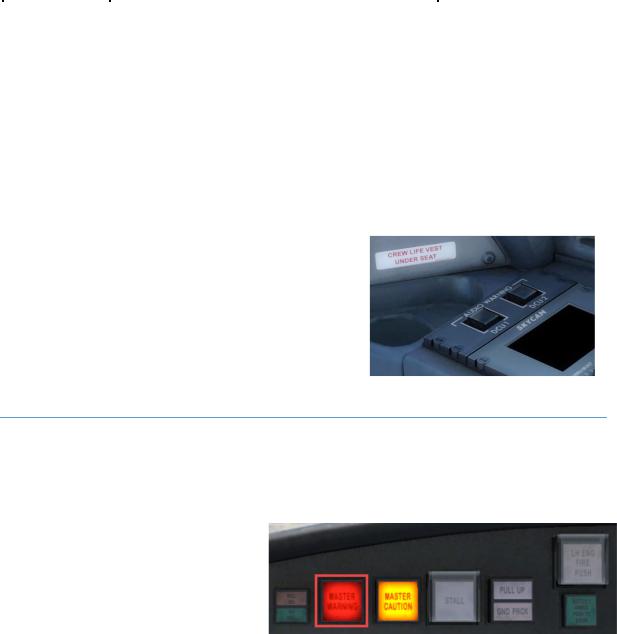
MASTER WARNING LIGHT
There is a master warning light on either side – the pilot’s and the co-pilot’s side. In case a warning is triggered, both lights come on and stay flashing if the warning exists or the warning light is pushed by the pilot or copilot. The aural warning and flashing light stay off until the next warning is triggered.
In the following cases the aural warning may not be muted:
•Stall warbler
•Stabilizer trim clacker
•GPWS/TCAS (voices and aural)
•AP Disconnect cavalry charge
•Overspeed clacker
•Configuration warnings
•Flap clacker
•Gear Horn

Aerosoft – Digital Aviation |
AOM PART 2 |
VOL |
5-1-10 |
CRJ-70 & CRJ-900 |
Systems Description |
5 |
26-Jul-2017 |
|
|
|
|
MASTER CAUTION LIGHT
Positioned right next to the master warning light is the master caution light. It works the same way the master warning light does.
In the following two cases the master caution may not be muted:
•GPWS and TCAS voice alerts
•Altitude alert (C-chord) aural
CREW ALERTING SYSTEM (CAS)
All warning / caution messages are sorted by priority / urgency and order of occurrence. The CAS works with four categories of messages, with different colour codes and behaviour, indicated in the following table.
In case the triggering condition / fault is removed the message will disappear from the EICAS again. New messages are added on top according their priority / category.
If the number of message exceeds the available lines in the EICAS, the message “PAGE 1/2” appears in red. All further messages are available on the following page(s). Press the CAS button to access the messages on the second side.
When messages are excluded from view by pressing the CAS button a “MSGS” message appears in the EICAS reminding the crew of the excluded messages. Same goes for advisories and status messages on the STAT page.
Category |
Aural |
Master warning / |
Color |
Sort order |
Displayed |
Removeable |
|
Warning |
master caution |
code |
|
on ED1 / |
from EICAS? |
|
|
|
|
|
ED2 |
|
Warning |
Triple chime |
Master warning |
Red |
top |
ED1 |
No |
|
Or voice |
|
|
|
|
|
Caution |
Single chime |
Master caution |
amber |
Below |
ED1 |
Yes – CAS |
|
|
|
|
warnings |
|
button |
Advisory |
No |
No |
Green |
Top of ED2 |
ED2 |
No – unless |
|
|
|
|
|
|
condition is |
|
|
|
|
|
|
removed |
Status |
No |
No |
White |
Below |
ED2 |
Yes – STAT |
|
|
|
|
advisory |
|
button |
Aerosoft – Digital Aviation |
AOM PART 2 |
VOL |
5-1-11 |
CRJ-70 & CRJ-900 |
Systems Description |
5 |
26-Jul-2017 |
|
|
|
|
To reduce information during flight phases with high stress level, the DCUs filter information:
Inhibit |
Inhibit is enabled when: |
Inhibit is removed when: |
||
|
|
|
|
|
Initial take-off |
• |
Left and right engine N1 is greater than |
• |
Left and right engine N1 is less than |
|
|
79%, |
|
67.6%, or |
|
• |
weight-on-wheels, and airspeed is less |
• |
Airplane is in the final take-off phase |
|
|
than 100 knots. |
|
|
|
|
|
|
|
Final take-off |
• |
Left and right engine N1 is greater |
• |
Left and right engine N1 is less than |
|
|
than 79%, and |
|
67.6%, or |
|
• |
airspeed transitions to greater than |
• |
Radio altitude is greater than 400 ft |
|
|
100 knots. |
|
AGL, or |
|
|
|
• |
30 seconds after ground to air |
|
|
|
|
transition. |
|
|
|
|
|
|
Aircraft System |
Warning Message |
|
|
Aural |
|
||
|
|
(Inhibited during take-off) |
|
(Inhibited during take-off) |
||||
|
|
|
|
|
|
|
|
|
|
Environmental Control |
|
|
|
|
|
CABIN ALT Cabin Pressure |
|
|
|
|
|
|
|
|
|
|
|
System |
|
|
|
|
|
|
|
|
|
|
|
|
|
|
|
|
|
Flight Controls |
|
|
|
|
|
Overspeed Clacker |
|
|
|
|
|
|
|
|
|
|
|
Landing Gear |
• |
GEAR DISAGREE |
|
• |
Gear Disagree |
||
|
|
|
Nose Door |
|||||
|
|
• |
NOSE DOOR OPEN |
• |
||||
|
|
|
|
|||||
|
|
|
|
|
|
|
||
Landing |
• Radio altitude transitions to less than |
|
• |
30 seconds after air to ground |
||||
|
400 ft AGL, and |
|
|
|
|
transition or |
|
|
|
• landing gear down and locked. |
|
• |
Radio altitude transitions from less |
||||
|
|
|
|
|
|
than 400 ft to greater than 400 ft. |
||
|
|
|
|
|
|
|
|
|
|
Aircraft System |
Warning Message |
|
|
Aural |
|
||
|
|
(Inhibited during take-off) |
|
(Inhibited during take-off) |
||||
|
|
|
|
|
|
|
||
|
Auxiliary Power Unit |
APU OVERTEMP |
|
|
APU |
|
||
|
|
|
|
|
|
|
|
|
|
|
|
|
|
|
|
||
|
Doors |
PASSENGER DOOR |
|
|
Door |
|
||
|
|
|
|
|
|
|
|
|
|
Environmental Control |
• |
CABIN ALT |
|
|
• |
Cabin Pressure |
|
|
|
|
|
|
|
|
|
|
|
System |
• |
DIFF PRESS |
|
|
• |
Cabin Pressure |
|
|
|
|
|
|
|
|
|
|
|
Ice and Rain Protection |
• ANTI-ICE DUCT |
|
• |
Anti-Ice Duct |
|||
|
|
|
|
Anti-Ice Duct |
||||
|
|
• L COWL A/I DUCT |
|
• |
||||
|
|
|
|
Anti-Ice Duct |
||||
|
|
• R COWL A/I DUCT |
• |
|||||
|
|
|
Wing Overheat |
|||||
|
|
• |
WING OVHT |
|
|
• |
||
|
|
|
|
|
|
|||
|
|
|
|
|
|
|||
|
Landing Gear |
NOSE DOOR OPEN |
|
|
Node Door |
|||
|
|
|
|
|
|
|||
|
Power Plant |
• L ENG OIL PRESS |
|
• |
Engine Oil |
|||
|
|
• R ENG OIL PRESS |
|
• |
Engine Oil |
|||
|
|
|
|
|
|
|
|
|

Aerosoft – Digital Aviation |
AOM PART 2 |
VOL |
5-1-12 |
CRJ-70 & CRJ-900 |
Systems Description |
5 |
26-Jul-2017 |
|
|
|
|
In a similar fashion the cautions are inhibited as well. There are several caution messages which are not inhibited though:
Airplane system |
Caution message (not inhibited) |
|
|
|
|
|
|
|
|
Automatic Flight Control System |
YAW DAMPER |
|
|
|
|
|
|
|
|
Auxiliary Power Unit |
APU LCV CLSD |
|
|
|
|
|
|
||
|
|
|
|
|
Fire Protection |
FIRE SYS FAULT |
|
|
|
|
|
|
||
|
|
|
|
|
Flight Controls |
• |
GLD NOT ARMED |
• |
PITCH FEEL |
|
|
RUD LIMITER |
||
|
• |
GLD UNSAFE |
• |
|
|
|
SLATS FAIL |
||
|
• |
GND SPLR DEPLOY |
• |
|
|
|
SPOILERONS ROLL |
||
|
• |
IB (OB) FLT SPLRS |
• |
|
|
|
STAB TRIM |
||
|
• |
IB (OB) GND SPLRS |
• |
|
|
|
STAB TRIM LIMIT |
||
|
• |
IB (OB) SPOILERONS |
• |
|
|
• |
STALL FAIL |
||
|
|
|
||
|
|
|
|
|
Flight Instruments |
EFIS COMP MON |
|
|
|
|
|
|
||
|
|
|
|
|
Hydraulic Power |
HYD 1 (2) (3) LO PRESS |
|
|
|
|
|
|
|
|
|
• |
ICE |
• L (R) COWL A/I OPEN |
|
|
• L (R) WING A/I |
|||
|
• |
ICE DET FAIL |
||
|
|
|
||
|
|
|
|
|
Landing Gear |
• |
A/SKID INBD (OUTBD) |
|
|
|
|
|
||
|
• IB (OB) BRAKE PRESS |
|
|
|
|
• |
PROX SYSTEM |
|
|
|
• |
WOW INPUT (OUTPUT) |
|
|
|
|
|
|
|
Pneumatic |
• ANTI-ICE DUCT |
|
|
|
|
|
|
||
|
• L (R) BLEED DUCT |
|
|
|
|
• L (R) COWL LOOP |
|
|
|
|
|
|
|
|
Power Plant |
• L (R) ENG FLAMEOUT |
|
|
|
|
|
|
||
|
• L (R) ENG SRG CLSD |
|
|
|
|
• |
L (R) FADEC |
|
|
|
• L (R) FADEC OVHT |
|
|
|
|
• L (R) REV INOP |
|
|
|
|
• L (R) REV UNLOCKED |
|
|
|
|
• L (R) REV UNSAFE |
|
|
|
|
|
|
|
|

Aerosoft – Digital Aviation |
AOM PART 2 |
VOL |
5-1-13 |
CRJ-70 & CRJ-900 |
Systems Description |
5 |
26-Jul-2017 |
|
|
|
|
TAKE-OFF WARNING
A lot of aircraft do have take-off configuration warning. The actuals aircraft is checked according a pre-defined logic and in case a deviation is recognized, the crew is informed. The CRJ does this automatically as soon as the engines are accelerated beyond 70% N1.
The following systems / conditions are checked:
Condition |
Voice Message |
EICAS Message |
Autopilot engaged |
Config autopilot |
CONFIG AP |
Flaps not in take-off position |
Config flaps |
CONFIG FLAPS |
All spoilers not in take-off position |
Config spoilers |
CONFIG SPLRS |
(down) |
|
|
Horizontal stabilizer outside take-off |
Config trim |
CONFIG STAB |
range (green band) |
|
|
Parking brake set |
Config Brakes |
PARKING BRAKE SET |
Rudder trim outside of take-off |
Config trim |
CONFIG RUDDER |
range (trim > ±1 degree) |
|
|
Aileron trim outside of take-off range |
Config trim |
CONFIG AILERON |
(trim > ±1 degree) |
|
|
If the aircraft detects a deviation it is considered unsafe for take-off. Aural and warning messages will indicate if such a condition is detected. Furthermore, both MASTER WARNING lights come on.
As soon as the triggering system is corrected, the warning is silenced.

Aerosoft – Digital Aviation |
AOM PART 2 |
VOL |
5-1-14 |
CRJ-70 & CRJ-900 |
Systems Description |
5 |
26-Jul-2017 |
|
|
|
|
LANDING CONFIG WARNING
Like the take-off configuration the landing configuration is automatically checked, too. A deviation will be indicated by the landing gear horn. Two minutes after lift-off (ground to air transition) the mechanism is armed and will sound if one of the following conditions exists:
•Radio altitude < 500 ft
•Both throttles at less than maximum landing setting OR
•Flaps > 30°
OR
•Both throttles at less than maximum landing setting OR
•Any one throttle is at IDLE with the landing gear warning horn muted
AND
•Airspeed < 170 kts
•Flaps > 30° OR
•Airspeed < 190 kts
•Flats / slats = 0
AND
•Radio altimeter OR throttle is not valid
OR
•Radio altitude is less than 1000 ft AGL
•vertical speed less than -400 ft/min
AND
•No windshear warning or a windshear warning with a windshear monitor failure
OR
•Radio altitude is less than 1000 ft AGL
•vertical speed OR GPWS not valid
The “Too low gear” aural warning is heard if:
•any landing gear is not down and locked
•radio altitude less than 500 ft AGL
•indicated airspeed at less than 190 knots.
Aerosoft – Digital Aviation |
AOM PART 2 |
VOL |
5-1-15 |
CRJ-70 & CRJ-900 |
Systems Description |
5 |
26-Jul-2017 |
|
|
|
|
MENU PAGE
The MENU page is divided into three sections: menu section, confirmation section and parameter readout. A cursor on the left side of the screen is controlled by the UP/DN buttons on the EICAS control panel (ECP). The SELECT button on the ECP is used to select a line item.
The menu list contains a single FUEL USED RESET line. When the line is selected, the ACCEPT/CANCEL selections in the confirmation section are used to accept or cancel the request to reset to zero the “Fuel Used” indication, on the FUEL synoptic page.
The parameter readouts section contains the engine OIL LEVEL indications.
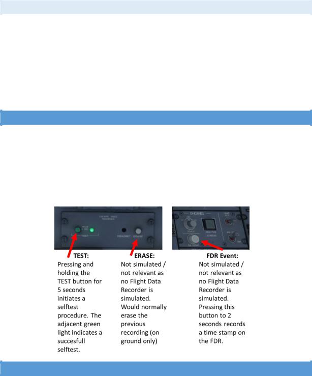
FLIGHT DATA RECORDER
Real aircraft are equipped with flight data and voice recorders. The CRJ’s flight data recorder saves different information for 25hrs of flight. The FDR automatically starts recording as soon as the BEACON light, STROBE light is switched ON or a take-off-like condition is detected via the wheels. In case the pilots want to mark a certain event, they can push the FDR event button for 2 seconds and a timestamp is saved.
The voice recorder saves the last 120 minutes of cockpit communication and passenger announcements as soon as the aircraft is powered up.
AUTOMATIC FLIGHT CONTROL SYSTEM
The automatic flight control system consists of several systems:
•Flight Director
•Autopilot
•Flight control computers
•Two yaw dampers
•Automatic elevator trim
•Servos / actuators
The flight director computes a flight path which needs to be followed to archive certain pre-set constraints (i.e. climb at a pre-defined speed to a pre-set altitude). The autopilot computes the required flight control’s

Aerosoft – Digital Aviation |
AOM PART 2 |
VOL |
5-1-16 |
CRJ-70 & CRJ-900 |
Systems Description |
5 |
26-Jul-2017 |
|
|
|
|
deflections / trim adjustment to archive the commanded flight path. The flight control computers, FCCs, calculation are based on data from the inertial reference system and air data computers.
Further input sources are selections made on the flight control panel, flight management computer outputs and radio system outputs.
FLIGHT DIRECTOR
At this point we like to emphasize the difference between the flight director and the autopilot again. The flight director indicates the needed attitude to archive a pre-set flight path based on selected mode by means of two cross-hair bars or a v-shaped indication on the PFD’s attitude direction indicator. The flight director does not control any actuator, flight controls, engine parameters or such to follow the flight path. It is solely for indication.
The autopilot on the other hand controls the flight control’s servos and actuators to make the aircraft fly along the pre-set flight path in accordance with the programmed modes. Basically, the autopilot will do everything needed to follow the flight director.
Bear in mind that the CRJ has no auto throttle – during take-off, climb and go-around you get help from the FADEC and fixed throttle detents (see later chapters) but especially during descent and levelling off after descent you must monitor speed closely and adjust thrust as necessary.
The programmed / selected modes are split up in lateral and vertical modes and are presented on the PFD on top of the attitude direction indicator. The following section introduces and explains the available modes.
Click the FD pushbutton to activate and deactivate the flight director. Dave allows you to select different types of flight directors as this differs between companies.

Aerosoft – Digital Aviation |
AOM PART 2 |
VOL |
5-1-17 |
CRJ-70 & CRJ-900 |
Systems Description |
5 |
26-Jul-2017 |
|
|
|
|
FLIGHT MODE ANNUNCIATOR – LATERAL MODES
Mode |
Commanded attitude |
Annunciation |
Select |
Cancel |
|
|
|
|
|
Take-off |
On ground: wings level |
|
TOGA button |
Synchronize FDs |
mode |
After lift-off: heading hold |
|
on thrust |
Select different |
|
Bank angle ≤ 5° |
|
lever |
lateral mode |
Navigation |
Capture and follow a track to a |
Nav source |
NAV button |
|
mode |
navigation source |
„VOR1/2, |
|
|
|
|
LOC1/2 or |
|
|
|
|
FMS1/2“ |
|
|
|
|
illuminates in |
|
|
|
|
green |
|
|
Heading |
Capture and hold selected heading |
Green HDG |
Push HDG |
Select different |
select |
|
message |
knob |
lateral mode |
mode |
|
|
|
|
Back |
Capture and hold selected back |
Green B/C ½ |
Push B/C |
Push B/C switch |
course |
course |
message |
switch |
again or selecting |
mode |
|
|
|
another lateral |
|
|
|
|
mode |
Roll mode |
Holds the existing heading. Given |
Green ROLL |
Roll mode is |
Selecting any |
|
the roll angle upon initiation was |
message |
selected |
other lateral |
|
not over 5° |
|
automatically |
mode |
|
|
|
if no other |
|
|
|
|
lateral mode |
|
|
|
|
is active |
|
Half bank |
Reduces maximum bank angle by |
White ½ BNK |
Push ½ BANK |
Pushing ½ BANK |
mode |
50% |
message |
switch or |
again |
|
|
|
climbing |
|
|
|
|
through |
|
|
|
|
31,600ft |
|
Lateral go- |
Heading Hold command, 5° bank |
Green GA |
Press of |
Selecting |
around |
limit, clears all other modes, turns |
message |
TOGA button |
Synchronization |
mode |
on both flight directors and turns |
|
on thrust |
or selecting |
|
off the autopilot |
|
lever |
another lateral |
|
|
|
|
mode |
Approach |
Commands to capture and track |
Green message |
Press APPR |
Press APPR |
mode |
the selected navigation source. In |
of the used |
switch. |
switch again, |
|
case no valid navigation source is |
navigation |
|
selecting another |
|
received, the mode arms but |
source: VOR ½, |
|
lateral mode, |
|
tracking won’t work. Automatically |
LOC ½, FMS ½. |
|
changing nav |
|
selects glideslope mode |
|
|
source |

Aerosoft – Digital Aviation |
AOM PART 2 |
VOL |
5-1-18 |
CRJ-70 & CRJ-900 |
Systems Description |
5 |
26-Jul-2017 |
|
|
|
|
FLIGHT MODE ANNUNCIATOR – VERTICAL MODES
Mode |
Commanded attitude |
Annunciation |
Select |
Cancel |
Vertical |
Generates a fixed pitch-up |
Green TO |
Press of TOGA |
Press TOGA switch |
Take-off |
command (pitch angle depends |
message |
button on thrust |
again |
mode |
on take-off speed and difference |
|
lever |
Engage autopilot |
|
between V2 and VR – loss of an |
|
|
Select |
|
engine reduces commanded |
|
|
synchronization |
|
pitch) |
|
|
Select another |
|
clears all other modes, turns on |
|
|
active mode |
|
both flight directors and turns |
|
|
|
|
off the autopilot |
|
|
|
Pitch |
Command to maintain pitch |
Green PTCH |
Pitch mode is |
Selecting a vertical |
mode |
angle at activation. |
message |
automatically |
hold mode |
|
Reference value may be altered |
|
selected when |
Selecting a vertical |
|
using the VS pitch wheel (1/2- |
|
the flight |
mode capture |
|
degree change per click). |
|
director is |
|
|
When preselecting an altitude – |
|
activated. |
|
|
altitude preselect mode must be |
|
Rotating the VS |
|
|
activated before activating pitch |
|
pitch wheel also |
|
|
mode |
|
activates the |
|
|
|
|
pitch mode |
|
|
|
|
(unless in |
|
|
|
|
glideslope |
|
|
|
|
capture or VS |
|
|
|
|
mode) |
|
Altitude |
Generates commands to |
Green ALT |
Press ALT switch |
Press ALT switch |
Hold |
capture and hold selected |
message |
|
again |
mode |
altitude. |
|
|
Selecting a vertical |
|
When the mode is selected, it |
|
|
hold mode |
|
sets the current altitude as |
|
|
Vertical mode |
|
reference. |
|
|
capture |
Altitude |
Generates commands to |
Annunciated |
It is |
Cleared by |
preselect |
capture and maintain a |
by white ALTS |
automatically |
glideslope capture |
mode |
preselected altitude. The |
message. |
selected as soon |
or altitude capture |
|
preselected value is displayed |
Alt capture is |
as any vertical |
and switching to |
|
on the PFD. |
indicated by |
mode (except |
altitude hold mode. |
|
The capture point depends on |
green ALT CAP |
glideslope |
|
|
the closure rate. |
message. |
capture) is |
|
|
In case the altitude is reselected |
|
activated. |
|
|
during altitude capture (within |
|
|
|
|
200ft of the preselected |
|
|
|
|
altitude), the flight director will |
|
|
|
|
ignore the new setting and |
|
|
|
|
capture the preselected |
|
|
|
|
altitude. |
|
|
|
|
As soon as altitude is captured, |
|
|
|
|
the flight director switches to |
|
|
|
|
altitude hold mode. |
|
|
|
Speed |
Commands pitch in order to |
IAS CLB or IAS |
Push the SPEED |
Selecting another |
mode |
capture and maintain and |
DES |
knob |
vertical capture |
(CLB, DES, |
preselected airspeed. |
|
|
mode |
IAS) |
Speed is selected by turning the |
|
|
Deactivate autopilot |
|
speed knob. |
|
|
and flight director. |
|
Aerosoft – Digital Aviation |
|
|
AOM PART 2 |
|
VOL |
|
5-1-19 |
|
||||
|
CRJ-70 & CRJ-900 |
|
Systems Description |
|
5 |
|
26-Jul-2017 |
||||||
|
|
|
|
|
|
|
|
|
|
|
|
|
|
|
|
|
|
|
|
|
|
|
|
|
|||
|
|
As soon as the autopilot is |
|
|
|
|
|
|
Capture of |
|
|||
|
|
activated or synchronization is |
|
|
|
|
|
preselected altitude |
|
||||
|
|
activated the current airspeed is |
|
|
|
|
|
automatically |
|
||||
|
|
selected as the reference speed. |
|
|
|
|
|
deactivates speed |
|
||||
|
|
|
|
|
|
|
|
|
|
mode. |
|
|
|
|
Vertical |
Generates commands to |
|
|
Green |
Push the VS |
|
Push VS switch |
|
||||
|
speed |
maintain and preselected |
|
|
VS #.# or |
switch |
|
again. |
|
|
|||
|
mode |
vertical speed. |
|
|
VS #.# |
|
|
|
Selecting a different |
|
|||
|
|
The selected vertical speed is |
|
|
The #.# shows |
|
|
|
vertical mode |
|
|||
|
|
displayed on the PFD and may |
|
the current |
|
|
|
Capture of |
|
||||
|
|
be selected in a range of ± |
|
|
vertical speed |
|
|
|
preselected altitude |
|
|||
|
|
12,000 ft/min using the pitch |
|
|
in thousands |
|
|
|
automatically |
|
|||
|
|
wheel. |
|
|
of feet/minute |
|
|
|
deactivates vertical |
|
|||
|
|
As soon as the autopilot is |
|
|
|
|
|
|
speed mode. |
|
|||
|
|
engaged or synchronization |
|
|
|
|
|
|
|
|
|
|
|
|
|
selected, the reference vertical |
|
|
|
|
|
|
|
|
|
||
|
|
speed is set to the current |
|
|
|
|
|
|
|
|
|
|
|
|
|
vertical speed. |
|
|
|
|
|
|
|
|
|
|
|
|
|
In case a new altitude is |
|
|
|
|
|
|
|
|
|
|
|
|
|
preselected, the altitude must |
|
|
|
|
|
|
|
|
|
||
|
|
be preset before activating VS |
|
|
|
|
|
|
|
|
|
||
|
|
mode. |
|
|
|
|
|
|
|
|
|
|
|
|
Glideslope |
Generates commands to |
|
|
Green GS |
Glideslope mode |
|
Turning outbound |
|
||||
|
mode |
capture and follow a glideslope |
|
message |
is activated |
|
or dialling in a |
|
|||||
|
|
signal. Capture may be |
|
|
|
automatically, |
|
different navigation |
|
||||
|
|
performed from above and |
|
|
|
when APR mode |
|
source, deactivating |
|
||||
|
|
below the glideslope. |
|
|
|
is active, the |
|
APP mode clears |
|
||||
|
|
|
|
|
|
|
aircraft is flying |
|
glideslope mode. |
|
|||
|
|
|
|
|
|
|
towards |
|
|
|
|
|
|
|
|
|
|
|
|
|
(inbound) a |
|
|
|
|
|
|
|
|
|
|
|
|
|
navigation |
|
|
|
|
|
|
|
|
|
|
|
|
|
source with a |
|
|
|
|
|
|
|
|
|
|
|
|
|
valid glideslope |
|
|
|
|
|
|
|
|
|
|
|
|
|
signal. |
|
|
|
|
|
|
|
Vertical |
Fixed pitch-up command. The |
|
|
Green GA |
Press TOGA |
|
Engaging the |
|
||||
|
go-around |
commanded pitch angle |
|
|
message |
switch on thrust |
|
autopilot. |
|
||||
|
mode |
depends on if both engines are |
|
|
lever |
|
Selecting |
|
|||||
|
|
running or one engine is |
|
|
|
|
|
|
synchronization. |
|
|||
|
|
inoperative. |
|
|
|
|
|
|
Selection / |
|
|||
|
|
Activation automatically turns |
|
|
|
|
|
capturing or |
|
||||
|
|
on both flight directors |
|
|
|
|
|
|
another active |
|
|||
|
|
disengages both autopilots and |
|
|
|
|
|
mode. |
|
|
|||
|
|
clears all other modes. |
|
|
|
|
|
|
|
|
|
|
|
|
|
The resulting autopilot |
|
|
|
|
|
|
|
|
|
|
|
|
|
disengagement warning sound |
|
|
|
|
|
|
|
|
|
||
|
|
may be cancelled by pressing |
|
|
|
|
|
|
|
|
|
|
|
|
|
the TOGA switch again. |
|
|
|
|
|
|
|
|
|
|
|
Aerosoft – Digital Aviation |
AOM PART 2 |
VOL |
5-1-20 |
CRJ-70 & CRJ-900 |
Systems Description |
5 |
26-Jul-2017 |
|
|
|
|
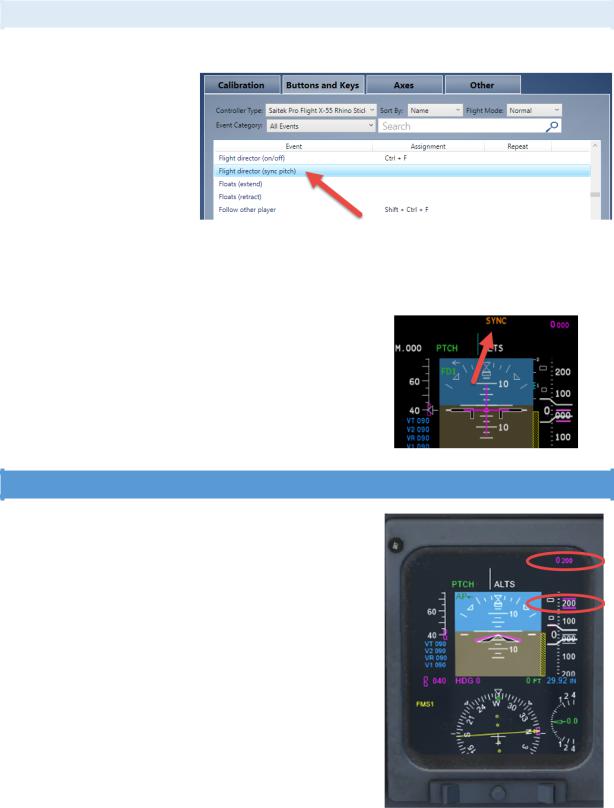
SYNCHRONIZATION
Synchronization enables you to synchronize the flight director bars with the current flight attitude.
The Sync switch on the yoke is not simulated (because it is hidden on the backside of the yoke), so you must use the standard key assignment “flight director synchronization”. Please note this standard key is NOT assigned in FS/P3D so you must
assign a key to it before it can be used. We used [control]-[shift]-[s].
It has no effect in case the autopilot is engaged and only certain lateral and vertical modes allow synchronization:
•Lateral
•Bank mode
•Vertical
•IAS mode
•MACH mode
•VS mode
Synchronization is annunciated by an amber SYNC indication on the
PFD. The message disappears after 3 seconds.
ALTITUDE ALERT SYSTEM
The pilots are notified on the PFD in case they are reaching / leaving a preselected or selected altitude. The respective advisories are all displayed on the PFD but in two different places:
•The readouts and bugs change colours and state according the following rules:
•Approx. 1,000ft before reaching a preselected altitude an aural warning for approx. 1 second is sounded, and the readout and bugs flash in magenta for approx. 4 seconds
•Within 200ft of the (pre-)selected altitude the readout and bugs come steady to indicate altitude capture
•In case the aircraft deviates for more than 200ft from the selected altitude after capture, a 1 second tone will sound and the readout and altitude bugs will start to flash amber (and continue if the deviation occurs or the warning is cancelled by pressing the ALT switch or selecting a different altitude)
•In case the aircraft is 200ft below the selected altitude the flashing magenta bugs and readout will cancel
•If the aircraft deviates further (± 1,000ft) from the selected altitude a 1 second tone sounds
•As soon as the aircraft is again within 200ft of the selected altitude the readout and bugs will cease to flash
Aerosoft – Digital Aviation |
AOM PART 2 |
VOL |
5-1-21 |
CRJ-70 & CRJ-900 |
Systems Description |
5 |
26-Jul-2017 |
|
|
|
|
AUTOPILOT
The installed autopilot is a two-axes, digital, fail-passive autopilot. It commands input to the ailerons, elevators and rudder via the flight control computers, FCCs.
To activate the autopilot the following requirements need to be fulfilled:
•All flight control computers (FCC) are operative
•At least one channel of horizontal trim is available
•At least one yaw damper is engaged
•At least one IRS system is available
•At least one air data computer (ADC) is available
•No significant instability of the aircraft
When flying through turbulent weather autopilot’s corrective signals might reduce passenger comfort. By selecting the turbulence mode, the intensity of signals is reduced to smooth aircraft motion. Turbulence mode is automatically cleared as soon as a localizer is captured. The autopilot is activated with the AP ENG pushbutton and can be deselected by the AP DISC push bar.
The autopilot can also be disengaged by any of the following controls.
1.Push AP/SP DISC switch on control when – this equals the autopilot disengage button / key assignment within FS.
2.Push the AP ENG switch on the flight control panel
3.Lower the AP DISC switch-bar on the right flight control panel
4.Operating the stabilizer trim
5.Pressing the TOGA switch on the thrust levers
6.Disengaging yaw damper by pressing the DISC pushbutton on the yaw damper panel
Disengagement of the autopilot is indicated by an aural warning (cavalry charge) and the AP indications on the PFDs turns red. After two repetitions of the cavalry charge the warning is cancelled automatically.
Automatic disengagement of the autopilot occurs:
•In case both yaw dampers are disengaged or fail
•In case a failure in the FCC monitoring circuit is detected (not simulated)
•In case a stall warning is triggered
•During a windshear and the subsequent clearance procedure.
It automatically disconnects approx. 2 seconds after the windshear warning
In case the autopilot is disengaged automatically, the following warnings (aural and flashing red AP indication on the PFD) may be cancelled by pressing the AP/SP DISC switch or either TOGA switch.
Aerosoft – Digital Aviation |
AOM PART 2 |
VOL |
5-1-22 |
CRJ-70 & CRJ-900 |
Systems Description |
5 |
26-Jul-2017 |
|
|
|
|
COMMUNICATIONS
Some parts of the communication systems cannot be modelled and are not integrated in this package like the crew / passenger addressing system, boarding music system, external communication panels, attendant headsets or similar. So, the communication system basically consists of the
•Audio control panel
•Interphone panel on the centre pedestal
•Intercom control panel
•The radio tuning units
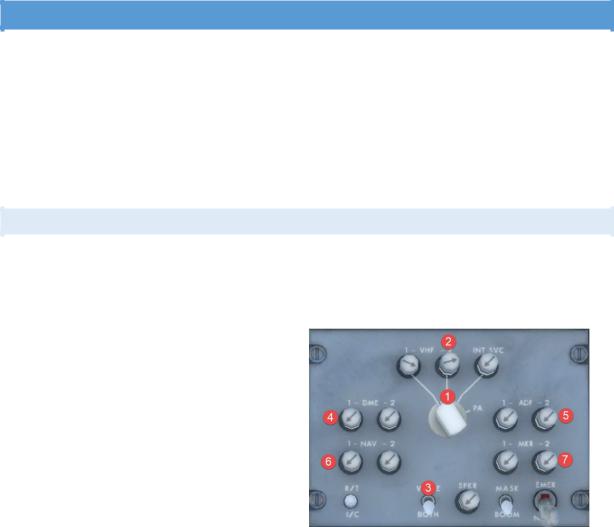
AUDIO CONTROL PANEL
The audio control panel is part of the audio integrating system. The audio integrating system provides display and control for all incoming and outgoing audio signals of the aircraft’s navigation and communication system.
Three audio control panels are the interface between the crew and the audio integrating system.
1.Transmit Selector: Selects the communication system, only one can be active.
2.Receive pushbuttons: Click to select and deselect.
3.Voice/Both: At voice only the voice transmissions are audible, at both voice and station indentification are audible.
4.DME Ident selector: Press to select
5.ADF Ident selector: Press to select
6.NAV Ident selector: Press to select
7.MKR Ident selector: Press to select
The other functions are not simulated.
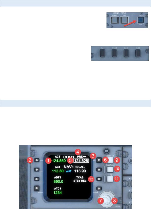
Aerosoft – Digital Aviation |
AOM PART 2 |
VOL |
5-1-23 |
CRJ-70 & CRJ-900 |
Systems Description |
5 |
26-Jul-2017 |
|
|
|
|
INTERPHONE AND INTERCOM CONTROL PANEL
The interphone panel on the centre pedestal is part of the ground crew interphone. The ground crew interphone is used to establish communication between crew inand outside of the aircraft (like during pushback, engine start, aircraft maintenance). Hence there are several
panels in and outside the aircraft to establish communication. The interphone panel on the pedestal is the only one modelled and as the counterparts are missing as outside crew there is no function associated with the ground crew call button which is normally used to establish communication to an outside crew.
The intercom control panel is used for in-airplane- communication and it faces similar limitations like the interphone panel. It is not simulated, on the real plane, it offers four modes of communication:
•PA: Used to address passengers – turns green when activated / pushed
•CHIME: Sounds a chime in the cabin
•CALL: Sounds a chime in the cabin and enables intercom to the flight attendants – turns green when activated / pushed
•EMER: Used for emergency calls from the flight deck to the flight attendants – flashed in amber when activated / pushed
RADIO TUNING UNIT (RTU)
Two VHF (very high frequency) communication systems provide AM (amplitude modulation) voice communication with ground stations and other aircraft. They operate in a range from 118.000 to 136.975 MHz They are tuned by via the radio tuning units in normal operation and in case both RTUs fail a backup tuning unit provides tuning for communication system 1.
The radio tuning units, RTU, are associated with the side they are installed on. Hence the left RTU controls COM 1 and NAV 1 and the right RTU controls COM 2 and NAV 2.
1.FREQUENCY READOUT: The current active frequency is shown in green
2.SELECT KEY: Push once to directly tune the active frequency, push twice to open COM main page
3.TUNING WINDOW: The while box indicates the frequency that can be adjusted
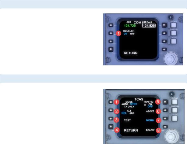
Aerosoft – Digital Aviation |
AOM PART 2 |
VOL |
5-1-24 |
CRJ-70 & CRJ-900 |
Systems Description |
5 |
26-Jul-2017 |
|
|
|
|
4.PRE /RECALL: PRE-indicates the frequency was changed, RECALL indicates the frequency was swapped with the active frequency
5.PRE-SET FREQUENCY: The Preset frequency (shown in white) can be swapped with the active frequency
6.FREQUENCY SWAP: Push to swap active with Preset
7.ADJUST FREQUENCY: in 25 kHz steps (COM) or 50 kHz steps (NAV)
8.ADJUST FREQUENCY: in 1 MHz steps
9.IDENT: Sends ATC Ident
10.DME-H: Locks frequency for DME measuring.
11.1/2: Swaps COM1/NAV1/ADF1 with COM2/NAV2/ADF2
12.TCAS: Push to open TCAS menu
COMS MENU
The COMS menu can be accessed by double clicking the COM select button (see #2 in previous image). It allows the toggling of Squelch.
TCAS MENU
The TCAS menu can be opened with the TCAS select button (see #12).
1.MODE: switch between Auto, Standby and Traffic Advisory Only
2.ALT: Toggles between relative (difference in altitude between aircraft and target) or absolute altitude display
3.TEST: Runs a test program
4.RETURN: back to main RTU menu
5.TRAFFIC: toggles display of traffic symbols on MDF
6.ABOVE: Shows traffic above altitude (can be selected with BELOW)
7.NORM: Standard display
8.BELOW: Shows traffic below altitude (can be selected with ABOVE)
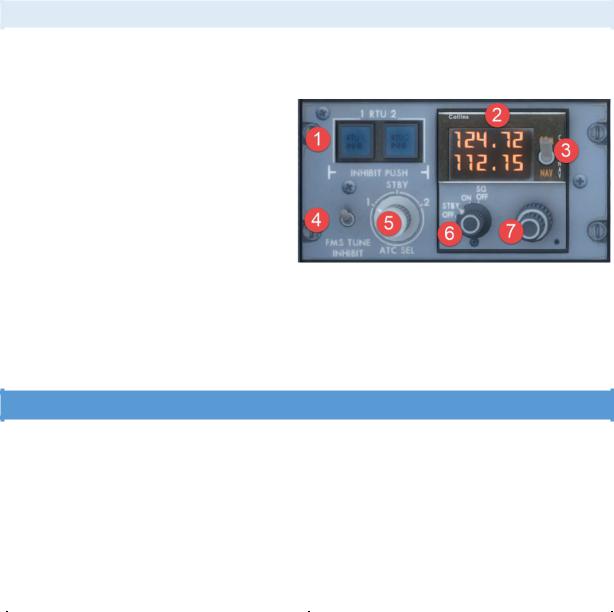
Aerosoft – Digital Aviation |
AOM PART 2 |
VOL |
5-1-25 |
CRJ-70 & CRJ-900 |
Systems Description |
5 |
26-Jul-2017 |
|
|
|
|
BACKUP TUNING UNIT
The backup tuning unit provides a spare / backup in case both RTUs fail. Normally the backup tuning unit stays in standby mode the entire flight. As soon as it is switched on it takes control of COM1 and NAV 1.
1.RTU INHIBIT: Disables either RTU
2.FREQUENCY DISPLAY: Shows COM1 (upper) and NAV1) lower, TX is displayed to indicate transmission
3.TUNING SELECTOR: Toggles between tuning COM1 and NAV1
4.FMS TUNE INHIBIT: Stops FMS Autotune function
5.ATC SEL: To select the active transponder
6.MODE SELECTOR:
a.OFF: Display off
b.STB: Displays the frequency shown in RTU1
c.ON: Frequency is controlled by the tuning knob
d.SQ OFF: Squelch selected off
7.TUNING KNOB: To set frequency
ELECTRICAL
The CRJ’s electrical system can be split into an alternating current, AC, subsystem and a direct current, DC, subsystem. The alternating current, AC system is supplied with power from the engine generators (integrated drive generators, IDGs), the auxiliary power unit’s generator or the air driven generator, ADG (which is a backup in case both IDGs fail). The direct current, DC, system is supplied with power from two transformer rectifier units, TRUs, the main battery, or the APU battery. The TRUs convert alternating current to direct current. To reload both batteries, battery chargers are installed as well.
Both subsystems use computers to ensure the proper power distribution to the respective systems. The following table shows the available AC and DC busses.
AC busses |
DC busses |
||
• |
AC BUS 1 |
• |
DC BUS 1 |
• |
AC BUS 2 |
• |
DC BUS 2 |
• |
AC ESSENTIAL BUS |
• |
DC ESSENTIAL BUS |
• |
AC SERVICE BUS |
• |
DC SERVICE BUS |
• |
ADG BUS |
• |
DC BATTERY BUS |
|
|
• |
DC EMERGENCY BUS |
|
|
• |
DC UTILITY BUS |
|
|
• MAIN BATTERY DIRECT BUS |
|
|
|
• APU BATTERY DIRECT BUS |
|
Furthermore – when on ground – an external power receptacle is available which allows the CRJ to be supplied with ground power. The electrical power panel on the overhead panel is used to control the electrical systems. Error messages, warning or advisories are indicated on the EICAS.
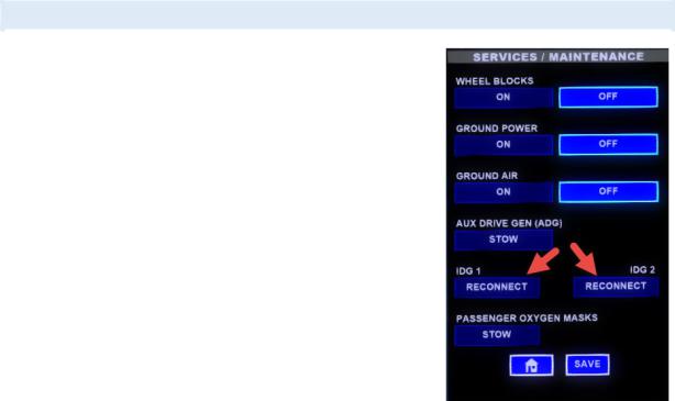
Aerosoft – Digital Aviation |
AOM PART 2 |
VOL |
5-1-26 |
CRJ-70 & CRJ-900 |
Systems Description |
5 |
26-Jul-2017 |
|
|
|
|
ALTERNATING CURRENT, AC SYSTEM
During normal operation, the IDGs supply alternating current. The APU may be used as a backup in case both IDGs fail. In case even the APU fails, the CRJ is equipped with an Air Driven Generator, ADG, which is basically a propeller which is extended into the airstream. The ADG can provide enough power for the most important aircraft systems to be still able to fly the aircraft.
The IDGs are monitored regarding temperatures, oil pressure and supplied power. In case of exceedances the affected IDG can be disconnected automatically. Nevertheless, there is also a possibility by means of a switch light on the electrical power panel, to disconnect the IDG manually.
Please bear in mind that a disconnected IDG (no matter if disconnected automatically or manually) can only be reconnected on ground. Please open Dave, go to the “Services / Maintenance” page to reconnect the IDG. Disconnected IDGs are displayed in blue. Press on “Reconnect” and “Save” to reconnect.
Before disconnecting you may try to reset the IDG by switching the generator switch on the electrical control panel to OFF/RESET and then back to ON.
Aerosoft – Digital Aviation |
AOM PART 2 |
VOL |
5-1-27 |
CRJ-70 & CRJ-900 |
Systems Description |
5 |
26-Jul-2017 |
|
|
|
|
The following table shows the power distribution in the AC system for normal operation:
|
AC BUS 1 |
|
AC BUS 2 |
|
AC ESSENTIAL |
|
|
|
|
|
|
• |
Flight Recorder Power |
• |
TRU 2 |
• |
Essential TRU 1 |
• |
TRU 1 |
• |
Essential TRU 2 |
• Display Cooling Fan 1 |
|
• |
Main Battery Charger |
• |
Recirculating Fan 2 |
• Avionics Cooling Fan 1 |
|
• |
Recirculating Fan 1 |
• |
Galley Exhaust Fan |
• |
Crossflow Pump |
• |
Display Cooling Fan 2 |
• |
Galley Heater |
• |
Left Pitot Heater |
• |
Lavatory Exhaust Fan |
• |
Slats and Flaps |
• |
Standby Pitot Heater |
• |
Baggage Compartment |
|
Channel 2 |
• |
Left AOA Heater |
• |
Heater |
• Pitch Trim Channel 2 |
• |
Ice Detector 1 |
|
• |
Slats and Flaps |
• |
Hydraulic Pumps 3A |
• |
Left Window Heater |
|
Channel 1 |
|
and 1B |
• |
Cabin Ceiling Lighting |
• |
Pitch Trim Channel 1 |
• |
Right Windshield |
• CB Panel Integral Lights |
|
• |
Hydraulic Pumps 3B |
|
Heaters |
• Pilot Panel Integral Lights |
|
|
and 2B |
• |
Right Window Heater |
• |
Overhead Panel Integral |
• |
Hydraulic System Fan |
• |
Ice Detector 2 |
• |
Lights |
• |
Left Windshield Heater |
• |
Co-pilot Panel Integral |
• Centre Panel Integral Lights |
|
• |
TAT Probe Heater |
|
Lights |
• Traffic Alert and Collision |
|
• |
Right AOA Heater |
• |
Inertial Reference Unit |
• |
Avoidance System (TCAS) |
• |
Right Pitot Heater |
|
Fan |
• |
Engine Ignition A |
• |
Enhanced Ground |
|
|
|
|
|
Proximity |
|
|
|
|
• |
Warning System |
|
|
|
|
|
(EGPWS) |
|
|
|
|
• |
Engine Vibration |
|
|
|
|
|
Monitor |
|
|
|
|
• Avionics Cooling Fan 2 |
|
|
|
|
|
• |
ADG Heater |
|
|
|
|
|
AC SERVICE BUS |
|
ADG BUS |
|
|
|
|
• |
APU Charger |
• |
Hydraulic Pump 3B |
• |
Logo Lights |
• |
Pitch Trim 2 |
• |
Cabin Sidewall Lighting |
• Slats and Flaps #1 |
|
• |
Cabin Ceiling Lighting |
• Slats and Flaps #2 |
|
• |
Toilet |
|
|
• |
Water System |
|
|
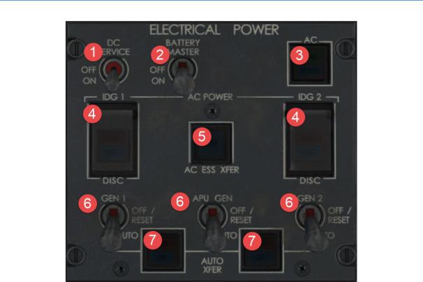
Aerosoft – Digital Aviation |
AOM PART 2 |
VOL |
5-1-28 |
CRJ-70 & CRJ-900 |
Systems Description |
5 |
26-Jul-2017 |
|
|
|
|
CONTROLS ON OVERHEAD PANEL
1.DC SERVICE: Connects the DC service bus to the APU battery direct bus
2.BATTER MASTER: Used to supply the battery bus with power from the APU or main direct busses. Always ON in flight!
3.AC: External Power toggle
-AVAIL indicates connected source
-IN USE indicates AC busses are connected to external power unit
4.IDG1/2 DISCONNECT: Open guard and press push button to disconnect IDG1 (reconnect on ground only!)
-DISC (white) indicates IDG is disconnected
-FAULT (amber) indicates low oil pressure or high temperature
5.AC ESS XFER: Switches essential bus feed from AC bus 1 to AC bus 2, switches automatic in case of IDG1 failure
-ALTN (white) indicates essential bus is fed from AC bus 2
6.GEN 1: Used to switch generators between AUTO and OFF
7.AUTO XFER: Disables automatic transfer of respective IDG
-OFF indicates autotransfer is deactivated
-FAIL indicates a fault is preventing autotransfer
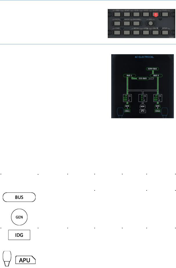
Aerosoft – Digital Aviation |
AOM PART 2 |
VOL |
5-1-29 |
CRJ-70 & CRJ-900 |
Systems Description |
5 |
26-Jul-2017 |
|
|
|
|
EICAS SYNOPTIC PAGE – HOW TO OPEN AC & DC ELECTRICAL SYNOPTIC PAGES
The AC and DC electrical synoptic page is opened via the EICAS control panel by pressing the ELEC key (1) once to open the AC electrical synoptic page and twice to open the DC electrical synoptic page.
EICAS SYNOPTIC PAGE – ELECTRICAL POWER SUPPLIED FROM ENGINES
On the EICAS Electrical displays the green flow lines show energized busses, white lines show not energized busses.
EICAS DIGITAL |
GREEN |
AMBER |
WHITE |
HALF INTENSITY AMBER |
AMBER |
READOUT |
|
|
|
|
DASHES |
XXX kVA |
Generator |
Generator |
Generator not |
Insufficient data |
Invalid data |
|
loaded |
overload |
loaded |
|
|
XXX V |
Voltage in |
- |
Voltage not in |
Insufficient data |
Invalid data |
|
range |
|
range |
|
|
XXX HZ |
Frequency |
- |
Frequency not |
Insufficient data |
Invalid data |
|
in range |
|
in range |
|
|
EICAS OUTLINE |
GREEN |
AMBER |
WHITE |
HALF |
HALF |
|
|
|
|
INTENSITY |
INTENSITY |
|
|
|
|
AMBER |
CYAN |
|
Bus powered |
Bus not |
- |
Invalid data |
- |
|
|
powered or |
|
|
|
|
|
voltage low |
|
|
|
|
Generator on |
Generator off |
Both |
Invalid data |
- |
|
|
with engine / |
generator and |
|
|
|
|
APU running |
engine / APU |
|
|
|
|
|
are off |
|
|
|
Constant speed |
Low oil |
Engine is off or |
Invalid data |
- |
|
drive on |
pressure or |
IDG is |
|
|
|
|
high oil |
disconnected |
|
|
|
|
temperature |
|
|
|
|
- |
- |
Engine / APU |
Invalid data |
Engine / APU |
|
|
|
off |
|
running and |
|
|
|
|
|
ready to load |
|
|
|
|
|
|
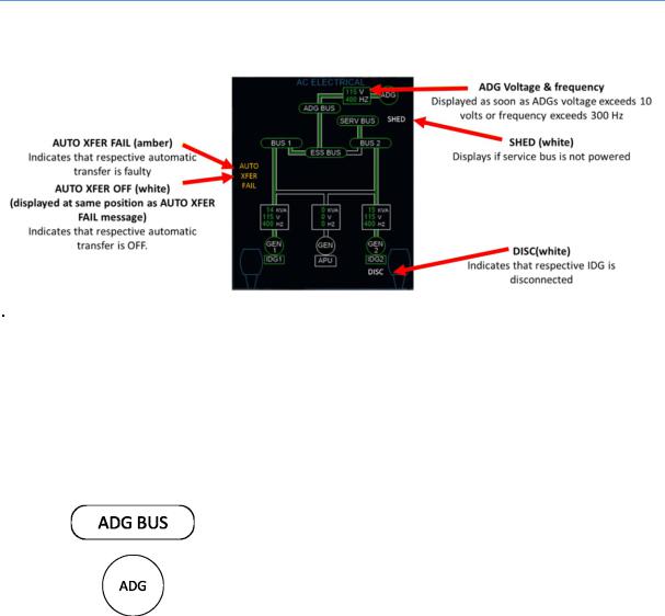
Aerosoft – Digital Aviation |
AOM PART 2 |
VOL |
5-1-30 |
CRJ-70 & CRJ-900 |
Systems Description |
5 |
26-Jul-2017 |
|
|
|
|
EICAS SYNOPTIC PAGE – ELECTRICAL POWER SUPPLIED FROM AIR DRIVEN GENERATOR
EICAS DIGITAL READOUT |
GREEN |
WHITE |
AMBER DASHES |
XXX V |
Between 108 and 130 |
Less than 108 or more |
Invalid data |
|
volts |
than 130 volts |
|
XXX HZ |
Between 360 and 440 Hz |
Less than 360 or more |
Invalid data |
|
|
than 440 Hz |
|
EICAS OUTLINE |
GREEN |
WHITE |
|
ADG outline green |
ADG outline white |
|
|
|
|
Voltage and frequency digital |
Voltage or frequency digital |
|
readouts green |
readouts white |
|
|
|
 Loading...