


 Loading...
Power Energy Logger
Model PEL 102 & PEL 103
User Manual
ENGLISH


 ®
®
www.aemc.com |
|
|
|
CHAUVIN ARNOUX GROUP |
|
||
|
|||
Copyright © Chauvin Arnoux®, Inc. d.b.a. AEMC® Instruments. All rights reserved.
No part of this documentation may be reproduced in any form or by any means (including electronic storage and retrieval or translation into any other language) without prior agreement and written consent from Chauvin Arnoux®, Inc., as governed by United States and International copyright laws.
Chauvin Arnoux®, Inc. d.b.a. AEMC® Instruments
15 Faraday Drive • Dover, NH 03820 USA
Tel: (800) 945-2362 or (603) 749-6434 • Fax: (603) 742-2346
This documentation is provided “as is,” without warranty of any kind, express, implied, or otherwise. Chauvin Arnoux®, Inc. has made every reasonable effort to ensure that this documentation is accurate; but does not warrant the accuracy or completeness of the text, graphics, or other information contained in this documentation. Chauvin Arnoux®, Inc. shall not be liable for any damages, special, indirect, incidental, or inconsequential; including (but not limited to) physical, emotional or monetary damages due to lost revenues or lost profits that may result from the use of this documentation, whether or not the user of the documentation has been advised of the possibility of such damages.
Chauvin Arnoux®, Inc, AEMC®, DataView®, AmpFlex®, MiniFlex® and PowerPad® are registered trademarks of AEMC® Instruments.

Thank you for purchasing a Power Energy Logger Model PEL 102 or PEL 103
For best results from your instrument and for your safety, read the enclosed operating instructions carefully and comply with the precautions for use. These products must be only used by qualified and trained users.
WARNING, risk of DANGER! The operator must refer to these instructions whenever this danger symbol appears.
CAUTION! Risk of electric shock. The voltage at the parts marked with this symbol may be dangerous.
Equipment is protected by double insulation.
USB socket.
SD Card.
Important instructions to read and to fully understand.
Ethernet socket (RJ45).
Main power supply input.
Ground/Earth.
Useful information or hint to read.
Magnetic fields can damage hard drives and medical devices.
Must not be applied to or removed from bare conductors carrying dangerous voltages.
Type B current sensor as per EN 61010-2-032.
The product has been declared recyclable after analysis of its life cycle in accordance with the ISO14040 standard.
The CE marking guarantees conformity with European directives and with regulations covering EMC.
The trash can with a line through it means that in the European Union, the product must undergo selective disposal for the recycling of electric and electronic material, in compliance with Directive WEEE 2002/96/EC.
Definition of Measurement Categories (CAT)
■■ |
CAT IV |
Measurement category IV corresponds to measurements taken at the source of low-voltage installations. |
|
|
Example: power feeders, counters and protection devices. |
■■ |
CAT III |
Measurement category III corresponds to measurements on building installations. |
|
|
Example: distribution panel, circuit-breakers, machines or fixed industrial devices. |
■■ |
CAT II |
Measurement category II corresponds to measurements taken on circuits directly connected to low-voltage installations. |
|
|
Example: power supply to domestic electrical appliances and portable tools. |
Precautions for Use
This instrument complies with safety standard IEC 61010-2-030, the leads comply with IEC 61010-031 for voltages of 1000V in measurement category III or 600V in measurement category IV and the current sensors comply with IEC 61010-2-032. Failure to observe
the safety instructions may result in electric shock, fire, explosion, and destruction of the instrument and of the installations.
■■ The operator and/or the responsible authority must carefully read and clearly understand the various precautions to be taken in use. Sound knowledge and a keen awareness of electrical hazards are essential when using this instrument.
■■ For your safety, use only the compatible leads and accessories delivered with the instrument, which comply with IEC standard 61010-031 (2002). When sensors or accessories having a lower voltage rating and/or category are connected to the instrument, the lower voltage and/or category applies to the system so constituted.
■■ Before each use, check that the leads, enclosures, and accessories are in perfect condition. Any lead, sensor or accessory on which the insulation is damaged (even partially) must be repaired or scrapped.
■■ Do not use the instrument on networks for which the voltage or category exceeds those mentioned. ■■ Do not use the instrument if it seems to be damaged, incomplete, or poorly closed.
■■ Use only the AC power adapter and battery pack supplied by the manufacturer, which include specific safety features.
■■ When removing and replacing the battery and/or the SD-Card, make sure that the device is disconnected and switched off.
■■ We recommend using Personal Protection Equipment where required. ■■ Keep your hands away from unused terminals.
■■ If the instrument is wet, dry it before connecting it.
■■ All troubleshooting and metrological checks must be performed by authorized (competent and accredited) personnel, with the instrument completely disconnected.

|
|
Table of Contents |
|
1. INTRODUCTION............................................................................................................... |
6 |
||
1.1 |
Receiving Your Shipment......................................................................................................................................... |
6 |
|
1.2 |
Ordering Information................................................................................................................................................ |
6 |
|
|
1.2.1 |
Accessories.................................................................................................................................................. |
7 |
|
1.2.2 |
Replacement Parts....................................................................................................................................... |
7 |
2. PRODUCT FEATURES...................................................................................................... |
8 |
||
2.1 |
Description............................................................................................................................................................... |
8 |
|
2.2 |
Front Panel Features................................................................................................................................................ |
9 |
|
2.3 |
Back Panel Features.............................................................................................................................................. |
10 |
|
2.4 |
Lead Inputs............................................................................................................................................................ |
10 |
|
2.5 Installation of the Color-coded ID Markers............................................................................................................ |
11 |
||
2.6 |
Connection Features.............................................................................................................................................. |
11 |
|
2.7 |
Mounting and Location.......................................................................................................................................... |
12 |
|
2.8 |
Button Functions................................................................................................................................................... |
12 |
|
2.9 LCD Display (PEL 103).......................................................................................................................................... |
12 |
||
2.10 |
LED Status........................................................................................................................................................... |
13 |
|
2.11 |
Memory Capacity................................................................................................................................................. |
15 |
|
3. OPERATION................................................................................................................... |
16 |
||
3.1 |
Charging the Battery.............................................................................................................................................. |
16 |
|
3.2 |
Operating the PEL.................................................................................................................................................. |
16 |
|
3.3 Turning the Instrument ON/OFF |
|
||
|
|
............................................................................................................................. |
17 |
|
3.3.1 Turning the PEL ON.................................................................................................................................... |
17 |
|
|
3.3.2 Turning the PEL OFF.................................................................................................................................. |
17 |
|
3.4 Starting/Stopping a Recording and Enabling Bluetooth........................................................................................ |
18 |
||
3.5 |
Connections........................................................................................................................................................... |
18 |
|
|
3.5.1 |
Power Supply............................................................................................................................................. |
18 |
|
3.5.2 Standby Mode (and Display Brightness).................................................................................................... |
19 |
|
|
3.5.3 |
Memory Card (SD-Card)............................................................................................................................. |
19 |
|
3.5.4 USB Connection to the PEL....................................................................................................................... |
19 |
|
|
3.5.5 LAN Ethernet Connection to the PEL......................................................................................................... |
19 |
|
|
3.5.6 Bluetooth Connection to the PEL............................................................................................................... |
20 |
|
|
3.5.6.1 Pairing using Windows 7.................................................................................................................... |
20 |
|
3.6 Distribution Systems and PEL Hook-ups.............................................................................................................. |
22 |
||
|
3.6.1 |
Single Phase 2-Wire ................................................................................................................................ |
22 |
|
3.6.2 |
Single Phase 3-Wire (Split Phase from a center tap transformer)............................................................. |
22 |
|
3.6.3 3-Phase 3-Wire Power Networks .............................................................................................................. |
23 |
|
|
3.6.3.1 3-Phase 3-Wire ∆ (with 2 current sensors)......................................................................................... |
23 |
|
|
3.6.3.2 3-Phase 3-Wire ∆ (with 3 current sensors)......................................................................................... |
23 |
|
|
3.6.3.3 3-Phase 3-Wire Open ∆ (with 2 current sensors)............................................................................... |
24 |
|
|
3.6.3.4 3-Phase 3-Wire Open ∆ (with 3 current sensors]............................................................................... |
24 |
|
|
3.6.3.5 3-Phase 3-Wire Y (with 2 current sensors)......................................................................................... |
25 |
|
2 |
Power & Energy Logger Model PEL 102 and PEL 103 |
|
3.6.3.6 3-Phase 3-Wire Y (with 3 current sensors]......................................................................................... |
25 |
||
|
3.6.3.7 3-Phase 3-Wire ∆ Balanced (with 1 current sensor)........................................................................... |
26 |
||
|
3.6.4 3-Phase 4-Wire Y Power Networks............................................................................................................ |
26 |
||
|
3.6.4.1 3-Phase 4-Wire Y (with 3 current sensors)......................................................................................... |
26 |
||
|
3.6.4.2 3-Phase 4-Wire Y Balanced............................................................................................................... |
27 |
||
|
3.6.4.3 3-Phase 4-Wire Y 2½ Element........................................................................................................... |
27 |
||
|
3.6.5 |
3-Phase 4-Wire ∆........................................................................................................................................ |
28 |
|
|
3.6.5.1 |
3-Phase 4-Wire ∆................................................................................................................................ |
28 |
|
|
3.6.5.2 3-Phase 4-Wire Open ∆...................................................................................................................... |
28 |
||
|
3.6.6 |
DC Power Networks................................................................................................................................... |
29 |
|
|
3.6.6.1 |
DC 2-Wire........................................................................................................................................... |
29 |
|
|
3.6.6.2 |
DC 3-Wire........................................................................................................................................... |
29 |
|
|
3.6.6.3 |
DC 4-Wire........................................................................................................................................... |
30 |
|
3.7 LCD Display Modes (PEL 103 Only)...................................................................................................................... |
31 |
|||
|
3.7.1 |
Base Measurements - Displayed Valuess................................................................................................. |
31 |
|
|
3.7.2 |
Energy - Displayed Values....................................................................................................................................... |
34 |
|
|
3.7.3 |
Harmonic Display Values.......................................................................................................................................... |
37 |
|
|
3.7.4 |
Max Display Values................................................................................................................................................... |
38 |
|
|
3.7.5 |
Information Display Values....................................................................................................................................... |
39 |
|
|
3.7.6 |
Configuratios (PEL 103).............................................................................................................................. |
40 |
|
4. PEL CONTROL PANEL - DATAVIEW® SOFTWARE........................................................... |
42 |
|||
4.1 |
Installing DataView................................................................................................................................................. |
42 |
||
4.2 Connecting to a PEL.............................................................................................................................................. |
48 |
|||
|
4.2.1 Add an Instrument Wizard.......................................................................................................................... |
49 |
||
|
4.2.2 |
USB Connection......................................................................................................................................... |
50 |
|
|
4.2.3 |
Ethernet Network Connection.................................................................................................................... |
52 |
|
|
4.2.4 |
Bluetooth Connection................................................................................................................................. |
53 |
|
4.3 |
PEL Control Panel.................................................................................................................................................. |
54 |
||
|
4.3.1 Opening and Using the Control Panel........................................................................................................ |
54 |
||
|
4.3.2 Modifying a Connection Type..................................................................................................................... |
57 |
||
|
4.3.3 Reconnecting and Disconnecting an Instrument....................................................................................... |
57 |
||
|
4.3.4 Removing an Instrument from the PEL Network........................................................................................ |
57 |
||
4.4 |
Configuring the PEL............................................................................................................................................... |
58 |
||
|
4.4.1 |
General Options.......................................................................................................................................... |
59 |
|
|
4.4.2 |
Communication Options............................................................................................................................. |
60 |
|
|
4.4.3 |
Measurement Tab Options......................................................................................................................... |
62 |
|
|
4.4.4 Current Sensors and Ratios....................................................................................................................... |
63 |
||
|
4.4.5 |
Recording Tab Options............................................................................................................................... |
65 |
|
|
4.4.6 |
Meters Tab Options.................................................................................................................................... |
67 |
|
|
4.4.7 Configuring and Recording Data Example................................................................................................. |
68 |
||
|
4.4.8 Modifying an Instrument’s Configuration.................................................................................................... |
69 |
||
4.5 |
Downloading Recorded Data................................................................................................................................. |
69 |
||
4.6 Using the Download Folder................................................................................................................................... |
71 |
|||
4.7 |
PEL Reports........................................................................................................................................................... |
72 |
||
Power & Energy Logger Model PEL 102 and PEL 103 |
3 |
|
4.7.1 Specifying the Default Report Template..................................................................................................... |
72 |
||
4.8 Power & Energy Logger (PEL) Android App........................................................................................................... |
72 |
|||
5. SPECIFICATIONS.......................................................................................................... |
74 |
|||
5.1 |
Reference Conditions............................................................................................................................................ |
74 |
||
5.2 |
Electrical Specifications......................................................................................................................................... |
74 |
||
|
5.2.1 |
Voltage Inputs............................................................................................................................................. |
74 |
|
|
5.2.2 |
Current Inputs............................................................................................................................................. |
74 |
|
|
5.2.3 Accuracy Specifications (excluding current sensors)................................................................................. |
75 |
||
|
5.2.3.1 |
Specifications at 50/60Hz .................................................................................................................. |
75 |
|
|
5.2.3.2 |
Specifications @ 400Hz...................................................................................................................... |
77 |
|
|
5.2.3.3 |
Specifications @ DC........................................................................................................................... |
77 |
|
|
5.2.3.4 |
Temperature........................................................................................................................................ |
78 |
|
|
5.2.3.5 |
Common Mode Rejection................................................................................................................... |
78 |
|
|
5.2.3.6 |
Magnetic Field Influence..................................................................................................................... |
78 |
|
|
5.2.4 |
Current Sensors.......................................................................................................................................... |
78 |
|
|
5.2.4.1 |
Precautions for Use............................................................................................................................ |
78 |
|
|
5.2.4.2 |
Use and Characteristics..................................................................................................................... |
78 |
|
|
5.2.4.3 |
MiniFlex® MA193................................................................................................................................ |
79 |
|
|
5.2.4.4 |
Other Current Sensors........................................................................................................................ |
79 |
|
|
5.2.4.5 |
Accuracy............................................................................................................................................. |
81 |
|
5.3 |
Bluetooth............................................................................................................................................................... |
|
83 |
|
5.4 |
Power Supply......................................................................................................................................................... |
83 |
||
5.5 |
Mechanical Specifications..................................................................................................................................... |
84 |
||
5.6 |
Environmental Specifications................................................................................................................................. |
84 |
||
5.7 |
Safety Specifications............................................................................................................................................. |
84 |
||
5.8 |
Electromagnetic Compatibility............................................................................................................................... |
84 |
||
6. MAINTENANCE.............................................................................................................. |
85 |
|||
6.1 |
Battery................................................................................................................................................................... |
|
85 |
|
6.2 |
Battery Indicator.................................................................................................................................................... |
85 |
||
6.3 |
Cleaning................................................................................................................................................................. |
|
85 |
|
6.4 Updating the Internal Software ............................................................................................................................. |
86 |
|||
APPENDIX A...................................................................................................................... |
|
87 |
||
A.1 |
Measurements....................................................................................................................................................... |
87 |
||
|
A.1.1 |
Definition.................................................................................................................................................... |
87 |
|
|
A.1.2 |
Sampling.................................................................................................................................................... |
87 |
|
|
A.1.2.1 |
Sampling Period................................................................................................................................. |
87 |
|
|
A.1.2.2 Locking of Sampling Frequency......................................................................................................... |
88 |
||
|
A.1.2.3 |
AC/DC................................................................................................................................................ |
88 |
|
|
A.1.2.4 Measurement of Neutral Current........................................................................................................ |
88 |
||
|
A.1.2.5 |
“1 second” Quantities........................................................................................................................ |
88 |
|
|
A.1.2.6 |
Aggregation........................................................................................................................................ |
88 |
|
|
A.1.2.7 |
Max..................................................................................................................................................... |
88 |
|
|
A.1.2.8 |
Energy Calculations............................................................................................................................ |
89 |
|
4 |
Power & Energy Logger Model PEL 102 and PEL 103 |
A.2 |
Measurement Formulas......................................................................................................................................... |
89 |
|
A.3 |
Aggregation........................................................................................................................................................... |
90 |
|
A.4 |
Supported Electrical Networks.............................................................................................................................. |
92 |
|
A.5 |
Phase Order........................................................................................................................................................... |
94 |
|
|
A.5.1 |
Current Phase Order.................................................................................................................................. |
94 |
|
A.5.2 |
Voltage Phase Order.................................................................................................................................. |
95 |
|
A.5.3 Current vs Voltage Phase Order................................................................................................................. |
96 |
|
A.6 |
Quantities According to the Supply Systems........................................................................................................ |
97 |
|
A.7 |
Glossary of Terms.................................................................................................................................................. |
99 |
|
Repair and Calibration.................................................................................................... |
102 |
||
Technical and Sales Assistance...................................................................................... |
102 |
||
Limited Warranty............................................................................................................. |
103 |
||
Warranty Repairs............................................................................................................. |
103 |
||
Power & Energy Logger Model PEL 102 and PEL 103 |
5 |

1. INTRODUCTION
1.1 Receiving Your Shipment
Upon receiving your shipment, make sure that the contents are consistent with the packing list. Notify your distributor of any missing items. If the equipment appears to be damaged, file a claim immediately with the carrier and notify your distributor at once, giving a detailed description of any damage. Save the damaged packing container to substantiate your claim.
1.2 Ordering Information
Power & Energy Logger Model PEL 102 |
(no LCD, w/3 MA193-10-BK sensors)............................................. |
Cat. #2137.51 |
Power & Energy Logger Model PEL 103 |
(with LCD, w/3 MA193-10-BK sensors).......................................... |
Cat. #2137.52 |
Power & Energy Logger Model PEL 102 |
(no LCD, no sensors)....................................................................... |
Cat. #2137.61 |
Power & Energy Logger Model PEL 103 |
(with LCD, no sensors).................................................................... |
Cat. #2137.62 |
Shipping Contents:
OR
(4) Black Test Leads and Alligator Clips
Cat. #2137.76
(1) of the following:
Power Energy Logger Model PEL 102
Power Energy Logger Model PEL 103
Cat. #2137.51 or Cat. #2137.52
(12) Color-coded ID Markers
Cat. #2140.45
(1) Small Classic Tool Bag |
(1) Power Cord, 5 ft 115V |
|
Cat. #5000.14 |
||
Cat. #2133.72 |
||
|
Also Included:
(1) Safety Sheet for the PEL
(1) Safety Sheet for the MiniFlex® Sensors
(1) Compliance Sheet
(1) 2 GB SD-Card
(1) Quick Start User Guide
(1) 4 GB USB Stick with User Manual & DataView® Software
(1) Battery (NiMH AAA 8.4V) - Cat.#2137.81
(3) MiniFlex® MA193-10-BK
Cat. #2140.48
(included only with the purchase of
Cat. #2137.51 or Cat. #2137.52)
(1) USB SD-Card Adapter
Cat. #5000.45
(1) 5 ft USB Cable
Cat. #2140.46
6 |
Power & Energy Logger Model PEL 102 and PEL 103 |

1.2.1 Accessories
USB cable, A/B 10 ft (3m)................................................................................................................................. |
Cat. #2136.80 |
PEL Power Adapter........................................................................................................................................... |
Cat. #2137.77 |
AC/DC Current Probe Model J93..................................................................................................................... |
Cat. #2140.49 |
AC/DC Current Probe Model MR193-BK......................................................................................................... |
Cat. #2140.28 |
AC Current Probe Model MN93-BK.................................................................................................................. |
Cat. #2140.32 |
AC Current Probe Model SR193-BK................................................................................................................. |
Cat. #2140.33 |
AmpFlex® Sensor 24" Model 193-24-BK (black connector) ............................................................................ |
Cat. #2140.34 |
AmpFlex® Sensor 36" Model 193-36-BK (black connector) ............................................................................ |
Cat. #2140.35 |
AC Current Probe Model MN193-BK (black connector) ................................................................................. |
Cat. #2140.36 |
MiniFlex® Current Sensor 10" Model MA193-10-BK (black connector)........................................................... |
Cat. #2140.48 |
MiniFlex® Current Sensor 14" Model MA193-14-BK (black connector)........................................................... |
Cat. #2140.50 |
AC/DC Current Probe Model SL261*................................................................................................................ |
Cat. #1201.51 |
*BNC Adapter for Current Probe Model SL261.......................................................................................... |
Cat. #2140.40 |
1.2.2 Replacement Parts
Small Classic Tool Bag...................................................................................................................................... |
Cat. #2133.72 |
Battery (custom factory replacement NiMH AAA 8.4V) ................................................................................... |
Cat. #2137.81 |
Lead, Set of 4, 10 ft 4mm Straight Banana Plugs with Set of Alligator Clips (Black) UL |
|
and a Set of 12 Color-coded Input ID Markers................................................................................................. |
Cat. #2137.76 |
Set of 12 Color-coded Input ID Markers........................................................................................................... |
Cat. #2140.45 |
USB Cable A/B, 5 ft (1.5m)............................................................................................................................... |
Cat. #2140.46 |
Power Cord, 5 ft (1.5m) 115V............................................................................................................................ |
Cat. #5000.14 |
USB SD-card Adapter....................................................................................................................................... |
Cat. #5000.45 |
DataView® Software Updates are Available at www.aemc.com
PEL Android App Available on the Google Play Store at https://play.google.com/store/apps/details?id=com.aemc.pel&hl=en
Power & Energy Logger Model PEL 102 and PEL 103 |
7 |

2. PRODUCT FEATURES
2.1 Description
PEL: Power and Energy Logger
The PEL 102 and PEL 103 are simple-to-use, single, dual (split-phase) and three phase (Y, ∆) power and energy loggers.
The PEL offers all the necessary functions for Power/Energy data logging for most of the 50Hz, 60Hz, and 400Hz and DC distribution systems worldwide offering numerous distribution set-ups. The PEL is designed to work in 1000V CAT III and 600V CAT IV environments.
The PEL is compact in size and fits in many distribution panels.
The PEL provides the following measurements (or calculations):
■■ Direct voltage measurements up to 1000V CAT III and 600V CAT IV
■■ AC current measurements from 200mA up to 10,000A with MA193 external current sensors
■■ Power measurements: VA, W and var
■■ Energy measurements: VAh, Wh (source, load) and varh (4 quadrants)
■■ Power Factor (PF), Cos ϕ, and Tan Φ ■■ Crest Factor
■■ Total Harmonic Distortion (THD) for voltages and currents
■■ Harmonics from the fundamental signal up to the 50th order for 50/60Hz voltages and currents
■■ Frequency measurements
■■ RMS and DC measurements @ 128 samples/cycle – each phase simultaneously ■■ Bright triple LCD on the Model PEL 103 (3 phases shown simultaneously)
■■ Storage of measured and calculated values on a SD-Card or SDHC-Card
■■ Automatic recognition of the different types of current sensors
■■ Configuration of current and voltage ratios with external sensors
■■ 17 types of supported hook-ups or electrical distribution systems
■■ USB, LAN, and Bluetooth communication
■■ DataView® Software for data download, viewing of measurements, real-time communication with a PC and report generation with predefined or custom templates
8 |
Power & Energy Logger Model PEL 102 and PEL 103 |
2.2 Front Panel Features
|
|
|
|
|
|
|
1 |
|
|
|
|
|
|
|
2 |
V1 V2 V3 N |
I1 |
I2 |
I3 |
V1 V2 V3 N |
I1 |
I2 |
I3 |
1000V CAT III |
600V CAT IV |
|
|
1000V CAT III |
600V CAT IV |
|
|
|
MODEL PEL 102 |
|
|
MODEL PEL 103 |
3 |
||
4
A  B
B
5
POWER & ENERGY LOGGER |
POWER & ENERGY LOGGER |
||
ON/OFF |
|
ON/OFF |
|
START/STOP |
|
START/STOP |
6 |
C |
D |
C |
D |
7 |
8 |
Figure 1
1Four voltage input terminals.
2Three current input terminals.
3Rigid molded casing over-molded with thermo-adhesive rubber.
4Digital LCD displaying measured, calculated and parameterizing quantities (see § 2.9).
5Two (PEL 102) or Four (PEL 103) function buttons (see § 2.8).
A Enter Button B Navigation Button C Control button D On/Off button
6Nine LEDs for status information (see § 2.10).
7Connections for USB, Ethernet, SD memory card and terminal cover caps.
8Standard (IEC C7 figure 8 terminal – non polarized) power connector for 110/250VAC power source.
Power & Energy Logger Model PEL 102 and PEL 103 |
9 |
2.3 Back Panel Features
1
2
WARNING!
Disconnect all inputs before opening the battery compartment
Only replace with 8.4V
NiMH custom battery pack
Power Supply:
110-250V DC/AC 50/60Hz 30VA
MADE IN FRANCE
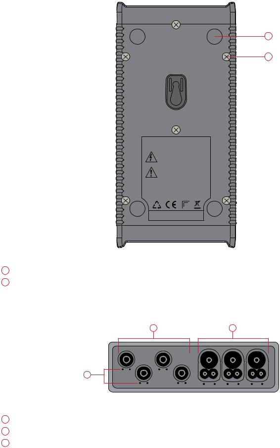
Figure 2
1Four magnets (molded into the rubber casing).
2Six recessed Torx® screws (for factory service use only).
2.4 Lead Inputs
2 |
3 |
1
Figure 3
1(• •) are the color-coded ID marker insertion locations for the current or voltage inputs.
2Voltage input connectors (safety banana plug inputs).
3Current sensor input connectors.
10 |
Power & Energy Logger Model PEL 102 and PEL 103 |

For multiple-phase measurements, start by marking the accessories using the color-coded ID markers supplied with the device; a different color for each current terminal.
Connect the measuring leads to your PEL as follows:
■■ Current measurement: I1, I2, I3 4-point connectors
■■ Voltage measurement: V1, V2, V3 and N terminals
The measuring leads must be connected to the circuit to be monitored according to the selected hook-up diagram. Do not forget to define the voltage and current transformer’s ratios when necessary.
2.5 Installation of the Color-coded ID Markers
Refer to the current sensor’s safety sheet or user manual before connecting it.
Twelve sets of color-coded rings and inserts are supplied with your PEL instrument. Use these ID markers to identify the leads and input terminals.
■■ Detach the appropriate inserts from the color-coded marker and place them in the holes provided under the terminals (larger inserts for current terminals, smaller inserts for voltage terminals).
■■ Clip the rings of the same color to the ends of the lead you will be connecting to the terminal.
Figure 4
2.6 Connection Features
1
2 |
3 |
4 |
Figure 5
1Power cord connection (see § 3.5.1).
2SD card slot (see § 3.5.3).
3USB connector (see § 3.5.4).
4Ethernet RJ 45 connector (see § 3.5.5).
Power & Energy Logger Model PEL 102 and PEL 103 |
11 |
2.7 Mounting and Location
NOTE: Magnetic fields can damage hard drives and medical devices.
The PEL should be placed in a well-ventilated room; temperature not to exceed those specified in § 5.6.
The PEL 102 and PEL 103 can be mounted to a flat ferromagnetic vertical surface using the molded-in magnets.
Figure 6
2.8 Button Functions
BUTTON DESCRIPTION
ON/OFF Button:
-- Turns the instrument ON or OFF (see § 3.1).
NOTE: The instrument cannot be turned OFF while connected to an AC outlet or if a recording is in progress.
Control Button:
-- Starts/Stops the recording session and Enables/Disables Bluetooth (see § 3.4).
Enter Button (PEL103):
-- Displays phase angle values and partial energies (long push) (see § 3.7.2)
Navigation Button (PEL103):
-- Enables browsing and the selection of data displayed on the LCD (see § 3.7).
Table 1
12 |
Power & Energy Logger Model PEL 102 and PEL 103 |

2.9 LCD Display (PEL 103)
1 |
4 |
2 |
5 |
3
Figure 7
1Measured phase indicator.
2Bargraph (Load factor - Min - Max). The bargraph indicates the percentage (0% to 100%) of full range or full load as programmed into the PEL by the user through the DataView® software.
3Measurements or page title.
4Measurement values.
5Measurement units.
Top and bottom display bars indicate the following:
ICON DESCRIPTION
Phase Sequence reversal indicator or missing phase (displayed only in Real-Time Measurement Mode)
Data are available for recording (non-display indicates possible internal problem)
Power quadrant indicator
Real-time Measurement Mode
Power and Energy Mode
Harmonics Mode
Max Mode
Information Mode
Configuration Mode
Table 2
Power & Energy Logger Model PEL 102 and PEL 103 |
13 |

2.10 LED Status
|
1 |
|
2 |
|
3 |
|
4 |
ON/OFF |
5 |
START/STOP |
6 |
7
8 9
Figure 8
LED & |
STATUS |
|
COLOR |
||
|
Green LED: Recording Status
1-- LED blinks once per second every 5 s: Logger in standby (not recording) -- LED blinks twice per second every 5 s: Logger in recording mode
|
Blue LED: Bluetooth |
|
2 |
-- LED OFF: Bluetooth OFF (disabled) |
|
-- |
LED ON: Bluetooth ON (enabled - not transmitting) |
|
|
-- |
LED blinks twice per second: Bluetooth ON (enabled - transmitting) |
|
Red LED: Phase Order |
|
-- OFF: Phase rotation order correct |
|
-- LED blinks once per second: the order of phase rotation is incorrect. In this case, there are three possibilities: |
3 |
■■phase difference between the phase currents is 30° greater than normal (120° in three-phase and 180° in two- |
|
phase). |
|
■■phase difference between the phase voltages is 10° greater than normal. |
|
■■phase difference between the currents and voltages of each phase is 60° greater than 0° (load) or 180° (source). |
|
Red LED: Overload |
4 |
-- OFF: No input overload |
-- LED blinks once per second: At least one input is in overload |
|
|
-- LED ON: Indicates a current probe is either mismatched or missing |
|
Red/Green LED: SD-Card Status |
|
-- Green LED ON: SD-Card is OK |
|
-- Red LED blinks five times every 5 s: SD-Card is full |
5 |
-- Red LED blinks four times every 5 s: less than 1 week capacity remaining |
-- Red LED blinks three times every 5 s: less than 2 weeks capacity remaining |
|
|
-- Red LED blinks twice every 5 s: less than 3 weeks capacity remaining |
|
-- Red LED blinks once every 5 s: less than 4 weeks capacity remaining |
|
-- Red LED ON: SD-Card is not present or locked |
|
Yellow/Red LED: Battery Status |
|
-- When the AC power cord is connected, the battery charges until it is full. |
6 |
-- LED OFF: Battery full (with or without power supply) |
-- Yellow LED ON: Battery is charging |
|
|
-- Yellow LED blinks once per second: Battery is recovering from a full discharge |
|
-- Red LED blinks twice per second: Low battery (and no power supply) |
|
|
14 |
Power & Energy Logger Model PEL 102 and PEL 103 |

LED & |
STATUS |
|
COLOR |
||
|
||
|
|
|
7 |
Green LED: ON/OFF |
|
-- LED ON: External power supply present |
||
under |
-- LED OFF: No external power supply |
|
ON/OFF |
||
|
||
button |
|
|
|
|
|
8 |
Green LED: Ethernet |
|
embedded |
-- LED OFF: No activity |
|
in |
-- LED blinking: Activity |
|
the connec- |
||
tor |
|
|
|
|
|
|
Yellow LED: Ethernet |
|
9 |
-- LED OFF: The stack failed to initialize or the Ethernet controller failed to initialize |
|
embedded |
-- Blink Slow, toggle every second: The stack initialized properly |
|
in |
-- Blink Fast, toggle 10 times per second: The Ethernet controller initialized properly |
|
the connec- |
-- Blink Twice, toggle 2 times, then pause: DHCP Error |
|
tor |
-- LED ON: Network initialized and ready for use |
|
|
||
|
Table 3 |
2.11 Memory Capacity
The PEL accepts FAT32 formatted SDHC cards up to 32 GB in size. This much data can require a lot of demand on a computer and a long download time (depending on the performance of the PC and connection type being used). Furthermore, some computers may have problems handling such a large amount of data and spreadsheets can only accept a limited amount of data.
Recording rates for the different types of session data are as follows:
■■ 1s Harmonics: 83 MB per day. ■■ 1s Trends: 17 MB per day.
■■ Aggregated data: 1.2 MB per day for 1 minute periods.
For longer periods, this rate is divided by the period in minutes.
Example: for an aggregation period of 10 minutes, the rate will be 0.12 MB per day.
We recommend managing the data on the SD card and only recording that which is needed. For reference purposes, a 5 day recording, with a 15 minute demand interval and recording 1 second data and harmonics on a 3-phase 4-wire network would consume approximately 530 MB of storage space. If harmonics are not needed and the recording of them is disabled, the space requirement is reduced to about 87 MB.
The recommended maximum recording times are:
■■ seven days when the recording includes the aggregated values, 1-second data, and harmonics.
■■ one month when the recording includes the aggregated values and 1-second data but not the harmonics.
■■ one year when the recording contains only the aggregated values.
Also avoid exceeding 32 recorded sessions on the SD card.
NOTE: For recordings with harmonics or with a duration longer than one week, please use class 4 or higher SDHC cards.
We recommend not downloading large sessions through Bluetooth as it will take a very long time. If a Bluetooth download is required, consider not recording 1 second trends and harmonics. The same 30 day recording would be reduced to just 2.5 MB.
Downloading over USB and Ethernet may be acceptable depending on the session size and network speed. We recommend putting the SD card into your PC directly or with the external card reader for fastest download time.
Power & Energy Logger Model PEL 102 and PEL 103 |
15 |

3. OPERATION
3.1 Charging the Battery
Before the first use, start by fully charging the battery.
V1 V2 V3 N |
I1 I2 I3 |
1000V CAT III |
600V CAT IV |
120V ± 10%, 60Hz |
|
230V ± 10%, 50Hz |
|
POWER & ENERGY LOGGER
ON/OFF
START/STOP
Figure 9
■■ Connect the supplied power cord to the instrument and AC power.
■■ The device will automatically turn ON.
■■ The  LED lights; it will go out only when the battery is fully charged.
■■ A low battery charging takes approximately 5 hours.
The Yellow/Red LED (see #6 Figure 8) is used to indicate the status of the battery.
■■ When the power is on, the battery is charging until it is full. ■■ LED OFF: Battery full (with or without power supply).
■■ Yellow LED ON/No blinks: Battery is charging.
■■ Yellow LED blinks twice per second: Battery is recovering after a full discharge.
■■ Red LED blinks twice per second: Low battery (and no power supply).
After prolonged storage, the battery may be completely discharged. If so, the  LED blinks twice per second. In this case, at least 5 charge/discharge cycles will be necessary for your battery to recover 95% of its capacity.
3.2 Operating the PEL
IMPORTANT: The following OPERATION instructions assume that the PEL has been configured by the user prior to use. The PEL can only be fully configured through the PEL Control Panel distributed with the DataView® software, although on the PEL 103 some parameters (such as hookup type) can also be set through the LCD display on the device itself. Please refer to § 4.3 for setup instructions using DataView®, and § 3.7.6 for setup through the PEL 103
LCD display.
■■ The PEL must be first programmed before recording. This is done through the PEL Control Panel (see § 4.3) or, for the PEL 103, this can also be done on the LCD display (see § 3.7.6).
■■ The PEL is then connected to a power supply and will turn on automatically (see § 3.3.1).
■■ Recording is started by pressing the Control button  (see § 3.4).
■■ The PEL can be turned OFF when disconnected from the power supply (and when the recording session is completed - see § 3.3.2).
16 |
Power & Energy Logger Model PEL 102 and PEL 103 |

3.3 Turning the Instrument ON/OFF 
3.3.1 Turning the PEL ON
To turn the PEL ON:
■■ Connect the PEL to a power outlet with the AC power cord and the PEL will turn ON automatically. If it does not, press the ON/OFF button for >2 seconds.
■■ The GREEN LED under the ON/OFF button turns ON when the PEL is connected to a live supply source.
NOTE: The batteries automatically begin recharging when the PEL is connected to a live power outlet. Battery life is limited to approximately 1/2 hour when the battery is completely charged. This enables ride through during brief power outages and power shutdowns.
3.3.2 Turning the PEL OFF
The PEL will not turn OFF as long as it is connected to a power supply source and if a recording is ON.
NOTE: This is done as a precaution to ensure that the PEL is not accidently turned OFF when recording and to ensure that the PEL turns on when the power supply is turned back on after an outage.
To turn the PEL OFF:
■■ Unplug the AC power supply outlet.
■■ Press the ON/OFF button for more than 2 seconds until all LEDs turn on. Then release the ON/OFF button.
■■ All LEDs and the display will turn off as the PEL powers down. ■■ If the PEL has supply power present it will not turn OFF.
■■ If a recording is pending or in progress it will not turn OFF.
NOTE: Pressing the ON/OFF button when the instrument is powered and/or recording (or pending) does not stop the instrument. This is done to avoid any accidental or unintentional recording stoppage by the user. You must first unplug the power cord from the supply outlet, stop any recording session, power down by pushing the ON/OFF button for more than 2 seconds until all LEDs light up and then release the ON/OFF button.
Power & Energy Logger Model PEL 102 and PEL 103 |
17 |

3.4 Starting/Stopping a Recording and Enabling Bluetooth
Recordings are stored only on the SD card.
To Start a Recording:
■■ Insert the SD-card into the PEL.
■■ |
Use the Control button |
to start or stop a recording session and to enable or disable Bluetooth. |
■■ |
Press the Control button for more than 2 seconds and hold it down. |
|
■■ The green REC LED (see #1 Figure 8) will light up for 3 seconds, followed by the lighting of the blue Bluetooth LED (see #2 Figure 8) for 3s - one after another. During the time these LEDs are lit, you will be able to control their respective function as described below.
■■ Releasing the Control button during (and only during) the 3 seconds lighting of a particular LED performs the associated function:
■■ REC LED (START/STOP)
-- A release while LED is lit starts a recording (if recording is OFF)
-- A release while LED is lit stops a recording (if recording is ON)
■■ BLUETOOTH LED (ON/OFF)
-- A release while LED is lit turns ON Bluetooth (if Bluetooth is OFF) -- A release while LED is lit turns OFF Bluetooth (if Bluetooth is ON)
If you want to make changes to both the Recording and Bluetooth, you need to go through the process twice.
NOTE: If the Control button is locked (disabled) by the PEL Control Panel (see § 4), you cannot use it to start or stop a recording, or enable/disable Bluetooth. Instead, upon pressing the Control button while it is locked you will see the Bluetooth and REC lights blink twice, with no changes taking effect on the instrument. To enable the Control button, you must open the PEL Control Panel on your PC and de-select the “Lock out the Control button…” option in the Configure Instrument dialog box, as explained in the PEL Control Panel online Help.
3.5 Connections
3.5.1 Power Supply
The PEL is powered by standard AC power through an external C7 cord (figure-eight type, non-polarized power plug). This power cord is available in many computer or electrical supply stores. It is also referred to as a Laptop or Netbook C7 power cable. For replacement, be sure to buy the non-polarized cord. Replacement power cords are also available from the factory.
The PEL can be supplied from nominal 110V to 250V (accepts ±10%) 50/60Hz to accommodate available supply voltages globally.
NOTE: Never use power cords with inadequate rating.
■■ When the instrument is powered by AC power, the instrument is always ON.
■■ Applying AC power to the PEL turns the instrument ON if it was OFF and starts recharging the batteries automatically.
■■ When AC power is not present (power supply OFF or disconnected from a power supply), the instrument will run on battery power for approximately 30 minutes or less when Auto Power Off is enabled (see below).
■■ The PEL has a built in Auto Power OFF, which can be set to 3 to 15 min or disabled.
■■ When the battery level is too low and a Low Bat condition occurs (the red LED  blinks twice per second), the instrument will eventually turn OFF. The PEL will start up again once it has been reconnected to a power supply.
18 |
Power & Energy Logger Model PEL 102 and PEL 103 |
■■ When the instrument is not powered by AC power, it can be turned ON with the ON/OFF button (see § 3.3.1).
■■ When the instrument is not powered by AC power and no recording is pending or in progress, it can be turned OFF with the ON/OFF button (see § 3.3.2).
3.5.2 Standby Mode (and Display Brightness)
When the instrument is ON and there is no activity for a definite time period, the LCD (PEL 103) automatically goes into
Standby mode.
The measurements and recording stay active, but the LCD backlight brightness diminishes to a user preset level. The
Standby LCD brightness level is user programmed through the PEL Control Panel (see § 4.4.1).
To re-establish the LCD Brightness, press the Enter or Navigation buttons.
Note that the overall display brightness is also programmed through the PEL Control Panel (see § 4.4.1).
3.5.3 Memory Card (SD-Card)
The PEL 102 and PEL 103 use an SD card for data storage. SD-Cards (up to 2 GB) and SDHC-Cards (4 GB up to 32 GB) formatted FAT32 are supported. The PEL is delivered with a formatted SD card in the instrument. If you want to install a new SD card, you must format the card before use.
■■ Formatting the SD-Card is possible through the PEL DataView Control Panel when connected to the instrument and if no recording is pending or in progress.
■■ Hot extraction from the PEL is possible when no recording is in progress.
■■ PEL files use short names (8 characters), such as Ses00004.
3.5.4 USB Connection to the PEL
The PEL 102 and PEL 103 can be connected to a computer through a USB (type A/Type B connectors) to configure the PEL, prepare a recording session (real-time connection) and download recording sessions.
NOTE: Connecting the USB between the PC and the PEL will not power the logger or recharge the batteries.
3.5.5 LAN Ethernet Connection to the PEL
A LAN connection can be used to view real-time data, instrument status, configure the PEL, setup and start a recording session and download recorded sessions.
The PEL has an IP address. When configuring the PEL with the PEL Control Panel, if the checkbox next to “Enable DHCP” is checked in the Communication tab of the Configure Instrument dialog box (see § 4.4.2), the instrument sends a request to the network DHCP server to automatically obtain an IP address.
If for any reason the DHCP server is not available, after 60 seconds the PEL Control Panel will enter auto-IP mode, using the default IP address 169.254.0.100 (the same IP address used when “Enable DHCP” is not selected). This auto-IP mode is compatible with APIPA (Automatic Private IP Addressing). A cross-over cable may be needed in auto-IP mode.
The Internet Protocol used is UDP. Port 3041 is used by default, but it can be modified in the PEL Control Panel (see § 4.4.2) to allow multiple PC connections to multiple PEL instruments behind a router.
NOTE: The LAN parameters cannot be modified while connected over a LAN link. A USB connection must be used to modify them.
Power & Energy Logger Model PEL 102 and PEL 103 |
19 |

3.5.6 Bluetooth Connection to the PEL
The PEL 102 and PEL 103 are designed for a Bluetooth wireless connection to a computer. The Bluetooth connection can be used to configure the PEL, to prepare a recording session and to download recorded sessions.
To communicate using the Bluetooth connection you will need a computer with Bluetooth capability. Some computers are supplied with this capability, while others will need to have an external Bluetooth adapter.
The pairing procedure varies depending on your operating system, Bluetooth equipment and driver software.
The default pairing code is 0000 if needed. The pairing code cannot be modified through the PEL Control Panel (DataView® software).
NOTE: The information in the following section is only necessary the first time an instrument is connected.
3.5.6.1 Pairing using Windows 7
The following example uses the Windows 7 operating system procedure. The pairing procedure for older versions of Windows may vary.
1.First, make sure Bluetooth is enabled on the instrument (see § 4.4.2)
2.Connect the USB adapter to the PC.
3.A Bluetooth symbol, similar to this  , will appear in the taskbar (bottom-right side of your computer screen) once the driver is installed.
4.Double-click on the icon and select “Add a Device”.
5.In the “Add a Device” window, select the PEL model you wish to connect to and select “Next”.
Figure 10
NOTE: Depending on the Bluetooth setup and operating systems, it may be necessary to enter a passkey to finalize the instrument connection. If so, the default passkey is: 0000.
20 |
Power & Energy Logger Model PEL 102 and PEL 103 |

6.Once the instrument has been successfully added to the computer, a window similar to Figure 11 will be displayed. Select “Close”.
Figure 11
7.Launch the PEL Control Panel using the icon placed on the desktop during the Dataview® software installation, then connect the instrument via Bluetooth by performing the steps in §4.2.
Power & Energy Logger Model PEL 102 and PEL 103 |
21 |

3.6 Distribution Systems and PEL Hook-ups
This section describes how the current sensors and voltage test leads have to be connected to your installation according to its distribution system. The PEL shall also be configured (see § 4.4.3) for the selected distribution system.
Source  Load
Load
3.6.1 Single Phase 2-Wire
For Single Phase 2-Wire measurements:
■■ Connect the terminal N test lead to the neutral conductor
■■ Connect the terminal V1 test lead to the L1 phase conductor
■■ Connect the current probe to the L1 phase conductor
Ensure that the current arrow on the sensor is directed towards the load. This ensures proper phase angle for power measurements and other phase sensitive measurements.
V1 V2 V3 N |
I1 |
I2 |
I3 |
L1
N
Figure 12
3.6.2 Single Phase 3-Wire (Split Phase from a center tap transformer)
For Single Phase 3-Wire (Split Phase) measurements: |
L2 |
L1 |
|
|
|
|
|
|
■■ Connect the terminal N test lead to the neutral conductor |
|
N |
|
|
|
|
|
|
|
|
|
|
|
|
|
L1 |
|
■■ Connect the terminal V1 test lead to the L1 phase conductor |
|
|
|
|
|
|
|
N |
|
|
|
|
|
|
|
L2 |
|
■■ Connect the terminal V2 test lead to the L2 phase conductor |
|
|
|
|
|
|
|
|
|
|
|
|
|
|
|
|
|
■■ Connect the terminal I1 current probe to the LI phase |
|
|
|
|
|
|
|
|
conductor |
|
|
|
|
|
|
|
|
■■ Connect the terminal I2 current probe to the L2 phase |
|
V1 |
V2 |
V3 |
N |
I1 |
I2 |
I3 |
conductor |
|
|||||||
|
|
|
|
|
|
|
|
|
Ensure that the current arrow on the sensor is directed towards the |
|
|
|
|
Figure 13 |
|
|
|
load. This ensures proper phase angle for power measurements and |
|
|
|
|
|
|
||
|
|
|
|
|
|
|
|
|
other phase sensitive measurements. |
|
|
|
|
|
|
|
|
22 |
Power & Energy Logger Model PEL 102 and PEL 103 |
3.6.3 3-Phase 3-Wire Power Networks
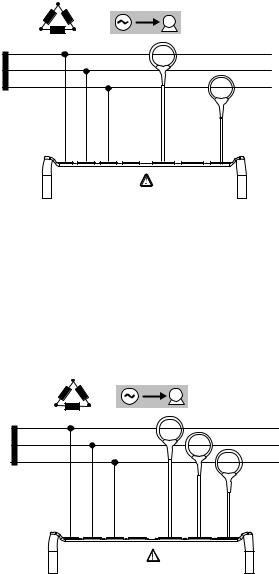
3.6.3.1 3-Phase 3-Wire ∆ (with 2 current sensors)
For 3-Phase 3-Wire ∆ measurements using two current sensors:
■■ Connect the terminal V1 test lead to the L1 phase conductor
■■ Connect the terminal V2 test lead to the L2 phase conductor
■■ Connect the terminal V3 test lead to the L3 phase conductor
■■ Connect the terminal I1 current probe to the LI phase conductor
■■ Connect the terminal I3 current probe to the L3 phase conductor
Ensure that the current arrow on the sensor is directed towards the load. This ensures proper phase angle for power measurements and other phase sensitive measurements.
3.6.3.2 3-Phase 3-Wire ∆ (with 3 current sensors)
L3 |
|
|
|
|
|
|
L2 |
L1 |
|
|
|
|
L1 |
|
|
|
|
|
|
|
|
|
|
|
|
|
L2 |
|
|
|
|
|
|
L3 |
V1 |
V2 |
V3 |
N |
I1 |
I2 |
I3 |
Figure 14
For 3-Phase 3-Wire ∆ measurements using three current sensors:
■■ Connect the terminal V1 test lead to the L1 phase conductor
■■ Connect the terminal V2 test lead to the L2 phase conductor
■■ Connect the terminal V3 test lead to the L3 phase conductor
■■ Connect the terminal I1 current probe to the LI phase conductor.
■■ Connect the terminal I2 current probe to the L2 phase conductor
■■ Connect the terminal I3 current probe to the L3 phase conductor
Ensure that the current arrow on the sensor is directed towards the load. This ensures proper phase angle for power measurements and other phase sensitive measurements.
|
L3 |
|
|
|
|
|
L2 |
L1 |
|
|
|
|
L1 |
|
|
|
|
|
|
|
|
|
|
|
|
|
L2 |
|
|
|
|
|
|
L3 |
V1 |
V2 |
V3 |
N |
I1 |
I2 |
I3 |
Figure 15
Power & Energy Logger Model PEL 102 and PEL 103 |
23 |
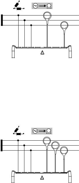
3.6.3.3 3-Phase 3-Wire Open ∆ (with 2 current sensors)
For 3-Phase 3-Wire Open ∆ measurements using two current sensors:
■■ Connect the terminal V1 test lead to the L1 phase conductor
■■ Connect the terminal V2 test lead to the L2 phase conductor
■■ Connect the terminal V3 test lead to the L3 phase conductor
■■ Connect the terminal I1 current probe to the LI phase conductor
■■ Connect the terminal I3 current probe to the L3 phase conductor
Ensure that the current arrow on the sensor is directed towards the load. This ensures proper phase angle for power measurements and other phase sensitive measurements.
3.6.3.4 3-Phase 3-Wire Open ∆ (with 3 current sensors]
For 3-Phase 3-Wire Open ∆ measurements using three current sensors:
■■ Connect the terminal V1 test lead to the L1 phase conductor
■■ Connect the terminal V2 test lead to the L2 phase conductor
■■ Connect the terminal V3 test lead to the L3 phase conductor
■■ Connect the terminal I1 current probe to the LI phase conductor
■■ Connect the terminal I2 current probe to the L2 phase conductor
■■ Connect the terminal I3 current probe to the L3 phase conductor
Ensure that the current arrow on the sensor is directed towards the load. This ensures proper phase angle for power measurements and other phase sensitive measurements.
|
L3 |
|
|
|
|
|
L2 |
L1 |
|
|
|
|
L1 |
|
|
|
|
|
|
|
|
|
|
|
|
|
L2 |
|
|
|
|
|
|
L3 |
V1 |
V2 |
V3 |
N |
I1 |
I2 |
I3 |
Figure 16
|
L3 |
|
|
|
|
|
L2 |
L1 |
|
|
|
|
L1 |
|
|
|
|
|
|
|
|
|
|
|
|
|
L2 |
|
|
|
|
|
|
L3 |
V1 |
V2 |
V3 |
N |
I1 |
I2 |
I3 |
Figure 17
24 |
Power & Energy Logger Model PEL 102 and PEL 103 |

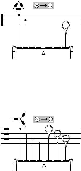
3.6.3.5 3-Phase 3-Wire Y (with 2 current sensors)
For 3-Phase 3-Wire Y measurements using two current sensors:
■■ Connect the terminal V1 test lead to the L1 phase conductor
■■ Connect the terminal V2 test lead to the L2 phase conductor
■■ Connect the terminal V3 test lead to the L3 phase conductor
■■ Connect the terminal I1 current probe to the LI phase conductor
■■ Connect the terminal I3 current probe to the L3 phase conductor
Ensure that the current arrow on the sensor is directed towards the load. This ensures proper phase angle for power measurements and other phase sensitive measurements.
|
L3 |
|
|
|
|
|
L2 |
N |
|
|
|
|
|
|
|
|
|
|
|
|
|
L1 |
|
|
|
|
|
|
|
|
|
|
|
L1 |
|
|
|
|
|
|
L2 |
|
|
|
|
|
|
L3 |
V1 |
V2 |
V3 |
N |
I1 |
I2 |
I3 |
Figure 18
3.6.3.6 3-Phase 3-Wire Y (with 3 current sensors]
For 3-Phase 3-Wire Y measurements using three current sensors:
■■ Connect the terminal V1 test lead to the L1 phase conductor
■■ Connect the terminal V2 test lead to the L2 phase conductor
■■ Connect the terminal V3 test lead to the L3 phase conductor
■■ Connect the terminal I1 current probe to the LI phase conductor
■■ Connect the terminal I2 current probe to the L2 phase conductor
■■ Connect the terminal I3 current probe to the L3 phase conductor
Ensure that the current arrow on the sensor is directed towards the load. This ensures proper phase angle for power measurements and other phase sensitive measurements.
|
L3 |
|
|
|
|
|
L2 |
N |
|
|
|
|
|
|
|
|
|
|
|
|
|
L1 |
|
|
|
|
L1 |
|
|
|
|
|
|
|
|
|
|
|
|
|
L2 |
|
|
|
|
|
|
L3 |
V1 |
V2 |
V3 |
N |
I1 |
I2 |
I3 |
Figure 19
Power & Energy Logger Model PEL 102 and PEL 103 |
25 |
3.6.3.7 3-Phase 3-Wire ∆ Balanced (with 1 current sensor)
For 3-Phase 3-Wire ∆ Balanced measurements using one current sensor:
■■ Connect the terminal V1 test lead to the L1 phase conductor
■■ Connect the terminal V2 test lead to the L2 phase conductor
■■ Connect the terminal I3 current probe to the L3 phase conductor
Ensure that the current arrow on the sensor is directed towards the load. This ensures proper phase angle for power measurements and other phase sensitive measurements.
|
L3 |
|
|
|
|
|
L2 |
L1 |
|
|
|
|
L1 |
|
|
|
|
|
|
|
|
|
|
|
|
|
L2 |
|
|
|
|
|
|
L3 |
V1 |
V2 |
V3 |
N |
I1 |
I2 |
I3 |
Figure 20
3.6.4 3-Phase 4-Wire Y Power Networks
3.6.4.1 3-Phase 4-Wire Y (with 3 current sensors)
For 3-Phase 4-Wire Y measurements using three current sensors:
■■ Connect the terminal N test lead to the neutral conductor
■■ Connect the terminal V1 test lead to the L1 phase conductor
■■ Connect the terminal V2 test lead to the L2 phase conductor
■■ Connect the terminal V3 test lead to the L3 phase conductor
■■ Connect the terminal I1 current probe to the LI phase conductor
■■ Connect the terminal I2 current probe to the L2 phase conductor
■■ Connect the terminal I3 current probe to the L3 phase conductor
Ensure that the current arrow on the sensor is directed towards the load. This ensures proper phase angle for power measurements and other phase sensitive measurements.
|
L3 |
|
|
|
|
|
L2 |
N |
|
|
|
|
|
|
|
|
|
|
|
|
|
L1 |
|
|
|
|
L1 |
|
|
|
|
|
|
|
|
|
|
|
|
|
L2 |
|
|
|
|
|
|
L3 |
|
|
|
|
|
|
N |
V1 |
V2 |
V3 |
N |
I1 |
I2 |
I3 |
Figure 21
26 |
Power & Energy Logger Model PEL 102 and PEL 103 |
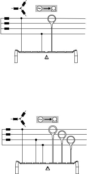
3.6.4.2 3-Phase 4-Wire Y Balanced
For 3-Phase 3-Wire Balanced Y measurements using one current sensor:
■■ Connect the terminal N test lead to the neutral conductor
■■ Connect the terminal V1 test lead to the L1 phase conductor
■■ Connect the terminal I1 current probe to the L1 phase conductor
Ensure that the current arrow on the sensor is directed towards the load. This ensures proper phase angle for power measurements and other phase.
|
L3 |
|
|
|
|
|
L2 |
N |
|
|
|
|
|
|
|
|
|
|
|
|
|
L1 |
|
|
|
|
L1 |
|
|
|
|
|
|
|
|
|
|
|
|
|
L2 |
|
|
|
|
|
|
L3 |
|
|
|
|
|
|
N |
V1 |
V2 |
V3 |
N |
I1 |
I2 |
I3 |
Figure 22
3.6.4.3 3-Phase 4-Wire Y 2½ Element
For 3-Phase 4-Wire Y 2½ Element measurements and using three current sensors:
■■ Connect the terminal N test lead to the neutral conductor
■■ Connect the terminal V1 test lead to the L1 phase conductor
■■ Connect the terminal V3 test lead to the L3 phase conductor
■■ Connect the terminal I1 current probe to the LI phase conductor
■■ Connect the terminal I2 current probe to the L2 phase conductor
■■ Connect the terminal I3 current probe to the L3 phase conductor
Ensure that the current arrow on the sensor is directed towards the load. This ensures proper phase angle for power measurements and other phase sensitive measurements.
|
L3 |
|
|
|
|
|
L2 |
N |
|
|
|
|
|
|
|
|
|
|
|
|
|
L1 |
|
|
|
|
L1 |
|
|
|
|
|
|
|
|
|
|
|
|
|
L2 |
|
|
|
|
|
|
L3 |
|
|
|
|
|
|
N |
V1 |
V2 |
V3 |
N |
I1 |
I2 |
I3 |
Figure 23
Power & Energy Logger Model PEL 102 and PEL 103 |
27 |

3.6.5 3-Phase 4-Wire ∆
High Leg configuration. No Potential Transformer (Voltage Transformer) is connected; the installation under test is supposed to be a low voltage distribution system.
3.6.5.1 3-Phase 4-Wire ∆
For 3-Phase 4-Wire ∆ measurements and using three current sensors:
■■ Connect the terminal N test lead to the neutral conductor
■■ Connect the terminal V1 test lead to the L1 phase conductor
■■ Connect the terminal V2 test lead to the L2 phase conductor
■■ Connect the terminal V3 test lead to the L3 phase conductor
■■ Connect the terminal I1 current probe to the LI phase conductor
■■ Connect the terminal I2 current probe to the L2 phase conductor
■■ Connect the terminal I3 current probe to the L3 phase conductor
Ensure that the current arrow on the sensor is directed towards the load. This ensures proper phase angle for power measurements and other phase sensitive measurements.
3.6.5.2 3-Phase 4-Wire Open ∆
For 3-Phase 4-Wire Open ∆ measurements and using three current sensors:
■■ Connect the terminal N test lead to the neutral conductor
■■ Connect the terminal V1 test lead to the L1 phase conductor
■■ Connect the terminal V2 test lead to the L2 phase conductor
■■ Connect the terminal V3 test lead to the L3 phase conductor
■■ Connect the terminal I1 current probe to the LI phase conductor
■■ Connect the terminal I2 current probe to the L2 phase conductor
■■ Connect the terminal I3 current probe to the L3 phase conductor
Ensure that the current arrow on the sensor is directed towards the load. This ensures proper phase angle for power measurements and other phase sensitive measurements.
L2 |
|
|
|
|
|
|
L1 |
L3 |
|
|
|
|
|
N |
|
|
|
|
|
L1 |
|
|
|
|
|
|
|
|
|
|
|
|
|
L2 |
|
|
|
|
|
|
L3 |
|
|
|
|
|
|
N |
V1 |
V2 |
V3 |
N |
I1 |
I2 |
I3 |
Figure 24
L2 |
|
|
|
|
|
|
L1 |
L3 |
|
|
|
|
|
N |
|
|
|
|
|
L1 |
|
|
|
|
|
|
|
|
|
|
|
|
|
L2 |
|
|
|
|
|
|
L3 |
|
|
|
|
|
|
N |
V1 |
V2 |
V3 |
N |
I1 |
I2 |
I3 |
Figure 25
28 |
Power & Energy Logger Model PEL 102 and PEL 103 |
Loading...