


 Loading...
DIGITAL GROUND RESISTANCE AND SOIL RESISTIVITY TESTERS
4620
4630
E N G L I S H |
User Manual |
|
|
|
|

Statement of Compliance
Chauvin Arnoux®, Inc. d.b.a. AEMC® Instruments certifies that this instrument has been calibrated using standards and instruments traceable to international standards.
We guarantee that at the time of shipping your instrument has met its published specifications.
An NIST traceable certificate may be requested at the time of purchase, or obtained by returning the instrument to our repair and calibration facility, for a nominal charge.
The recommended calibration interval for this instrument is 12 months and begins on the date of receipt by the customer. For recalibration, please use our calibration services. Refer to our repair and calibration section at www.aemc.com.
Serial #: _ ________________________________
Catalog #: _______________________________
Model #: 4620 / 4630
Please fill in the appropriate date as indicated:
Date Received: __________________________________
Date Calibration Due: ________________________
Chauvin Arnoux®, Inc. d.b.a AEMC® Instruments
www.aemc.com

Table of Contents
1. INTRODUCTION.................................................................................. |
3 |
|
1.1 |
International Electrical Symbols................................................ |
4 |
1.2 |
Definition of Measurement Categories...................................... |
4 |
1.3 |
Receiving Your Shipment.......................................................... |
4 |
1.4 |
Ordering Information................................................................. |
5 |
|
1.4.1 Kits, Accessories and Replacement Parts..................... |
6 |
2. PRODUCT FEATURES.......................................................................... |
7 |
||
2.1 |
Control and Connector Features (Model 4620) ........................ |
7 |
|
2.2 |
Control and Connector Features (Model 4630)......................... |
8 |
|
2.3 |
Fault Indicator LEDs.................................................................. |
9 |
|
|
2.3.1 |
X - Z Fault ........................................................................ |
9 |
|
2.3.2 |
Xv - Y High Resistance .................................................... |
9 |
|
2.3.3 |
Xv - Y High Noise ............................................................ |
9 |
2.4 |
Buzzer |
..................................................................................... |
10 |
2.5 |
Over-range ..............................................................Indication |
10 |
|
2.6 |
Fault LED ...............................Indication – Tips and Solutions |
10 |
|
3. SPECIFICATIONS.............................................................................. |
11 |
|
3.1 |
Electrical.................................................................................. |
11 |
3.2 |
Mechanical.............................................................................. |
12 |
3.3 |
Environmental......................................................................... |
13 |
3.4 |
Safety...................................................................................... |
13 |
3.5 |
Auto-ranging............................................................................ |
13 |
4. GROUNDING THEORY....................................................................... |
14 |
|
4.1 |
Grounding Electrode Resistance............................................. |
14 |
|
4.1.1 Effect of Electrode Size/Depth on Resistance............. |
16 |
|
4.1.2 Effects of Soil Resistivity on Electrode Resistance..... |
17 |
|
4.1.3 Factors Affecting Soil Resistivity.................................. |
17 |
|
4.1.4 Effect of Ground Rod Depth on Resistance................ |
20 |
4.2 |
Ground Resistance Values...................................................... |
21 |
4.3 |
Ground Resistance Testing Principle ..................................... |
23 |
|
4.3.1 Position of Auxiliary Electrodes in Measurements....... |
24 |
Digital Ground Resistance Tester Model 4620 and 4630 |
1 |
4.4 |
Measuring Resistance of Ground Electrodes ......................... |
26 |
|
4.4.1 Auxiliary Electrode Spacing......................................... |
28 |
4.5 |
Multiple Electrode System....................................................... |
28 |
5. OPERATION..................................................................................... |
30 |
|
5.1 |
Ground Resistance Measurement Procedure ........................ |
30 |
5.2 |
2-Point Measurement (Simplified Measurement).................... |
31 |
5.3 |
Continuity Measurement......................................................... |
32 |
5.4 |
Soil Resistivity Measurements................................................ |
32 |
|
5.4.1 Purposes of Soil Resistivity......................................... |
32 |
|
5.4.2 Types of Resistivity Measurements............................. |
33 |
5.5 |
Soil Resistivity Measurement Procedure (4-Point).................. |
34 |
5.6 |
How to Use 25ΩCalibration Checker (accessory)................. |
36 |
6. MAINTENANCE................................................................................ |
37 |
|
6.1 |
Warning .................................................................................. |
37 |
6.2 |
Disassembly............................................................................ |
37 |
6.3 |
Power Supply.......................................................................... |
38 |
|
6.3.1 Testing the Battery....................................................... |
38 |
|
6.3.2 Replacing the Battery (Model 4620)............................ |
39 |
|
6.3.3 Recharging the Battery (Model 4630)......................... |
39 |
|
6.3.4 Replacing the Safety Fuse.......................................... |
40 |
6.4 |
Cleaning.................................................................................. |
40 |
6.5 |
Storage.................................................................................... |
40 |
Repair and Calibration..................................................................... |
41 |
|
Technical and Sales Assistance...................................................... |
41 |
|
Limited Warranty.............................................................................. |
42 |
|
Warranty Repairs............................................................................. |
42 |
|
2 |
Digital Ground Resistance Tester Model 4620 and 4630 |

CHAPTER 1
INTRODUCTION
 WARNING
“It should be impressed on all personnel that a lethal potential can exist between the station ground and a remote ground if a system fault involving the station ground occurs while tests are being made. Since one of the objects of tests on a station ground is the establishment of the location of an effectively remote point for both current and potential electrodes, the leads to the electrodes must be treated as though a possible potential could exist between these test leads and any point on the station ground grid.”
- excerpted from IEEE Std. 81-1962
These safety warnings are provided to ensure the safety of personnel and proper operation of the instrument.
•The instrument must not be operated beyond its specified operating range.
•Safety is the responsibility of the operator.
•All metal objects or wires connected to the electrical system should be assumed to be lethal until tested. Grounding systems are no exception.
•Use extreme caution when using the instrument around energized electrical equipment.
•Never attempt to use the instrument to twist or pry the ground electrode or ground wire away from the equipment being grounded.
•AEMC® Instruments considers the use of rubber gloves to be an excellent safety practice even if the equipment is properly operated and correctly grounded.
•Always inspect the instrument and leads prior to use. Replace any defective parts immediately.
Digital Ground Resistance Tester Model 4620 and 4630 |
3 |

1.1International Electrical Symbols
Signifies that the instrument is protected by double or reinforced insulation.
This symbol on the instrument indicates a WARNING and that the operator must refer to the user manual for instructions before operating the instrument. In this manual, the symbol preceding instructions indicates that if the instructions are not followed, bodily injury, installation/sample and/or product damage may result.
Risk of electric shock. The voltage at the parts marked with this symbol may be dangerous.
In conformity with WEEE 2002/96/EC
1.2Definition of Measurement Categories
CAT II: For measurements performed on circuits directly connected to the electrical distribution system. Examples are measurements on household appliances or portable tools.
CAT III: For measurements performed in the building installation at the distribution level such as on hardwired equipment in fixed installation and circuit breakers.
CAT IV: For measurements performed at the primary electrical supply (<1000V) such as on primary overcurrent protection devices, ripple control units, or meters.
1.3Receiving Your Shipment
Upon receiving your shipment, make sure that the contents are consistent with the ordering information. Notify your distributor of any missing items. If the equipment appears to be damaged, file a claim immediately with the carrier and notify your distributor at once, giving a detailed description of any damage. Save the damaged packing container to substantiate your claim.
Do not use equipment which is damaged or appears to be damaged.
4 |
Digital Ground Resistance Tester Model 4620 and 4630 |
1.4Ordering Information
Ground Resistance Tester Model 4620............................ |
Cat. #2130.43 |
Includes 8 C cell batteries and user manual.
Ground Resistance Tester Model 4620 Kit (150 ft).......... |
Cat. #2135.19 |
Includes ground tester, two 150 ft color-coded leads on spools (red/blue), one 30 ft lead (green), two T-shaped auxiliary ground electrodes, set of 5 spaded lugs, one 100 ft AEMC® tape measure, 8 C cell batteries, carrying bag and user manual.
Ground Resistance Tester Model 4620 Kit (300 ft).......... |
Cat. #2135.20 |
Includes ground tester, two 300 ft color-coded leads on spools (red/blue), two 100 ft colorcoded leads (hand-tied, green/black), four T-shaped auxiliary ground electrodes, set of 5 spaded lugs, one 100 ft AEMC® tape measure, 8 C cell batteries, carrying bag and user manual.
Ground Resistance Tester Model 4620 Kit (500 ft).......... |
Cat. #2135.21 |
Includes ground tester, two 500 ft color-coded leads on spools (red/blue), two 100 ft colorcoded leads (hand-tied, green/black), one 30 ft lead (green), four T-shaped auxiliary ground electrodes, set of 5 spaded lugs, one 100 ft AEMC® tape measure, 8 C cell batteries, carrying bag and user manual.
Ground Resistance Tester Model 4630............................ |
Cat. #2130.44 |
Includes rechargeable battery, AC power cord and user manual.
Ground Resistance Tester Model 4630 Kit (150 ft).......... |
Cat. #2135.22 |
Includes ground tester, two 150 ft color-coded leads on spools (red/blue), one 30 ft lead
(green), two T-shaped auxiliary ground electrodes, set of 5 spaded lugs, one 100 ft AEMC® tape measure, rechargeable battery, carrying bag and user manual.
Ground Resistance Tester Model 4630 Kit (300 ft).......... |
Cat. #2135.23 |
Includes ground tester, two 300 ft color-coded leads on spools (red/blue), two 100 ft colorcoded leads (hand-tied, green/black), four T-shaped auxiliary ground electrodes, set of 5 spaded lugs, one 100 ft AEMC® tape measure, rechargeable battery, carrying bag and user manual.
Ground Resistance Tester Model 4630 Kit (500 ft).......... |
Cat. #2135.24 |
Includes ground tester, two 500 ft color-coded leads on spools (red/blue), two 100 ft colorcoded leads (hand-tied, green/black), one 30 ft lead (green), four T-shaped auxiliary ground electrodes, set of 5 spaded lugs, one 100 ft AEMC® tape measure, rechargeable battery, carrying bag and user manual.
Digital Ground Resistance Tester Model 4620 and 4630 |
5 |

1.4.1Kits, Accessories and Replacement Parts
Test Kit for 3-Point Testing (150 ft)................................... |
Cat. #2135.35 |
Includes two 150 ft color-coded leads on spools (red/blue), one 30 ft lead (green), two T- shaped auxiliary ground electrodes, set of 5 spaded lugs, one 100 ft AEMC® tape measure and carrying bag.
Test Kit for 4-Point Testing (300 ft)................................... |
Cat. #2135.36 |
Includes two 300 ft color-coded leads on spools (red/blue), two 100 ft color-coded leads
(hand-tied, green/black), four T-shaped auxiliary ground electrodes, set of 5 spaded lugs, one 100 ft AEMC® tape measure and carrying bag.
Test Kit for 4-Point Testing (500 ft)................................... |
Cat. #2135.37 |
Includes two 500 ft color-coded leads on spools (red/blue), two 100 ft color-coded leads (hand-tied, green/black), one 30 ft lead (green), four T-shaped auxiliary ground electrodes, set of 5 spaded lugs, one 100 ft AEMC® tape measure and carrying bag.
Test Kit for 3-Point Testing (Supplemental for 4-Point Testing)... Cat. #2135.38
Includes two 100 ft color-coded leads (hand-tied, green/black), one 30 ft lead (green), two T-shaped auxiliary ground electrodes, set of 5 spaded lugs, one 100 ft AEMC® tape measure and carrying bag.
25Ω Calibration Checker...................................................... |
Cat. #2130.59 |
Tape Measure – AEMC 100 ft.............................................. |
Cat. #2130.60 |
Set of 2, T-Shaped Auxiliary Ground Electrodes.................. |
Cat. #2135.39 |
Inverter – 12VDC to 120VAC 200 Watt for vehicle use ........ |
Cat. #2135.43 |
Fuse – Set of 5, 0.1A, >250V, 0.25 x 1.25".......................... |
Cat. #2970.12 |
Replacement 9.6V Rechargeable Battery Pack (4630)....... |
Cat. #2960.21 |
115V Power Cord................................................................. |
Cat. #5000.14 |
Download the Ground Tester Workbook at www.aemc.com
Order Accessories and Replacement Parts Directly Online
Check our Storefront at www.aemc.com/store for availability
6 |
Digital Ground Resistance Tester Model 4620 and 4630 |
CHAPTER 2
PRODUCT FEATURES
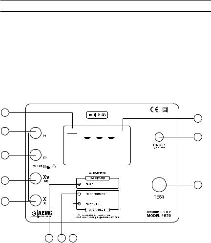
2.1Control and Connector Features
(Model 4620)
1
2 


 3
3 


 Ω
Ω
4
5
9
10
11
|
6 |
7 |
8 |
|
|
|
|
|
|
Figure 1 |
|
1. |
Low battery indicator |
|
7. |
Xv-Y High Resistance indicator |
|
2. |
Input terminal Z (H) |
|
8. |
Xv-Y High Noise indicator |
|
3. |
Input terminal Y (S) |
|
9. |
Display (with backlight - lights up when |
|
4. |
Input terminal Xv (ES) |
|
the TEST button is pressed) |
||
5. |
Input terminal X (E) |
|
10. |
Fuse holder |
|
6. |
X-Z Fault indicator |
|
11. |
TEST button |
|
|
|
|
|
|
(when released, turns the unit OFF) |
Digital Ground Resistance Tester Model 4620 and 4630 |
7 |
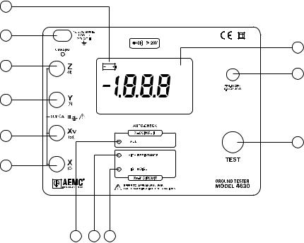
2.2Control and Connector Features
(Model 4630)
1 |
|
2 |
|
|
10 |
3 |
|
|
11 |
4 |
Ω |
5 |
|
|
12 |
6 |
|
7 8 9
Figure 2
1. |
Low battery indicator |
7. |
X-Z Fault indicator |
2. |
AC power input |
8. |
Xv-Y High Resistance indicator |
3. |
Input terminal Z (H) |
9. |
Xv-Y High Noise indicator |
4. |
Input terminal Y (S) |
10. |
Display (with backlight) |
5. |
Input terminal Xv (ES) |
11. |
Fuse holder |
6. |
Input terminal X (E) |
12. |
Test button |
8 |
Digital Ground Resistance Tester Model 4620 and 4630 |
2.3Fault Indicator LEDs
The three indicators confirm that the correct measurement is being taken, if none of them are lit.
2.3.1X-Z Fault
This LED signals that the voltage between terminals X and Z exceeds 30V peak.
There are four possible causes:
•the resistance of the current circuit between X and Z is too high
•interference voltage in the current circuit is too high
•the fuse is blown
•the circuit is open (lead not connected)
2.3.2Xv-Y High Resistance
This LED signals that the resistance in the voltage circuit (between Xv and Y or X and Y) is too high (approx 50kΩ) or that the circuit may be open.
•Flashing will continue throughout the measurement, even if the resistance drops below the threshold (e.g. after reconnecting or lowering auxiliary rod resistance). In this case, you must release the push-button and press again after the fault has been corrected.
•Occasionally, a stray voltage above 4.5V may also set off this light.
•Check the leads for a possible solution.
2.3.3Xv-Y High Noise
This LED signals the presence of excessive electrical noise (13V peak approx) in the voltage circuit (between Xv and Y or X and Y).
•One remedy is to use shielded leads from the instrument to the auxiliary electrodes.
•Connect all the shields to the rod under test.
Digital Ground Resistance Tester Model 4620 and 4630 |
9 |

2.4Buzzer
The Models 4620 and 4630 feature a buzzer, which will sound when the terminals of the tester are connected to a voltage source. The sound volume is proportional to the voltage up to 30V approximately, then becomes stable.
2.5Over-range Indication
Over-range is indicated when the display reads 1, or when the display is blinking and the indicator is lit.
2.6Fault LED Indication – Tips and Solutions
The LED indicators show excessive electrode resistance and excessive transient noise and/or stray current.
In the event of an incorrect measurement indication:
•Improve the quality of the connection to earth of auxiliary ground electrodes Y and Z. Z is the most likely source of problems caused by excessive electrode resistance.
•Check connections for continuity between leads and electrodes.
•Be sure that electrodes are properly inserted; they should be buried as much as possible.
•If high electrode resistance still exists after properly inserting aux-
iliary electrodes into the earth, try pouring water on and around the auxiliary electrodes. This will improve their electrical connection to earth.
•If stray currents are suspected, one solution to reduce their influence is to move both Y and Z electrodes in an arc relative to the X electrode (try, e.g. a 90° shift), and test again.
•Display of 0.00: Xv and Y are short-circuited.
•Display of <0: X and Z or Xv and Y rods are reversed.
NOTE: Accuracy may be affected by auxiliary ground rod (Ry, Rz) resistance levels and by stray signal levels (earth currents).
10 |
Digital Ground Resistance Tester Model 4620 and 4630 |

CHAPTER 3
SPECIFICATIONS
3.1Electrical
Measurement Range: Auto-ranging 0 to 2000Ω
Range |
|
20Ω |
|
200Ω |
|
2000Ω |
Measurement |
|
0 to 19.99Ω |
|
20 to 199.9Ω |
|
200 to 1999Ω |
Resolution |
|
10mΩ |
|
100mΩ |
|
1Ω |
Test Current |
|
10mA |
|
1mA |
|
0.1mA |
Accuracy |
|
2% of Reading ± 1ct |
± 5% of Reading ± 3cts |
|||
Open Voltage |
|
|
|
<42V peak |
|
|
Operating Frequency: 128Hz square wave |
|
|
||||
Max. Auxiliary Rod Resistance: |
|
|
|
|
||
|
|
|
|
|
|
|
Range |
|
20Ω |
|
200Ω |
|
2000Ω |
Current Circuit |
|
3kΩ |
|
30kΩ |
|
50kΩ |
Voltage Circuit |
|
|
|
50kΩ |
|
|
Response Time: 4 to 8 seconds approx for a stabilized measurement
Interference:
The Models 4620 & 4630 are designed to reject high levels of interference voltage (DC, 50/60Hz, harmonics)
•DC voltage in series with X: 20V
•AC voltage in series with Y: 13V peak (@ 16.67, 50, 60, 400Hz)
•AC voltage in series with Z: 32V peak (@ 16.67, 50, 60, 400Hz)
Accuracies and specifications are given for an ambient temperature of 23°C ±3°K, RH of
45 to 55%, battery power at 9.5V, auxiliary resistance at the measurement terminals = 0, no stray voltage, an electrical field < 1V/m, and a magnetic field from 0 to 40A/m.
Voltage Detection Range: 20 to 250VAC between the X and Z terminals or between the Xv and Z terminals.
Frequency: DC at 450Hz
Voltage Withstanding: Both models are fuse protected. In the event of a system fault, the units can withstand 250VAC or 100VDC.
Fuse Protection: High breaking capacity - 0.1A, >250V, 0.25 x 1.25"
Digital Ground Resistance Tester Model 4620 and 4630 |
11 |
Model 4620
Power Source: Eight 1.5V C cell batteries
Battery Life: 4500 measurements of 15 seconds each
Low Battery Indicator: If the indicator lights up, the batteries are losing power.
Model 4630
Power Source: NiMH rechargeable cell (4630) Battery Life: 2000 measurements of 15 seconds each
Battery Charging:
External recharge - 120-230V/50-60Hz, 20VA
Charge time - 6 hrs to attain 80% of the battery capacity
Low Battery Indicator: If the “CHARGE” indicator turns on solid RED, the battery needs to be charged.
3.2Mechanical
Connection:
Color-coded terminals accept spade lugs with minimum gap of 6mm or standard 4mm banana jacks.
Display:
2000-count 7 segment LCD, approx 1" high (3-1/2 digit)
LCD also indicates overrange, test lead shorts and lead reversals. Blue electroluminescent backlight.
Dimensions:
10.8 x 9.7 x 5.0" (273 x 247 x 127mm)
Weight:
Model 4620: 6.28 lbs (2.85kg) Model 4630: 7.38 lbs (3.35kg)
Colors:
Case - safety yellow; Front panel - gray
Mechanical Protection:
The Models 4620 and 4630 have successfully undergone all the required mechanical tests and therefore meet all the requirements of the standards EN 61557 and EN 61010-1.
12 |
Digital Ground Resistance Tester Model 4620 and 4630 |

3.3Environmental
Operating Temperature:
14° to 131°F (-10° to 55°C), 0 to 90% RH
Storage Temperature:
-40° to 158°F (-40° to 70°C), 0 to 90% RH with batteries removed
3.4Safety
Electrical:
EN 61010-1 + A2 (ed. 95) EN 61557 (ed. 97)
30Vrms, CAT III, Pollution Degree 2
Electromagnetic Compatibility:
EN 61326-1 (ed.98)
*Specifications are subject to change without notice
3.5Auto-ranging
The selection of the measurement current is depending on the resistance to measure.
When the instrument is turned ON, the measurement starts on the smallest current range (100µA). If the measurement is between 185 and 1950cts, the range stays the same (100µA). If the measurement is under 185cts, the current is multiplied by 10 (within 10mAmax). If it is above 1950cts, the current is divided by 10 (without going under 100µA).
This is done to avoid switching back and forth between ranges when you are measuring 190W. It is possible to display 190.0 or 190W depending on the automatic range selection.
Digital Ground Resistance Tester Model 4620 and 4630 |
13 |
Loading...