


 Loading...
|
MICRO-OHMMETER |
6250 |
|
||
|
|
|
E N G L I S H |
User Manual |
|
|
|
|

Statement of Compliance
Chauvin Arnoux®, Inc. d.b.a. AEMC® Instruments certifies that this instrument has been calibrated using standards and instruments traceable to international standards.
We guarantee that at the time of shipping your instrument has met its published specifications.
An NIST traceable certificate may be requested at the time of purchase, or obtained by returning the instrument to our repair and calibration facility, for a nominal charge.
The recommended calibration interval for this instrument is 12 months and begins on the date of receipt by the customer. For recalibration, please use our calibration services. Refer to our repair and calibration section at www.aemc.com.
Serial #: _ ________________________________
Catalog #: 2129.81 Model #: 6250
Please fill in the appropriate date as indicated:
Date Received: __________________________________
Date Calibration Due: ________________________
Chauvin Arnoux®, Inc. d.b.a AEMC® Instruments
www.aemc.com

READ CAREFULLY BEFORE
USING FOR THE FIRST TIME
Your instrument is equipped with a NiMH battery. This technology offers several advantages:
•Long battery charge life for a limited volume and weight.
•Possibility of quickly recharging your battery.
•Significantly reduced memory effect: you can recharge your battery even if it is not fully discharged.
•Respect for the environment: no pollutant materials such as lead or cadmium, in compliance with the applicable regulations.
After prolonged storage, the battery may be completely discharged. If so, it must be completely recharged.
Your instrument may not function during part of this recharging operation.
Full recharging of a completely discharged battery may take several hours.
NOTE: In this case, at least 5 charge/discharge cycles will be necessary for your battery to recover 95% of its capacity.
To make the best possible use of your battery and extend its effective service life:
•Only use the charger supplied with your instrument. Use of another charger may be dangerous.
•Only charge your instrument at temperatures between 0° and 40°C.
•Comply with the conditions of use defined in the operating manual.
•Comply with the storage conditions specified in the operating manual.
NiMH technology allows a limited number of charge/discharge cycles depending significantly on:
•The conditions of use.
•The charging conditions.
Please refer to § 9 for correct replacement of the battery.
Do not dispose of the battery pack with other solid waste. Used batteries must be entrusted to a qualified recycling company or to a company specialized in processing hazardous materials.

|
Table of Contents |
|
1. INTRODUCTION.................................................................................. |
5 |
|
1.1 |
International Electrical Symbols................................................ |
6 |
1.2 |
Definition of Measurement Categories...................................... |
6 |
1.3 |
Receiving Your Shipment.......................................................... |
6 |
1.4 |
Ordering Information................................................................. |
7 |
|
1.4.1 Accessories and Replacement Parts............................ |
7 |
2. PRODUCT FEATURES.......................................................................... |
8 |
|
2.1 |
Description................................................................................ |
8 |
2.2 |
Applications............................................................................... |
9 |
2.3 |
Key Features............................................................................. |
9 |
2.4 |
Control Features...................................................................... |
10 |
2.5 |
Button Functions..................................................................... |
11 |
2.6 |
Display Symbols...................................................................... |
12 |
3. SPECIFICATIONS.............................................................................. |
14 |
|
3.1 |
Electrical.................................................................................. |
14 |
3.2 |
Mechanical.............................................................................. |
15 |
3.3 |
Display..................................................................................... |
15 |
3.4 |
Environmental......................................................................... |
16 |
3.5 |
Safety...................................................................................... |
16 |
4. OPERATION..................................................................................... |
17 |
|
4.1 |
Quick Summary....................................................................... |
17 |
4.2 |
Instrument Configuration (SET-UP Mode)............................... |
19 |
|
4.2.1 Program Menu Tree..................................................... |
19 |
|
4.2.2 Programming the 9-Pin Interface Port (rS) ................. |
20 |
|
4.2.3 Setting the Buzzer Level (bUZZ)................................. |
21 |
|
4.2.4 Reading the Internal Serial Number (EdSn)................ |
21 |
|
4.2.5 Reading the Internal Software Version (EdPP)........... |
21 |
|
4.2.6 Setting Language for Printing Reports (LAnG)............ |
22 |
2 |
Micro-Ohmmeter Model 6250 |
|
4.2.7 |
Setting the Value for Reference Temperature............. |
22 |
|
4.2.8 |
Selecting the Method/Value for Ambient Temp............ |
23 |
|
4.2.9 |
Selecting the Metal Type (nEtA).................................. |
24 |
|
4.2.10 |
Programming the Alpha Value (ALPH)........................ |
24 |
|
4.2.11 |
Selecting Temperature Units (dEg).............................. |
24 |
|
4.2.12 |
Setting Alarm Set Point/Direction/Buzzer Level.......... |
25 |
|
4.2.13 |
Setting the Display Timeout (LlgH).............................. |
26 |
|
4.2.14 |
Clearing the Memory (nEn)......................................... |
26 |
4.3 |
Operating Procedure............................................................... |
28 |
|
|
4.3.1 |
Connections and Readings......................................... |
28 |
|
4.3.2 |
Test Lead Connection.................................................. |
29 |
|
4.3.3 |
Very Low Resistance................................................... |
29 |
|
4.3.4 |
Meter Readings........................................................... |
29 |
|
4.3.5 |
Stand-by (ST BY) State .............................................. |
30 |
4.4 |
Selecting the Test Range........................................................ |
30 |
|
4.5 |
Measurement Modes............................................................... |
31 |
|
|
4.5.1 |
Measurement Safety Warnings................................... |
31 |
|
4.5.2 |
Inductive Resistance Measurement Mode.................. |
31 |
|
4.5.3 |
Resistance Measurement Mode.................................. |
33 |
|
4.5.4 |
Low Inductive Resistance Measurement Mode........... |
34 |
4.6 |
Ambient Temperature Compensation...................................... |
35 |
|
|
4.6.1 |
Activating the Compensation Function ....................... |
38 |
4.7 |
Activating Alarms..................................................................... |
39 |
|
5. MEMORY / PRINTING....................................................................... |
40 |
|
5.1 |
Managing and Printing the Data in Memory .......................... |
40 |
5.2 |
Displaying and Printing Stored Measurements................................ |
41 |
5.3 |
Cables and Printers Used with the Interface Port................... |
43 |
6. DATAVIEW® SOFTWARE................................................................... |
45 |
|
6.1 |
Installing DataView®................................................................ |
45 |
6.2 |
Connecting the Instrument to your Computer......................... |
49 |
6.3 |
Establishing Communication to the Instrument....................... |
49 |
6.4 |
Configuring the Instrument...................................................... |
50 |
6.5 |
Downloading Stored Tests....................................................... |
52 |
Micro-Ohmmeter Model 6250 |
3 |
6.6 |
Creating a DataView® Report.................................................. |
52 |
6.7 |
Exporting the Report to a Spreadsheet or PDF File............... |
53 |
7. TROUBLESHOOTING......................................................................... |
54 |
|
7.1 |
Fault Indicators........................................................................ |
54 |
8. APPLICATION EXAMPLES................................................................ |
55 |
|
8.1 |
Measuring Winding Resistance of Motors |
|
|
and Transformers.................................................................... |
55 |
8.2 |
Measuring Resistance on Electric Motors............................... |
56 |
8.3 |
Battery Strap Measurements................................................... |
56 |
9. MAINTENANCE................................................................................ |
57 |
|
9.1 |
Warning................................................................................... |
57 |
9.2 |
Cleaning.................................................................................. |
57 |
9.3 |
Charging/Recharging the Battery............................................ |
58 |
9.4 |
Battery and Fuse Replacement............................................... |
59 |
Repair and Calibration..................................................................... |
60 |
|
Technical and Sales Assistance...................................................... |
60 |
|
Limited Warranty.............................................................................. |
61 |
|
Warranty Repairs............................................................................. |
61 |
|
4 |
Micro-Ohmmeter Model 6250 |

CHAPTER 1
INTRODUCTION
 WARNING
These safety warnings are provided to ensure the safety of personnel and proper operation of the instrument.
•Do not attempt to perform any tests with this instrument until you have read the user manual.
•Tests are to be carried out on de-energized circuits only! Never connect the unit to a live circuit.
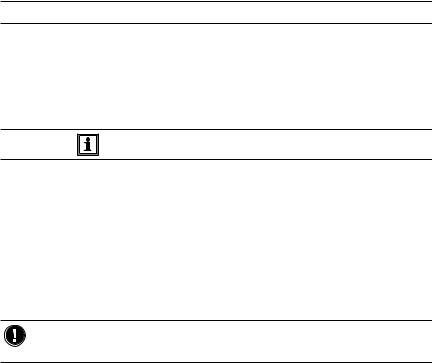
•When the unit is measuring resistance showing a high inductive component (transformers, motors, etc.) after ending the measurement, the unit then discharges the inductive sample and the warning icon  appears for the entire duration. Never disconnect the connection wires before this icon disappears.
•The micro-ohmmeter should never be used in an explosive environment (this includes poorly ventilated battery rooms and enclosures).
•Make sure the internal battery is fully charged prior to testing. If the instrument has been left unused for several months, recharge the battery.
•We recommend recharging the micro-ohmmeter every month to ensure a full battery charge when used.
•When replacing fuses, install only fuses which are direct replacements.
•If the case needs cleaning, do not use any alcohol or oil based cleaners. Preferably use soapy water with a damp cloth or sponge.
•The test leads and measuring wires must be in good condition and should be changed if there is any evidence of deterioration (insulation split, burnt, etc.).
•Never exceed the safety values indicated in the specifications.
Micro-Ohmmeter Model 6250 |
5 |
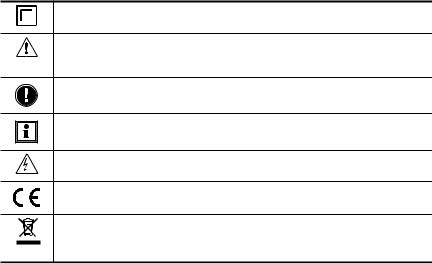
1.1International Electrical Symbols
This symbol signifies that the instrument is protected by double or reinforced insulation.
CAUTION - Risk of Danger! Indicates a WARNING and that the operator must refer to the user manual for instructions before operating the instrument in all cases where this symbol is marked.
Important instructions to read and understand completely.
Important information to acknowledge.
Risk of electric shock. The voltage at the parts marked with this symbol may be dangerous.
Compliance with the Low Voltage & Electromagnetic Compatibility European directives (73/23/CEE & 89/336/CEE)
In the European Union, this product is subject to a separate collection system for recycling electrical and electronic components In accordance with directive WEEE 2002/96/EC
1.2Definition of Measurement Categories
CAT II: For measurements performed on circuits directly connected to the electrical distribution system. Examples are measurements on household appliances or portable tools.
CAT III: For measurements performed in the building installation at the distribution level such as on hardwired equipment in fixed installation and circuit breakers.
CAT IV: For measurements performed at the primary electrical supply
(<1000V) such as on primary overcurrent protection devices, ripple control units, or meters.
1.3Receiving Your Shipment
Upon receiving your shipment, make sure that the contents are consistent with the packing list. Notify your distributor of any missing items. If the equipment appears to be damaged, file a claim immediately with the carrier and notify your distributor at once, giving a detailed description of any damage. Save the damaged packing container to substantiate your claim.
6 |
Micro-Ohmmeter Model 6250 |

1.4Ordering Information
Micro-ohmmeter Model 6250............................................ |
Cat. #2129.81 |
Includes extra large tool bag, set of two 10ft Kelvin clips (10A - Hippo), one RS-232 DB9 F/F
6 ft null modem cable, RS-232 to USB adapter, US 115V power cord, quick reference guide, one pad of measurement result forms, NiMH rechargeable 6V battery pack, and USB stick supplied with product user manual and DataView® software.
1.4.1 Accessories and Replacement Parts
Kelvin clips (10A Hippo), 10 ft color-coded leads................. |
Cat. #1017.84 |
Kelvin clips (10A Hippo), 20 ft color-coded leads................. |
Cat. #2118.70 |
Kelvin probes (1A), spring loaded, 10 ft color-coded leads |
Cat. #2118.73 |
with banana plug terminations............................................. |
|
Kelvin probes (1A), spring loaded, 20 ft color-coded leads |
Cat. #2118.74 |
with banana plug terminations............................................. |
|
Kelvin Probes Pistol Grip 10 ft (10A) Spring Loaded........... |
Cat. #2118.75 |
Kelvin Probes Pistol Grip 20 ft (10A) Spring Loaded........... |
Cat. #2118.76 |
Kelvin Probes 10 ft (10A) Spring Loaded ........................... |
Cat. #2118.77 |
Kelvin Probes 20 ft (10A) Spring Loaded ........................... |
Cat. #2118.78 |
Kelvin Clips 10 ft (1-10A)..................................................... |
Cat. #2118.79 |
Kelvin Clips 20 ft (1-10A)..................................................... |
Cat. #2118.80 |
Cable, PC RS-232, DB9 F/F 6 ft Null Modem Cable........... |
Cat. #2119.45 |
Replacement Battery 6V, 8.5 Ah rechargeable NiMH .......... |
Cat. #2129.91 |
RTD temperature probe....................................................... |
Cat. #2129.95 |
RTD temperature probe with 7 ft (2m) extension cable....... |
Cat. #2129.96 |
Fuse, set of 3, 16A/250V, 1 1/4 x 1/4" (6.3x32mm) |
Cat. #2129.98 |
fast blow....................................................................................... |
|
Fuse, set of 10, 2A/250V, 3/4 x 3/16" (5x20mm) fast blow.. |
Cat. #2129.99 |
Extra large classic tool bag.................................................. |
Cat. #2133.73 |
Inverter – 12VDC to 120VAC 200 Watt for vehicle use......... |
Cat. #2135.43 |
115V Power Cord ................................................................ |
Cat. #5000.14 |
Adapter – RS-232 to USB 2.0 ............................................. |
Cat. #5000.60 |
Order Accessories and Replacement Parts Directly Online
Check our Storefront at www.aemc.com/store for availability
Micro-Ohmmeter Model 6250 |
7 |

CHAPTER 2
PRODUCT FEATURES
2.1Description
The Model 6250 Micro-ohmmeter is used to perform low resistance measurements from 1μΩ to 2500Ω. There are seven ranges with test currents from 1mA to 10A.
The front end of the micro-ohmmeter employs a four-wire Kelvin configuration, which eliminates test lead resistance for a measurement accuracy of 0.05%. A built-in circuit filters out AC signals.
The Model 6250 Micro-ohmmeter is packaged in a sealed field case well suited for shop and field use. Power is supplied by a long-life NiMH battery pack with a built-in recharger (110/220V).
The large, easy-to-read liquid crystal display is 2.25 x 4.00". It displays the value of resistance, metal type, reference and ambient temperatures (if selected), alarm conditions (if selected), test current and range and test mode (Resistive, Inductive or Auto).
For operator safety and instrument protection, the micro-ohmmeter is fuse protected at the inputs. Two fuses, accessible behind the front panel, protect against stored energy in inductive loads.
Enhanced internal circuitry protects against possible inductive kickback when the current is shut off.
A built-in thermal switch protects the micro-ohmmeter against overheating on the 10A range when in continuous use.
8 |
Micro-Ohmmeter Model 6250 |
2.2Applications
Some of the more popular and most frequent uses of the micro-ohmmeter are in applications for:
•Checking metallic coating resistance, especially in aeronautics
•Ground connections and continuity measurement
•Resistance measurements on motors and transformers
•Contact resistance measurements on breakers and switches
•Component measurement
•Electrical cable resistance measurement
•Mechanical bond tests
•Wire to terminal connections
•Aircraft and rail bonds
•Many other very low resistance samples
2.3Key Features
•Measures from 1µΩ to 2500Ω
•Test current selection from 1mA to 10A
•RTD temperature measurement (optional)
•Automatic or manual temperature compensation
•Two programmable alarms with high or low triggering
•Stores up to 1500 test results
•Selectable Inductive or Resistive test modes
•Operator safety by automatic discharge of residual charge on the equipment under test
•Instantaneous, continuous or multiple test operation
•Selectable metal type (Copper, Aluminum or other) for temperature compensation
•Internal, rechargeable batteries conduct up to 5000, 10A tests
•A built-in battery pack recharger recharges the batteries by connecting to the AC line (90V/264V, 45Hz/420Hz) using a standard line cord
•4-Wire measurement with automatic compensation of undesirable voltages and lead resistance
•Large multi-function backlit display
•Direct display of the measurement with its units, range, measurement mode and, if activated, temperature compensation.
•Measurement can be initiated from the front panel or remotely through the 9-pin communication port
•Rugged, sealed case
Micro-Ohmmeter Model 6250 |
9 |

2.4Control Features
2 |
3 |
4 |
5 |
6
1
7
8
Figure 2-1
1.Kelvin input terminals
2.AC line recharging receptacle
3.Large multi-line backlit liquid crystal display
4.RTD temperature input
5.Communication/remote operation port
6.Range selection switch
7.Test, Start/Stop button
8.Eight program/function buttons
10 |
Micro-Ohmmeter Model 6250 |
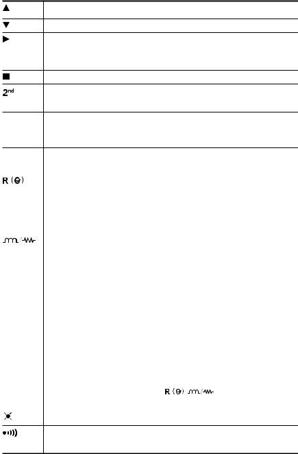
2.5Button Functions
In SET-UP mode, selects a function or increments a flashing parameter.
In SET-UP mode, selects a function or decrements a flashing parameter
In SET-UP mode, accesses the function to be modified.
In Wrap-Around mode, selects the parameter to be modified (from left to right)
In SET-UP mode, shifts the decimal point and selects the unit.
Activates the secondary function of a button. The  symbol appears on the left side of the display.
PRINT Immediate printing of the measurement to a serial printer. If the temperature compensation function has been activated, the calculated result and the temperatures involved are also printed.
Retrieves stored data for printing (this function is independent of the setting |
||||||
MEM |
of the switch) except in the OFF and SET-UP positions. |
|||||
|
|
|
|
Activates or deactivates the temperature compensation function to calcu- |
||
|
|
|
|
late the resistance measured at a temperature other than ambient meas- |
||
|
|
|
|
urement temperature. |
|
|
ALARM |
Activates or deactivates the alarms. High or low triggering values are |
|||||
|
|
|
|
adjusted in SET-UP. |
|
|
|
|
|
|
Selects the desired measurement mode prior to starting one of the follow- |
||
|
|
|
|
ing measurements: Inductive mode (continuous test), non-inductive mode |
||
|
|
|
|
(instantaneous test) or non-inductive mode with automatic triggering (mul- |
||
|
|
|
|
tiple tests). |
|
|
|
|
|
|
|
||
METAL |
Selects the metal type for the temperature compensation calculation: Cu, |
|||||
|
|
|
|
Al, or Other metal. |
|
|
MEM |
Stores the measurement at an address identified by an object number |
|||||
|
|
|
|
(OBJ) and a test number (TEST). |
|
|
|
|
|
|
Two presses on this button are required, one to select the location (use |
||
|
|
|
|
the ▲ and ► buttons to change the location) and another to store the |
||
|
|
|
|
measurement. |
|
|
MR |
Retrieves stored data (this function is independent of the selector setting |
|||||
|
|
|
|
of the switch) except for the OFF and SET-UP positions. Data is viewed |
||
|
|
|
|
using the ▲ and ► buttons. The |
, |
and ALARM buttons can |
|
|
|
|
be used. |
|
|
|
|
|
|
Turns the display backlight ON or OFF. |
|
|
|
|
|
|
|
|
|
|
|
|
|
|
|
|
Activates or deactivates the buzzer and adjusts the sound level.
Micro-Ohmmeter Model 6250 |
11 |
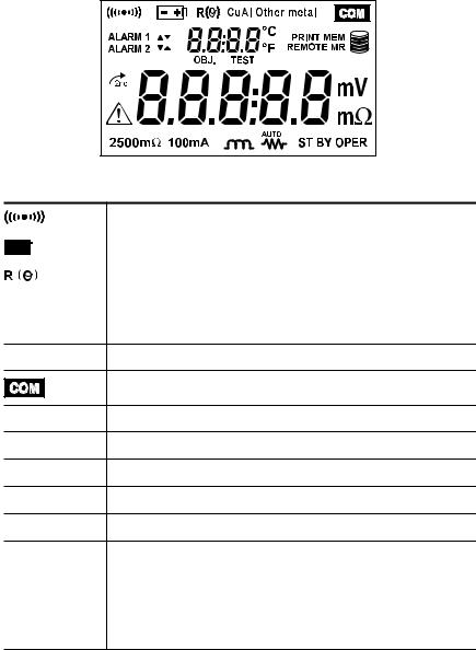
2.6Display Symbols
The display incorporates two lines of characters to display test results, as well as a library of symbols to assist the operator in determining conditions at a glance. The symbols that can appear are shown in Figure 2-2 and are detailed here.
Figure 2-2 |
|
|
|
|
|
|
Buzzer ON |
|
|
|
|
|
|
|
|
|
|
|
|
|
Battery condition |
|
|
|
|
|
|
|
|
|
|
|
|
|
|
|
|
|
|
|
|
Temperature compensation ON |
|
|
|
|
|
|
|
Cu |
|
Copper metal type selected |
||||
|
|
|
|
|
|
|
Al |
|
Aluminium metal type selected |
||||
Other metal User defined metal type selected
Communication port active
ALARM 1 ▲ Alarm 1 active with high set point
ALARM 1 ▼ Alarm 1 active with low set point
ALARM 2 ▲ Alarm 2 active with high set point
ALARM 2 ▼ Alarm 2 active with low set point
OBJ. First position locator for data stored in memory
TEST |
Second position locator for data stored in memory |
|
|
°C / °F |
Temperature displayed in either degrees Centigrade or Fahrenheit |
|
|
Printing current test result or tests stored in memory |
|
|
|
MEM |
Displayed measurement about to be stored in memory |
12 |
Micro-Ohmmeter Model 6250 |

REMOTE |
Instrument under computer control |
|
|
|
|
MR |
|
Memory recall |
|
|
|
|
|
Memory utilization indicator |
|
|
|
mV mΩ |
|
Units of measure |
|
|
|
|
|
Resistive material test mode selected |
|
|
|
|
|
Inductive material test mode selected |
|
|
|
AUTO |
|
Repetitive test mode selected |
|
|
|
ST BY |
|
System idle ready to start a test |
|
|
|
OPER |
|
Test in process |
|
|
|
|
|
Second function of a button activated |
|
|
|
|
|
CAUTION! Refer to the user manual before using the instrument. |
|
|
|
2500Ω 1mA |
2500 ohm, 1 milliamp test range selected |
|
|
|
|
250Ω 10mA |
250 ohm, 10 milliamp test range selected |
|
|
|
|
25Ω 100mA |
25 ohm, 100 milliamp test range selected |
|
|
|
|
2500mΩ 1A |
2500 milliohm, 1 Amp test range selected |
|
|
|
|
250mΩ 10A |
250 milliohm, 10 Amp test range selected |
|
|
|
|
25mΩ |
10A |
25 milliohm, 10 Amp test range selected |
|
|
|
5mΩ |
10A |
5 milliohm, 10 Amp test range selected |
Micro-Ohmmeter Model 6250 |
13 |

CHAPTER 3
SPECIFICATIONS
3.1Electrical
Specifications are given for an ambient temperature of 23°C ± 5°, relative humidity of 45 to 75% and a supply voltage of 6V ± 0.1V.
Measurement Method:
4-Wire Kelvin resistance measurement with compensation for stray/residual voltages
Measurement Ranges:
Range |
Resolution |
Accuracy over 1 year |
Measurement |
Voltage |
|
23°C ± 5°C |
Current |
Drop |
|||
|
|
||||
|
|
|
|
|
|
5mΩ |
0.1µΩ |
0.15% ± 1.0µΩ |
10A |
50mV |
|
25mΩ |
1µΩ |
0.05% ± 3µΩ |
10A |
250mV |
|
250mΩ |
10µΩ |
0.05% ± 30µΩ |
10A |
2500mV |
|
2500mΩ |
0.1mΩ |
0.05% ± 0.3mΩ |
1A |
2500mV |
|
25Ω |
1mΩ |
0.05% ± 3mΩ |
100mA |
2500mV |
|
250Ω |
10mΩ |
0.05% ± 30mΩ |
10mA |
2500mV |
|
2500Ω |
100mΩ |
0.05% ± 300mΩ |
1mA |
2500mV |
Temperature Measurement: 3-wire 100Ω Platinum RTD Accuracy: ± 0.5°C
Resolution: 0.1°C
Influence From Environment Conditions: Temperature: 0.1% per 10°C typical, 0.25% max
Humidity: 0.5% max from 10 to 90% Battery Voltage: ± 0.1% from 4.5 to 7.5V
Open Circuit Voltage: 7VDC max
14 |
Micro-Ohmmeter Model 6250 |
Operating Voltage: 5 to 6VDC
Power Source:
Rechargeable 6V, 8.5 Ah NiMH battery pack
Built-in 90 to 256V (45 to 420Hz) charger
Battery Life: 5000, 10A tests (typical)
Battery Charging: 120/240VAC ± 20% (45 to 400Hz) line voltage
Auto-Power Off: when battery voltage <5.0V
Low Battery Indication: The  symbol is displayed when the battery needs to be recharged
Overload Input Protection: 250Vrms
Fuses:
F1 - 1 1/4 x 1/4" (6.3x32mm), fast acting, 16A/250V current source protection
F2 - 3/4 x 3/16" (5x20mm), fast acting, 2A/250V charging circuit protection
3.2Mechanical
Dimensions: 10.63 x 9.84 x 7.09" (270 x 250 x 180mm)
Weight: 8.1 lbs (3.69kg approx) without leads
Case Protection: ABS plastic polycarbonate: watertight to IP64 (cover closed), water resistant to IP53 (cover open).
Color: Safety yellow case with gray faceplate
3.3Display
Blue Electroluminescent backlit Liquid Crystal Display (LCD), 2.25 x 4.00" with icons and two numeric fields for data presentation.
One numeric field contains 4 digits for displaying ambient and reference temperature levels on the top line in “temperature compensation” mode. The other contains 5 digits and is used to display the measured values on the bottom line. Error messages are also listed on the bottom line.
Micro-Ohmmeter Model 6250 |
15 |

3.4Environmental
Operating Temperature:
14° to 132°F (-10° to 55°C), 10 to 80% (non-condensing) Storage Temperature: -40° to 140°F (-40° to 60°C)
3.5Safety
EN 61010-1, 50V, CAT III, Pollution Degree 2
Conducted and radiated emission:
EN 55022, class B
EN 61000-3-2
EN 61000-3-3
Immunity:
EN 61000-4-2 electrostatic discharges
EN 61000-4-3 radiated fields
EN 61000-4-5 shock
EN 61000-4-6 conducted disturbances
EN 61000-4-11 voltage drops
EN 61000-4-4 bursts
*Specifications are subject to change without notice
16 |
Micro-Ohmmeter Model 6250 |
CHAPTER 4
OPERATION
NOTE: Charge the instrument fully before use.
4.1Quick Summary
The following is a summary instruction set that will assist the operator in performing measurements. For complete details on each function and test method refer to the operating procedure section (§ 4.3) and instrument configuration section (§ 4.2) in this manual.
WARNING: Read and follow all safety warnings on page 4 before operating this instrument.
1.Turn the instrument on and select a test range by turning the rotary switch to the desired position. If the resistance of the device under test is unknown, start with the highest range (2500Ω) and work down to increase resolution as necessary.
2.Select the test method best suited for the measurement by press-
ing the 

 button to select inductive (continuous test), resistive (instantaneous test) or AUTO (multiple testing).
3.Activate the backlight, if necessary, by pressing the  button.
4.Activate the buzzer, if desired, by pressing yellow 
 button followed by the
 button.
5.Activate alarms, if desired, by pressing the yellow 
 button followed by the ALARM button. Successive presses of this two-button sequence will select Alarm 1, Alarm 2 or both.
6.Select the metal type for the device under test by pressing the yellow 
 button followed by the METAL button. Successive presses of this two-button sequence will select Copper (Cu), Aluminum (Al) or Other metal. This will be needed for temperature compensation.
Micro-Ohmmeter Model 6250 |
17 |
7.Activate temperature compensation by pressing the 

 button. The reference temperature will appear followed by the ambient temperature on the top line of the display.
8.Start the test by pressing the START/STOP button. The resistance reading will appear on the lower line of the display. The symbol OPER will appear on the lower left to indicate that a test is in process. The Stand-by symbol STBY will appear when the test is completed. Resistive element tests will stop automatically. Inductive and AUTO testing will stop when the operator pushes the START/ STOP button a second time.
9.Store the test result in memory by pressing the MEM button at the conclusion of a test. The next available location will be presented on the top line of the display. To use this location, press the MEM button a second time.
10.Recall readings from memory by pressing the yellow 
 button followed by the MEM button. The last measurement stored in location
OBJ: X TEST: X will be displayed. Use the ▲, ▼ and ► buttons to select the object and test memory location to review. All information from the measurement is available for review including metal type, ambient and reference temperatures, resistance at ambient and reference temperatures, test range and test current.
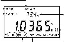
|
Typical Operational Display |
Temperature |
|
compensation active |
|
Buzzer active |
Metal type (Copper) |
Alarm 1 hi set point active |
Reference temperature |
|
Resistance measurement |
|
Measurement units |
Measurement range |
Test in process |
Test current |
Inductive test mode |
|
Figure 4-1 |
18 |
Micro-Ohmmeter Model 6250 |
Loading...