

Operating Instructions
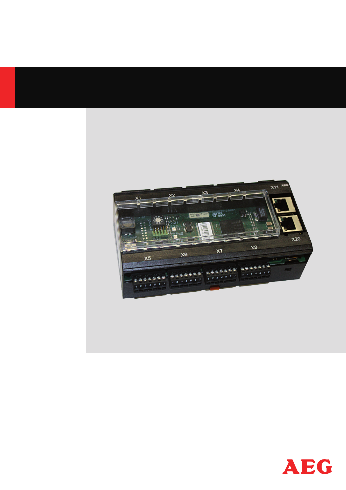
Ethernet Bus Module Profi Net
• Thyro-S ...H1, ..HRL1
• Thyro-A ...H1, ..HRL1, ..HRLP1
• Thyro-A …C01, ..C02, ..C03, ..C05, ..C07
• Thyro-Power Manager
• Thyro-Step Controller
• Thyro-Measurement Unit
PERFECT IN FORM AND FUNCTION

Contents
1. Introduction 5
1.1 General 5
1.2 Special features 5
1.3 Type designation 5
1.4 Abbreviations 5
1.5 Warranty 5
2. Safety 6
2.1 Identification in the operating instructions 6
2.2 General danger information 6
2.3 Operator requirements 7
2.4 Personnel requirements 7
2.5 Intended use 7
2.6 Use of the device 7
2.6.1 Operation 7
2.6.2 Prior to installation / commissioning 8
2.6.3 Maintenance, service, faults 8
2.6.4 Transport 8
3. Functions 9
3.1 Processing the setpoint Thyro-S 9
3.2 Processing the setpoint Thyro-A 9
3.3 Processing the setpoint Thyro-Step Controller 10
3.4 Freely addressable digital outputs 10
4. Installation 11
4.1 Connection terminals (overview) 11
4.2 Connecting a 24 V power supply 11
4.3 Connecting the power controller to X1-X8 11
4.4 Connecting the Ethernet bus module to the master 11
5. Settings 12
5.1 Setting the protocol 12
5.2 Setting the number of slots 12
5.3 Setting the device name 12
5.4 Operating display of the bus module 13
6. Operation 14
6.1 Start configuration (parameterization) 14
6.2 Cyclical data transmission (configuration) 14
6.3 Input and output data Thyro-S 14
6.4 Input and output data Thyro-A 16
6.5 Input and output data Thyro-Power Manager 23
6.6 Input and output data Thyro-Step Controller 24
6.7 Input and output data Thyro Input / Output Unit 24
6.8 Input and output data Thyro- Measurerment Unit 25
6.9 Acyclic data transmission (parameterization) 26
7. External connections 27
7.1 Power supply 27
7.2 Operating elements and terminal blocks 28
8. Interfaces 29
8.1 System interface 29
8.2 Ethernet interface 29
2

9. Connection diagrams Thyro-A 30
10. Connection diagrams Thyro-S 31
11. Connection diagrams Thyro-Step Controller 32
12. Specific notes 33
12.1 Installation 33
12.2 Service 33
13. Technical Data 33
14. Dimension drawings 34
15. Accessories and options 34
16. Approvals and conformity 34
17. Appendix A Acyclic parameter tables 36
List of figures and tables
Fig. 1 Configuration & LED dis plays 12
Fig. 2 Connection diagram Thyro-A 30
Fig. 3 Connection diagram Thyro-S 31
Fig. 4 Connection diagram TSC 32
Tab. 1 Connecting terminals (overview) 11
Tab. 2 Operating display of the bus module 13
Tab. 3 Interpretation of the master setpoint for Thyro-S 15
Tab. 4 Cyclic input and output data for Thyro-S…H1 15
Tab. 5 Cyclic input and output data for Thyro-S…HRL1 15
Tab. 5b Thyro-S Status / Faults 15
Tab. 6 Cyclic input and output data for Thyro-A 1A…H1 16
Tab. 7 Cyclic input and output data for Thyro-A 1A…HRL1 16
Tab. 8 Cyclic input and output data for Thyro-A 1A…HRLP1 17
Tab. 9 Cyclic input and output data for Thyro-A 2A…H1 17
Tab. 10 Cyclic input and output data for Thyro-A 2A…HRL1 17
Tab. 11 Cyclic input and output data for Thyro-A 2A…HRLP1 18
Tab. 12 Cyclic input and output data for Thyro-A 3A…H1 18
Tab. 13 Cyclic input and output data for Thyro-A 3A…HRL1 19
Tab. 14 Cyclic input and output data for Thyro-A 3A…HRLP1 19
Tab. 14b Thyro-A Status / Fault 20
Tab. 15 Cyclic input and output data for Thyro-A 1A…C01 21
Tab. 16 Cyclic input and output data for Thyro-A 1A…C02 21
Tab. 17 Cyclic input and output data for Thyro-A 1A…C03 21
Tab. 18 Cyclic input and output data for Thyro-A 1A…C05 22
Tab. 19 Cyclic input and output data for Thyro-A 1A…C07 22
Tab. 20 Supported operating modes 22
Tab. 21 Cyclic input and output data TPM automatic mode 23
Tab. 22 Cyclic input and output data TPM manual mode 23
Tab. 23 Cyclic input and output data TSC mode 24
Tab. 24 Cyclic input and output data TIO mode 24
Tab. 25 Cyclic input and output data TMU mode 25
Tab. 25b TPM, TSC, TIO,TMU Status / Faults 25
3

Contact
Technical queries
Do you have any technical queries regarding the subjects dealt with in these operating instructions?
If so, please get in touch with our team for power controllers:
Tel. +49(0)2902 763-520 or +49(0)2902 763-290
Commercial queries
Do you have any commercial queries on power controllers? If so, please get in touch with our team for
power controllers.
Tel. +49 (0)2902 763-591 or +49 (0)2902 763-558
Service-Hotline
Our team is at your service on the following hotline:
AEG Power Solutions GmbH
Emil-Siepmann-Strase 32
D-59581 Warstein
Tel. +49 (0)2902 763-100
http://www.aegps.de
Copyright
No part of these operating instructions may be transmitted, reproduced and/or copied by any electronic or
mechanical means without the express prior written permission of AEG Power Solutions.
© Copyright AEG Power Solutions GmbH 2010.
All rights reserved.
Further information on copyright
Thyro- is an international registered trademark of AEG Power Solutions GmbH.
Windows and Windows NT are registered trademarks of the Microsoft Corporation.
All other company and product names are (registered) trademarks of the respective owners.
4

1. Introduction
The operating instructions below serve only as an addition to be used in conjunction with the operating
instructions of the AEG Power Solutions Thyro-A power controller, Thyro-S power switch, and ThyroPower Manager in the versions of the types indicated on the covering page. The safety instructions contained therein are to be observed in particular.
1.1 General
The Ethernet bus module can connect up to 8 power controllers of type Thyro-A and type Thyro-S with a
master in any desired order.
Several bus modules can be used on one system.
The power supply of the bus module comes from an external 24V DC voltage source (150mA), which is to
be fed in (reverse polarity protected) at X11.1 (+) and X11.2 (ground). Several modules can be operated
from one power supply.
As short a ground connection as possible is needed at terminal X11.3 for EMC reasons.
1.2 Special features
• The Ethernet bus module connects the devices with several Ethernet bus systems. By setting the
“Protocol” switch to 0, the Ethernet bus module becomes a ProfiNet IO-device.
• function control via LED
• 8 free application outputs X1 to X8 in each case terminal 5
• C-rail assembly
1.3 Type designation
Ethernet bus module ProfiNet order-no. 2000 000 846
1.4 Abbreviations
AEG PS AEG Power Solutions GmbH
TPM Thyro – Power Manager
TSC Thyro – Step Controller
TMU Thyro – Measurement Unit
TIO Thyro Input / Output Unit
1.5 Warranty
In the event of any claims in connection with the Ethernet bus module, please contact us quoting:
• type designation
• fabrication number / serial number
• reason for the complaint
• environmental conditions of the device
• operating mode
• period of use
Goods and services are subject to the general conditions of supply for products of the electrical industry,
and our general sales conditions. Claims in connection with supplied goods must be submitted within
one week of receipt, along with the delivery note. AEG PS will rescind all obligations such as warranty
agreements, service contracts, etc. entered into by AEG PS or its representatives without prior notice
if maintenance and repair work is carried out using anything other than original AEG PS spare parts or
spare parts purchased from AEG PS.
5
2. Safety
2.1 Identification in the operating instructions
In these operating instructions, there are warnings before dangerous actions. These warnings are divided
into the following danger categories:
DANGER
Dangers that can lead to serious injuries or fatal injuries.
WARNING
Dangers that can lead to serious injuries or considerable damage to property.
CAUTION
Dangers that can lead to injuries and damage to property.
CAUTION
Dangers that can lead to minor damage to property.
The warnings can also be supplemented with a special danger symbol (e.g. „Electric current“ or
„Hot parts“) , e.g.
risk of electric current or
risk of burns
In addition to the warnings, there is also a general note for useful information.
NOTE
Content of note
2.2 General danger information
DANGER
Not adhering to the safety stipulations in the operating instructions of the power controllers
used can lead to danger of injury / danger of damaging the device or system.
> Adhere to all safety stipulations in the chapter “Safety” of the operating instructions of the
power controllers being used.
DANGER
Electric current
Risk of injury from current carrying parts / danger of damaging the bus module.
> Never operate the device without the covering.
> Undertake settings and wiring without current being supplied
CAUTION
Danger of damaging the bus module
The current at terminals X1.5 to X8.5 must not exceed 120 mA.
> Check the connection information of the preceding relay.
6

NOTE
Communication errors
To avoid communication errors please note the following points:
> Use shielded cables.
> Undertake grounding of the bus module (X1.7 to X8.7). Do not ground additionally at the
power controller.
2.3 Operator requirements
The operator must ensure the following:
- The safety regulations of the operating instructions are observed.
- The accident prevention regulations valid in the respective country of use and the general safety
regulations are observed.
- All safety devices (covers, warning signs etc.) are present, in perfect condition and are used correctly.
- The national and regional safety regulations are observed.
- The personnel has access to the operating instructions and safety regulations at all times.
- The operating conditions and restrictions resulting from the technical data are observed.
- Should abnormal voltages, noises, increased temperatures, vibration or similar occur, the device is
immediately put out of operation and the maintenance personnel is informed
2.4 Personnel requirements
Only qualified electro-technical personnel who are familiar with the pertinent safety and installation regulations may perform the following:
- transport
- installation
- connection
- commissioning
- maintenance
- testing
- operation
These operating instructions must be read carefully by all persons working with or on the equipment prior
to installation and initial start-up
2.5 Intended use
The device may only be used for the purpose for which it was intended, as persons may otherwise be
exposed to dangers (e.g. electric shock, burns) and plants also (e. g. overload). The user must therefore
observe the following points:
- It is not permitted to make any unauthorized modifications to the unit or to use any spare parts or
replacement parts not approved by AEG PS, or to use the unit for any other purpose.
- The warranty obligations of the manufacturer are only applicable if these operating instructions are
observed and complied with.
- The device is a component that cannot function alone.
- Project planning must account for the proper use of the device.
2.6 Use of the device
2.6.1 Operation
- Only switch on the mains voltage at the device when there is no danger to persons, system or load.
- Protect the device against dust and damp.
- Ensure that the ventilation openings are not blocked.
7

2.6.2 Prior to installation / commissioning
- If stored in a cold environment: ensure that the device is absolutely dry. (Allow the device a period of at
least two hours to acclimatize before commissioning)
- Ensure sufficient ventilation of the cabinet if mounted in a cabinet.
- Observe minimum spacing.
- Ensure that the device cannot be heated up by heat sources below it. (see page 33, Technical data).
- Ground the device in accordance with local regulations.
- Connect the device in accordance with the connection diagrams.
2.6.3 Maintenance, service, faults
In order to avoid personal and material damages, the user must observe the following:
- Before all work:
> Disconnect the device from all external voltage sources.
> Secure the device against accidentally being switched back on.
> Use suitable measuring instruments and check that there is no voltage present.
> Ground and short circuit the device.
> Provide protection by covers or barriers for any neighboring live parts.
- The device may only be serviced and repaired by trained electro-technical personnel.
2.6.4 Transport
- Only transport the device in the original packaging.
- Protect the device against damage, caused by jolts, knocks and contamination, for instance.
8

3. Functions
3.1 Processing the setpoint Thyro-S
Only local setpoints, no bus setpoint
Switching signal (24DC) at the control terminal X22.1 of the Thyro-S
> No wiring of the terminal point X22.4 at the power controller
- The bus module is fully functional. The analog signal from the control terminal X22.1 is used as setpoint
(on/off).
Setpoint from the bus module (X22.3), no local setpoint
> Connect the ground to terminal X22.4 of the power controller.
- The master setpoint of the bus module is used. For this purpose the setpoint is interpreted as the operating mode.
Bus setpoint, switching over to „local“ in case of bus fault
Only use the setpoint of the bus module if there is an IO connection.
> Connect terminal X22.4 of the power controller to one of the terminals X1.1 to X8.1 of the bus module.
- If there is an IO connection the master set point is used.
If not then the analog signal from the control terminal X22.1 is used as setpoint (on/off).
Switching over to bus / local setpoint switchable for each controller in operation
Individual setpoint from the bus module for each power controller.
> Connect terminal X22.4 of the power controller to one of the terminals X1.5 to X 8.5 of the bus
module.
- The power controllers can be switched over individually (targeted) via the bus between master setpoint
and terminal X22.1
3.2 Processing the setpoint Thyro-A
Only local setpoints, no bus setpoint
Analog input at control terminal X2.4 of Thyro-A
> Do not connect anything to terminal X22.1 of the power controller.
- The bus module is fully functional. The analog signal from the control terminal X2.4 is used as setpoint
(on/off).
Setpoint from the bus module (X22.3), no local setpoint
> Connect the ground to terminal X22.1 of the power controller.
- The master setpoint of the bus module is used.
Bus setpoint, switching over to “local” in case of bus fault
Only use the setpoint of the bus module if there is an IO connection.
> Connect terminal X22.1 of the power controller to one of the terminals X1.1 to X8.1 of the bus module.
- If there is an IO connection the master setpoint is used. If there is no IO connection then the analog
signal from the control terminal X2.4 is used as setpoint.
Switching over to bus / local setpoint switchable for each controller in operation
Individual setpoint from the bus module for each power controller.
> Connect terminal X22.1 of the power controller to one of the terminals X1.5 to X8.5 of the bus module.
- The power controllers can be switched over individually (targeted) via the bus between master setpoint
and terminal X2.4.
9
3.3 Processing the setpoint Thyro-Step Controller
Only local setpoints, no bus setpoint
Analog input at control terminal X6.1 or X6.4 (depending on X6.7) of the TSC
> Do not connect anything to terminal X2.1 of the power controller.
- The bus module is fully functional. The analog signal from the control terminal X6.1 or X6.4 is used as
setpoint.
Setpoint from the bus module (X22.3), no local setpoint
> Connect the ground to terminal X2.1 of the TSC.
- The master setpoint of the Ethernet bus module is used.
Bus setpoint, switching over to “local” in case of bus fault
Only use the setpoint of the bus module if there is an IO connection.
> Connect terminal X2.1 of the TSC to one of the terminals X1.1 to X8.1 of the bus module.
- If there is an IO connection the master setpoint is used. If there is no IO connection then the analog
setpoint is used.
Switching over to bus / local setpoint value switchable for each controller in operation
Individual setpoint from the bus module for each power controller.
> Connect terminal X2.1 of the power controller to one of the terminals X1.5 to X8.5 of the bus module.
- The power controllers can be switched over individually (targeted) via the bus between master setpoint
and the analog setpoint.
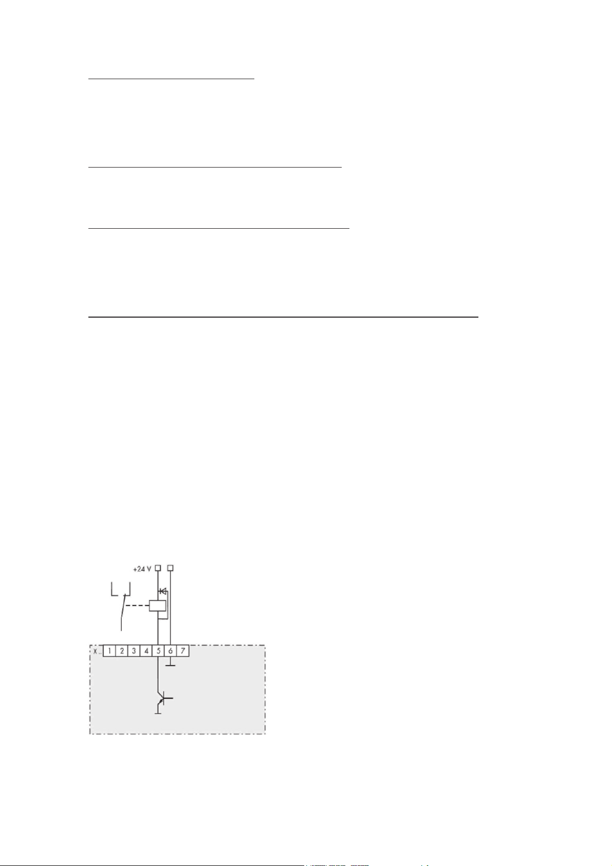
3.4 Freely addressable digital outputs
> As long as the terminals X1.5 to X8.5 of the bus module are not being used for switching over the set-
point, these can be used as switch outputs.
> Connect the relay to a 24 V DC coil voltage for free use. The idle circuit is integrated. The actuating
current is a maximum 120 mA per output. As a result it is possible to switch over, for example, the room
ventilators, anti-condensation heating, circuit breakers or control lamps via the bus.
Relais Control
10

4. Installation
DANGER
Dangers during Installation
Risk of injury / Risk of damage to the device or plant
Observe all safety regulations in the chapter “Safety”.
4.1 Connection terminals (overview)
Tab.1 Connecting terminals (overview)
Terminal Description
X11 .1 24V (+)
.2 24V (ground)
.3 grounding, carry out as short as possible
X1 - X8 .1 jointly switchable ground potential
.2 RxD
.3 TxD
.4 ground
.5 separately switchable ground potential
.6 ground
.7 ground potential for shield connection
Connection diagram see page 30.
4.2 Connecting a 24 V power supply
> Switch off the main power supply including the external 24 V power source and make sure these cannot
be accidentally switched back on again.
> Connect the external 24 V voltage supply (150 mA) to X11.1 (+) and X11.2 (-) (reverse polarity protec-
tion).
> Ground the X11.3 terminal by as short a route as possible (for EMC reasons).
REMARK
24 V DC power source
Several bus modules can be operated with one power supply.
> In cases of SELV (safety extra low voltages) do not ground the 24 V power source.
4.3 Connecting the power controller to X1-X8
> Switch off the main power supply including the external 24 V power source and make sure these cannot
be accidentally switched back on again.
> Connect the interfaces X1 to X8 of the bus module to the system interfaces of the power controller
(shielded four-wire cable)
Attention: To control all parameters by ProfiNet we recommend closing the Thyro-A switches S1.3, S1.4,
S1.5 (Thyro-Tool Mode).
4.4 Connecting the Ethernet bus module to the master
The Ethernet bus module has two Ethernet ports which are equipped with a switch functionality which
allows a line topology to be constructed.
A standard patch cable is required for connecting with a switch. For a direct connection (line topology) a
cross-over cable is required.
11
5. Settings
5.1 Setting the protocol
The Ethernet bus module supports various real time Ethernet bus systems. The desired system can be
selected using the rotary switch “Protocol”. For ProfiNet this needs to be set to 0.
5.2 Setting the number of slots
The number of devices which are connected to the Ethernet bus module is set with the rotary switch
“Slots”. After switching on, the Ethernet bus module reads all the parameters of the device. Following this
it starts communicating.
Attention: To change the number of slots when switched on, the switch “Slots” must first be turned to 0.
Communication with the master is then interrupted. Following this the desired number can be set. After
leaving the position 0 you have about 2 seconds time for this.
5.3 Setting the device name
Every IO device is identified by its device name. The setting of the device name can be undertaken using,
for example, the program “Step 7 – HW Config” in the menu “Target system / Ethernet / Edit Ethernet
participant…”
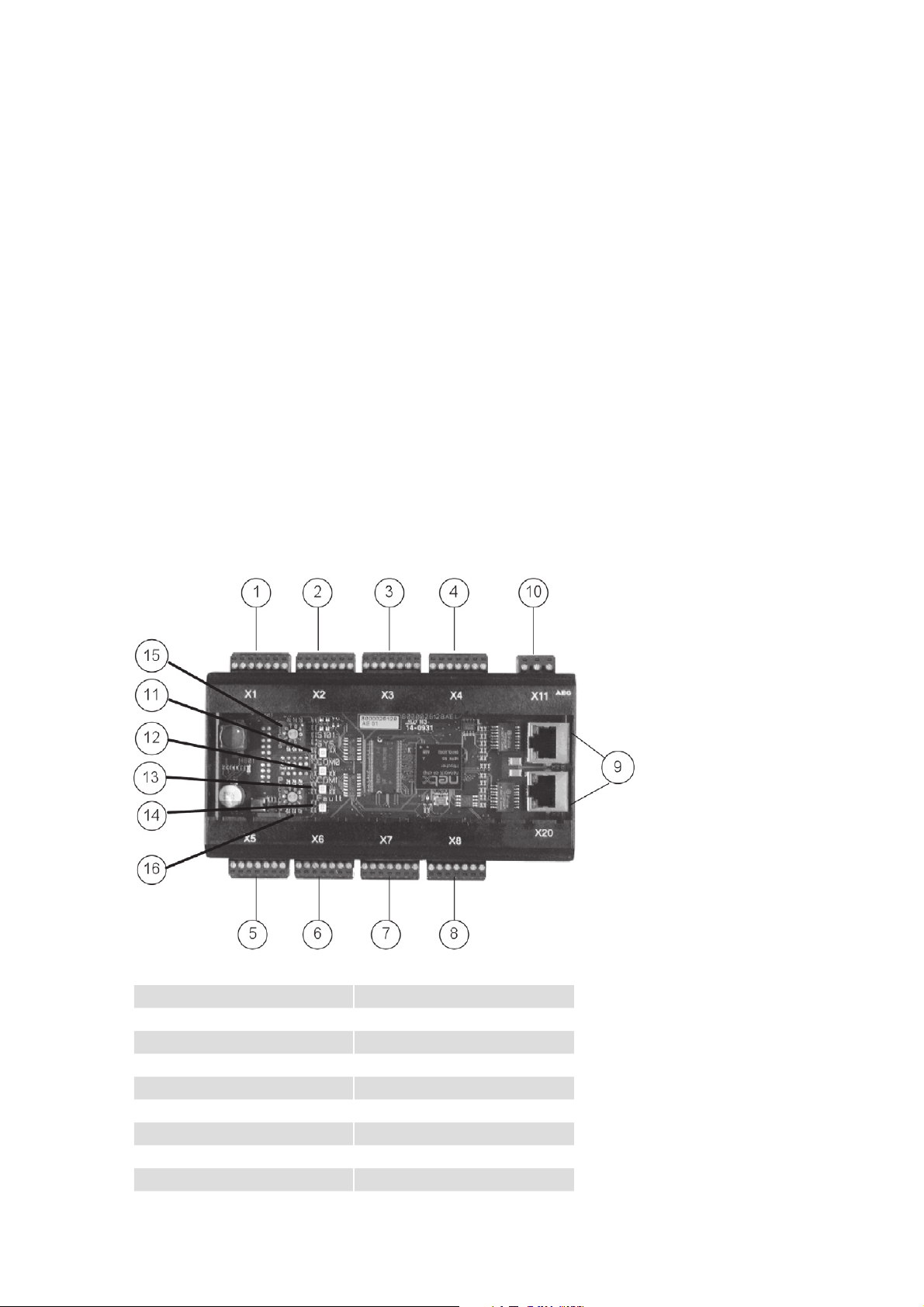
Fig. 1 Configuration & LED displays
1 Terminal X1 10 Terminal X11
2 Terminal X2 11 SYS LED
3 Terminal X3 12 COM0 (BF) LED
4 Terminal X4 13 COM1 (SF) LED
5 Terminal X5 14 Fault LED
6 Terminal X6 15 Switch Slots
7 Terminal X7 16 Switch Protocol
8 Terminal X8
9 Ethernet Port
12

5.4 Operating display of the bus module
Table 2 Operating display of the bus module
LED Color Status Meaning
SYS Green On Operating system running
Red Flashing with 1Hz Error in boot process
Red On Waiting for boot process (check position of
Off No supply voltage
COM0 (BF) Red On No physical connection
Red Flashing with 2Hz No data exchange
Off The device is exchanging data with the ProfiNet IO
COM1 (SF) Red On Watchdog time out or system error
Off No error
Fault Red On Hardware error
Operating status of the Ethernet bus module
“Protocol” switch)
Controller
LED Color Status Meaning
Link Green On There is an Ethernet connection
Activity Yellow On Data are being exchanged via Ethernet
Status LED of the Ethernet Ports
13

6. Operation
6.1 Start configuration (parameterization)
Via the parameterization (in step 7 – HW Config, double-click on slot 0 of the bus module, parameter tab)
the following settings can be undertaken.
No connection (slot 1-8):
Here you can set what should happen with the output data of the devices if the connection to the master
is interrupted.
Hold last values The output data are not changed.
Outputs = 0 The output data are set to 0
No connection (slot 9):
Here you can set what should happen with the output data of the bus module if the connection to the
master is interrupted.
Hold last value The digital outputs are not changed.
Outputs = 0 The digital outputs are set to 0.
Averaging of the measured values:
Here you can enter the number of actual values which flow into the averaging. A new value is calculated
once a second. Values from 0-20 can be entered, whereby 0 or 1 deactivates this function.
Remove device when it is switched off:
Not all devices are equipped with a 24 V supply connection. When switching off the Thyro mains supply
and the control voltage supply (24V) the Thyro no longer communicates with the bus modules. A switched
off device will normally be displayed as pull. This display can be suppressed here.
Deactivate Devices which are no longer accessible (no communication) will continue to
be displayed as plug.
Activate Devices which are no longer accessible will be displayed as pull.
Use output data:
The suppression of certain output data can be activated here.
Always New output data are transferred immediately.
Only when Bit is set New output data are only transferred, if the Bit 0 is set in the output
“Functions”
6.2 Cyclical data transmission (configuration)
The configuration of the cyclical data traffic is undertaken by adding modules.
The input and output data depend on the device types. The following tables show the input and output
data available for each of the devices.
6.3 Input and output data Thyro-S
With the Thyro-S the setpoint is interpreted as operating mode.
14

Tab. 3 Interpretation of the master setpoint with Thyro-S
Setpoint (Master) Status (return value) (Total setpoint)
0 to 409 = OFF 0 =
410 to 1091 1/5 819
1092 to 1706 = 1/3 1365 =
1707 to 3071 1/2 2047
3072 to 4096 = ON 4096
Tab. 4 Cyclic input and output data with Thyro-S ..H1
Offset Input data, actual values Data type Size Unit
0 Load voltage L1 float 4 [V]
4 Mains voltage L1 integer 2 [V]
6 Total setpoint integer 2 4096=100%
8 Fault (see table 5b) integer 2 -
10 Status (see table 5b) integer 2 -
Offset Output data, setpoint Data type Size Unit
0 Master Setpoint integer 2 4096=100%
Tab. 5 Cyclic input and output data with Thyro-S ..HRL1
Offset Input data, actual values Data type Size Unit
0 Load voltage L1 float 4 [V]
4 Load current L1 float 4 [A]
8 Mains voltage L1 integer 2 [V]
10 Total setpoint integer 2 4096=100%
12 Fault (see table 5b) integer 2 -
14 Status (see table 5b) integer 2 -
Offset Output data, setpoint Data type Size Unit
0 Master setpoint integer 2 4096=100%
Tab. 5b Thyro-S Faults
Description Bit LEDs Relay
Frequency measurement outside of 47 Hz to 63 Hz Bit 0 Test LED flashing slowly open
SYNC error, no zero-crossing within the gate Bit 1 Test LED flashing slowly open
Temperature monitoring triggered Bit 2 Load Fault flashing slowly open
Load fault Bit 3 Load Fault on open
Flash values invalid Bit 4 Test LED and Load Fault LED
flashing simultaneously quickly
Mains undervoltage (<AD_P_SPG_MIN) Bit 5 Load Fault LED and Test LED on open
Mains overvoltage (>AD_P_SPG_MAX) Bit 6 None closed
open
15

Tab. 5b Thyro-S Status
Description Bit LEDs Relay
Pulse inhib active Bit 0 none open
(bridge X2.1-X2.2 open) Bit 0 none open
Mains frequency is 60Hz Bit 2 none open
Relay status Bit 8 none open
(0=relay off / 1=relay on) Bit 8 none open
Device switched off Bit 9 -- closed
Wrong device Bit 10 -- ----
Bus module active
(0=no bus module / 1=bus module active)
Thyristor short-circuit Bit 14 Test LED and Load Fault LED
6.4 Input and output data Thyro-A
Tab. 6 Cyclic input and output data with Thyro-A 1A...H1
Offset Input data, actual values Data type Size Unit
0 Load voltage L1 float 4 [V]
4 Mains voltage L1 integer 2 [V]
6 Switch-on time TS integer 2 [period]
8 Switch-on angle alpha integer 2 [0.01 °el]
10 Total setpoint integer 2 4096=100%
12 Fault (see table 14b) integer 2 -
14 Status (see table 14b) integer 2 -
Offset Output data, setpoint Data type Size Unit
0 Master setpoint integer 2 4096=100%
Bit 11 none ----
----
flashing alternately slowly
Tab. 7 Cyclic input and output data with Thyro-A 1A...HRL1
Offset Input data, actual values Data type Size Unit
0 Load voltage L1 float 4 [V]
4 Load current L1 float 4 [A]
8 Mains voltage L1 integer 2 [V]
10 Switch-on time TS integer 2 [period]
12 Switch-on angle alpha integer 2 [0.01 °el]
14 Total setpoint integer 2 4096=100%
16 Fault (see table 14b) integer 2 -
18 Status (see table 14b) integer 2 -
Offset Output data, setpoint Data type Size Unit
0 Master setpoint integer 2 4096=100%
16

Tab. 8 Cyclic input and output data with Thyro-A 1A...HRLP1
Offset Input data, actual values Data type Size Unit
0 Load voltage L1 float 4 [V]
4 Load current L1 float 4 [A]
8 Power L1 float 4 [W]
12 Mains voltage L1 integer 2 [V]
14 Switch-on time TS integer 2 [period]
16 Switch-on angle alpha integer 2 [0.01 °el]
18 Total setpoint integer 2 4096=100%
20 Fault (see table 14b) integer 2 -
22 Status (see table 14b) integer 2 -
Offset Output data, setpoint Data type Size Unit
0 Master setpoint integer 2 4096=100%
Tab. 9 Cyclic input and output data with Thyro-A 2A...H1
Offset Input data, actual values Data type Size Unit
0 Load voltage L1 float 4 [V]
4 Load voltage L3 float 4 [V]
8 Mains voltage L1 integer 2 [V]
10 Mains voltage L3 integer 2 [V]
12 Switch-on time TS integer 2 [period]
14 Total setpoint integer 2 4096=100%
16 Fault (see table 14b) integer 2 -
18 Status (see table 14b) integer 2 -
Offset Output data, setpoint Data type Size Unit
0 Master setpoint integer 2 4096=100%
Tab. 10 Cyclic input and output data with Thyro-A 2A...HRL1
Offset Input data, actual values Data type Size Unit
0 Load voltage L1 float 4 [V]
4 Load voltage L3 float 4 [V]
8 Load current L1 float 4 [A]
12 Load current L2 float 4 [A]
16 Load current L3 float 4 [A]
20 Mains voltage L1 integer 2 [V]
22 Mains voltage L3 integer 2 [V]
24 Switch-on time TS integer 2 [period]
26 Total setpoint integer 2 4096=100%
28 Fault (see table 14b) integer 2 -
30 Status (see table 14b) integer 2 -
Offset Output data, setpoint Data type Size Unit
0 Master setpoint integer 2 4096=100%
17

Tab. 11 Cyclic input and output data with Thyro-A 2A...HRLP1
Offset Input data, actual values Data type Size Unit
0 Load voltage L1 float 4 [V]
4 Load voltage L3 float 4 [V]
8 Load current L1 float 4 [A]
12 Load current L2 float 4 [A]
16 Load current L3 float 4 [A]
20 Power L1 float 4 [W]
24 Power L3 float 4 [W]
28 Total power float 4 [W]
32 Mains voltage L1 integer 2 [V]
34 Mains voltage L3 integer 2 [V]
36 Switch-on time TS integer 2 [period]
38 Total setpoint integer 2 4096=100%
40 Fault (see table 14b) integer 2 -
42 Status (see table 14b) integer 2 -
Offset Output data, setpoint Data type Size Unit
0 Master setpoint integer 2 4096=100%
Tab. 12 Cyclic input and output data with Thyro-A 3A...H1
Offset Input data, actual values Data type Size Unit
0 Load voltage L1 float 4 [V]
4 Load voltage L2 float 4 [V]
8 Load voltage L3 float 4 [V]
12 Mains voltage L1 integer 2 [V]
14 Mains voltage L2 integer 2 [V]
16 Mains voltage L3 integer 2 [V]
18 Switch-on time TS integer 2 [period]
20 Switch-on angle alpha integer 2 [0.01 °el]
22 Total setpoint integer 2 4096=100%
24 Fault (see table 14b) integer 2 -
26 Status (see table 14b) integer 2 -
Offset Output data, setpoint Data type Size Unit
0 Master setpoint integer 2 4096=100%
18

Tab. 13 Cyclic input and output data with Thyro-A 3A...HRL1
Offset Input data, actual values Data type Size Unit
0 Load voltage L1 float 4 [V]
4 Load voltage L2 float 4 [V]
8 Load voltage L3 float 4 [V]
12 Load current L1 float 4 [A]
16 Load current L2 float 4 [A]
20 Load current L3 float 4 [A]
24 Mains voltage L1 integer 2 [V]
26 Mains voltage L2 integer 2 [V]
28 Mains voltage L3 integer 2 [V]
30 Switch-on time TS integer 2 [period]
32 Switch-on angle alpha integer 2 [0.01 °el]
34 Total setpoint integer 2 4096=100%
36 Fault (see table 14b) integer 2 -
38 Status (see table 14b) integer 2 -
Offset Output data, setpoint Data type Size Unit
0 Master setpoint integer 2 4096=100%
Tab. 14 Cyclic input and output data with Thyro-A 3A...HRLP1
Offset Input data, actual values Data type Size Unit
0 Load voltage L1 float 4 [V]
4 Load voltage L2 float 4 [V]
8 Load voltage L3 float 4 [V]
12 Load current L1 float 4 [A]
16 Load current L2 float 4 [A]
20 Load current L3 float 4 [A]
24 Power L1 float 4 [W]
28 Power L2 float 4 [W]
32 Power L3 float 4 [W]
36 Total power float 4 [W]
40 Mains voltage L1 integer 2 [V]
42 Mains voltage L2 integer 2 [V]
44 Mains voltage L3 integer 2 [V]
46 Switch-on time TS integer 2 [period]
48 Switch-on angle alpha integer 2 [0.01 °el]
50 Total setpoint integer 2 4096=100%
52 Fault (see table 14b) integer 2 -
54 Status (see table 14b) integer 2 -
Offset Output data, setpoint Data type Size Unit
0 Master setpoint integer 2 4096=100%
19

Tab. 14a Thyro-A Fault
Description Bit LEDs Relay
Frequency measurement outside of 47Hz to 63Hz Bit 0 Pulse Inhibit LED flashing slowly open
SYNC error, no cero crossing within the gate Bit 1 Pulse Inhibit LED flashing slowly open
Temperature monitoring triggered Bit 2 Load Fault LED flashing slowly open
Load fault Bit 3 Load fault LED on open
Flash values invalid Bit 4 Pulse Inhibit LED and Load
Fault LED flashing simultaneously qickly
Mains undervoltage (<AD_P_SPG_MIN) Bit 5 Pulse Inhibit LED, Load Fault
LED and test LED on
Mains overvoltage (>AD_P_SPG_MAX) Bit 6 none open
Master / slave fault (only with2A) Bit 8 none closed
Undervoltage limit Bit 9 none closed
Overvoltage limit Bit 10 none closed
Undercurrent limit Bit 11 none closed
Overcurrent limit Bit 12 none closed
Low power limit Bit 13 none closed
High power limit Bit 14 none closed
open
open
Tab. 14b Thyro-A Status
Description Bit LEDs Relay
Pulse inhib active (bridge X2.1-X2.2 open) Bit 0 Pulse Inhibit LED on closed
Mains frequency is 60Hz Bit 2 none closed
U-limiting Bit 4 Pulse Inhibit LED and Load
Fault LED flashing alternately
slowly
I-limiting Bit 5 Pulse Inhibit LED and Load
Fault LED flashing alternately
slowly
P-limiting Bit 6 Pulse Inhibit LED and Load
Fault LED flashing alternately
slowly
Relay status Bit 8 none on/off
(0=relay off / 1=relay on) Bit 8 none on/off
Device switched off Bit 9 -- --
Wrong device Bit 10 -- --
Bus module active
(0=no bus module / 1=bus module active)
Thyristor short-circuit Bit 14 only with Thyro-S ----
Failure rotating field / phase Bit 15 none closed
(only Thyro 2A or 3A) Bit 15 Pulse Inhibit LED and Test LED
Overcurrent limit Bit 12 none closed
Low power limit Bit 13 none closed
High power limit Bit 14 none closed
Bit 11 only with Thyro-S -----
flashing simultaneously slowly
closed
closed
closed
closed
20

Tab. 15 Cyclic input and output data with Thyro-A 1A...C01
Offset Input data, actual values Data type Size Unit
0 Load voltage L1 float 4 [V]
4 Load current L1 float 4 [A]
8 Power L1 float 4 [W]
12 Mains voltage L1 integer 2 [V]
14 Switch-on time TS integer 2 [period]
16 Switch-on angle alpha integer 2 [0.01 °el]
18 Total setpoint integer 2 4096=100%
20 Fault (see table 14b) integer 2 -
22 Status (see table 14b) integer 2 -
Offset Output data, setpoint Data type Size Unit
0 Master setpoint integer 2 4096=100%
Tab. 16 Cyclic input and output data with Thyro-A 1A...C02
Offset Input data, actual values Data type Size Unit
0 Load voltage phase 1 float 4 [V]
4 Load current phase 1 float 4 [A]
8 Load current phase 2 float 4 [A]
12 Total load current float 4 [A]
16 Mains voltage L1 integer 2 [V]
18 Switch-on angle alpha phase 1 integer 2 [0.01 °el]
20 Total setpoint integer 2 4096=100%
22 Fault (see table 14b) integer 2 -
24 Status (see table 14b) integer 2 -
Offset Output data, setpoint Data type Size Unit
0 Master setpoint integer 2 4096=100%
Tab. 17 Cyclic input and output data with Thyro-A 1A...C03
Offset Input data, actual values Data type Size Unit
0 Load voltage L1 float 4 [V]
4 Load current L1 float 4 [A]
8 Power L1 float 4 [W]
12 Mains voltage L1 integer 2 [V]
14 Switch-on time TS integer 2 [period]
16 Switch-on angle alpha integer 2 [0.01 °el]
18 Total setpoint integer 2 4096=100%
20 Fault (see table 14b) integer 2 -
22 Status (see table 14b) integer 2 -
Offset Output data, setpoint values Data type Size Unit
0 Master setpoint integer 2 4096=100%
21

Tab. 18 Cyclic input and output data with Thyro-A 1A...C05
Offset Input data, actual values Data type Size Unit
0 Load voltage phase 1 float 4 [V]
4 Load current phase 1 float 4 [A]
8 Load current phase 2 float 4 [A]
12 Total load current float 4 [A]
16 Power phase 1 float 4 [W]
20 Power phase 2 float 4 [W]
24 Total power float 4 [W]
28 Mains voltage L1 integer 2 [V]
30 Switch-on angle alpha phase 1 integer 2 [0.01 °el]
32 Total setpoint integer 2 4096=100%
34 Fault (see table 14b) integer 2 -
36 Status (see table 14b) integer 2 -
Offset Output data, setpoint Data type Size Unit
0 Master setpoint integer 2 4096=100%
Tab. 19 Cyclic input and output data with Thyro-A 1A...C07
Offset Input data, actual values Data type Size Unit
0 Load voltage L1 float 4 [V]
4 Load current L1 float 4 [A]
8 Power L1 float 4 [W]
12 Mains voltage L1 integer 2 [V]
14 Load temperature integer 2 [°C]
16 Switch-on angle alpha integer 2 [0.01 °el]
18 Total setpoint integer 2 4096=100%
20 Fault (see table 14b) integer 2 -
22 Status (see table 14b) integer 2 -
Offset Output data, setpoint Data type Size Unit
0 Master setpoint integer 2 4096=100%
Supported operating modes TPM; TSC; TMU
With the Thyro-Power Manager, Thyro-Step Controller and Thyro-Measurement Unit the input and output
data are depend on the operating mode. The following table shows which operating mode the devices
support.
Tab. 20 Supported operating modes
TPM TSC TIO TMU
automatic manual
Thyro-Power Manager X XXXX
Thyro-Step Controller - - X X X
Thyro-Measurement Unit - - - X X
22

6.5 Input and output data Thyro-Power Manager
Tab. 21 Cyclic input and output data TPM automatic mode
Offset Input data, actual values Data type Size Unit
0 AC input 1 float 4 [A],[V]
4 AC input 2 float 4 [A],[V]
8 AC input 3 float 4 [A],[V]
12 Power float 4 [W]
16 Energy float 4 [kWh]
20 DC input 1 integer 2 4096=100%
22 DC input 2 integer 2 4096=100%
24 DC input 3 integer 2 4096=100%
26 Mains voltage integer 2 [V]
28 Period duration integer 2 [μs]
30 Temperature integer 2 [°C]
32 Fault (see table 25b) integer 2 -
34 Status (see table 25b) integer 2 -
Tab. 22 Cyclic input and output data TPM manual mode
Offset Input data, actual values Data type Size Unit
0 AC input 1 float 4 [A],[V]
4 AC input 2 float 4 [A],[V]
8 AC input 3 float 4 [A],[V]
12 Power float 4 [W]
16 Energy float 4 [kWh]
20 DC input 1 integer 2 4096=100%
22 DC input 2 integer 2 4096=100%
24 DC input 3 integer 2 4096=100%
26 Mains voltage integer 2 [V]
28 Period duration integer 2 [μs]
30 Temperature integer 2 [°C]
32 Fault (see table 25b) integer 2 -
34 Status (see table 25b) integer 2 -
23

6.6 Input and output data Thyro-Step Controller
Tab. 23 Cyclic input and output data TSC mode
Offset Input data, actual values Data type Size Unit
0 AC input 1 float 4 [A],[V]
4 AC input 2 float 4 [A],[V]
8 AC input 3 float 4 [A],[V]
12 Power float 4 [W]
16 Energy float 4 [kWh]
20 DC input 1 integer 2 4096=100%
22 DC input 2 integer 2 4096=100%
24 DC input 3 integer 2 4096=100%
26 Mains voltage integer 2 [V]
28 Period duration integer 2 [μs]
30 Temperature integer 2 [°C]
32 Fault (see table 25b) integer 2 -
34 Status (see table 25b) integer 2 -
36 Analog output 4 integer 2 4096=100%
38 Steps integer 2 -
40 Total setpoint Integer 2 4096=100%
Offset Output data, setpoint Data type Size Unit
0 Master setpoint integer 2 4096=100%
6.7 Input and output data Thyro Input/Output Unit
Tab. 24 Cyclic input and output data TIO mode
Offset Input data, actual values Data type Size Unit
0 AC input 1 float 4 [A],[V]
4 AC input 2 float 4 [A],[V]
8 AC input 3 float 4 [A],[V]
12 Power float 4 [W]
16 Energy float 4 [kWh]
20 DC input 1 integer 2 4096=100%
22 DC input 2 integer 2 4096=100%
24 DC input 3 integer 2 4096=100%
26 Mains voltage integer 2 [V]
28 Period duration integer 2 [μs]
30 Temperature integer 2 [°C]
32 Fault (see table 25b) integer 2 -
34 Status (see table 25b) integer 2 -
Offset Output data, setpoint Data type Size Unit
0 Digital output integer 2 -
2 Analog output 1 integer 2 4096=100%
4 Analog output 2 integer 2 4096=100%
6 Analog output 3 integer 2 4096=100%
8 Analog output 4 integer 2 4096=100%
10 Analog output 5 integer 2 4096=100%
12 Analog output 6 integer 2 4096=100%
24

6.8 Input and output data Thyro-Measurement Unit
Tab. 25 Cyclic input and output data TMU mode
Offset Input data, actual values Data type Size Unit
0 AC input 1 float 4 [A],[V]
4 AC input 2 float 4 [A],[V]
8 AC input 3 float 4 [A],[V]
12 Power float 4 [W]
16 Energy float 4 [kWh]
20 DC input 1 integer 2 4096=100%
22 DC input 2 integer 2 4096=100%
24 DC input 3 integer 2 4096=100%
26 Mains voltage integer 2 [V]
28 Period duration integer 2 [μs]
30 Temperature integer 2 [°C]
32 Fault (see table 25b) integer 2 -
34 Status (see table 25b) integer 2 -
Tab. 25b Status TPM, TSC, TIO, TMU
Description Bit Fault LED, fault output*
Frequency measurement outside of 47Hz to 63Hz Bit 0 on
SYNC error, no cero crossing within the gate Bit 1 on
Temperature max. limit has been exceeded Bit 2 on
Temperature min. limit has been exceeded Bit 3 on
One or more parameters outside the limits Bit 4 on
Mains voltage lower than lower voltage limit Bit 5 on
Tab. 25b Fault TPM, TSC, TIO, TMU
Description Bit Alarm LED, alarm output*
Mains frequency is 60Hz Bit 2 off
Transformer 1 fallen below min. limit Bit 3 on
Transformer 1 exceeded max. limit Bit 4 on
Transformer 2 fallen below min. limit Bit 5 on
Transformer 2 exceeded max. limit Bit 6 on
Transformer 3 fallen below min. limit Bit 7 on
Transformer 3 exceeded max. limit Bit 8 on
Device switched off Bit 9 --
Wrong device Bit 10 --
Bus module active (0=no bus module / 1=bus module
active)
Bit 11 off
* Default setting can be parameterized.
25

6.9 Acyclic data transmission (parameterization)
Via the acyclic parameter data transmission, parameters of the devices can be changed or selected.
Cyclical and acyclical services can be used in the network simultaneously.
Read data record “RDREC”:
For reading access to a data record, the slot, index and length of the data record must be entered. At step
7 and when using the SFB 52 the Logical Address of the slot is to be entered instead of the slot. As such
the device at slot X1 is to be activated as the device at slot 1.
Error code Meaning
DE80B000 The unit does not recognize the parameter (invalid index)
DE80B100 The length entry of the parameter is incorrect
DE80B200 The projected slot is not occupied
DE80B300 The actual unit type does not match the set unit type
Write data record “WRREC”:
For writing access to a data record, the slot, index, length of the data record and the new value must be
entered. At step 7 and when using the SFB 53 the Logical Address of the slot is to be entered instead of
the slot.
Error code Meaning
DF80B000 The unit does not recognize the parameter (invalid index)
DF80B100 The length entry of the parameter is incorrect
DF80B200 The projected slot is not occupied
DF80B300 The actual unit type does not match the set unit type
DF80B600 The parameter cannot be changed
DF80B700 Invalid range of values of a parameter
You will find the parameter tables (acyclic) of each of the device types in Appendix 17 (A).
26

7. External connections
7.1 Power supply
+24V to X11, current consumption approx. 150mA
bridge (contact)
Thyro-S: see chapter 3.1
Thyro-a: see chapter 3.2
TPM: see chapter 3.3
X1 - X8 to the power controllers
supply
24V DC (approx. 150mA)
The foregoing circuit diagram shows the connection of the bus module
27

7.2 Operating elements and terminal blocks
This chapter describes the available terminal blocks, plug connectors and operating elements.
Configuration of the 7 pin connector of slots X1 to X8:
1 Switched ground potential. All pins 1 of slots X1 – X8 are connected.
2 RxD
3 TxD
4 Ground
5 Switchable ground potential. The slots X1 – X8 can be switched as desired.
6 Ground
7 Ground potential for shield connection
Configuration of the 3 pin connector X11:
X11: +24V
X11: 24V - ground
X11: Grounding, carry out by as short a route as possible.
28

8. Interfaces
8.1 System interface
The bus module is connected with the relevant system interfaces of the power controllers via X1 to X8
(four-wire, 2x2 twisted, shared shielding).
The transmission rate is 38,400 Bd.
The asynchronous characters are transferred with 8bit, no parity, one stop bit. The protocol begins with
STX, followed by an identifier, the data, and is concluded with a check sum. Defective protocols are
ignored.
8.2 Ethernet interfaces
Communication medium CAT 5e
Network topology tree, star and line
Maximum cable length 100m
ProfiNET-participants restricted to the maximum supported number of devices by the con-
troller used
PNO identification number0x0188
Device ID 0x0001
Transmission rate 100 Mbit/s
29

9. Connection diagrams Thyro-A
Fig. 2 Connection diagram Thyro-A
bus setpoint/
analog input
setpoint 1
bus setpoint is
active
bus setpoint/
analog input
setpoint 2
analog input is
active
setpoint
*blank
bus setpoint/
analog input
setpoint 8
group switching
bus setpoint/
analog input
setpoint 1
selective switching
bus setpoint/analog input
bus setpoint/
analog input
setpoint 2
bus setpoint/analog input
bus setpoint/
analog input
setpoint 8
30

10. Connection diagrams Thyro-S
Fig. 3 Connection diagram Thyro-S
bus setpoint/
analog input
setpoint 1
ON/OFF
bus setpoint is
active
bus setpoint/
analog input
setpoint 2
ON/OFF
analog input is
active
setpoint
*blank
bus setpoint/
analog input
setpoint 8
ON/OFF
group switching
bus setpoint/
analog input
setpoint 1
ON/OFF
selective switching
bus setpoint/analog input
bus setpoint/
analog input
setpoint 2
ON/OFF
bus setpoint/analog input
bus setpoint/
analog input
setpoint 8
ON/OFF
31
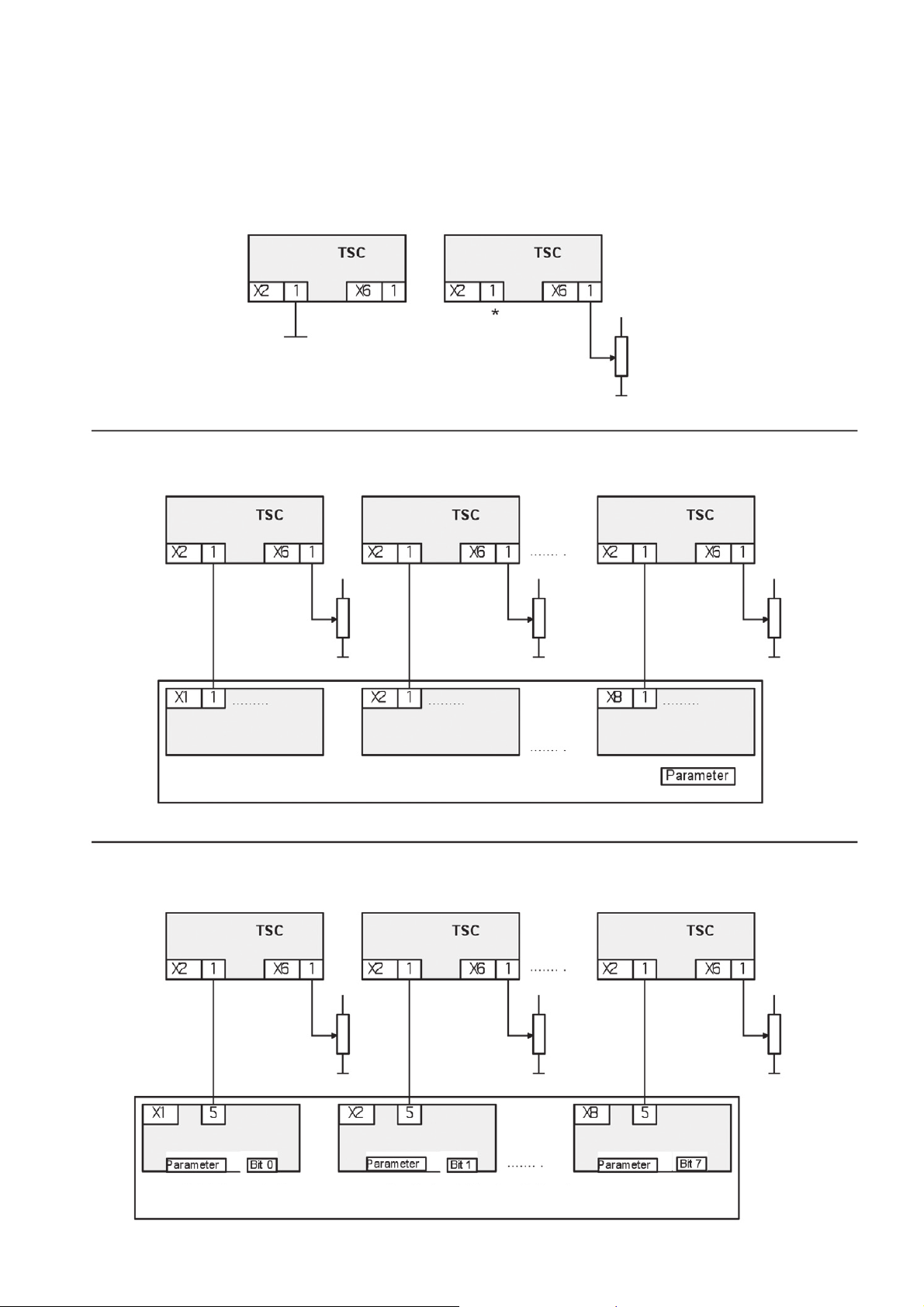
11. Connection diagrams TSC
Fig. 4 Connection diagram TSC
bus setpoint/
analog input
setpoint 1 setpoint 2 setpoint 8
bus setpoint is
active
bus setpoint/
analog input
analog input is
active
setpoint
*blank
bus setpoint/
analog input
group switching
bus setpoint/
analog input
setpoint 1 setpoint 2 setpoint 8
selective switching
bus setpoint/analog input
bus setpoint/
analog input
bus setpoint/analog input
bus setpoint/
analog input
32

12. Specific notes
12.1 Installation
The bus modules can be installed in any desired order.
12.2 Service
The devices supplied have been produced in accordance with the quality standard ISO 9001. Should there
be faults in spite of this, our 24 hour service hotline is on hand, tel.: +49 (0)2902 763-100.
13. Technical Data
Power supply 24V DC 150mA
Connection options for up to 8 AEG power controllers of series Thyro-S, Thyro-A and the TPM
series
Function control LED
Assembly DIN rail
Ambient temperature maximum 55°C
Dimensions (WxDxH): 150 x 60 x 95 mm
Weight circa: 0.35 kg
33
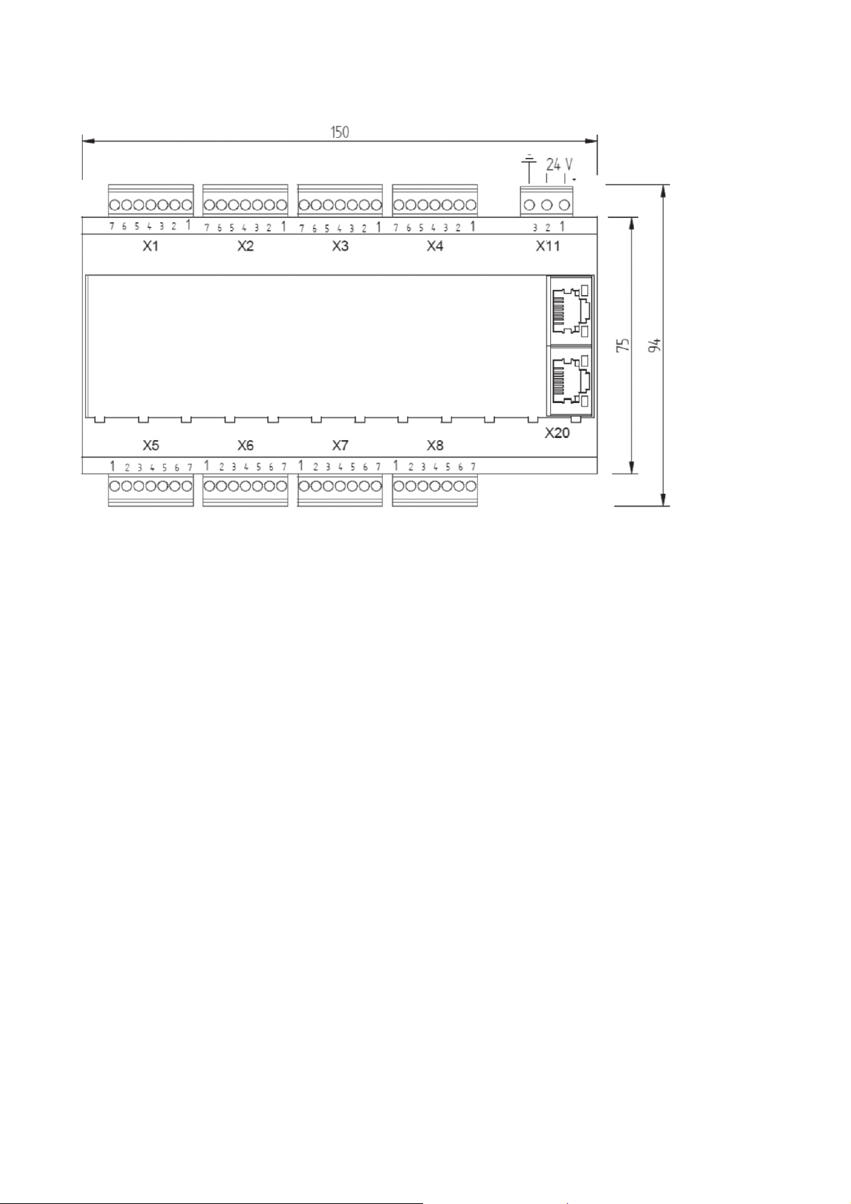
14. Dimension drawings
55 mm height
incl. cover
15. Accessories and options
Ready-made bus module-side shielded cable.
A set of cable consists of 4 connection cables for connecting 4 power controllers.
Order number 2000 000 848 Bus module connection cable for 4 controllers, 2.5 m long
Order number 2000 000 849 Bus module connection cable for 4 controllers, 1.5 m long
16. Approvals and conformity
- Quality standard in acc. with EN ISO 9001
- CE conformity
- ProfiNet conformity
- RoHS compliant 5/6
- Directives
The CE mark on the device confirms compliance with the EC directives 2006 / 95 / EEC for low voltage
and 2004 / 108 / EEC for electromagnetic compatibility if the instructions on installation and commissioning described in the operating instructions are followed.
34

In detail
ProfiNet IEC 61158
IEC 61784
Built-in device (VDE0160) EN 50 178
Storage temperature (D) -25°C - +55°C
Transport temperature -25°C - +70°C
Operating temperature (better B) -10°C - +55°C
Humidity class B EN 50 178 tab. 7 (EN 60 721)
Degree of contamination 2 EN 50 178 tab. 2
Air pressure 900mbar * 1000m above sea level
Degree of protection IP00 EN 69 529
EMC-testing EN 61000-6-2 (-4)
Emitted interference CISPR 16
Radiated immunity EN/IEC 61000-4-3
Conducted immunity EN/IEC 61000-4-6
ESD 8kV (A) EN/IEC 61000-4-2
Burst control lines 1kV (A) EN 61000-4-4
35

17. Appendix A
1. Acyclic parameter table Thyro-S; Thyro-A; -C01; -C02; -C03; -C05
Table A: Thyro-S.., Thyro-A.., Thyro-A-C01; -C02; -C03; -C05 controller parameters slot 1-8
Controller parameter
Index Symbol Name Data type Value range Combo-opt.
1 I_TYP Controller type current u16 0…
2 U_TYP Controller supply voltage u16 0…1000
3 P_TYP Controller type output power u32 0…
6 BETR Operating mode u16 0…3 Reserved, TAKT, VAR, QTM
7 AN1 Phase angle of 1st half wave u16 0…180
8 SST Soft start duration (given) u16 0…1000
9 SDN Soft stop duration (given) u16 0…1000
10 T0 Cycle period duration u16 0…1000
11 MP Minimum interval u16 0…10
12 TSMAX Maximum cycle turn on time u16 1…T0
13 TSMIN Minimum cycle turn on time u16 0…T0
14 V_IE Front pulse stop u16 0…180
15 H_IE Back pulse stop u16 0…180
2, U
, I
2, I
16 RE Control (analog output value) u16 0…8 U
17 TI_1 PI controller, I part u16 0= aus 0…65535
18 KP_1 PI controller, P part u16 0= aus 0…65535
19 KR_1 PI controller, counter P part u16 0…65535
20 V_IE_2 Front pulse stop phase 2 u16 0…180
21 UEMA Effective voltage setpoint maximum u16 0…
22 IEMA Effective current setpoint maximum u16 0…
23 PMA Power setpoint maximum u32 0…
24 SW_ENABLE Setpoint activation u16 0…3 Bit0=1 setpoint x2.4 active, Bit1=1 setpoint
27 SW_REGLER Setpoint x2.4 u16 0…4096
28 OF_1 Actual value output offset 1 u16 0…4096
29 FA_1 Scale end value actual value output 1 u16 0…4096
30 SPG_MIN Mains voltage monitoring min. u16 0…1000
31 SPG_MAX Mains voltage monitoring max. u16 0…1000
32 UN_S Undercurrent monitoring u16 0…1 on, off
33 RELAIS_CTRL_2 Relay configuration 2 u16 0…65535 bit coded
34 LASTBRUCH_MIN_ABS Load fault, minimum value u16 0…4505
36 SYNC_ADR Synchro cycle address u16 0…65535
37 IMAB Pulse switch-off in case of failure u16 0…65535 bit coded
38 STA_RE Control start controller analog setpoint u16 0…65535
39 STE_RE Control end controller analog setpoint u16 0…65535
40 Configuration 3A u16 bit coded
41 MOSI_FA Peak current value limit u16 0…4096
42 DAC_1_CTRL Analog output configuration 1 u16 0…10
44 VERS_T Version day u16 1…31
45 VERS_M Version month u16 1…12
46 VERS_J Version year u16 0…9999
48 Controller inhibit u16 0…1 on, off
49 RELAIS_CTRL Relay configuration 1 u16 0…65535 bit coded
50 Save u16 0…1 off, save
56 MITTEL Averaging analog output 1 u16 0…65535
84 TEMP Temperature u16 -50…150
109 MITTEL_2 Averaging analog output 2 u16 0…65535
110 OF_2 Actual value output offset 2 u16 0…4096
111 FA_2 Scale end value actual value output 2 u16 0…4096
112 DAC_2_CTRL Analog output configuration 2 u16 0…10
115 MITTEL_3 Averaging analog output 3 u16 0…65535
116 OF_3 Actual value output offset 3 u16 0…4096
117 FA_3 Scale end value actual value output 3 u16 0…4096
118 DAC_3_CTRL Analog output configuration 3 u16 0…10
119 U_MIN Voltage limit minimum u16 0…65535
120 U_MAX Voltage limit maximum u16 0…65535
121 I_MIN Current limit minimum u16 0…65535
122 I_MAX Current limit maximum u16 0…65535
123 P_MIN Power limit minimum u32 0…
124 P_MAX Power limit maximum u32 0…
load
load eff
reserved, reserved, without regulation
master active
, reserved, real power,
load
load eff
36

1S 1A 2A 3A 1A
Unit R / W
H1
HRL1H1HRL1
A r x x x x x x x x x x x x x x x type 1
V r x x x x x x x x x x x x x x x type 2
W r x x x x x x type H RLP1 3
r/w * x x x x x x x x x x x x x TAKT S1.1-2 6
˚el r/w * x x x x x x x x x x x 60˚el R201 7
period r/w * x x x x x x x x x x x x x 6 period R201 8
period r/w x x x x x x x x x x x x x 6 period 9
period r/w* x x x x x x x x x x x 50 period R201 10
period r/w * x x x x x x x x x x x 3 period R201 11
period r/w x x x x x x x x x x x 50 period 12
period r/w x x x x x x x x x x x 0 period 13
˚el r/w xxx xxxxxxx180˚el 14
˚el r/w xxx xxxxxxx0˚el 15
r/w * x x x x x x x x x x x x x Uload² S1.3-5 power only with H RLP1 16
r/w xxxxxxxxxxxxx20 17
r/w xxxxxxxxxxxxx60 18
r/w xxxxxxxxxxxxx10 19
period r/w x x 20
0.1 V r/w * x x x x x x x x x x x x x 440V R 202 ** 21
0.1 A r/w * x x x x x x x x x x 110A R 203 22
W r/w * x x x x x x 0 R 202 ** 23
r xxxxxxxxxxxxxxx0 24
HRLPH1HRL1
HRLPH1HRL1
HRLP
C01
C02
Default Note Index
C03
C05
4096=100% r x x x x x x x x x x x x x x x 27
20/4096mA r/w * x x x x x x x x x x 0mA S1.9 28
1/819 r/w * x x x x x x x x x x 1 R 204 29
V r/w x x x x x x x x x x x x x x x type 30
V r/w x x x x x x x x x x x x x x x type 31
r/w * x x x x x x x x x x x off R 205 32
r/w xx xx xxxxxx0 33
100/4096% r/w * x x x x x x x x x x x 0% R 205 34
period /2 r/w x x x x x x x x x x x 100 36
r/w xxxxxxxxxxxxx0 37
20/4096mA r/w * x x x x x x x x x x x x x 0mA S1.6 38
20/4096mA r/w x x x x x x x x x x x x x 20mA 39
r/w x x x 40
r/w x x x x x x x x x x x x x type 41
r/w xx xx xxxxxx6 42
r xxxxxxxxxxxxxxx 44
r xxxxxxxxxxxxxxx 45
r xxxxxxxxxxxxxxx 46
r/w xxxxxxxxxxxxxxxoff 48
r/w x x x x x x x x x x 447 49
r/w xxxxxxxxxxxxxxxoff 50
r/w x x x x x x x x x x 100 56
°C r xxxxxxxxxxxxxxx 84
r/w x x 100 109
20/4096mA r/w x x 0mA S1.9 110
1/819 r/w x x 1 R 204 111
r/w x x 6 112
r/w x x 100 115
20/4096mA r/w x x 0mA S1.9 116
1/819 r/w x x 1 R 204 117
r/w x x 6 118
0.1 V r/w x x x x x x x x x x x 119
0.1 V r/w x x x x x x x x x x x 120
0.1 A r/w x x x x x x x x 121
0.1 A r/w x x x x x x x x 122
W r/w x x x x x 123
W r/w x x x x x 124
37

2. Acyclic parameter table Thyro-C07
Table B: Thyro-C07 controller parameters slot 1-8
Controller parameter
Symbol Name Data
Index
1 I_TYP Controller type current u16 0…
2 U_TYP Controller supply voltage u16 0…1000
3 P_TYP Controller type output power u32 0…
6 BETR Operating mode u16 0…3 reserved, TAKT, VAR, QTM
7 AN1 Phase angle of 1st half wave u16 0…180
8 SST u16 0…1000
9 SDN Soft stop duration (given) u16 0…1000
10 T0 Cycle period duration u16 0…1000
11 MP Minimum interval u16 0…10
12 TSMAX Maximum cycle turn on time u16 1…T0
13 TSMIN Minimum cycle turn on time u16 0…T0
14 V_IE Front pulse stop u16 0…180
15 H_IE Back pulse stop u16 0…180
16 RE Control (analog output value) u16 0…9 Uload2, Uload eff, Iload2, Iload eff, reserved, real power,
17 TI_1 PI controller, I part u16 0= aus
18 KP_1 PI controller, P part u16 0= aus
19 KR_1 PI controller, counter P part u16 0…65535
20 Temperature coefficient of the heating tape u16 0…65535
21 UEMA Effective voltage setpoint maximum u16 0…
22 IEMA Effective current setpoint maximum u16 0…
23 PMA Power setpoint maximum u32 0…
24 SW_ENABLE Setpoint activation u16 0…3 bit0=1 setpoint x2.4 active, bit1=1 setpoint master active
27 SW_REGLER Setpoint x2.4 u16 0…4096
28 OF_1 Actual value output offset 1 u16 0…4096
29 FA_1 Scale end value actual value output 1 u16 0…4096
30 SPG_MIN Mains voltage monitoring min. u16 0…1000
31 SPG_MAX Mains voltage monitoring max. u16 0…1000
32 UN_S Undercurrent monitoring u16 0…1 off, on
33 RELAIS_CTRL_2 Relay configuration 2 u16 0…65535 bit coded
34 LASTBRUCH_MIN_
ABS
36 SYNC_ADR Synchro cycle address u16 0…65535
37 IMAB Pulse switch-off in case of failure u16 0…65535 bit coded
38 STA_RE Control start controller analog setpoint u16 0…65535
39 STE_RE Control end controller analog setpoint u16 0…65535
41 MOSI_FA Peak current value limit u16 0…4096
42 DAC_1_CTRL Analog output configuration 1 u16 0…11
44 VERS_T Version day u16 1…31
45 VERS_M Version month u16 1…12
46 VERS_J Version year u16 0…9999
48 Controller inhibit u16 0…1 off, on
49 RELAIS_CTRL Relay configuration 1 u16 0…65535 bit coded
50 Save u16 0…1 off, save
56 MITTEL Averaging analog output 1 u16 0…65535
84 TEMP Temperature u16 -50…150
109 MITTEL_2 Averaging analog output 2 u16 0…65535
110 OF_2 Actual value output offset 2 u16 0…4096
111 FA_2 Scale end value actual value output 2 u16 0…4096
112 DAC_2_CTRL Analog output configuration 2 u16 0…11
115 MITTEL_3 Averaging analog output 3 u16 0…65535
116 OF_3 Actual value output offset 3 u16 0…4096
117 FA_3 Scale end value actual value output 3 u16 0…4096
118 DAC_3_CTRL Analog output configuration 3 u16 0…11
119 U_MIN Voltage limit minimum u16 0…65535
120 U_MAX Voltage limit maximum u16 0…65535
121 I_MIN Current limit minimum u16 0…65535
122 I_MAX Current limit maximum u16 0…65535
123 P_MIN Power limit minimum u32 0…
124 P_MAX Power limit maximum u32 0…
Load fault, minimum value u16 0…4505
type
Value
range
0…65535
0…65535
Combo-opt.
reserved, reserved, without regulation, temperature
38

unit R / W Default Note Index
A r type 1
V r type 2
W r type H RLP1 3
°el r/w * 60°el R201 7
period r/w 6 period 9
period r/w* 50 period R201 10
period r/w * 3 period R201 11
period r/w 50 period 12
period r/w 0 period 13
°el r/w 180°el 14
°el r/w 0°el 15
0.1V r/w * 440V R202** 21
0.1A r/w * 110A R203 22
W r/w * 0 R202** 23
4096=100% r 27
20/4096mA r/w * 0mA S1.9 28
1/819 r/w * 1 R204 29
V r/w type 30
V r/w type 31
100/4096% r/w * 0% R205 34
r/w * TAKT S1.1-2 6
r/w * 8
r/w * Uload2 S1.3-5 power only with
H RLP1
r/w 20 17
r/w 60 18
r/w 10 19
r/w 20
r0 24
r/w * off R205 32
r/w 0 33
16
period/2 r/w 100 36
20/4096mA r/w * 0mA S1.6 38
20/4096mA r/w 20mA 39
°C r 84
20/4096mA r/w 0mA S1.9 110
1/819 r/w 1 R204 111
20/4096mA r/w 0mA S1.9 116
1/819 r/w 1 R204 117
0.1V r/w 119
0.1V r/w 120
0.1A r/w 121
0.1A r/w 122
W r/w 123
W r/w 124
r/w 0 37
r/w type 41
r/w 6 42
r 44
r 45
r 46
r/w off 48
r/w 447 49
r/w off 50
r/w 100 56
r/w 100 109
r/w 6 112
r/w 100 115
r/w 6 118
39

3. Acyclic parameter table Thyro-Power Manager
Table C: TPM parameters slot 1-8
Controller parameter
Symbol Name Data
Index
1 W1_TYP Type value transformer 1 u16 1...65535
2 W2_TYP Type value transformer 2 u16 1...65535
3 W3_TYP Type value transformer 3 u16 1...65535
4 W_CTRL Transformer setting u16 0...65535 bit coded
5 U_TYP Type value U mains u16 1…260
7 T0 u16 1…1500
8 ANZ Number u16 2…10
9 T01 1st time / phase 1 u16 0…T0
10 T02 2nd time / phase 2 u16 0…T0
11 T03 3rd time / phase 3 u16 0…T0
12 T04 4th time / phase 4 u16 0…T0
13 T05 5th time / phase 5 u16 0…T0
14 T06 6th time / phase 6 u16 0…T0
15 T07 7th time / phase 7 u16 0…T0
16 T08 8th time / phase 8 u16 0…T0
17 T09 9th time / phase 9 u16 0…T0
18 T10 10th time / phase 10 u16 0…T0
39 DAC1_OF Offset 1 u16 0…4095
40 DAC1_FA Scale end value 1 u16 0…4096
41 DAC1_CTRL Output value 1 u16 1…16 transformer1, transformer2, transformer3, U mains, setpoint1,
42 DAC2_OF Offset 2 u16 0…4095
43 DAC2_FA Scale end value 2 u16 0…4096
44 DAC2_CTRL Output value 2 u16 1…16 transformer1, transformer2, transformer3, U mains, setpoint1,
45 DAC3_OF Offset 3 u16 0…4095
46 DAC3_FA Scale end value 3 u16 0…4096
47 DAC3_CTRL Output value 3 u16 1…16 transformer1, transformer2, transformer3, U mains, setpoint1,
48 DAC4_OF Offset 4 u16 0…4095
49 DAC4_FA Scale end value 4 u16 0…4096
50 DAC4_CTRL Output value 4 u16 1…16 transformer1, transformer2, transformer3, U mains, setpoint1,
51 DAC5_OF Offset 5 u16 0…4095
52 DAC5_FA Scale end value 5 u16 0…4096
53 DAC5_CTRL Output value 5 u16 1…16 transformer1, transformer2, transformer3, U mains, setpoint1,
54 DAC6_OF Offset 6 u16 0…4095
55 DAC6_FA Scale end value 6 u16 0…4096
56 DAC6_CTRL Output value 6 u16 1…16 transformer1, transformer2, transformer3, U mains, setpoint1,
57 DAC_MITTEL Average u16 1…65535
58 SPG_MIN Lower limit mains voltage u16 0…5120
59 SPG_MAX Upper limit mains voltage u16 0…5120
60 W1_MAX Limit transformer 1 u16 0…8192
61 W2_MAX Limit transformer 2 u16 0…8192
62 W3_MAX Limit transformer 3 u16 0…8192
63 WA_CTRL Monitoring mode transformer u16 0...65535 bit coded
64 Fault output u16 0...65535 bit coded
66 Alarm output u16 0...65535 bit coded
68 Vers_D Firmware version day u16 1…31
69 Vers_M Firmware version month u16 1…12
70 Vers_Y Firmware version year u16 0…9999
72 Save u16 0…1 off, save
74 Operating hours f32 0…
76 TEMP_MAX Limiting value temperature u16 0…255
99 Energy f32 0…
105 Analog output 1 u16 0…4096
106 Analog output 2 u16 0…4096
107 Analog output 3 u16 0…4096
108 Analog output 4 u16 0…4096
109 Analog output 5 u16 0…4096
110 Analog output 6 u16 0…4096
121 Device number u32 0…
123 Serial number u16 0…
124 PCB number u32 0…
126 F_MIN_MAX Frequency limit u16 100…2500
127 F_TOL Frequency tolerance u16 1…25
type
Value
range
Combo-opt.
setpoint2, R309, R310, temp., res., controller1,…, controller6
setpoint2, R309, R310, temp., res., controller1,…, controller6
setpoint2, R309, R310, temp., res., controller1,…, controller6
setpoint2, R309, R310, temp., res., controller1,…, controller6
setpoint2, R309, R310, temp., res., controller1,…, controller6
setpoint2, R309, R310, temp., res., controller1,…, controller6
40

Unit R / W Default Note Index
r/w 100 1
r/w 100 2
r/w 100 3
r/w 8 4
r/w 230 5
r/w * 50 R309 7
r/w * 10 S2 8
r/w 0 9
r/w 5 10
r/w 10 11
r/w 15 12
r/w 20 13
r/w 25 14
r/w 30 15
r/w 35 16
r/w 40 17
4096=10V r/w 0 39
1/819 r/w 819 40
4096=10V r/w 0 42
1/819 r/w 819 43
4096=10V r/w 0 45
1/819 r/w 819 46
r/w 45 18
r/w 1 41
r/w 2 44
r/w 3 47
4096=10V r/w 0 48
1/819 r/w 819 49
4096=10V r/w 0 51
1/819 r/w 819 52
4096=10V r/w 0 54
1/819 r/w 819 55
hr 74
°C r/w 80 76
kWh r 99
% r/w 9 127
r/w 4 50
r/w 9 53
r/w 16 56
r/w 100 57
r/w 3473 58
r/w 4541 59
r/w * 5118 R310 60
r/w * 5118 R310 61
r/w * 5118 R310 62
r/w 16399 63
r/w 127 64
r/w 504 66
r 68
r 69
r 70
r/w 0 72
r 105
r 106
r 107
r 108
r 109
r 110
r 121
r 123
r 124
r/w 1709 126
41

4. Acyclic parameter table Thyro-Step Controller
Table D: TSC parameters slot 1-8
Controller parameter
Symbol Name Data
Index
1 W1_TYP Type value transformer 1 u16 1...65535
2 W2_TYP Type value transformer 2 u16 1...65535
3 W3_TYP Type value transformer 3 u16 1...65535
4 W_CTRL Transformer setting u16 0...65535
5 U_TYP Type value U network u16 1…260 bit coded
7 T0 u16 1…1500
8 ANZ Number u16 1…11
9 S01 1st phase u16 1…32768
10 S02 2nd phase u16 1…32768
11 S03 3rd phase u16 1…32768
12 S04 4th phase u16 1…32768
13 S05 5th phase u16 1…32768
14 S06 6th phase u16 1…32768
15 S07 7th phase u16 1…32768
16 S08 8th phase u16 1…32768
17 S09 9th phase u16 1…32768
18 S10 10th phase u16 1…32768
27 Setpoint activation 1 u16 0…3 bit0=1 setpoint x6.1 active, bit1=1 setpoint master active
31 Control start setpoint 1 u16 0…4096
32 Control stop setpoint 1 u16 0…4096
37 Control start setpoint 2 u16 0…4096
38 Control stop setpoint 2 u16 0…4096
39 DAC1_OF Offset 1 u16 0…4095
40 DAC1_FA Scale end value 1 u16 0…4096
41 DAC1_CTRL Output value 1 u16 1…16 transformer1, transformer2, transformer3, U mains, setpoint1,
42 DAC2_OF Offset 2 u16 0…4095
43 DAC2_FA Scale end value 2 u16 0…4096
44 DAC2_CTRL Output value 2 u16 1…16 transformer1, transformer2, transformer3, U mains, setpoint1,
45 DAC3_OF Offset 3 u16 0…4095
46 DAC3_FA Scale end value 3 u16 0…4096
47 DAC3_CTRL Output value 3 u16 1…16 transformer1, transformer2, transformer3, U mains, setpoint1,
48 DAC4_OF Offset 4 u16 0…4095
49 DAC4_FA Scale end value 4 u16 0…4096
50 DAC4_CTRL Output value 4 u16 1…16 transformer1, transformer2, transformer3, U mains, setpoint1,
51 DAC5_OF Offset 5 u16 0…4095
type
Value range Combo-opt.
setpoint2, R309, R310, temp., res., controller1,…, controller6
setpoint2, R309, R310, temp., res., controller1,…, controller6
setpoint2, R309, R310, temp., res., controller1,…, controller6
setpoint2, R309, R310, temp., res., controller1,…, controller6
52 DAC5_FA Scale end value 5 u16 0…4096
53 DAC5_CTRL Output value 5 u16 1…16 transformer1, transformer2, transformer3, U mains, setpoint1,
54 DAC6_OF Offset 6 u16 0…4095
55 DAC6_FA Scale end value 6 u16 0…4096
56 DAC6_CTRL Output value 6 u16 1…16 transformer1, transformer2, transformer3, U mains, setpoint1,
57 DAC_MITTEL Average u16 1…65535
58 SPG_MIN Lower limit mains voltage u16 0…5120
59 SPG_MAX Upper limit mains voltage u16 0…5120
60 W1_MAX Limit transformer 1 u16 0…8192
61 W2_MAX Limit transformer 2 u16 0…8192
62 W3_MAX Limit transformer 3 u16 0…8192
63 WA_CTRL Monitoring mode transformer u16 0...65535 bit coded
64 Fault output u16 0...65535 bit coded
66 Alarm output u16 0...65535 bit coded
68 Vers_D Firmware version day u16 1…31
69 Vers_M Firmware version month u16 1…12
70 Vers_Y Firmware version year u16 0…9999
72 Save u16 0…1 off, save
74 Operating hours f32 0…
76 TEMP_MAX Limiting value temperature u16 0…255
99 Energy f32 0…
105 Analog output 1 u16 0…4096
106 Analog output 2 u16 0…4096
107 Analog output 3 u16 0…4096
108 Analog output 4 u16 0…4096
109 Analog output 5 u16 0…4096
110 Analog output 6 u16 0…4096
119 DC input 3 (x5.10) u16 0…4096
121 Device number u32 0…
123 Serial number u16 0…
124 PCB number u32 0…
126 F_MIN_MAX Frequency limit u16 100…2500
127 F_TOL Frequency tolerance u16 1…25
setpoint2, R309, R310, temp., res., controller1,…, controller6
setpoint2, R309, R310, temp., res., controller1,…, controller6
42

Unit R / W Default Note Index
r/w 100 1
r/w 100 2
r/w 100 3
r/w 8 4
r/w 230 5
r/w * 50 R309 7
r/w * 11 S2 8
r/w * 2978 9
r/w * 5956 10
r/w * 8934 11
r/w * 11912 12
r/w * 14890 13
r/w * 17868 14
r/w * 20846 15
r/w * 23824 16
r/w * 26802 17
r/w * 29780 18
20/4096mA r/w 0 31
20/4096mA r/w 4096 32
20/4096mA r/w 0 37
20/4096mA r/w 4096 38
4096=10V r/w 0 39
1/819 r/w 819 40
4096=10V r/w 0 42
1/819 r/w 819 43
4096=10V r/w 0 45
1/819 r/w 819 46
4096=10V r/w 0 48
1/819 r/w 819 49
4096=10V r/w 0 51
r 27
r/w 1 41
r/w 2 44
r/w 3 47
r4 50
1/819 r/w 819 52
4096=10V r/w 0 54
1/819 r/w 819 55
hr 74
°C r/w 80 76
kWh r 99
4096=100% r 119
% r/w 9 127
r/w 9 53
r/w 16 56
r/w 100 57
r/w 3473 58
r/w 4541 59
r/w * 5118 R310 60
r/w * 5118 R310 61
r/w * 5118 R310 62
r/w 16399 63
r/w 127 64
r/w 504 66
r 68
r 69
r 70
r/w 0 72
r 105
r 106
r 107
r 108
r 109
r 110
r 121
r 123
r 124
r/w 1709 126
43

5. Acyclic parameter table Thyro-Measurement Unit
Table D: TMU parameters slot 1-8
Controller parameter
Symbol Name Data
Index
1 W1_TYP Type value transformer 1 u16 1...65535
2 W2_TYP Type value transformer 2 u16 1...65535
3 W3_TYP Type value transformer 3 u16 1...65535
4 W_CTRL Transformer setting u16 0...65535 bit coded
5 U_TYP Type value U network u16 1…260
7 T0 Measuring and cycle time u16 1…15000
39 DAC1_OF Offset 1 u16 0…4095
40 DAC1_FA Scale end value 1 u16 0…4096
41 DAC1_CTRL Output value 1 u16 1…16 transformer1, transformer2, transformer3, U mains, setpoint1,
42 DAC2_OF Offset 2 u16 0…4095
43 DAC2_FA Scale end value 2 u16 0…4096
44 DAC2_CTRL Output value 2 u16 1…16 transformer1, transformer2, transformer3, U mains, setpoint1,
45 DAC3_OF Offset 3 u16 0…4095
46 DAC3_FA Scale end value 3 u16 0…4096
47 DAC3_CTRL Output value 3 u16 1…16 transformer1, transformer2, transformer3, U mains, setpoint1,
48 DAC4_OF Offset 4 u16 0…4095
49 DAC4_FA Scale end value 4 u16 0…4096
50 DAC4_CTRL Output value 4 u16 1…16 transformer1, transformer2, transformer3, U mains, setpoint1,
51 DAC5_OF Offset 5 u16 0…4095
52 DAC5_FA Scale end value 5 u16 0…4096
53 DAC5_CTRL Output value 5 u16 1…16 transformer1, transformer2, transformer3, U mains, setpoint1,
54 DAC6_OF Offset 6 u16 0…4095
55 DAC6_FA Scale end value 6 u16 0…4096
56 DAC6_CTRL Output value 6 u16 1…16 transformer1, transformer2, transformer3, U mains, setpoint1,
57 DAC_MITTEL Average u16 1…65535
58 SPG_MIN Lower limit mains voltage u16 0…5120
59 SPG_MAX Upper limit mains voltage u16 0…5120
60 W1_MAX Limit transformer 1 u16 0…8192
61 W2_MAX Limit transformer 2 u16 0…8192
62 W3_MAX Limit transformer 3 u16 0…8192
63 WA_CTRL Monitoring mode transformer u16 0...65535 bit coded
64 Fault output u16 0...65535 bit coded
66 Alarm output u16 0...65535 bit coded
68 Vers_D Firmware version day u16 1…31
69 Vers_M Firmware version month u16 1…12
70 Vers_Y Firmware version year u16 0…9999
72 Save u16 0…1 off, save
74 Operating hours f32 0…
76 TEMP_MAX Limiting value temperature u16 0…255
99 Energy f32 0…
105 Analog output 1 u16 0…4096
106 Analog output 2 u16 0…4096
107 Analog output 3 u16 0…4096
108 Analog output 4 u16 0…4096
109 Analog output 5 u16 0…4096
110 Analog output 6 u16 0…4096
119 DC input 3 (x5.10) u16 0…4096
121 Device number u32 0…
123 Serial number u16 0…
124 PCB number u32 0…
126 F_MIN_MAX Frequency limit u16 100…2500
127 F_TOL Frequency tolerance u16 1…25
Value range Combo-opt.
type
setpoint2, R309, R310, temp., res., controller1,…, controller6
setpoint2, R309, R310, temp., res., controller1,…, controller6
setpoint2, R309, R310, temp., res., controller1,…, controller6
setpoint2, R309, R310, temp., res., controller1,…, controller6
setpoint2, R309, R310, temp., res., controller1,…, controller6
setpoint2, R309, R310, temp., res., controller1,…, controller6
44

Unit R / W Default Note Index
r/w 100 1
r/w 100 2
r/w 100 3
r/w 8 4
r/w 230 5
4096=10V r/w 0 39
1/819 r/w 819 40
4096=10V r/w 0 42
1/819 r/w 819 43
4096=10V r/w 0 45
1/819 r/w 819 46
4096=10V r/w 0 48
1/819 r/w 819 49
4096=10V r/w 0 51
1/819 r/w 819 52
4096=10V r/w 0 54
1/819 r/w 819 55
hr 74
°C r/w 80 76
kWh r 99
4096=100% r 119
% r/w 9 127
r/w * 50 R309 7
r/w 1 41
r/w 2 44
r/w 3 47
r/w 4 50
r/w 9 53
r/w 16 56
r/w 100 57
r/w 3473 58
r/w 4541 59
r/w * 5118 R310 60
r/w * 5118 R310 61
r/w * 5118 R310 62
r/w 16399 63
r/w 127 64
r/w 504 66
r 68
r 69
r 70
r/w 0 72
r 105
r 106
r 107
r 108
r 109
r 110
r 121
r 123
r 124
r/w 1709 126
45

6. Acyclic parameter table Thyro Input-Output Unit
Table F: TIO parameters slot 1-8
Controller parameter
Symbol Name Data
Index
1 W1_TYP Type value transformer 1 u16 1...65535
2 W2_TYP Type value transformer 2 u16 1...65535
3 W3_TYP Type value transformer 3 u16 1...65535
4 W_CTRL Transformer setting u16 0...65535 bit coded
5 U_TYP Type value U mains u16 1…260
7 T0 Measuring and cycle time u16 1…1500
39 DAC1_OF Offset 1 u16 0…4095
40 DAC1_FA Scale end value 1 u16 0…4096
41 DAC1_CTRL Output value 1 u16 1…16 transformer1, transformer2, transformer3, U mains, setpoint1,
42 DAC2_OF Offset 2 u16 0…4095
43 DAC2_FA Scale end value 2 u16 0…4096
44 DAC2_CTRL Output value 2 u16 1…16 transformer1, transformer2, transformer3, U mains, setpoint1,
45 DAC3_OF Offset 3 u16 0…4095
46 DAC3_FA Scale end value 3 u16 0…4096
47 DAC3_CTRL Output value 3 u16 1…16 transformer1, transformer2, transformer3, U mains, setpoint1,
48 DAC4_OF Offset 4 u16 0…4095
49 DAC4_FA Scale end value 4 u16 0…4096
50 DAC4_CTRL Output value 4 u16 1…16 transformer1, transformer2, transformer3, U mains, setpoint1,
51 DAC5_OF Offset 5 u16 0…4095
52 DAC5_FA Scale end value 5 u16 0…4096
53 DAC5_CTRL Output value 5 u16 1…16 transformer1, transformer2, transformer3, U mains, setpoint1,
54 DAC6_OF Offset 6 u16 0…4095
55 DAC6_FA Scale end value 6 u16 0…4096
56 DAC6_CTRL Output value 6 u16 1…16 transformer1, transformer2, transformer3, U mains, setpoint1,
57 DAC_MITTEL Average u16 1…65535
58 SPG_MIN Lower limit mains voltage u16 0…5120
59 SPG_MAX Upper limit mains voltage u16 0…5120
60 W1_MAX Limit transformer 1 u16 0…8192
61 W2_MAX Limit transformer 2 u16 0…8192
62 W3_MAX Limit transformer 3 u16 0…8192
63 WA_CTRL Monitoring mode transformer u16 0...65535 bit coded
64 Fault output u16 0...65535 bit coded
66 Alarm output u16 0...65535 bit coded
68 Vers_D Firmware version day u16 1…31
69 Vers_M Firmware version month u16 1…12
70 Vers_Y Firmware version year u16 0…9999
72 Save u16 0…1 off, save
74 Operating hours f32 0…
76 TEMP_MAX Limiting value temperature u16 0…255
99 Energy f32 0…
105 Analog output 1 u16 0…4096
106 Analog output 2 u16 0…4096
107 Analog output 3 u16 0…4096
108 Analog output 4 u16 0…4096
109 Analog output 5 u16 0…4096
110 Analog output 6 u16 0…4096
119 DC input 3 (x5.10) u16 0…4096
121 Device number u32 0…
123 Serial number u16 0…
124 PCB number u32 0…
126 F_MIN_MAX Frequency limit u16 100…2500
127 F_TOL Frequency tolerance u16 1…25
Value range Combo-opt.
type
setpoint2, R309, R310, temp., res., controller1,…, controller6
setpoint2, R309, R310, temp., res., controller1,…, controller6
setpoint2, R309, R310, temp., res., controller1,…, controller6
setpoint2, R309, R310, temp., res., controller1,…, controller6
setpoint2, R309, R310, temp., res., controller1,…, controller6
setpoint2, R309, R310, temp., res., controller1,…, controller6
46

Unit R / W Default Note Index
r/w 100 1
r/w 100 2
r/w 100 3
r/w 8 4
r/w 230 5
4096=10V r/w 0 39
1/819 r/w 819 40
4096=10V r/w 0 42
1/819 r/w 819 43
4096=10V r/w 0 45
1/819 r/w 819 46
4096=10V r/w 0 48
1/819 r/w 819 49
4096=10V r/w 0 51
1/819 r/w 819 52
4096=10V r/w 0 54
1/819 r/w 819 55
hr 74
°C r/w 80 76
kWh r 99
4096=100% r 119
% r/w 9 127
r/w * 50 R309 7
r/w 1 41
r/w 2 44
r/w 3 47
r/w 4 50
r/w 9 53
r/w 16 56
r/w 100 57
r/w 3473 58
r/w 4541 59
r/w * 5118 R310 60
r/w * 5118 R310 61
r/w * 5118 R310 62
r/w 16399 63
r/w 127 64
r/w 504 66
r 68
r 69
r 70
r/w 0 72
r 105
r 106
r 107
r 108
r 109
r 110
r 121
r 123
r 124
r/w 1709 126
47

Emil-Siepmann-Str. 32
59581 Warstein-Belecke
Deutschland
Tel.: +49(0)2902 763 -520 / -290
Fax: +49(0)2902 763 -1201
www.aegpowercontrollers.com
www.aegps.com
Betriebsanleitung/Operating Instructions 8000029997 BAL, en 07/10;
printed in Germany, subject to change without notice
AEG is a registered trademark used under license from AB Electrolux
 Loading...