


1
BETRIEBSANLEITUNG/OPERATING INSTRUCTIONS
Thyro-P
Thyristor-Leistungssteller |
|
|
kommunikationsfähig |
|
|
Thyristor Power Controller |
DE EN |
|
Communication Capable |
||
|
2
SAFETY INSTRUCTIONS
THE SAFETY INSTRUCTIONS AND OPERATING MANUAL ARE TO BE CAREFULLY READ PRIOR
TO INSTALLATION AND COMMISSIONING.
OBLIGATION TO GIVE INSTRUCTIONS
The following safety and operating instructions must be carefully read before assembly, installation and commissioning of Thyro-P by those persons working with or on Thyro-P.
These operating instructions are part of the Power Controller Thyro-P.
The operator of this device is obliged to provide these operating instructions to all persons transporting, commissioning, maintaining or performing other work on the Thyro-P without any restrictions.
In accordance with the Product Liability Act, the manufacturer of a product has an obligation to provide explanations and warnings as regards:
•the use of the product other than for the intended use,
•the residual product risk and
•operating error and its consequences.
The information given below must be understood in this respect. It is to warn the product user and protect him and his systems.
PROPER USE
•The Thyristor Power Controller is a component which may only be used for control and regulation of electrical energy in industrial alternating current or 3-phase networks.
•The Thyristor Power Controller may at maximum be operated using the maximum admissible connected load according to information on the type plate.
•The Thyristor Power Controller may only be operated in connection with a suitable and series connected power supply disconnecting device.
•As a component the Thyristor Power Controller is unable to operate alone and must be projected for its intended use to minimize residual risks.
•The Thyristor Power Controller may only be operated in the sense of its intended use; otherwise, personal hazards (for instance electrical shock, burns) and hazards for systems (for instance overload) may be caused.
RESIDUAL HAZARDS OF THE PRODUCT
•Even in case of proper use, in case of fault, it is possible that control of currents, voltages and power is no longer performed in the load circuit by the Thyristor Power Controller.
In case of destruction of the power components (for instance breakdown or high resistance), the following situations are possible: power interruption, half-wave operation, continuous power flow. If such a situation occurs, then load voltages and currents are produced from the physical dimensions of the overall power circuit. It must be ensured by system design that no uncontrolled large currents, voltages or power results. It is not possible to totally exclude that during operation of Thyristor power controllers other loads show abnormal behaviour. The physically determined network reactions, depending on the operating mode, must be considered.
DANGER OF ELECTRIC SHOCKS
Even if the Thyristor Power Controller is not triggered, the load circuit is not disconnected from the mains.
It is possible to safely disconnect the Thyristor Power Controller as under IEC 60950
3
MALOPERATION AND THE RESULTS
With maloperation, it is possible that power, voltage or current levels which are higher than planned reach the Thyristor Power Controller or load. On principle, this can lead to the Power Controller or load being damaged. It is important that preset parameters are not adjusted in any way that may cause the Power Controller to overload.
TRANSPORT
Thyristor Power Controllers are only to be transported in their original packaging (protection against damage, e.g. due to impact, being knocked, soiling).
INSTALLATION
•If the Thyristor Power Controller is brought into the operations room from a cold environment, moisture can occur. Prior to it being commissioned, the Thyristor Power Controller must be absolutely dry. For this reason, wait for a minimum period of two hours before commissioning.
•Install the device upright.
CONNECTION
•Prior to connection, it must be ensured that the voltage information on the type plate corresponds with the mains voltage.
•The electrical connection is carried out at the designated points with the required cross section and the appropriate screw cross sections.
OPERATION
•The Thyristor Power Controller may only be connected to the mains voltage if it has been ensured that any hazard to people and system, especially in the load section, has been eliminated.
•Protect the device from dust and moisture.
•Do not block vents.
MAINTENANCE, SERVICE, MALFUNCTIONS
The icons used below are explained in the chapter safety regulations.
CAUTION
Should smoke, smell or fire occur the Power Controller must be disconnected from the mains immediately.
CAUTION
For maintenance and repair work, the Power Controller must be disconnected from all external voltage sources and protected against restarting. Make sure to wait minimum 1 minute after switch-off (discharge time of the attenuation capacitors). The voltage-free state is to be determined by means of suitable measuring instruments. This work is only to be carried out by a skilled electrician. The electrical regulations which are locally valid are to be adhered to.
CAUTION
The Thyristor Power Controller contains hazardous voltages. Repairs may generally only be performed by qualified and trained maintenance personnel.

4
CAUTION
Hazard of electrical shock. Even after disconnection from the mains voltage, capacitors may still contain a dangerously high power level.
CAUTION
Hazard of electrical shock. Even when the Thyristor Power Controller is not triggered, the load circuit is not disconnected from the mains.
ATTENTION
Different components in the power section are screwed in place using exact torques. For safety reasons, power components repairs must be performed by AEG Power Solutions GmbH.
5
TABLE OF CONTENTS
Safety instructions |
2 |
||
Schedule of Illustrations and Tables |
7 |
||
Safety Regulations |
8 |
||
Remarks on the present operating instructions and Thyro-P |
11 |
||
1. |
Introduction |
13 |
|
|
1.1 |
General |
13 |
|
1.2 |
Specific characteristics |
13 |
|
1.3 |
Type designation |
14 |
2. |
Functions |
15 |
|
|
2.1 |
Overview of operating modes |
15 |
|
2.2 |
Set point control characteristic |
16 |
|
2.3 |
Control types |
18 |
|
|
2.3.1 Controlled value |
18 |
|
2.4 |
Indications |
19 |
|
|
2.4.1 LED indications |
19 |
|
|
2.4.2 Relay indications K1-K2-K3 |
19 |
|
2.5 Monitoring |
20 |
|
|
|
2.5.1 Load monitoring |
21 |
|
|
2.5.2 Ventilator monitoring |
24 |
3. |
Mode of Operation |
25 |
|
|
3.1 |
Local operating and display unit (LBA) |
25 |
|
|
3.1.1 LBA keyboard functions |
25 |
|
|
3.1.2 LBA main menu |
26 |
|
|
3.1.3 LBA submenus |
27 |
|
|
3.1.4 Copying function using the LBA |
32 |
|
|
3.1.5 Operation display |
32 |
|
|
3.1.6 Line diagram |
33 |
|
|
3.1.7 Last function |
33 |
|
|
3.1.8 Status line |
33 |
|
|
3.1.9 LBA submenus with password protection |
34 |
|
3.2 |
Cabinet installation kit (SEK) |
34 |
|
3.3 |
Thyro-Tool Family |
34 |
|
3.4 |
Diagnosis / fault indications |
36 |
4. |
External Connections |
38 |
|
|
4.1 |
Power supply for Thyro-P |
38 |
|
4.2 |
Power supply for the control device A70 |
38 |
|
4.3 |
Power supply for the ventilator |
38 |
|
4.4 |
RESET |
39 |
|
|
4.4.1 Software-RESET |
39 |
|
4.5 |
Controller lock |
39 |
|
4.6 |
QUIT |
40 |
|
4.7 |
Set point value inputs |
40 |
|
4.8 |
ASM input |
40 |
|
4.9 |
Analog outputs |
40 |
|
4.10 Current transformer |
41 |
|
|
4.11 Voltage transformer |
41 |
|
|
4.12 Other connections and terminal strips |
42 |
|
|
4.13 Synchronization |
44 |
|
|
4.14 Component mounting diagram control device |
45 |
|
5. |
Interfaces |
46 |
|
|
5.1 |
RS 232 interface |
47 |
6 |
|
|
|
|
5.2 |
Fibre optic interfaces |
48 |
|
|
5.2.1 Fibre optic distribution system |
48 |
|
5.3 |
Bus interfaces (option) |
51 |
|
|
5.3.1 Profibus |
51 |
|
|
5.3.2 Modbus RTU |
55 |
|
|
5.3.3 DeviceNet |
55 |
6. |
Mains Load Optimization |
56 |
|
|
6.1 |
SYT-9 procedure |
56 |
|
6.2 |
Software synchronization |
56 |
|
6.3 |
ASM procedure (patented) |
56 |
7. |
Connecting diagrams |
58 |
|
|
7.1 |
1-phase |
58 |
|
7.2 |
2-phase |
59 |
|
7.3 |
3-phase |
60 |
8. |
Special Remarks |
61 |
|
|
8.1 |
Installation |
61 |
|
8.2 |
Comissioning |
61 |
|
8.3 |
Service |
62 |
|
8.4 |
Checklist |
62 |
9. |
Type Overview |
64 |
|
|
9.1 |
Type range 400 volts |
64 |
|
9.2 |
Type range 500 volts |
65 |
|
9.3 |
Type range 690 volts |
66 |
10. |
Specifications |
67 |
|
11. |
Dimensional Drawings |
70 |
|
12. |
Accessories and Options |
83 |
|
13. |
Approvals and Conformities |
84 |
|
|
|
7 |
SCHEDULE OF ILLUSTRATIONS AND TABLES |
|
|
Fig. 1 |
Control characteristic for U control |
17 |
Fig. 2 |
Total set point |
17 |
Fig. 3 |
Switch-on fault bridging |
20 |
Fig. 4 |
Absolute value monitoring |
21 |
Fig. 5 |
Relative monitoring |
21 |
Fig. 6 |
Local operating and display unit (LBA) |
25 |
Fig. 7 |
Operation display |
32 |
Fig. 8 |
Cabinet installation kit |
34 |
Fig. 9 |
Example for the user interface Thyro-Tool Familiy |
35 |
Fig. 10 |
File component mounting diagram control device |
45 |
Fig. 11 |
Interfaces of Thyro-P |
46 |
Fig. 12 |
Connection of a PC to Thyro-P via RS 232 |
47 |
Fig. 13 |
X10-allocation |
48 |
Fig. 14 |
Signal converter RS 232/fibre optic |
49 |
Fig. 15 |
Schematic diagram fibre optic Thyro-P with LLV and PC |
50 |
Fig. 16 |
Profibus slot card |
52 |
Fig. 17 |
Special function Motorpoti |
53 |
Fig. 18 |
Special inputs |
54 |
Fig. 19 |
Modbus slot card |
55 |
Fig. 20 |
ASM wiring |
57 |
Tab. 1 |
Behaviour in case of load change |
19 |
Tab. 2 |
Partial load breakdown with heating elements switched in parallel, undercurrent |
22 |
Tab. 3 |
Partial short-circuit with heating elements switched in series, overcurrent |
23 |
Tab. 4 |
Overview monitoring |
23 |
Tab. 5 |
Functions of the LBA-keys |
26 |
Tab. 6 |
LBA main menu |
27 |
Tab. 7 |
Copying function using the LBA |
32 |
Tab. 8 |
Line diagram time base |
33 |
Tab. 9 |
Elements of the status line |
33 |
Tab. 10 |
Allocation of the message register |
37 |
Tab. 11 |
Terminal strip X1 |
38 |
Tab. 12 |
RESET |
39 |
Tab. 13 |
Controller lock |
39 |
Tab. 14 |
QUIT |
40 |
Tab. 15 |
Current transformer |
41 |
Tab. 16 |
Voltage transformer |
41 |
Tab. 17 |
Voltage measurement jumper |
42 |
Tab. 18 |
Terminal strip X2 for K1, K2, K3 |
42 |
Tab. 19 |
Terminal strip X5 |
43 |
Tab. 20 |
Terminal strip X6 |
43 |
Tab. 21 |
Terminal strip X7 |
44 |
Tab. 22 |
Synchronization jumper |
44 |
Tab. 23 |
Fibre optic distances |
49 |
Tab. 24 |
Profibus baud rates |
51 |
Tab. 25 |
Pin assignment X21 |
53 |
8
SAFETY REGULATIONS
IMPORTANT INSTRUCTIONS AND EXPLANATIONS
Operation and maintenance according to regulation as well as observance of the listed safety regulations is required for protection of the staff and to preserve readiness to operate. Personnel installing/uninstalling the devices, commissioning them, operating them, maintaining them must know and observe these safety regulations. All work may only be performed by specialist personnel trained for this purpose using the tools, devices, test instruments and consumables provided for this purpose and in good shape.
In the present operating instructions, important instructions are marked using the terms „CAUTION“, „ATTENTION“ and „REMARK“ as well as using the icons explained below.
CAUTION
This instruction shows work and operating procedures to be observed exactly to exclude hazards for persons.
ATTENTION
This instruction refers to work and operating procedures to be observed exactly to avoid damage or destruction of Thyro-P or parts thereof.
REMARK
This is where remarks about technical requirements and additional information is given, which the user has to observe.
ACCIDENT PREVENTION RULES
The accident prevention rules of the application country and the generally applicable safety regulations must be observed in any case.
CAUTION
Before starting any work on Thyro-P, the following safety regulations must be observed:
•switch voltage-free,
•secure against switching on,
•determine if it is voltage-free,
•ground and short-circuit it,
•cover or block neighboring parts under voltage.
QUALIFIED PERSONNEL
Thyro-P may only be transported, installed, connected, commissioned, maintained and operated by specialists in command of the respective applicable safety and installation regulations. All work must be monitored by the responsible specialist personnel. The specialist personnel must be authorized for the work required by the person responsible for the safety of the system. Specialists are persons who
-have received training and have experience in the respective field of work,
-know the respective applicable standards, regulations, terms and accident prevention rules,
-have been familiarized with the function and operating conditions of Thyro-P,
-are able to detect and avoid hazards.

9
WORK OBSERVING SAFETY REGULATIONS
Before removing safety installations for performance of maintenance and repair work or other work, measures due to operation must be initiated.
Work observing safety regulations also means to point out faulty behaviour to colleagues and to notify the office or person responsible about defects detected.
INTENDED USE
CAUTION
The Thyristor Power Controller may only be employed in the sense of its purpose of use (see the section of the chapter safety instructions under the same name), otherwise hazards for persons (for instance electrical shock, burns) and systems (for instance overload) may occur.
Any unauthorized reconstruction and modification of Thyro-P, use of spare and exchange parts not approved by AEG Power Solutions as well as any other use of Thyro-P is not allowed. The person responsible for the system must ensure that
-hints on safety and operating instructions are available and observed,
-operation conditions and specifications are observed,
-protective installations are used,
-required maintenance work is performed,
-maintenance personnel are immediately notified or Thyro-P is immediately put out of commission if abnormal voltages or noises, higher temperatures, vibrations or similar occur to determine the causes.
These operating instructions contain all information required by specialists for use of Thyro-P. Additional information and hints for unqualified persons and for use of Thyro-P outside of industrial installations are not contained in these operating instructions.
The warranty obligation of the manufacturer applies only if these operating instructions are observed.
10
LIABILITY
In case of use of Thyro-P for applications not provided for by the manufacturer, no liability is assumed. The responsiblity for required measures to avoid hazards to persons and property is borne by the operator respectively the user. In case of complaints, please immediately notify us stating:
-type name,
-production number,
-objection,
-duration of use,
-ambient conditions,
-operating mode.
GUIDELINES
The devices of the type range Thyro-P conform to the currently applicable EN 50178 and
EN 60146-1-1.
The CE mark on the device confirms observation of the general EG guidelines for 2006/95/EG – low voltage and for 2004/108/EG – electromagnet compatibility, if the instructions on installation and commissioning described in the operating instructions are observed.
Regulations and definitions for qualified personnel are contained in DIN 57105/VDE 0105 Part 1.
Safe isolation to VDE 0160 (EN 50178 Chapter 3)
11
REMARKS ON THE PRESENT OPERATING INSTRUCTIONS AND THYRO-P
VALIDITY
These operating instructions refer to latest technical specification of Thyro-P at the time of publication and are for information purposes only. Every effort has been taken to ensure the accuracy of this specification, however, in order to maintain our technological lead and for product enhancement, we are continually improving our products which could, without notice, result in amendments or omissions to this specification. AEG PS cannot accept responsibility for damage, injury, loss or expenses resulting therefrom.
HANDLING
These operating instructions for Thyro-P are organized so that all work required for commissioning, maintenance and repair may be performed by corresponding specialist personnel.
If hazards to personnel and property cannot be excluded for certain work, then this work is marked using certain icons. The meaning of these icons may be found in the prior chapter safety regulations.
ABBREVIATIONS
In this description, the following specific abbreviations are used:
AEG PS |
= |
AEG Power Solutions GmbH |
ASM |
= |
automatic synchronization in multiple Power Controller application |
|
|
(dynamic network load optimization) |
DaLo |
= |
data logger (fault storage) |
LBA |
= |
lokal operating and display unit |
SEK |
= |
cabinet installation kit |
LL |
= |
fibre optic |
LLS |
= |
fibre optic transmitter |
LLE |
= |
fibre optic receiver |
LLV.V |
= |
fibre optic distribution supply |
LLV.4 |
= |
fibre optic distribution, 4-fold |
SYT |
= |
synchronized clock |
TAKT |
= |
Pulse full cycle |
WARRANTY
Customer shall provide written particulars, enclosing the delivery note, within 8 working days to AEG PS on becoming aware of any defects in the goods during the Warranty period and shall use its best endeavours to provide AEG PS with all necessary access, facilities and information to enable AEG PS to ascertain or verify the nature and cause of the defect and carry out its warranty obligations.
If goods are found not to be defective or if any defect is attributable to Customer’s design or material in operation of the goods, AEG PS will levy a testing charge and where relevant will return the goods to Customer at Customer’s expense, and shall be entitled to payment in advance of the whole testing and transport charge before such return.
AEG PS accepts no liability for defects caused by the Customer’s design or installation of the goods; or if the goods have been modified or repaired otherwise than as authorised in writing by AEG PS; or if the defect arises because of the fitting of the goods to unsuitable equipment. AEG PS will cancel all possible obligations incurred by AEG PS and its dealers, such as warranty
commitments, service agreements, etc., without prior notice if other than original AEG spare parts or spare parts purchased from AEG PS are used for maintenance or repair.
12
SERVICE HOTLINE
Our service is available to you through the following hotline: AEG Power Solutions GmbH
Emil-Siepmann-Straße 32 D-59581 Warstein
Phone +49 (0) 2902 763-100 http://www.aegps.com powercontroller@aegps.com
INTERNET
Further information on our company or our products can be found on the internet under
http://www.aegps.com.
COPYRIGHT
Passing on, duplication and/or takeover of these operating instructions using electronic or mechanical means, even in excerpts, is subject to express prior written approval of AEG PS.
© Copyright AEG Power Solutions 2012. All rights reserved.
Copyright notice
Thyro-P is an internationally registered trademark of AEG Power Solutions GmbH.
Windows and Windows NT are registered trademarks of Microsoft Corporation.
All other company and product names are (registered) trademarks of their respective owners.

13
1. INTRODUCTION
For transport, assembly, installation, commissioning, operation and decommissioning, the safety instructions contained in these operating instructions must be applied in any case and made available to all persons handling this product.
CAUTION
It is important that preset parameters are not adjusted in any way that may cause the Power Controller to overload. In case of uncertainties or missing information, please contact your supplier.
1.1 GENERAL
Thyro-P is a Thyristor Power Controller able to communicate. Below, it is also referred to simply as Power Controller. It may be employed in any place where voltage, current or power has to be controlled or regulated in processing technology. Several modes of operation and control, good coupling ability to process and automation technology, high control precision by application of a 32 bit RISC processor and simple handling ensure that Thyro-P is suitable for new applications as well.
Thyro-P is suitable for
•direct supply of ohmic loads
•for loads with large Rhot/Rcold ratio
•as primary Power Controller for a transformer with subsequent load
Due to use of state-of-the-art thyristors, the Thyristor Power Controller Thyro-P has a type range up to 2900A, the nominal design loads reach up to about 2860kW.
1.2 SPECIFIC CHARACTERISTICS
Thyro-P is characterized by a multitude of specific characteristics, for instance:
•easy handling
•menu-driven user interface
•type range 230-690 Volts, 37-2900A, single, double, triple phase
•broadband power supply AC 200-500V, 45-65Hz
•ohmic load and transformer load
•as well as load with large Rhot/Rcold for 1P and 3P
•soft start function for transformer load
•load circuit monitoring
•automatical rotating field recognition for 2P and 3P
•U, U2, I, I2, P control as well as without control
•operating modes TAKT, VAR, Soft-Start-Soft-Down, MOSI, ASM (optional sub-operating mode of TAKT)
•control of analog set points or via interfaces
•fibre optic and RS 232 interfaces as standard
•electrical separation according to EN 50178 chap. 3
•Measured values are given at analog outputs
•4 set point channels incl. Motorpoti, which parameters can be set
The specific characteristics especially include the following options:
•Bus connection via bus adaptor cards to plug into the Thyro-P Power Controller, coupling to different bus systems, for instance Profibus, other bus systems upon enquiry.
•Patented ASM procedure for dynamic mains load optimization. The ASM procedure (automated synchronization of multiple Power Controller applications) is used for dynamic mains load optimization. It reacts to changes in load and set point, minimizes mains load peaks and associated mains feedback. Minimizing of mains load peaks means cost savings in operating and investment cost.
14
•Local operating and display unit (LBA), able for graphics display, menu-driven, pluggable. The integrated copying function by replugging the LBA enables simple transfer of Power Controller parameters between power controllers of the type Thyro-P.
•Cabinet installation kit (SEK) for the local operating and display unit. The SEK enables installation of the local operating and display unit into the switching cabinet door. It consists of cables and an installation frame.
•The PC-Software Thyro-Tool Familiy for effective commissioning and simple visualization tasks. Functions are for instance loading, storing, modification, comparing and printing of parameters, set points and actual value processing, line diagrams of process data (including printing and storing option), bar diagrams, simultaneous display of process data from different Power Controllers, simultaneous connection of up to 998 Thyro-P Power Controllers.
1.3 TYPE DESIGNATION
The type designation of the Thyristor Power Controllers are derived from the construction of its power section:
TYPE RANGE |
DESIGNATION |
FEATURES |
Thyro-P |
1P |
single phase power section, |
|
|
for single phase operation |
|
2P |
double phase power section, for three phase operation |
|
|
in three phase economizing circuits, |
|
|
not for phase-angle control (VAR) |
|
3P |
three phase power section, |
|
|
for three phase operation |
|
.P400 |
Type voltage 230-400 Volt, 45-65 Hz |
|
.P500 |
Type voltage 500 Volt, 45-65 Hz |
|
.P690 |
Type voltage 690 Volt, 45-65 Hz |
|
.P ...-0037 |
Type current 37A (Typecurrent range 37A-2900 A) |
|
.. ...-.... . H |
Integrated semi-conductor fuse (all Thyro-P) |
|
.. ...-.... . F |
Forced air cooling with integrated ventilators |
|
The complete type range can be found in the type overview in chapter 9. |
|
15
2. FUNCTIONS
For optimum adjustment to different products and production processes as well as differently electrical loads, the most favorable operating and control modes may be set according to the following overview.
2.1 OVERVIEW OF OPERATING MODES
This chapter gives an overview of the various, partly type-specific and optional operating modes.
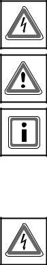
Full wave switch mode (TAKT)
Depending on the prescribed set point, the mains voltage is periodically switched. In this operating mode, almost no harmonics are created. Whole multiples of the mains periods are switched, avoiding DC components. The full oscillation clock principle is especially suited for loads with thermal inertia. For optimization of the mains load, the optional ASM process may be applied in this operating mode.
Phase-angle principle (VAR, with 1P and 3P)
Depending on the prescribed set point, the sine oscillation of the mains voltage is gated using a larger or smaller control angle a. This operating mode is characterized by high control dynamics. In case of phase-angle control, it is possible to compensate harmonics of the mains voltage by using circuit variants (for instance vector group transformer).
Soft-Start-Soft-Down (SSSD)
The operation of large individual loads using the operating mode TAKT may lead to voltage variations on the mains side. The operating mode SSSD greatly reduces the pulse-shaped mains load.
MOSI operation for 1P and 3P
MOSI is a sub-operating mode of the operating modes TAKT and VAR for sensitive heating materials with a high Rhot/Rcold ratio, for instance molybdenum disilicide. The Power Controller always starts with phase-angle maximum value and actual value to avoid high current amplitudes during the heating-up phase and then automatically switches to the set operating mode.

16
Mains load optimization (ASM procedure)
For systems in which several Power Controllers are employed in full wave switch mode TAKT, it is possible that individual Power Controllers are synchronized so that a regular mains load is achieved by defined switching of the individual Power Controller in sequence. This avoids load peaks by random simultaneous switching of many Power Controllers and load troughs are filled up. The upstream transformer and/or the upstream feed point may be designed for a lower load. Besides savings in investment and operating cost, lower mains reactions also result.
2.2 SET POINT CONTROL CHARACTERISTIC
The set point control characteristic of Thyro-P may be easily adapted for the control output signal of the upstream process controller or automation system. All signals customary on the market may be used. The adaption is made by changing the starting and ending points of the control characteristic. Inverted operation (ending value is smaller than the starting value in voltage or current) is also possible.
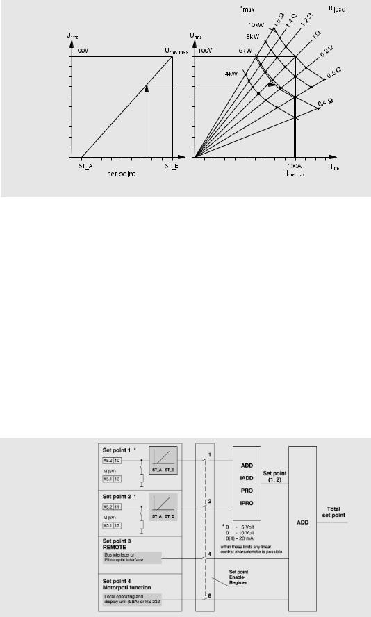
The effective set point is the total set point. It is formed by adding the four set points as shown in fig. 2.
In the simplest case all the set point values are added algebraically. The prerequisite for a set point to influence the total set point value is that it must be enabled by the set point Enable Register.
•Set point 1 (X5.2.10 - X5.1.13 ground) 0-20mA default
•Set point 2 (X5.2.11 - X5.1.13 ground) 0-5V default
The inputs set point 1, 2 are two electrically equal analogue inputs for current or voltage signals, with subsequent A/D converter (resolution 0.025% of the final value), and they may be set to the following signal ranges:
0(4)-20 mA |
(Ri about 250 ) |
max. 24mA |
siehe ”ATTENTION“ |
|
0-5 |
V |
(Ri about 8,8k ) |
max. 12V |
|
0-10 |
V |
(Ri about 5k ) |
max. 12V |
|
The following table shall be used for the hardware configuration of the set point inputs (see also FILE COMPONENT MOUNTING DIAGRAM CONTROL DEVICE, figure 10). If the hardware configuration is changed, the Thyro-P parameters must be changed accordingly with the LBA or the Thyro-Tool.
X221 for Set point input 1
Bridge X221 |
Signal range |
Set point input 1 |
closed* |
0(4) -20mA |
(X5.2.10) |
open |
0-5V / 0-10V |
(X5.2.10) |
X222 for Set point input 2 |
|
|
Bridge X222 |
Signal range |
Set point input 2 |
closded |
0(4)-20mA |
(X5.2.11) |
open* |
0-5V / 0-10V |
(X5.2.11) |
* default
ATTENTION
If the open-circuit voltage of the connected set point exceeds 12V in the 20mA signal range, the set point inputs can be destroyed, if the belonging bridge (X221, X222) is open.
Within the stated input ranges, these values with the control characteristic may be adjusted to any common signal characteristic.
17
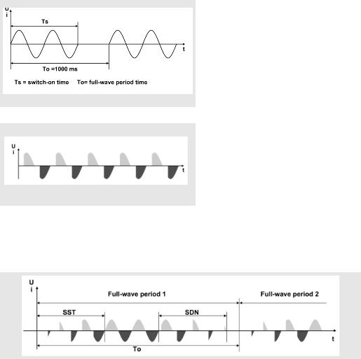
FIG. 1 CONTROL CHARACTERISTIC FOR U CONTROL
For a set point poti (e.g. 5-10 K ) 5V supply voltage can be taken from terminal X5.2.5 (Ri = 220 , short-circuit-proof).
SET POINT CONTROL CHARACTERISTICS
The set point control characteristic (Fig. 1) of Thyro-P may be easily adapted for the control output signal of the upstream process controller or automation system. All signals customary on the market may be used.
The adaption is made by changing the starting and ending points of the control characteristic. Inverted operation (ending value is smaller than the starting value in voltage or current) is also possible.
• Set point 3:
Set point of the superordinate system or PC via fibre optic connection (standard) X30, X31 or via the optional bus interface.
• Set point 4:
Set point input (motor potentiometer function) via LBA or RS 232 from the superordinate system or PC. Set point 4 is stored in case of mains failure.
EFFECTIVE TOTAL SET POINT VALUE
The algebraic addition of the results of set point (1,2) to set point 3 and 4 gives the (effective) total set point value for the set point control characteristic as shown in the following figure.
FIG. 2
TOTAL SET POINT
18
The prerequisite for a set point to influence the total set point value is that it must be enabled by the set point Enable Register. Set point 1 and 2 can be linked using the following functions. The result of this link is called set point (1,2).
Set point link
ADD Set point (1,2) = Set point 1 + Set point 2
IADD Set point (1,2) = Set point 1 - Set point 2
_Pro Set point (1,2) = Set point 1 * Set point 2 [%] 100%
_IPro Set point (1,2) = Set point 1 * (1 - Set point 2 [%] ) 100%
VALUE RANGE OF SET POINT (1,2)
For the link result of set point (1,2) the following value range applies: 0 Set point (1,2) Set point max (Umax, Imax, Pmax).
SET POINT ENABLE REGISTER
The set point Enable Register (AD_P_SW_ENABLE, adr. 94) enables the 4 set points to be shut off or enabled independently. Only enabled set point inputs are part of the effective total set point value.
The shut off or inactive set points are shown by the LBA and can thus, if necessary, be checked before connecting.
The set point Enable Register can be changed from all service units (Bus, Thyro-Tool Familiy, LBA). Example:
8 |
4 |
2 |
1 |
VALUE |
ABBR. |
EXPLANATION |
1 |
1 |
1 |
1 |
15 |
STD |
Standard (all ON) |
1 |
0 |
0 |
0 |
8 |
LOC |
Motor poti-set point 4 (LOCAL) |
0 |
1 |
0 |
0 |
4 |
REMOTE |
Bus set point 3 |
0 |
0 |
1 |
1 |
3 |
ANA |
Analog-set points 1,2 |
0 |
0 |
0 |
0 |
0 |
|
All set points inactive |
2.3 CONTROL TYPES
Thyro-P has five control types effective as underlying controls. Mains voltage variations and load changes are directly and therefore quickly adjusted by bypassing of the slow temperature control system.
Before commissioning of the Power Controller and selection of a control type, you should be familiar with the operating procedure respectively the effect for application.
2.3.1 CONTROLLED VALUE
The controlled value effective on the load is proportionate to the total set point, depending on the control type:
CONTROL TYPE |
CONTROL VALUE (PROPORTIONATE TO THE TOTAL SET POINT) |
P control |
output (active) power, P |
U control |
output voltage, Urms |
U2 control |
output voltage, U2 |
|
rms |
I control |
output current, Irms |
I2 control |
output current, I2 |
|
rms |
LIMITING OF SIGNALS
Independent of the control type set, additionally minimum and maximum limiting values may be set. For this purpose, also refer to Fig. 1 control characteristic.
The maximum limiting values determine the maximum modulation of the load.

19
The minimum limiting values should ensure minimum modulation via the control angle (for instance minimum heating of the load).
CONTROLLER RESPONSE
If the load resistance changes, for instance due to temperature effect, ageing or load fault, then the values effective on the load change as follows:
UNDERLYING |
|
|
LOAD RESISTANCE |
|
LOAD RESISTANCE |
|
EFFECTIVE* |
|
||||||
|
|
|
|
DECREASES |
|
INCREASES |
|
LIMITATIONS |
||||||
CONTROL |
LIMIT |
P |
ULOAD |
ILOAD |
P |
ULOAD |
ILOAD |
|
|
|
|
|
||
U |
Urms max |
larger |
= |
larger |
smaller |
= |
smaller |
Irms max |
Pmax |
|||||
U2 (UxU) |
U |
rms max |
larger |
= |
larger |
smaller |
= |
smaller |
I |
rms max |
P |
max |
||
|
|
|
|
|
|
|
|
|
|
|
||||
|
|
|
|
|
|
|
|
|
|
|||||
I |
Irms max |
smaller |
smaller |
= |
larger |
larger |
= |
Urms max |
Pmax |
|||||
I2 (IxI) |
I |
rms max |
smaller |
smaller |
= |
larger |
larger |
= |
U |
rms max |
P |
max |
||
|
|
|
|
|
|
|
|
|
|
|
||||
|
|
|
|
|
|
|
|
|
|
|||||
P |
Pmax |
= |
smaller |
larger |
= |
larger |
smaller |
Urms max |
Irms max |
|||||
without control |
|
larger |
= |
larger |
smaller |
= |
smaller |
Urms max |
Irms max |
|||||
|
|
|
|
|
|
|
|
|
|
Pmax |
|
|
||
*If one of the limits is exceeded, then the signaling relay K2 and the LED „limit“ react (default values of parameter settings).
General modulation limit |
Ts=Ts max |
|
= max |
|
|
TAB. 1 |
BEHAVIOUR IN CASE OF LOAD CHANGE |
2.4 INDICATIONS
2.4.1 LED INDICATIONS
The LEDs on the front side signal the following states:
• ON |
green: operating indication, power supply controller board |
|
red: RESET active |
• CONTROL |
modulation percentage indication, flashing* |
• LIMIT |
limitation is active, relay K2 switches* |
• PULSE LOCK |
Controller Lock active, but load control is continued at pulse limits |
|
(default value = 0)* |
• FAULT |
fault present* |
• OVERHEAT |
overheating of power section |
|
(in case of ..HF types, check ventilator)* |
|
* Default setting |
Activation of the integrated semiconductor fuse may be signalled using the fault indicating relay K1 rest current, contactor, otherwise separate supply of the control device required). In case of Power Controllers from model current 495A, additional signalling is performed via an indicator at the semiconductor fuse.
2.4.2 RELAY INDICATIONS K1-K2-K3
The Thyro-P Power Controller is fitted with three relays. Each of these relays has a change over contact in principle be allocated a value in the event register. The following table shows the contactor allocation of the relays at the corresponding terminal strips. Presets of parameters by the works (default values) may be found in chapter 3.4.
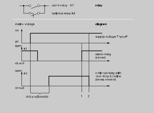
20
ALARM RELAY K1
The relay K1 is activated if a fault is detected in the system. The effective direction, whether it should close or open in case of fault, may be set using the parameter K1 closed-circuit OFF, ON by using LBA or Thyro-Tool Familiy. Which indications lead to switching of the relay may also be set. Recommendation: keep the default setting.
LIMITING RELAY K2
The relay K2 only closes (in default setting) if at least one of the following values is exceeded:
•1. max. admissible effective value of the load current
•2. max. admissible effective value of the load voltage
•3. max. admissible active power of the load
The relay releases if none of the values is exceeded anymore. It is possible to set which indications lead to switching of the relay. Recommendation: keep the default setting.
OPTIONAL RELAY K3
If changes are made to the default relay settings due to the application, then preferrably the relay K3 should be reparameterized.
It is possible to realize functions like for instance a follow-up relay for ventilator control or by pass the alarm relay at startup of the system. It may also be used as a further alarm relay or limiting relay, by reparameterization.
The illustration shows the relay K3 for bridging the startup alarm.
FIG. 3 SWITCH-ON FAULT BRIDGING
2.5 MONITORING
Faults occurring in the Power Controller or in the load circuit are signalled. Signalling is performed via LED (FAULT) and via relay with potential-free change-over contact. The fault buffer may be read via LBA or the interface after selecting the status line. Simultaneously with the fault signal, the pulse shutdown may optionally also be set (Imp.-Absch. OFF, ON). Faults having occurred are shown in the display of LBA by text status indications in the status line. After selecting the status line, the indication may be called up.
21
2.5.1 LOAD MONITORING
MONITORING OF THE LOAD AND MAINS VOLTAGE
Each power section is fitted with its own transformer for creating the synchronization voltages. This also allows monitoring of the phase voltages. In the LBA menu monitoring, the limits may be set for ULine min and ULine max. If larger deviations are detected, then a fault indication is generated.
ABSOLUTE OR RELATIVE MONITORING
Relative monitoring for heating elements for Rhot/Rcold ≈ 1 and absolute monitoring for heating elements with Rhot/Rcold ≠ 1 are possible.
ABSOLUTE VALUE MONITORING CURRENT
This function allows monitoring of a freely selectable absolute current limit. The parameters for the value may be set in ampere.
i |
I < threshold |
TL |
indication 16,17 (Chap. 3.4) |
tV |
FIG. 4 ABSOLUTE VALUE MONITORING
This absolute value monitoring lends itself to one or more load resistances organized in parallel or in series. Generally, the effective current value measured is continuously compared with a presettable absolute current limit for undercurrent or overcurrent. If these limits are undercut or exceeded an indication shows. In case of resistor elements organized in parallel, it is therefore possible, using the lower current limit, to select a partial load interruption. Using the upper current limit, in case of resistors switched in series, short-circuiting of an element may be detected.
RELATIVE MONITORING
This monitoring is sensible if the resistance value of the load slowly changes. Changes in resistance may for instance be caused by temperature changes or by ageing. The current (b) of the Power Controller is regarded as 100% load current (current in fault-free state) after activation of the RESET or CONTROLLER LOCK. The RESET is automatically activated after each startup, restart or after mains outage. In case of relatively slow changes of the current, due to characteristics of the above mentioned heating elements, automatic adjustment of the internal reference value to 100% is performed (b‘).
FIG. 5 RELATIVE MONITORING
22
Quick current changes, which may for instance occur in case of partial.
Quick current changes, which may for instance occur in case of partial short-circuit, may be detected by overcurrent monitoring (max., a – a‘).
Quick current changes, which may for instance occur in case of load breakdown may be detected by undercurrent monitoring (min., c – c‘).
NOTE FOR LOAD MONITORING:
Changes of the burden resistor and parameters can be necessary in case of small load currents or small current flow angles (i. e. small phase angles).
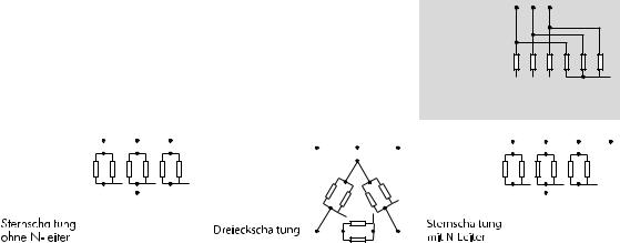
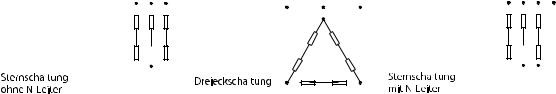
If a Thyro-P 3P is used in phase-angle operating mode, the star point of the load and the star point of the (built-in) voltage transformers should be connected together to ensure an accurate load monitoring. Please contact us in case of need..
The values in the following table apply to ohmic loads. Different values apply may be required for specific heating resistors, for instance IR radiators. The adjustable % values shown in the tables are load current variations on
the present operating values.  Star connection
with separate star points
|
|
|
|
|
|
|
|
|
|
|
|
|
|
|
|
|
|
|
|
|
|
|
|
|
|
|
|
|
|
|
|
|
|
|
|
|
|
|
|
|
|
|
|
|
|
|
|
|
|
|
|
|
|
|
|
|
|
|
|
|
|
|
|
|
|
|
|
|
|
|
|
|
|
|
|
|
|
|
|
|
|
|
|
|
|
|
|
|
|
|
|
|
|
|
|
|
|
|
|
|
|
|
|
|
|
|
|
|
|
|
|
|
|
|
|
|
|
|
|
|
|
|
|
|
|
|
|
|
|
|
|
|
|
|
|
|
|
|
|
|
|
|
|
|
|
|
|
|
|
|
|
|
|
|
|
|
|
|
|
|
|
|
|
|
|
|
|
|
|
|
|
|
|
|
|
|
|
|
|
|
|
|
|
|
|
|
|
|
|
|
|
|
|
|
|
|
|
|
|
|
|
|
|
|
|
|
|
|
|
|
|
|
|
|
|
|
|
|
|
|
|
|
|
|
|
|
|
|
|
|
|
|
|
|
|
|
|
|
|
|
|
|
|
|
|
|
|
|
|
|
|
|
|
|
|
|
|
|
|
|
|
|
|
|
|
|
|
|
|
|
|
|
|
|
|
|
|
|
|
|
|
|
|
|
|
|
|
|
|
|
|
|
|
|
|
|
|
|
|
|
|
|
|
|
|
|
|
|
|
|
|
|
|
|
|
|
|
|
|
|
|
|
|
|
|
|
|
|
|
Star connection |
|
|
|
|
|
|
|
|
|
|
|
|
|
|
Delta connection |
|
|
|
|
|
|
|
|
Star connection |
|
||||||||||||||||||||
|
|
|
|
|
|
|
|
|
|
|
|
|
|
|
|
|
|
|
|
|
|
|||||||||||||||||||||||||
|
without neutral conductor |
|
|
|
|
|
|
|
|
|
|
|
with neutral conductor |
|
||||||||||||||||||||||||||||||||
|
|
|
|
|
|
|
|
|
|
|||||||||||||||||||||||||||||||||||||
HEATING |
1P |
|
|
2P*/3P |
|
|
|
|
|
|
|
|
|
|
3P |
|||||||||||||||||||||||||||||||
ELEMENTS |
|
|
|
|
|
|
|
|
|
|
|
|
|
|
|
|
|
|
|
|
|
|
|
|
|
|
|
|
|
|
|
|
|
|
|
|
|
|
|
|
|
|
|
|
|
|
IN PARALLEL |
|
|
|
|
|
STAR CONNECTION |
STAR CONNECTION |
DELTA |
STAR CONNEC- |
|||||||||||||||||||||||||||||||||||||
FOR EACH |
|
|
|
|
|
WITH SEPARATE |
WITHOUT CONNEC- |
CONNECTION |
TION WITH |
|||||||||||||||||||||||||||||||||||||
STRAND |
|
|
|
|
|
STARPOINTS |
TED NEUTRAL |
|
|
|
|
CONNECTED |
||||||||||||||||||||||||||||||||||
|
|
|
|
|
|
|
|
|
|
|
|
|
|
|
|
|
|
|
|
CONDUCTOR |
|
|
|
|
NEUTRAL CONDUCTOR |
|||||||||||||||||||||
5 |
|
10% |
10% |
|
|
|
|
|
|
|
|
– |
– |
10% |
|
|
|
|
|
|
|
|
|
|
|
|
|
|
||||||||||||||||||
4 |
|
13% |
13% |
|
|
|
|
|
|
|
|
10% |
|
|
|
|
|
– |
13% |
|
|
|
|
|
|
|
|
|
|
|
|
|
|
|||||||||||||
3 |
|
17% |
17% |
|
|
|
|
|
|
|
|
13% |
|
|
|
|
|
10% |
|
|
17% |
|
|
|
|
|
|
|
|
|
|
|
|
|
|
|||||||||||
2 |
|
25% |
25% |
|
|
|
|
|
|
|
|
20% |
|
|
|
|
|
12% |
|
|
25% |
|
|
|
|
|
|
|
|
|
|
|
|
|
|
|||||||||||
1 |
|
50% |
50% |
|
|
|
|
|
|
|
|
50% |
|
|
|
|
|
21% |
|
|
50% |
|
|
|
|
|
|
|
|
|
|
|
|
|
|
|||||||||||
* for Thyro-P 2P: additional external converters in phase L2 are possible.
TAB. 2 PARTIAL LOAD BREAKDOWN WITH HEATING ELEMENTS SWITCHED IN PARALLEL,
UNDERCURRENT, RELATIVE MONITORING
23
|
|
|
|
|
|
|
|
|
|
|
|
|
|
|
|
|
|
|
|
|
|
|
|
|
|
|
|
|
|
|
|
|
|
|
|
|
|
|
|
|
|
|
|
|
|
|
|
|
|
|
|
|
|
|
|
|
|
|
|
|
|
|
|
|
|
|
|
|
|
|
|
|
|
|
|
|
|
|
|
|
|
|
|
|
|
|
|
|
|
|
|
|
|
|
|
|
|
|
|
|
|
|
|
|
|
|
|
|
|
|
|
|
|
|
|
|
|
|
|
|
|
|
|
|
|
|
|
|
|
|
|
|
|
|
|
|
|
|
|
|
|
|
|
|
|
|
|
|
|
|
|
|
|
|
|
|
|
|
|
|
|
|
|
|
|
|
|
|
|
|
|
|
|
|
|
|
|
|
|
|
|
|
|
|
|
|
|
|
|
|
|
|
|
|
|
|
|
|
|
|
|
|
|
|
|
|
|
|
|
|
|
|
|
|
|
|
Star connection |
|
|
|
|
|
|
|
Delta connection |
|
|
|
|
|
|
|
|
|
|
Star connection |
|
|||||
|
without neutral conducter |
|
|
|
|
|
|
|
|
|
|
|
|
|
|
|
|
|
with neutral conductor |
|
||||||
|
|
|
|
|
|
|
|
|
|
|
|
|
|
|
|
|
|
|
|
|
|
|
|
|
|
|
HEATING |
1P |
|
|
|
|
|
|
2P |
|
|
|
|
|
|
|
|
|
|
3P |
|||||||
ELEMENTS |
|
|
|
|
|
|
|
|
|
|
|
|
|
|
|
|
|
|
|
|
|
|
|
|
|
|
IN SERIES FOR |
|
STAR CONNECTION |
|
DELTA CONNECTION |
STAR CONNECTION |
|||||||||||||||||||||
EACH STRAND |
|
WITHOUT CONNECTED |
|
|
|
|
|
|
|
|
|
|
WITH CONNECTED |
|||||||||||||
|
|
|
NEUTRAL CONDUCTOR |
|
|
|
|
|
|
|
|
|
|
NEUTRAL CONDUCTOR |
||||||||||||
6 |
|
10% |
– |
|
– |
10% |
|
|
|
|
|
|||||||||||||||
5 |
|
13% |
10% |
|
|
|
|
|
|
– |
13% |
|
|
|
|
|
||||||||||
4 |
|
17% |
10% |
|
|
|
|
|
10% |
|
|
|
|
|
|
|
17% |
|
|
|
|
|
||||
3 |
|
25% |
14% |
|
|
|
|
|
13% |
|
|
|
|
|
|
|
25% |
|
|
|
|
|
||||
2 |
|
50% |
25% |
|
|
|
|
|
26% |
|
|
|
|
|
|
|
50% |
|
|
|
|
|
||||
TAB. 3 PARTIAL SHORT-CIRCUIT WITH HEATING ELEMENTS SWITCHED IN SERIES, OVERCURRENT, RELATIVE MONITORING
AGEING OF LOAD RESISTORS
Thyro-P determines the load conductance separately for each phase. These values are available from LBA, Thyro-Tool Familiy and the Bus interface. The current resistance can be determined by reading out and converting from the conductance.
The following table offers an overview of the possible monitoring functions of the Thyristor Power Controller Thyro-P.
TYPE OF |
|
PARAMETER |
DEFAULT / |
MONITORING |
|
SETTINGS |
REMARKS |
Unet max |
mains overvoltage |
input in volts |
Type voltage + 20% |
Unet min |
mains undervoltage |
input in volts |
Type voltage - 20% |
Iload max-REL |
overcurrent |
0-100% |
REL_ABS = REL |
|
overcurrent relative |
Re: measured load current |
UE_S = ON |
|
|
after each RESET/control lock |
|
|
|
|
|
Iload max-ABS |
overcurrent |
input in ampere |
REL_ABS = ABS |
|
absolute |
|
UE_S = ON |
|
|
|
|
Iload min-REL |
undercurrent |
0 to 99% |
REL_ABS = REL |
|
relative |
Re: measured load current |
UN_S = ON |
|
|
after each RESET/control lock |
|
Iload min-ABS |
undercurrent |
input in ampere |
REL_ABS = ABS |
|
absolute |
|
UN_S = ON |
pulse switch |
pulse switch off |
ON: pulse switch off after |
indication is always |
off by software |
|
fault indication |
issued |
|
|
OFF: in case of fault |
in case of synchronization |
|
|
|
SYT 9, RESET of all Power |
|
|
|
Controllers is required |
K1 |
alarm relay K1 |
ON: relay K1 |
|
open circuit |
|
released in case of fault |
|
|
|
OFF: relay K1 |
the alarm relay switches |
|
|
pulled-in in case of fault |
upon activation of |
|
|
|
RESET |
TAB. 4 |
OVERVIEW MONITORING |
|
|

24
2.5.2 VENTILATOR MONITORING
The separately ventilated Power Controllers (-...HF) are fitted with thermal monitoring. The temperature is measured on the heat sink. In case of a temperature overrange, a fault inducation is issued (Profibus, LED OVERHEAT).
ATTENTION
Activating this monitoring function is obligatory if the Thyro-P is operated under UL conditions.
25
3. MODE OF OPERATION
This chapter shows the operating options of Thyro-P using LBA and Thyro-Tool Familiy.
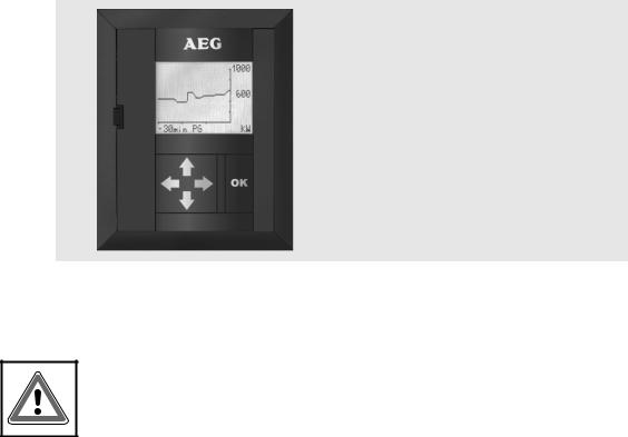
3.1 LOCAL OPERATING AND DISPLAY UNIT (LBA)
The optional LBA (IP30, protection classification 3) has five keys and a backlit graphical LC display for 7 x 19 characters respectively 64 x 114 pixels. In the standard version, the languages German, English and French are available.
FIG. 6 LOCAL OPERATING AND
DISPLAY UNIT (LBA)
The LBA may be connected or disconnected from the RS 232 interface of the Thyro-P control device during operation. After plugging into the interface and automatic loading of the parameters, the LBA displays its main menu.
ATTENTION
Before storing (store in Thyro-P / LBA under Thyro-P) the parameters must always be saved in the EEPROM of the LBA first (store in LBA).
If no key is pressed for one minute the operation display appears. This does not apply if a line diagram is running. If no communication is achieved after plugging in the LBA between LBA and Power Controller in case of fault, then a self-test is performed. Using the LBA, Thyro-P may be parameterized and monitored under menu control. It is possible to display up to three process data values (for instance the actual values of current, voltage or power occurring at the load) in double character height. Further values which may be displayed are the set point value as well as parameter data and fault indications. Furthermore, display of a value in graphical form as line diagram is possible. The time and value axes may be set by parameters and so adjusted to requirements. Using the LBA, the parameters of one Thyro-P may be copied to another Thyro-P. More details on this can be found in the chapter LBA menus.
3.1.1 LBA KEYBOARD FUNCTIONS
The LBA has a total of 5 standard keys: with an activatable parameterizing lock (see table 5). Four arrow keys and one OK key. By moving the cursor mark (>) using the corresponding keys (up arrow, down arrow), the desired function may then be selected using the OK key. An underlined language/ function is in each case selected. An unnamed 6th key is available behind the opening in the front of the LBA, the reset key. If this is operated, then the functions RESET of Thyro-P is performed.

26
FUNCTIONS OF LBA KEYS: |
|
|
KEY |
DISPLAY |
FUNCTION |
|
Cursor before menu text: |
selection of the higher level (back) |
|
|
|
|
Cursor on the figure: |
select prior (higher value) position |
|
Cursor on the figure: |
select next (lower value) position |
|
|
|
|
Cursor before menu text: |
move cursor to the prior line, possible scroll |
|
|
upward (only indented lines may be scrolled) |
|
Cursor on the figure: |
increase value |
|
Cursor on the parameter: |
switch on |
|
Cursor before menu text: |
cursor on subsequent line, possible scroll down- |
|
|
ward |
|
Cursor on the figure: |
reduce value until minimal admissible value is |
|
|
reached |
|
Cursor on the parameter: |
switch off |
OK |
Cursor before menu text: |
selection of a figure or of an input field |
|
Cursor on the figure: |
takeover of the modification into Thyro-P and |
|
|
deselection of the selected field |
|
Cursor on the parameter: |
takeover of the modification into Thyro-P and |
|
|
deselection of the selected field |
|
Operation display: |
deselection of the operation display |
|
Parameter loading process |
Parameterizing process is temporarily |
|
Thyro-P → LBA |
inactivated |
OK OK |
Line diagram: |
deselection of the line diagram display |
No key pressed |
|
operation display is activated; this does |
(for 1 minute) |
|
not apply in case of selected line diagram |
|
Operation display: |
Parameterizing lock is self-activating on release |
TAB. 5 FUNCTIONS OF THE LBA-KEYS
3.1.2 LBA MAIN MENU
The top line always contains the name of the menu or of the submenu. The lowest line, the status line, always contains the configuration of the Power Controller or in case of existing indications, the word status indication.
The main menu (function selection menu) appears on the LBA display after plugging the LBA into Thyro-P. It looks like this:
 Loading...